Embed Size (px)
Citation preview
Copyright© 1995-2007 Underwriters Laboratories Inc. All rights reserved. No portion of this material may be reprintedin any form without the express written permission of Underwriters Laboratories Inc. or as otherwise provided in writing.
PWB Thermal Management and UL Pre-Selection Programs
Presented byCrystal VanderpanUnderwriters Laboratories, Inc.IPC Expo April 2008
p/2
Crystal Vanderpan
• UL’s Principal Engineer for Printed Circuit Technologies
• Joined UL in 1995
• Technical rep on UL STP for PWB and CCL standards
• B.S. Chemical Engineering/Materials Science, UC Davis
• Subcommittee chairman ASTM D09.07 Electrical and Electronic Insulating Materials
• Email: [email protected] or visit www.ul.com
p/3
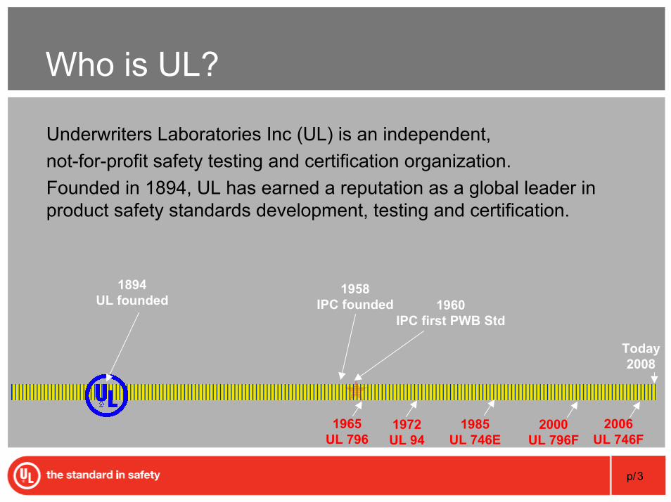
Who is UL?
Underwriters Laboratories Inc (UL) is an independent, not-for-profit safety testing and certification organization.Founded in 1894, UL has earned a reputation as a global leader in product safety standards development, testing and certification.
1894UL founded
Today2008
1965UL 796
1972UL 94
2000UL 796F
2006UL 746F
1958IPC founded 1960
IPC first PWB Std
1985UL 746E
Copyright© 1995-2007 Underwriters Laboratories Inc. All rights reserved. No portion of this material may be reprintedin any form without the express written permission of Underwriters Laboratories Inc. or as otherwise provided in writing.
Background on UL’s Certification Program for
PWBs and Laminates
p/5
Printed Board Terminology
Many terms are used for circuit boards in the electronics industry• Printed Boards (PBs)• Printed Circuit Boards (PCBs)• Printed Wiring Boards (PWBs)
Official IPC term is currently “Printed Boards”
In order to reduce confusion with other components and end products tested within UL, we continue to use the term PWBs which will be used through-out this presentation for PBs.
p/6
Demand Driver – for UL Certification
End Product Safety Issues for PWB• Intended location• Environmental issues – RoHS requirements• Maximum operating temperature• Flammability• Material characteristics • Conductor Adhesion• Delamination
p/7
Pre-selection
The process of assessing and choosing insulating materials for electrical products.
p/8
Advantages of Pre-selection
• Aides in material selection during the design stage
• Compare and evaluate material performance levels
• Eliminate testing each material in specific part configurations
• Faster qualification of alternate materials
• Pre-selection successfully used as a material performance specification in product standards for decades
• Faster time to market
p/9
PWB Property Characterization
PWB Parameters• Solder Limits• Maximum Operating Temperature (MOT)
• Conductor Adhesion (Bond Strength)• Delamination
• Flammability Classification• Direct Support (DSR)• Comparative Tracking Index (CTI)
p/10
PWB Solder Limits
Solder limits represent assembly process• Maximum surface temperature • Cumulative exposure time
Simulated on PWB samples with thermal shock (thermal stress) test.
• Designed to evaluate the physical fatigue of boards exposed to the anticipated assembly soldering temperatures (Solder Limits)
Test with maximum temperature or multiple solder limit• Specified by PWB mfr
p/11
Multiple Solder Limits
Assembly processes now use Surface Mount Technology (SMT)
• Traditional solder float test does not represent industry practices
• PWBs exposed to at least 3 cycles of reflow process• #1 cycle for single sided, #2 cycles for double sided, #3 cycle for rework
• Multiple solder limits are used to represent the temperature profile during the soldering operation
p/12
Maximum Operating Temperature (MOT)
MOT represents PWB maximum continuous use temperature• End product exposure under normal operating conditions• Minimum acceptable MOT specified by end product requirements• Can not exceed dielectric material mechanical or electrical RTI
Simulated on PWBs with short term thermal conditioning• Exposure temperature based on PWB mfr request • MOT determined by analysis of PWB physical properties
• Conductor adhesion and board delamination
p/13
Relative Thermal Index (RTI)
A temperature assigned to the dielectric material • Does not unacceptably degrade the material• Electrical and Mechanical properties
• Electrical – Dielectric Strength• Mechanical – Flexural Strength and Tensile Strength
Determined by a benchmark comparison of temperature, time, and critical property degradation after long-term thermal aging
p/14
PWB Flammability Classification
Classification represents small scale sample evaluation and burntime• Flame Ratings - V-0, V-1, HB, VTM-0, VTM-1, VTM-2
Determined by performing UL94 burning tests on the board• With and without coatings based on finished board• After thermal shock (thermal stress) exposure
Minimum acceptable flame class is specified by end product requirements
p/15
Direct Support Requirements (DSR)
Direct Support Requirements (DSR) represent performance characteristics for Recognized laminates in direct contact with current carrying parts at 120V or less.
p/16
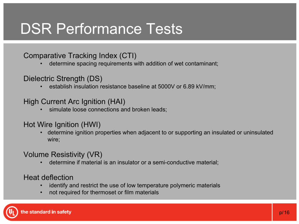
DSR Performance TestsComparative Tracking Index (CTI)
• determine spacing requirements with addition of wet contaminant;
Dielectric Strength (DS)• establish insulation resistance baseline at 5000V or 6.89 kV/mm;
High Current Arc Ignition (HAI)• simulate loose connections and broken leads;
Hot Wire Ignition (HWI)• determine ignition properties when adjacent to or supporting an insulated or uninsulated
wire;
Volume Resistivity (VR)• determine if material is an insulator or a semi-conductive material;
Heat deflection• identify and restrict the use of low temperature polymeric materials• not required for thermoset or film materials
Copyright© 1995-2007 Underwriters Laboratories Inc. All rights reserved. No portion of this material may be reprintedin any form without the express written permission of Underwriters Laboratories Inc. or as otherwise provided in writing.
How lead-free affects thermal management of the PWB
p/18
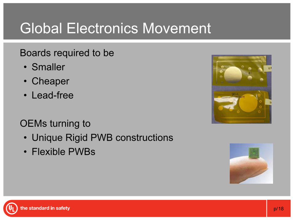
Global Electronics MovementBoards required to be • Smaller• Cheaper• Lead-free
OEMs turning to• Unique Rigid PWB constructions• Flexible PWBs
p/19
Communication is Key
Communication needed up/down the supply chain
Switching to lead-free involves the OEM, EMS, Assembler and PWB Fabricator,• determine if lead-free is appropriate direction
for end product
p/20
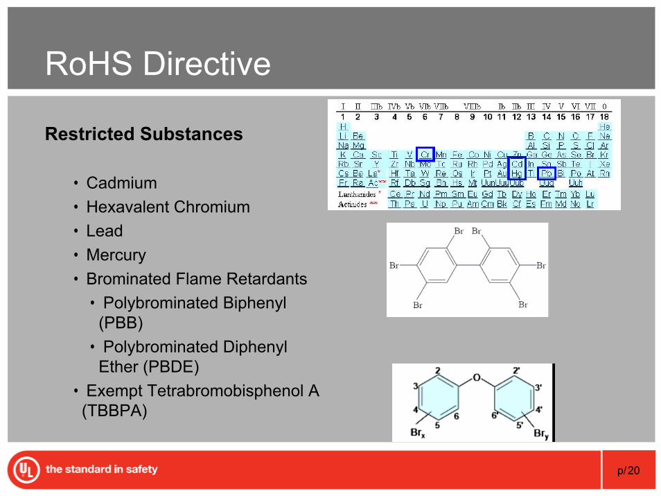
RoHS Directive
Restricted Substances
• Cadmium• Hexavalent Chromium• Lead • Mercury • Brominated Flame Retardants
• Polybrominated Biphenyl (PBB)
• Polybrominated DiphenylEther (PBDE)
• Exempt Tetrabromobisphenol A (TBBPA)
p/21
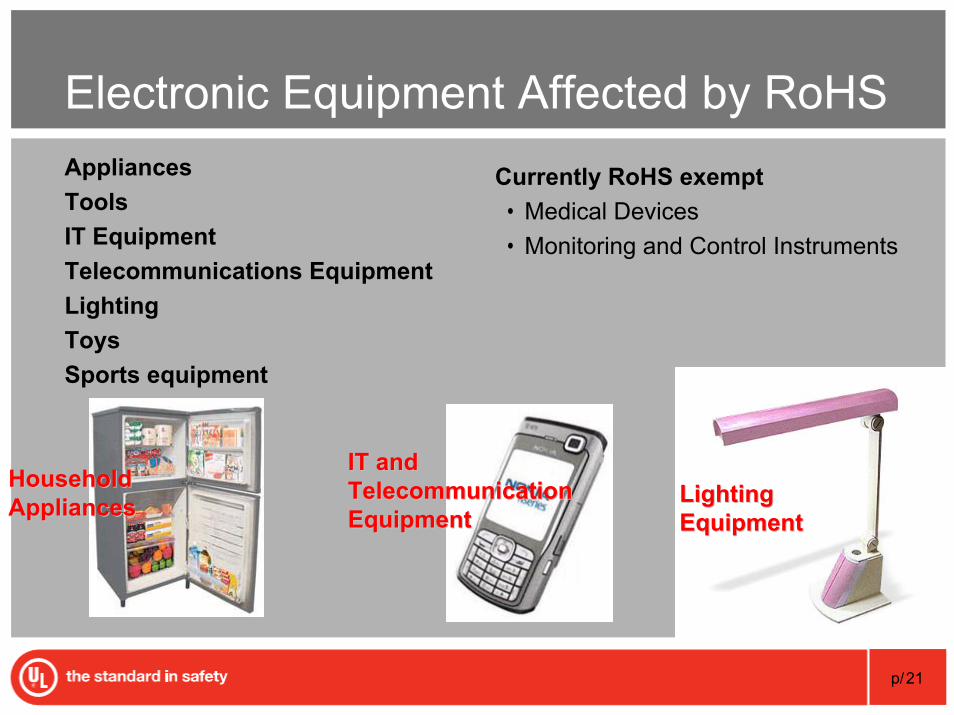
Electronic Equipment Affected by RoHSAppliancesToolsIT EquipmentTelecommunications EquipmentLightingToysSports equipment
Currently RoHS exempt• Medical Devices• Monitoring and Control Instruments
Lighting Lighting EquipmentEquipment
Household Household AppliancesAppliances
IT and IT and Telecommunication Telecommunication EquipmentEquipment
p/22
Lead-free Processing Challenge
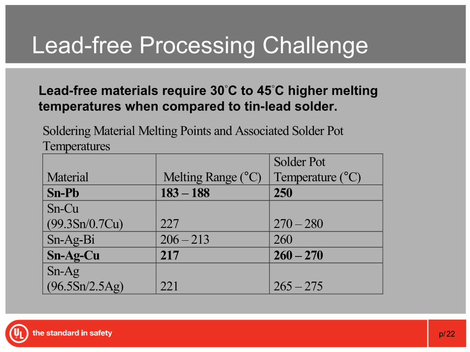
Lead-free materials require 30°C to 45°C higher melting temperatures when compared to tin-lead solder.
Soldering Material Melting Points and Associated Solder Pot Temperatures
Material Melting Range (°C) Solder Pot Temperature (°C)
Sn-Pb 183 – 188 250 Sn-Cu (99.3Sn/0.7Cu) 227 270 – 280 Sn-Ag-Bi 206 – 213 260 Sn-Ag-Cu 217 260 – 270 Sn-Ag (96.5Sn/2.5Ag) 221 265 – 275
p/23
Lead-free Processing Challenge
Lead-free temperatures reduce the process tolerance• Tin/Lead reflow 225°C• Lead-free reflow 245°C+• Component max temp 260°C
Tolerance reduced by more than 50%• 15°C for lead-free instead of 35°C for tin/lead
Affects both PWB mfrs and Assemblers
p/24
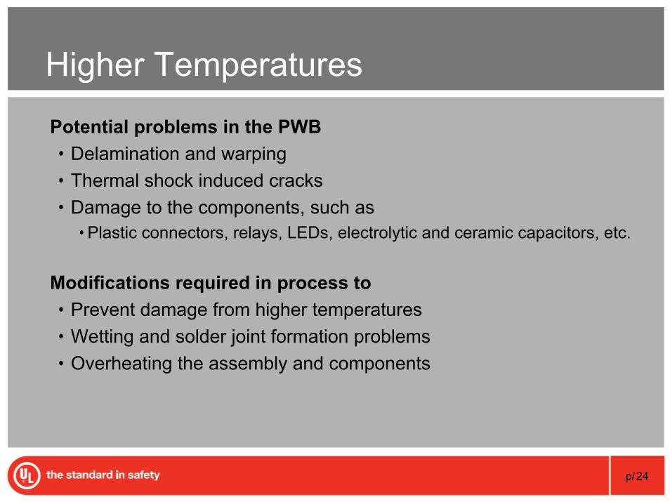
Higher Temperatures
Potential problems in the PWB• Delamination and warping• Thermal shock induced cracks• Damage to the components, such as
• Plastic connectors, relays, LEDs, electrolytic and ceramic capacitors, etc.
Modifications required in process to • Prevent damage from higher temperatures • Wetting and solder joint formation problems• Overheating the assembly and components
p/25
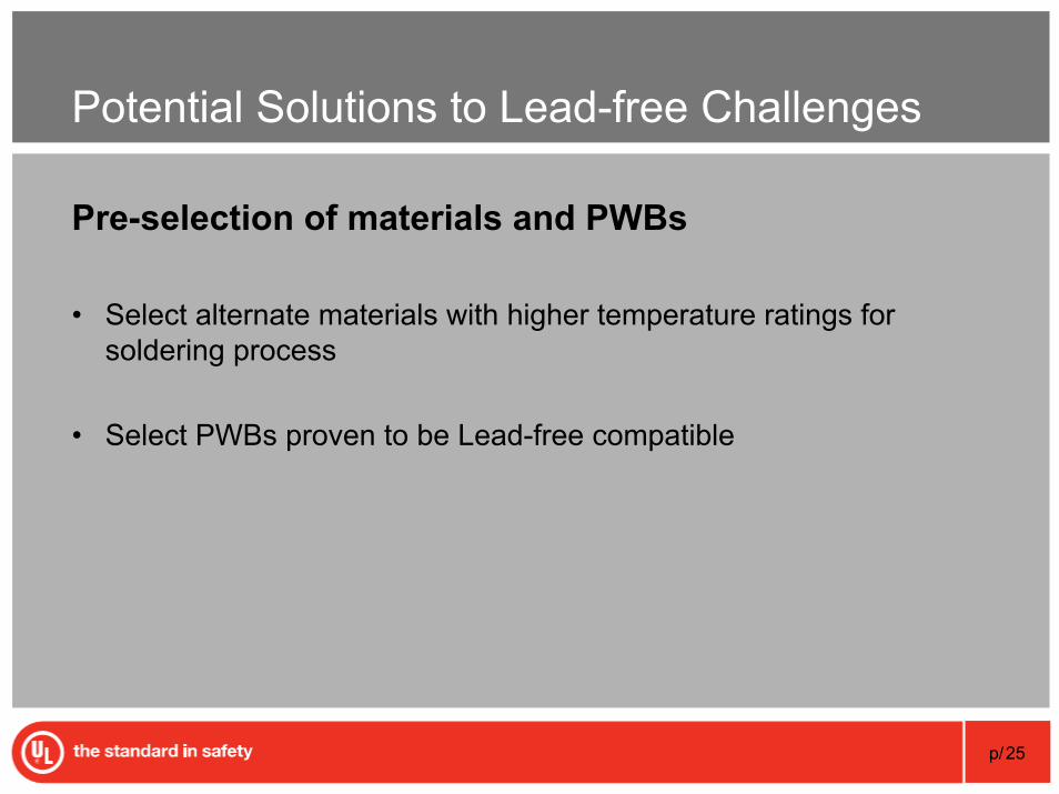
Potential Solutions to Lead-free Challenges
Pre-selection of materials and PWBs
• Select alternate materials with higher temperature ratings for soldering process
• Select PWBs proven to be Lead-free compatible
Copyright© 1995-2007 Underwriters Laboratories Inc. All rights reserved. No portion of this material may be reprintedin any form without the express written permission of Underwriters Laboratories Inc. or as otherwise provided in writing.
How to Reduce Time to Market When Selecting Alternate Materials
p/27
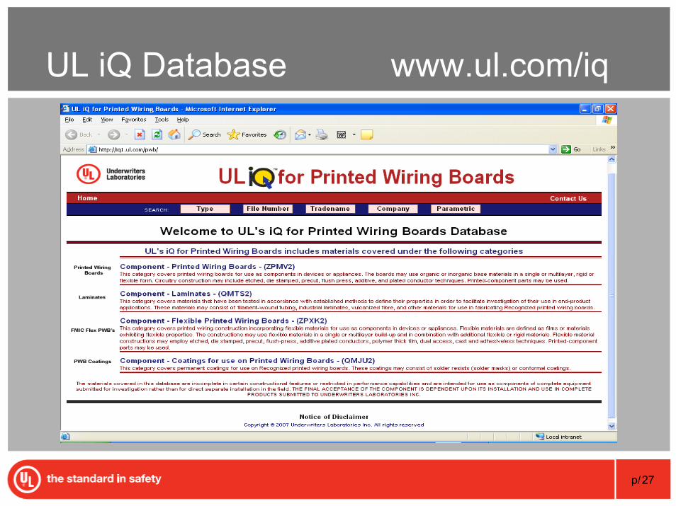
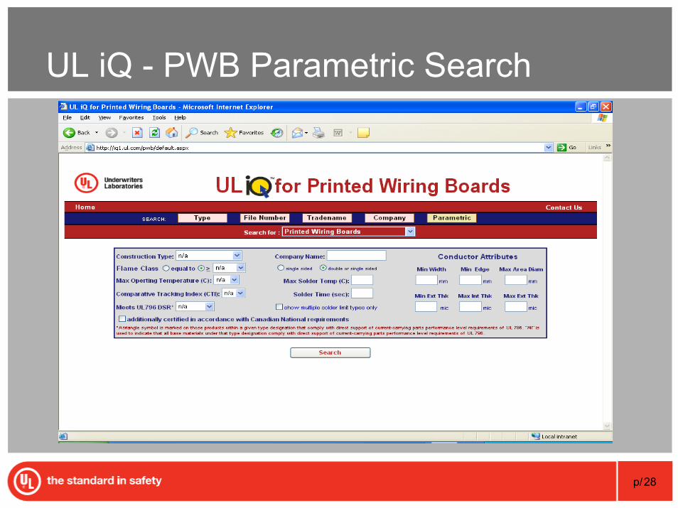
UL iQ Database www.ul.com/iq
p/28
UL iQ - PWB Parametric Search
p/29
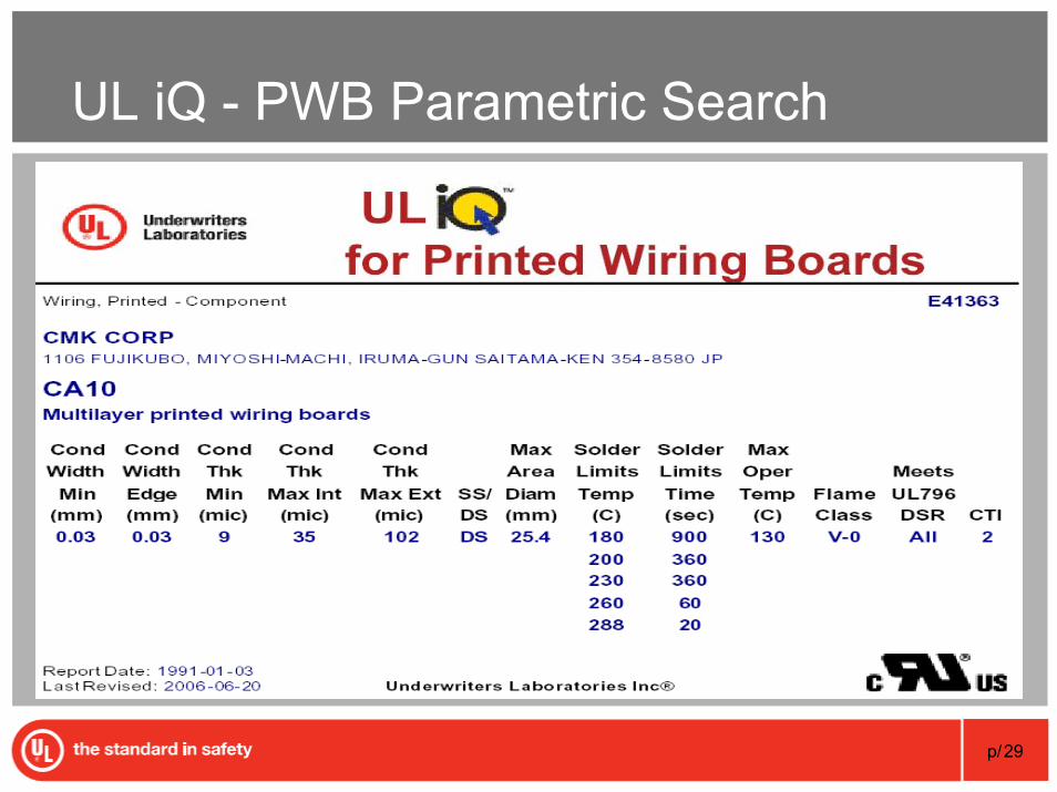
UL iQ - PWB Parametric Search
p/30
PWB Material Pre-selection Programs
Two pre-selection programs for materials• Metal Clad Industrial Laminate (MCIL or CCIL)• Permanent Coatings Program
Allow generically similar materials to be characterized as suitable for cross substitution without re-evaluation in the PWB.
p/31
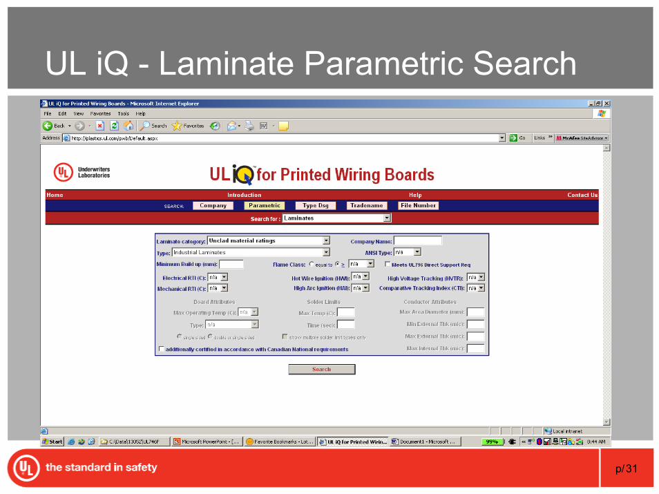
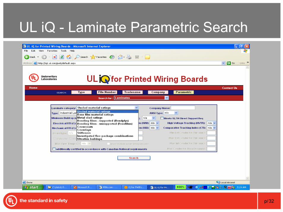
UL iQ - Laminate Parametric Search
p/32
UL iQ - Laminate Parametric Search
p/33
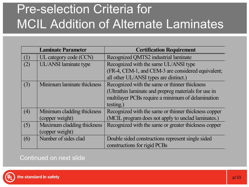
Pre-selection Criteria for MCIL Addition of Alternate Laminates
Laminate Parameter Certification Requirement (1) UL category code (CCN) Recognized QMTS2 industrial laminate (2) UL/ANSI laminate type Recognized with the same UL/ANSI type
(FR-4, CEM-1, and CEM-3 are considered equivalent; all other UL/ANSI types are distinct.)
(3) Minimum laminate thickness Recognized with the same or thinner thickness (Ultrathin laminate and prepreg materials for use in multilayer PCBs require a minimum of delamination testing.)
(4) Minimum cladding thickness (copper weight)
Recognized with the same or thinner thickness copper (MCIL program does not apply to unclad laminates.)
(5) Maximum cladding thickness (copper weight)
Recognized with the same or greater thickness copper
(6) Number of sides clad Double sided constructions represent single sided constructions for rigid PCBs
Continued on next slide
p/34
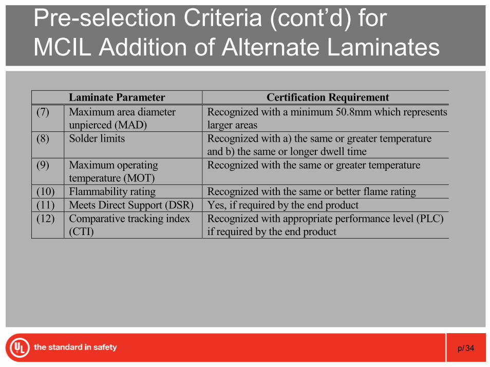
Pre-selection Criteria (cont’d) for MCIL Addition of Alternate Laminates
Laminate Parameter Certification Requirement (7) Maximum area diameter
unpierced (MAD) Recognized with a minimum 50.8mm which represents larger areas
(8) Solder limits Recognized with a) the same or greater temperature and b) the same or longer dwell time
(9) Maximum operating temperature (MOT)
Recognized with the same or greater temperature
(10) Flammability rating Recognized with the same or better flame rating (11) Meets Direct Support (DSR) Yes, if required by the end product (12) Comparative tracking index
(CTI) Recognized with appropriate performance level (PLC) if required by the end product
p/35
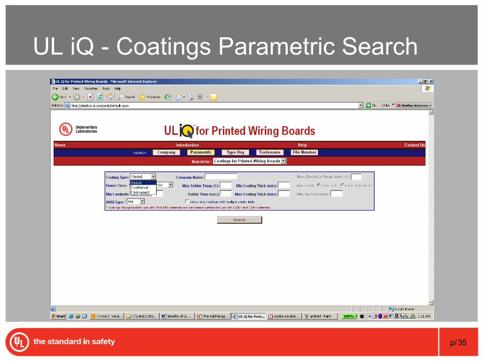
UL iQ - Coatings Parametric Search
p/36
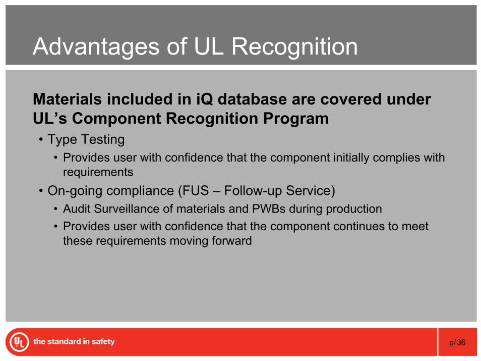
Advantages of UL Recognition
Materials included in iQ database are covered under UL’s Component Recognition Program• Type Testing
• Provides user with confidence that the component initially complies with requirements
• On-going compliance (FUS – Follow-up Service)• Audit Surveillance of materials and PWBs during production• Provides user with confidence that the component continues to meet
these requirements moving forward
p/37
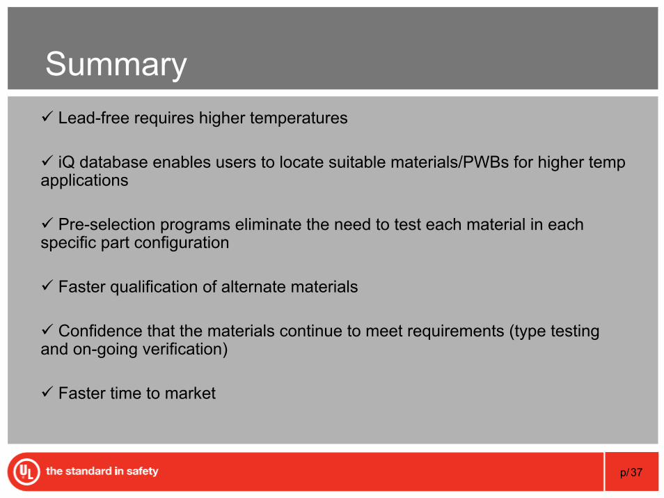
SummaryLead-free requires higher temperatures
iQ database enables users to locate suitable materials/PWBs for higher temp applications
Pre-selection programs eliminate the need to test each material in each specific part configuration
Faster qualification of alternate materials
Confidence that the materials continue to meet requirements (type testing and on-going verification)
Faster time to market
Copyright© 1995-2007 Underwriters Laboratories Inc. All rights reserved. No portion of this material may be reprintedin any form without the express written permission of Underwriters Laboratories Inc. or as otherwise provided in writing.
Thank You
Questions?


![Melinda Pavey Preselection [No Video]](https://img.pdfslide.us/doc/110x75/55cf985e550346d033973c2f/melinda-pavey-preselection-no-video.jpg)