Embed Size (px)
Citation preview
Copyright ©2008 Underwriters Laboratories Inc.® 7/08
UL Listing Document Guide
1. Installation Wiring Documents 2. Operation 3. Functionality 4. Programming Options 5. Testing/Maintenance 6. Compatibilities 7. System Configurations 8. System Power/Size 9. Operating Instructions
Copyright ©2008 Underwriters Laboratories Inc.® 7/08 2
1. INSTALLATION WIRING DIAGRAMS
INSTRUCTIONS FOR USE The information for wiring and installation can be presented in different formats; a single wiring drawing can be used for everything, separate wiring diagrams for each circuit type, or any combination. For all of these approaches, all terminals including all terminal numbers, and types of circuits identified including the information required in the individual circuit lists should be identified.
Main Supply Circuit
An installation wiring diagram that shows the installation terminals or leads to which field connections are to be made as they would appear during an installation. The terminal numbers on the unit should agree with the numbers on the drawing.
A statement that the circuit is supervised Nominal Voltage, Frequency Maximum current or specific power supply intended to be used A terminal for the connection of a grounded conductor shall be properly
identified
Rechargeable Battery Circuit An installation wiring diagram that shows the installation terminals or leads to
which field connections are to be made as they would appear during an installation. The terminal numbers on the unit should agree with the numbers on the drawing.
A statement that the circuit is supervised Voltage Max. current, amp-hour capacity Type of suitable battery Expected standby operating time(s) The maximum time during which the standby operating source maintains the
minimum operating voltage (85 percent of rated voltage). This is required for releasing devices under continuous load that can’t maintain 85 percent of the rated operating voltage to the releasing devices for 60 seconds after energizing.
Indication that a mechanical manual release is to be employed. This is required for systems that; a) are intended for Halon 1301 release as described in NFPA 12A and/or clean agents described in NFPA 2001, b) that employ batteries as its standby operating power source, and c) are provided with a manual release switch and for which no audible and visual annunciation of a trouble signal is provided when the standby source is solely powering the product and is depleted to 85 percent of its nominal marked voltage.
Copyright ©2008 Underwriters Laboratories Inc.® 7/08
Initiating Device Circuit (IDC) An installation wiring diagram that shows the installation terminals or leads to
which field connections are to be made as they would appear during an installation. The terminal numbers on the unit should agree with the numbers on the drawing.
If circuit is power limited, needs to be marked “Power-Limited Circuit”. A statement that the circuit is supervised Type of device (automatic, manual, waterflow, sprinkler supervisory,
watchman supervisory, etc.) Initiating devices having integral trouble contacts shall be shown connected
to the initiating device circuit such that transfer of the contacts do not impair alarm signaling from any other initiating circuit. This is not needed for initiating devices signaling a trouble condition caused by electrical disconnection of the device, or by removing the device from it’s plug-in base
Max. line impedance Max. current, rated voltage, and frequency Unfiltered half and full-wave rectified voltages identified Identified by class or by class/style per tables 51.1-51.3 & 51.1.6 Class A & B wiring connections with initiating devices (show in and out wiring) Impedance values for testing at which ground faults are annunciated Maximum rated operating voltage range if intended to be used with two wire
smoke detectors If necessary, EOL resistor by name or trademark of the manufacturer and
model number. This includes directions for installation of EOL resistor (whether EOL resistor is supplied with system or not) and removal of any test resistors not intended to be part of final system assembly
Notification Appliance Circuit (NAC)
An installation wiring diagram that shows the installation terminals or leads to which field connections are to be made as they would appear during an installation. The terminal numbers on the unit should agree with the numbers on the drawing.
A statement that the circuit is supervised If circuit is power limited, needs to be marked “Power-Limited Circuit”. Type of signaling devices and connection, if polarized, indicate proper wiring
with plus or minus (+, -) symbols, or equivalent for proper field connection Max. current, rated voltage, and frequency Max. line impedance or equivalent Each circuit identified with rating designation per table 61.1. If special
application, either identify appliances/devices by mfr’s name and model along with max. number of devices per circuit or reference the device compatibility section/document
Max. RMS operating current for any single NAC appliance, where sync. NAC appliances not employed
Each NAC, identify if synchronized NAC appliance are permitted. If synchronized NAC appliances employed, specify max. # per circuit if # exceeds loading calculations
Unfiltered half and full-wave rectified voltages identified Identified by class or by class/style per tables 51.1-51.3 & 51.1.6 Impedance values for testing at which ground faults are annunciated

Copyright ©2008 Underwriters Laboratories Inc.® 7/08 4
Notification Appliance Circuit (NAC), continued Circuits, using the exception to 51.3.3/51.4.3 for riser conductors installed in
accordance with the survivability from attack by fire requirements in National Fire Alarm Code, NFPA 72, must have specifics covering the installation constraints clearly detailed in the wiring diagram instructions.
If necessary, EOL resistor by name or trademark of the manufacturer and model number. This includes directions for installation of EOL resistor (whether EOL resistor is supplied with system or not) and removal of any test resistors not intended to be part of final system assembly
Supplementary Circuits
An installation wiring diagram that shows the installation terminals or leads to which field connections are to be made as they would appear during an installation. The terminal numbers on the unit should agree with the numbers on the drawing.
A statement whether the circuit is supervised/not supervised If circuit is power limited, needs to be marked “Power-Limited Circuit”. Max. current, voltage, frequency Unfiltered half and full-wave rectified voltages identified Impedance values for testing at which ground faults are annunciated
Signaling Line Circuit (SLC)
An installation wiring diagram that shows the installation terminals or leads to which field connections are to be made as they would appear during an installation. The terminal numbers on the unit should agree with the numbers on the drawing.
A statement that the circuit is supervised If circuit is power limited, needs to be marked “Power-Limited Circuit”. Max. voltage, rated current, and frequency (RS-232 & RS-485 do not require
these) Max. line impedance Either identify the Mfr’s. Name, model designation for appliances to be used
on the circuit or reference the device compatibility section/document Unfiltered half and full-wave rectified voltages identified Identified by class or by class/style per tables 51.1-51.3 & 51.1.6 Impedance values for testing at which ground faults are annunciated Circuits, using the exception to 51.4.3 for riser conductors installed in
accordance with the survivability from attack by fire requirements in National Fire Alarm Code, NFPA 72, must have specifics covering the installation constraints clearly detailed in the wiring diagram instructions.
Remote Annunciator / Keypad Circuits
An installation wiring diagram that shows the installation terminals or leads to which field connections are to be made as they would appear during an installation. The terminal numbers on the unit should agree with the numbers on the drawing.
A statement that the circuit is supervised or not supervised If circuit is power limited, needs to be marked “Power-Limited Circuit”. Max. voltage, rated current, and frequency (RS-232 & RS-485 do not require
these) Max. line impedance
Copyright ©2008 Underwriters Laboratories Inc.® 7/08 5
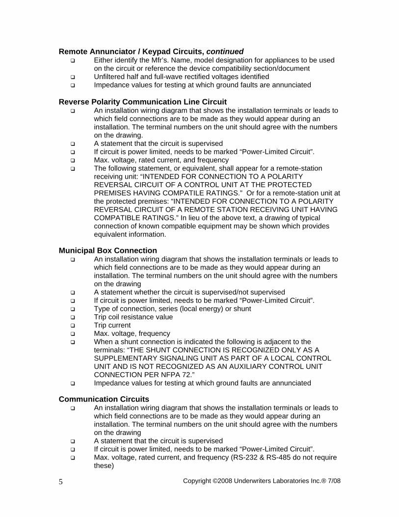
Remote Annunciator / Keypad Circuits, continued Either identify the Mfr’s. Name, model designation for appliances to be used
on the circuit or reference the device compatibility section/document Unfiltered half and full-wave rectified voltages identified Impedance values for testing at which ground faults are annunciated
Reverse Polarity Communication Line Circuit
An installation wiring diagram that shows the installation terminals or leads to which field connections are to be made as they would appear during an installation. The terminal numbers on the unit should agree with the numbers on the drawing.
A statement that the circuit is supervised If circuit is power limited, needs to be marked “Power-Limited Circuit”. Max. voltage, rated current, and frequency The following statement, or equivalent, shall appear for a remote-station
receiving unit: “INTENDED FOR CONNECTION TO A POLARITY REVERSAL CIRCUIT OF A CONTROL UNIT AT THE PROTECTED PREMISES HAVING COMPATILE RATINGS.” Or for a remote-station unit at the protected premises: “INTENDED FOR CONNECTION TO A POLARITY REVERSAL CIRCUIT OF A REMOTE STATION RECEIVING UNIT HAVING COMPATIBLE RATINGS.” In lieu of the above text, a drawing of typical connection of known compatible equipment may be shown which provides equivalent information.
Municipal Box Connection
An installation wiring diagram that shows the installation terminals or leads to which field connections are to be made as they would appear during an installation. The terminal numbers on the unit should agree with the numbers on the drawing
A statement whether the circuit is supervised/not supervised If circuit is power limited, needs to be marked “Power-Limited Circuit”. Type of connection, series (local energy) or shunt Trip coil resistance value Trip current Max. voltage, frequency When a shunt connection is indicated the following is adjacent to the
terminals: “THE SHUNT CONNECTION IS RECOGNIZED ONLY AS A SUPPLEMENTARY SIGNALING UNIT AS PART OF A LOCAL CONTROL UNIT AND IS NOT RECOGNIZED AS AN AUXILIARY CONTROL UNIT CONNECTION PER NFPA 72.”
Impedance values for testing at which ground faults are annunciated Communication Circuits
An installation wiring diagram that shows the installation terminals or leads to which field connections are to be made as they would appear during an installation. The terminal numbers on the unit should agree with the numbers on the drawing
A statement that the circuit is supervised If circuit is power limited, needs to be marked “Power-Limited Circuit”. Max. voltage, rated current, and frequency (RS-232 & RS-485 do not require
these)

Copyright ©2008 Underwriters Laboratories Inc.® 7/08 6
Communication Circuits, continued Max. line impedance or equivalent Type consistent with path capabilities as described in 40.2.1-40.2.7 for active
multiplex, 40.4.1-40.4.7 for two way private radio frequency multiplex, and 40.5.1-40.5.12 for one way private radio frequency systems.
Power Output Circuits
An installation wiring diagram that shows the installation terminals or leads to which field connections are to be made as they would appear during an installation. The terminal numbers on the unit should agree with the numbers on the drawing
A statement whether the circuit is supervised/not supervised If circuit is power limited, needs to be marked “Power-Limited Circuit”. Indicate whether regulated or special applications If regulated, a single voltage and max. load current rating If special applications, either identify the Mfr’s. Name, model designation for
appliances to be used on the circuit or reference the device compatibility section/document
Impedance values for testing at which ground faults are annunciated when ground faults affect operation
See General Wiring for duplicate terminal requirements Power output circuit battery backed up or not
Releasing Device Circuit
An installation wiring diagram that shows the installation terminals or leads to which field connections are to be made as they would appear during an installation. The terminal numbers on the unit should agree with the numbers on the drawing
A statement whether the circuit is supervised/not supervised If circuit is power limited, needs to be marked “Power-Limited Circuit”. Voltage, frequency Max. current Specific releasing devices by mfg’s. name and model for connection to the
circuit or reference the device compatibility section/document Impedance values for testing at which ground faults are annunciated when
ground faults affect operation Relay, Open Collector, and Other Similar Outputs
An installation wiring diagram that shows the installation terminals or leads to which field connections are to be made as they would appear during an installation. The terminal numbers on the unit should agree with the numbers on the drawing
For open collector and other similar outputs a statement whether the circuit is supervised/not supervised
If circuit is power limited, needs to be marked “Power-Limited Circuit”. Designated as “Common”, “Zone”, or “Programmable” per 57.8 Loading in voltage, current, frequency, and for relays, power factor (if power
factor is not specified, it will be assumed to be .35 inductive) For open collector and other similar outputs, impedance values for testing at
which ground faults are annunciated when ground faults affect operation
Copyright ©2008 Underwriters Laboratories Inc.® 7/08 7
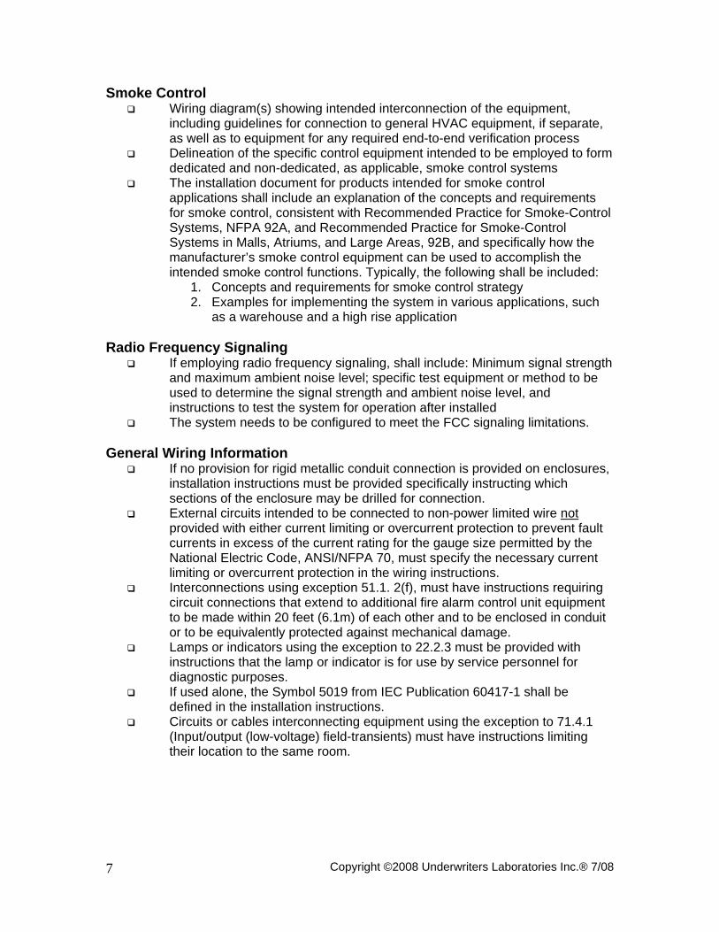
Smoke Control Wiring diagram(s) showing intended interconnection of the equipment,
including guidelines for connection to general HVAC equipment, if separate, as well as to equipment for any required end-to-end verification process
Delineation of the specific control equipment intended to be employed to form dedicated and non-dedicated, as applicable, smoke control systems
The installation document for products intended for smoke control applications shall include an explanation of the concepts and requirements for smoke control, consistent with Recommended Practice for Smoke-Control Systems, NFPA 92A, and Recommended Practice for Smoke-Control Systems in Malls, Atriums, and Large Areas, 92B, and specifically how the manufacturer’s smoke control equipment can be used to accomplish the intended smoke control functions. Typically, the following shall be included:
1. Concepts and requirements for smoke control strategy 2. Examples for implementing the system in various applications, such
as a warehouse and a high rise application Radio Frequency Signaling
If employing radio frequency signaling, shall include: Minimum signal strength and maximum ambient noise level; specific test equipment or method to be used to determine the signal strength and ambient noise level, and instructions to test the system for operation after installed
The system needs to be configured to meet the FCC signaling limitations. General Wiring Information
If no provision for rigid metallic conduit connection is provided on enclosures, installation instructions must be provided specifically instructing which sections of the enclosure may be drilled for connection.
External circuits intended to be connected to non-power limited wire not provided with either current limiting or overcurrent protection to prevent fault currents in excess of the current rating for the gauge size permitted by the National Electric Code, ANSI/NFPA 70, must specify the necessary current limiting or overcurrent protection in the wiring instructions.
Interconnections using exception 51.1. 2(f), must have instructions requiring circuit connections that extend to additional fire alarm control unit equipment to be made within 20 feet (6.1m) of each other and to be enclosed in conduit or to be equivalently protected against mechanical damage.
Lamps or indicators using the exception to 22.2.3 must be provided with instructions that the lamp or indicator is for use by service personnel for diagnostic purposes.
If used alone, the Symbol 5019 from IEC Publication 60417-1 shall be defined in the installation instructions.
Circuits or cables interconnecting equipment using the exception to 71.4.1 (Input/output (low-voltage) field-transients) must have instructions limiting their location to the same room.

Copyright ©2008 Underwriters Laboratories Inc.® 7/08 8
General Wiring Information, continued If duplicate terminals are not provided to facilitate supervision of installed
wiring connections (examples include: where the control unit is acting as the initiating device via alarm contacts, the NAC or power input to a NAC Extender or control module, etc.) and there is no provision to prevent looping an unbroken wire around or under a terminal the word “CAUTION” and the following or equivalent text shall be included “FOR SYSTEM SUPERVISION-FOR TERMINALS__AND__, DO NOT USE LOOPED WIRE UNDER TERMINALS. BREAK WIRE TO PROVIDE SUPERVISION OF CONNECTIONS.” The blanks are filled in with the applicable terminal identification. The marking is not needed for circuits that provide supervision without the need for duplicate terminals.
If for field wiring: If a special tool is required for connection, use identified by name of mfr. and model; range of wire sizes; and when means for testing for open and ground fault is not incorporated in the unit, a means shall be indicated.
Mounting position is to be indicated if critical to proper function If terminals with nor intended connection are provided, mark them NC or
equivalent (S527 only) Wiring methods should be in accordance with the Canadian
Electrical Code, C22.1, Part 1, Section 32 Separation of Circuits
When the product design is such that the product requires or permits power-limited circuit conductors to occupy the same enclosure as non-power limited conductors, specific wire routing configurations must be detailed that ensure a minimum ¼ inch spacing be maintained between the different circuit type conductors (see 12.3.1)

Copyright ©2008 Underwriters Laboratories Inc.® 7/08 9
2. OPERATION
INSTRUCTIONS FOR USE This section covers the intended application of the product. The list may not be inclusive. This information can be presented in different formats provided it is comprehensive.
System types
Local Emergency relocation (paging)
Live Pre-recorded
Emergency communication (telephone) Local with shunt Protected premise unit
Auxiliary Central station Proprietary Remote station SIA CP-01-2000
Supervising station unit Auxiliary (Public Fire Alarm Reporting System) Central station Proprietary Remote station
Communication transmission path Coded Non-coded Reverse polarity Multiplex
Type 1 Type 2 Type 3 No line security Standard line security Encrypted line security
Two way private radio Type 4 Type 5 No line security Standard line security Encrypted line security
One way private radio Type 6 Type 7 No line security Standard line security Encrypted line security

Copyright ©2008 Underwriters Laboratories Inc.® 7/08 10
System types, continued DACT
No line security Standard line security Encrypted line security
DACR DART DARR Other transmission technologies
No line security Standard line security Encrypted line security
Marine Releasing
Cross zone Counting zone Combination cross/counting zone NFPA 12, Carbon dioxide extinguishing systems NFPA 12A, Halon 1301 fire extinguishing systems NFPA 13, Sprinkler systems NFPA 15, Water spray fixed systems for fire protection NFPA 16, Foam-water sprinkler and foam-water spray systems NFPA 17, Dry chemical extinguishing systems NFPA 17A, wet chemical extinguishing systems NFPA 750 Water mist NFPA 2001, Clean agent fire extinguishing systems
Smoke Control NFPA 92A, Smoke control systems NFPA 92B, Smoke management systems in mall, atria and large areas Dedicated Non-dedicated Firefighters smoke control station (FSCS) Energy management
Process Control Critical Non-critical
Emergency signaling Type AM Type SM Type UM
Non-emergency (Type NM) Residential
Fire Security
Releasing device Smoke detector monitor (UL1730) Security
Proprietary Central station Access control Police station
Copyright ©2008 Underwriters Laboratories Inc.® 7/08 11
System types, continued Hold-up Local SIA CP-01-2000
Other

Copyright ©2008 Underwriters Laboratories Inc.® 7/08 12
3. FUNCTIONALITY
INSTRUCTIONS FOR USE This section addresses the intended function of the product. The list of functions below is an example only and is not intended to be inclusive. A section will follow that includes programming variables. It is not necessary to cover functionality in both the Functionality section and the Programming Option sections. For instance, automatic drift compensation would be covered here because no programming options would be available for that. On the other hand, AC delay might be covered under the Programming Option section because the delay time could be selectable. Any functionality information not covered under Operating instructions for normal standby, alarm, alarm test, alarm silence, alarm reset, trouble, trouble silence, off-normal position of switches, and functions of lights and switches needs to be covered here.
Drift compensation Remote programming Extent/limitations of synchronization
If cross zone or inter unit synchronization is applicable, details on the limitations and extent should be included.
When a system is intended to provide evac signaling to more than one notification zone, synchronization of the audible emergency evacuation signal pattern on a notification circuit basis in lieu of a system basis is acceptable. Specifics covering the installation constraints shall be clearly detailed
Calibrated detector sensitivity testing For products utilizing an automatic analog smoke detector sensitivity test
feature, the installation instructions shall specify the extent of the range of time intervals between activations of the automatic test feature.
Multiple detection operation for evacuation Units employing the multiple detector operation described in 55.3.1 and
55.3.2 shall include guidelines for installing of a minimum of two detectors in each protected space and to reduce the detector installation spacing to 0.7 times the linear spacing in accordance with National Fire Alarm Code, NFPA 72.
Positive alarm sequence Pre-signal Alarm verification Two wire compatibility
An indication when a product is intended to handle detectors with optional features or a product is intended to handle more than one detector in the alarm condition shall be included.
A stipulation that detectors of different models are not to be mixed or matched on a system, unless the system is specifically intended to be installed in that configuration. When mixing is permitted, specific limitations shall be included. This information can alternatively be included in the Compatibility section.

Copyright ©2008 Underwriters Laboratories Inc.® 7/08
3. FUNCTIONALITY, continued
Supervisory signal operation For products whose operation provide the capability of selecting
nonautomatic distinctive restoration-to-normal supervisory signals (locking in the supervisory signals until manually reset) the document should include instructions or details for selecting the respective operation.
Manual release/abort switch interaction The installation instructions for a control unit for releasing service shall
describe whether the operation of the manual release will override an activated abort switch.
NAC reactivation (alarm resound) When a system is intended to provide signaling service to two or more
physically separated buildings or zones, reenergization of the notification appliance circuits only on a zone basis meets the intent of the requirement. Specifics covering installation constraints shall be clearly detailed in the control unit installation wiring diagram/instructions. Systems are also not prohibited from having provision to automatically disable reenergizing alarm notification circuits due to subsequent activation of other addressable smoke detectors of the same type located in the same room or space as the initial activated device. Specifics should be clearly detailed.
DACR check in A DACR intended only for central station service is not required to
automatically annunciate, display, and record delinquency signals when marking on the product or in the installation wiring diagram/instructions clearly indicate the need to manually track the signaling performance of each DACT and failure to receive a signal from a DACT over the applicable period is to be handled as a trouble signal.
Primary power source failure The primary power source failure of constantly attended supervising-
station equipment, for methods to determine when the fault condition is obvious to the operator on duty is covered in the instructions.
DAC communication format SIA Contact ID SK 4/2 3/1 Other ___________
Interconnected control panels Unless interconnected control units located at a protected premises are
intended to be installed such that the display annunciation at each unit can be simultaneously observed, alarm, supervisory, and trouble conditions, as well as reset, alarm silence, or trouble silence actuation originating at any unit shall be annunciated at each control unit and non-supplementary operator interface.
Walk test Integrated/network local functionality Circuit disables

Copyright ©2008 Underwriters Laboratories Inc.® 7/08 14
3. FUNCTIONALITY, continued
Mapping Detection/alarm algorithms Day/night sensitivity Detection sensitivity adjustment Extent/limitations of combination system
Ability to partition security only Arming/disarming Priority of signals

Copyright ©2008 Underwriters Laboratories Inc.® 7/08 15
4. PROGRAMMING OPTIONS
INSTRUCTIONS FOR USE
This section addresses ALL of the available programming options for the product. The list of programming options is an example only and is not intended to be inclusive. The previous section includes functions. It is not necessary to cover programming options in both the Functionality section and the Programming Option sections. For instance, automatic drift compensation would be covered in the Functionality section because no programming options would be available for that. On the other hand, AC delay might be covered here because the delay time could be selectable. The information can be presented as shown in the example or in some other format as long as the required information is present.
Where the field-programmable software of a product contains both complying as well as non-complying features or parameters as permitted in 54.1.2, the following (or equivalent presentation) shall be included in the front of the programming manual or the beginning of the program section of the installation manual:
NOTICE TO USERS, INSTALLERS, AUTHORITIES HAVING JURISDICTION
AND OTHER INVOLVED PARTIES: This product incorporates field-programmable software. In order for the product to comply with the requirements in the Standard for Control Units and Accessories for Fire Alarm Systems, UL 864, certain programming features or options must be limited to specific values or not used at all as indicated below. Additionally, the information in 90.23 shall also appear throughout the manual where the specific feature or option appears describing the requirements of this standard.
Topic Feature or Option Permitted in UL? (Y/N)
Possible Setting(s) Setting(s) Permitted in
UL864?
Comment
IDC Zone type Y Heat, cold, water, waterflow, supervisory, AC delay
Y
NAC Cadence Y Constant, March code, Company ABC sync., ANSI S-3.41 code
Y
NAC Pre-alarm Y Select NAC Y NAC Fire drill Y Select NAC Y Relay Aux relay Y Select Relay Y Misc. AC Delay Y 0-24 hrs. Y IDC Zone response Y 0.5 – 1 sec. Y NAC Selectable silence Y Different zones Y DAC # of attempts Y 1-5 Y DAC Test signals Y 0-24 hours Y DAC Dial attempts per
line Y 3-5 Y
Smoke Automatic test Y weekly Y Dedicated

Copyright ©2008 Underwriters Laboratories Inc.® 7/08 16
5. TESTING / MAINTENANCE
INSTRUCTIONS FOR USE This section provides a brief description of the testing and maintenance for the system. Following is the minimal information that needs to be included here. Any testing/maintenance issues not covered under the Operating Instruction section need to be included here. Information does not need to be included in both sections.
Description of the maintenance procedures of the system. This shall include, as applicable, the following:
Fuse replacement Primary battery replacement (reference to a specific replacement part which
must be used with the product shall be indicated; instructions to replace batteries periodically; the period specified shall not be greater than the useful life of the battery, which has been determined by test)
Rechargeable battery maintenance and replacement (where a rechargeable battery is used, proper maintenance and testing procedures shall be described)
“Replace battery with (battery manufacturer’s name or end product manufacturer’s name, part number) only. Use of another battery may present a risk of fire or explosion.” if the product uses a user-replaceable lithium battery and is marked adjacent to the battery “See operating or maintenance instructions for type of battery to be used” because a bigger marking is not feasible.
If a lithium battery is used by the product, complete instructions on how to replace and dispose of a used battery are provided including; a) a warning notice stating the following or equivalent “CAUTION – The battery used in this device may present a risk of fire or chemical burn if mistreated. Do not recharge, disassemble, heat above 100 degrees C (212 degrees F), or incinerate. Replace battery with (battery manufacturer’s name or end product manufacturer’s name and part number) only. Use of another battery may present a risk of fire or explosion.”, b) Complete instructions as to how to replace the battery ending with the statement: “Dispose of used battery promptly. Keep away from children. Do not disassemble and do not dispose of in fire.”
Maintenance recommendations Description of the testing procedures of the system (this shall include periodic
testing recommendations). (S527 only) All test and maintenance instruction codes and software
necessary to provide test and inspection requirements of CAN/ULC-S536, Standard for the Inspection and Testing of Fire Alarm Systems

Copyright ©2008 Underwriters Laboratories Inc.® 7/08 17
6. COMPATIBILITIES
INSTRUCTIONS FOR USE This section addresses other devices that can be connected to form the system to meet the intended application. The list is an example only and is not inclusive.
NAC Appliances
Manufacturer Model/Family # per Circuit (If sync. is an issue)
ABC Mfg. XYZ Yes Initiating Devices Two Wire Smoke Detectors (Compatibility ID for panel of module)
Manufacturer Model Comp. ID (Head)
Comp. ID (Base)
# per Loop
ABC Mfg. XYZ DEF GHI 20 Releasing Circuit
Manufacturer Model Type Max. # ABC Mfg. XYZ Solenoid 1
Supplementary Devices
Manufacturer Model Type ABC Mfg. XYZ Monitor
SLC Circuits
Manufacturer Model Type ABC Mfg. XYZ Smoke detector
DACT/DACR Compatibility
Manufacturer Model Compatible Formats ABC Mfg. XYZ SIA 20
Power Output Circuit Devices Door Hold Release Devices
Manufacturer Model Compatible Door Holder ABC Mfg. XYZ UVW
Emergency Exit Locks
Manufacturer Model ABC Mfg. XYZ
Four Wire Smoke Detectors
Manufacturer Model ABC Mfg. XYZ

Copyright ©2008 Underwriters Laboratories Inc.® 7/08 18
7. SYSTEM CONFIGURATION
INSTRUCTIONS FOR USE This section covers the configurations needed to meet the intended applications. The minimum and optional configurations are to be included here. The list is an example only and is not inclusive.
Accessory/ Subassembly
Part No. Description Local Remote Station(Rev. Pol.)
Proprietary Auxiliary Remote Station(DACT)
Releasing Service
ABC 123 Enclosure Y Y Y Y Y Y DEF Note 5 Enclosure 0 0 0 0 0 0 GHI 456 Main control module Y Y Y Y Y 7 JKL 234 OEM power supply Y Y Y Y Y Y BCD 345 220 V ac power supply Y Y Y Y Y Y CDE 567 Display/switch module Y Y Y Y Y Y EFG 678 Signature expansion loop 0 0 0 0 0 7 FGH (note 1) 789 Reverse polarity module 0 y 0 0 Y 0 HIJ 891 16 red LED annunciator 0 0 0 0 0 0 IJK 890 16 yellow LED annunciator 0 0 0 0 0 0 JKL (note 2) 901 Coder module 0 0 0 0 0 0 KLM (note 2) 012 Isolated RS-232 module 0 0 0 0 0 0 LMN (note 3) 091 Local Energy Master Box Module 0 0 0 0 0 0 MNO 098 Coder 0 0 0 0 0 0 NOP Audio controller 0 0 0 0 0 0 OPQ Paging microphone 0 0 0 0 0 0 PQR Firefighters telephone 0 0 0 0 0 0 QRS 987 Isolator module 0 0 0 0 0 0 RST 876 Data line monitor 0 0 0 0 0 0 STU 765 Main Control Module 0 0 0 0 0 0 TUV+ - City of Chicago 0 0 0 0 0 0 UVW - Display/Switch Module 0 0 0 0 0 0
+ - Separately Listed Subassembly

Copyright ©2008 Underwriters Laboratories Inc.® 7/08
7. SYSTEM CONFIGURATION, continued Accessory/ Subassembly
Part No. Description Local Remote Station (Rev. Pol.)
Proprietary Auxiliary Central Station
Remote Station (DACT)
Releasing Service
VWX 654 Power supply Y Y Y Y Y Y Y WXY 543 220 V ac power
supply Y Y Y Y Y Y Y
XYZ 432 DACT O O O O Y Y 0 YZA Note 5 Enclosure Y Y Y Y Y Y Y ZAB Note 6 Audio
Enclosure O O O O O O 0
ZYX
(Note 4)
321 2-wire smoke module
O O O O O O 0
XWV Note 6 Amplifier O O O O O O 0 WVU Note 6 Amplifier with
tone/mic O O O O O O 0
Notes:
Y - Yes
N - No
O - Optional
Note 3: Requires the separately Listed Model XPQ module.
Note 4: Requires the separately Listed Model JAY module.
Note 5: One enclosure power BES1 or BES2 system must be used.
Note 6: Enclosure designed to house separately Listed BES1 or BES2 Series audio system. Must use 1 piece AC123, and one of the following amplifiers; AA123, AA345, or AA567.
Note 7: Requires minimum of one Listed Model, KBG module.

Copyright ©2008 Underwriters Laboratories Inc.® 7/08 20
8. SYSTEM POWER / SIZE
INSTRUCTIONS FOR USE This section covers the primary and secondary system power limitations. It also covers the limitations on maximum capacity for modules, appliances, etc. for addressable devices, modules, subassemblies, and network panels. The following is an example and is not inclusive.
System Power
Power Current Max. AH capacity
Derating factor*
Max. standby current
Max. alarm current
Max. standby time
Max. alarm duration
Primary (power supply)
6A N/A N/A 1.1 A 6A N/A N/A
Secondary (back up)
6A 35 AH 10% 1.1 A 6 A 24 hrs. 5 min.
* Products complying with 63.1.3 shall include a minimum secondary (standby)
battery derating value of 10%, when specifying required standby capacity. System Size
Accessories/subassemblies/networked panels Maximum system capacity Monitor modules 198 Initiating Device Circuit cards 4 Control modules 98 Model XYZ fire alarm control panel 64 nodes

Copyright ©2008 Underwriters Laboratories Inc.® 7/08 21
9. OPERATING INSTRUCTIONS
INSTRUCTIONS FOR USE The description of the product operation is intended to be a brief summary of the details for an operator – details beyond the summary need to be in the Functionality section. The description of system maintenance procedure is intended to be a brief summary of the maintenance – details beyond the summary need to be in the Testing/Maintenance section.
A control unit that is not intended to have an operator in attendance shall be provided with simple operating instructions. These instructions shall be on the cabinet front or on a separate sheet that can be framed and located adjacent to the control unit. When they are separate from the control unit, the instructions shall include the model number of the control unit and be referenced in the control unit marking by number and issue number and/or date. The instructions shall include a capsule description of pertinent conditions applicable to the particular control unit as follows:
Description of the product operation. This shall include, as applicable, the following:
1. Normal standby 2. Alarm 3. Alarm test 4. Alarm silence 5. Alarm reset 6. Trouble 7. Trouble silence 8. Off-normal position of switches 9. Functions of lights, audible indicators or switches
Description of the maintenance procedures of the system. This shall
include, as applicable, the following: 1. Fuse replacement 2. Primary battery replacement (reference to a specific replacement part
which must be used with the product shall be indicated; instructions to replace batteries periodically; the period specified shall not be greater than the useful life of the battery, which has been determined by test)
3. Rechargeable battery maintenance and replacement (where a rechargeable battery is used, proper maintenance and testing procedures shall be described)
4. Maintenance recommendations