Embed Size (px)
Citation preview

1
THERMAL ENERGY STORAGE FINAL PRESENTATION
Robert S. Wegeng (PI) James H. Saunders (Co-PI) Christopher J. Pestak Ioan I. FeierPaul HumbleFebruary 3, 2009
Lunar Surface Systems Concepts Studies

2
TER System Concept
Reflector
Collector
HTTER LTTER
Solar shield
RadiatorHeat
engine
Qh QL
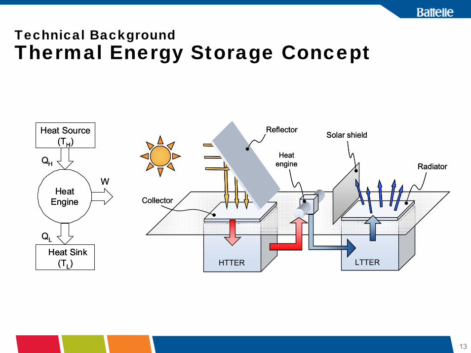
TER – Thermal Energy ReservoirHTTER – High Temperature Thermal Energy ReservoirLTTER – Low Temperature Thermal Energy Reservoir

3
Reference TER System Conceptual Design for Polar Outpost
• Makes use of Altair Lander propellant tanks• Makes use of ISRU byproducts (e.g. from
O2 generation)• Requires no reactants to be brought from
Earth• Net power generation capacity: 2.0 kWe• Net Power Density: ~10 watts/kg
4
Outline
• Introduction• Battelle Overview• Technical Background• Analytical Support for Reference System
Conceptual Design• Alternative Radiator Concept• Additional Applications of Lunar TERs (Not part of
Contract Scope)• Conclusions

5
Purposes outlined in Will:
Why We Do What We Do –Battelle’s Beginnings
5
• Founded by Will of Gordon Battelle in 1929 as a non-profit, charitable trust to provide “the greatest good to humanity”
• Governed by a self-perpetuating Board of Directors
• Interprets Will in light of today’s needs and conditions
• “Creative and research work”
• “Making of discoveries and inventions”
• Better education of men and women for employment
• Societal and economic impact

6
• Metals and materials including armor plating for U.S. tanks in WWII
• Fuel for Nautilus, the first nuclear submarine
• Xerography• Early compact disc technology• Fiber-optics technology for
telecommunications• Increased fuel cell performance and
fuel cell materials• Affordable clean water purification• Drug delivery technology• Threat detection for
people/infrastructure
What We’ve Done –Where We’ve Been
• Developed new materials
• Improved and created entire industries
• Pioneered new technologies
6

7
Why We Do What We Do –Community Benefit
7
• “Simultaneous Excellence” and “Community Benefit” are “bookends” of Battelle operations
• We are redefining how the “engaged corporation” interacts with the community
• We promote STEM (science, technology, engineering, and math) education through local, regional, and national programs– Emphasis on STEM education will
ensure nation’s competitive edge and help sustain our quality of life
• “Portfolio” approach focusing on education, the arts, health and human services, and economic development
• Staff-driven “Team Battelle”volunteer program
• Strategic philanthropy is integrated in Battelle’s business model

8
Large Company & Vision
Large Network of People and Technology
Large Opportunity to Make More Impact

9
Technical BackgroundBob Wegeng
Battelle - PNNL
10
Technical BackgroundRequirements
• 2 to 5 kWe net discharge electric power• 100 to 2000 kWe-hr net energy storage per module• TRL 6 by 2015 – 2018 timeframe• Operational life of 10,000 to 15,000 hours• 100 to 2000 charge/discharge cycles• Ability to withstand high dust, radiation and widely
varying thermal environment

11
Motivations
• Thermal Energy Reservoirs utilize the diurnal cycle of the Moon to generate electricity– Temperature swings of ~100 K to ~400K (equatorial
regions)– With concentrated solar energy, the high temperature
reservoir can be made to be hotter
• The majority of the mass of a lunar TER is already on the Moon

12
Motivations• Synergistic with other lunar
assets/programs– Considers using processed
lunar regolith, a byproduct of ISRU, as thermal mass material
– Considers using Altair Descent Stage propellant tanks to house thermal mass
– Considers use of high efficiency Stirling Cycle heat engine- International Lunar Network- Terrestrial solar-thermal power
generationCourtesy of Infinia Corporation
13
Technical BackgroundThermal Energy Storage Concept
Reflector
Collector
HTTER LTTER
Solar shield
RadiatorHeat
engine
Qh QL
Reflector
Collector
HTTER LTTER
Solar shield
RadiatorHeat
engine
QhQh QLQL
Heat Source(TH)
Heat Sink (TL)
Heat Engine
QH
QL
W
Heat Source(TH)
Heat Sink (TL)
Heat Engine
QH
QL
W

14
Technical BackgroundThermal Mass (TM) Materials
• Native lunar regolith is a poor thermal mass material– Thermal properties similar to fiberglass insulation
• Regolith can be processed to yield improved thermal properties
THERMAL PROPERTIES
Density Specific Heat Thermal
Diffusivity
Thermal Interaction
Distance over 354 hours
MATERIAL (kg/m3) (J/kg-K) (m2/sec) (m)Native Lunar Regolith 1.8 x 10³ 8.40 x 10² 6.6 x 10⁻⁹ 0.183Solid Basalt Rock 3 x 10³ 8.00 x 10² 8.7 x 10⁻⁷ 2.11 Common Brick 1.92 x 10³ 8.35 x 10² 4.49 x 10⁻⁷ 1.51

15
Technical BackgroundThermal Mass Production Methods
• Compaction and sintering (e.g., microwave sintering)• Melting processed or unprocessed regolith, then solidifying
the melt into a solid block
Heat TransferFluid In
Heat TransferFluid Out
Spherically-ShapedThermal Masses
Fill Port forThermal Masses
Tank(Brought From Earth)
• Incorporating hardware and/or materials with high thermal conductivity and/or high thermal capacity (e.g., heat pipes, phase-change materials)
• Reducing regolith by thermochemical or electrochemical means, to produce a metal-enriched product

16
LSAM/Altair Descent StageLOX/H2 Tank Volume Estimates
16
Tank Void Volume* Thermal Mass Capacity
m3 m3 kg kw-hrt per 100 C
1 O2 tank 5.655 3.393 8143 185.5
1 H2 Tank 16.745 10.047 24,113 549.2
1 H2 tank + 1 O2
tank22.40 13.44 32,256 734.7
2 H2 tanks 33.49 20.094 48,256 1098.5
2 H2 tanks + 1 O2
tank39.145 23.487 56,369 1284.0
2 H2 tanks + 2 O2
tanks44.8 26.88 64,512 1469.4
* Provided by Kriss Kennedy and Gary Spexarth, email 12/11/2008

17
Example Capacity Calculation (Approx)
• What power level can be obtained while extracting heat in a way that decreases the temperature of the HT TER by 100 C?
• Assume 1 H2 tank + 1 O2 tank32,256 kg thermal mass734.7 kw-hrt per 100 C
• Assume 20% efficient heat engine operating for 52 hours, with 90% shaft-work to electricity efficiency
Power = 734.7 kw-hrt x 0.20 / 52 hours = 2.83 kWshaft work
= 2.54 kWe
18
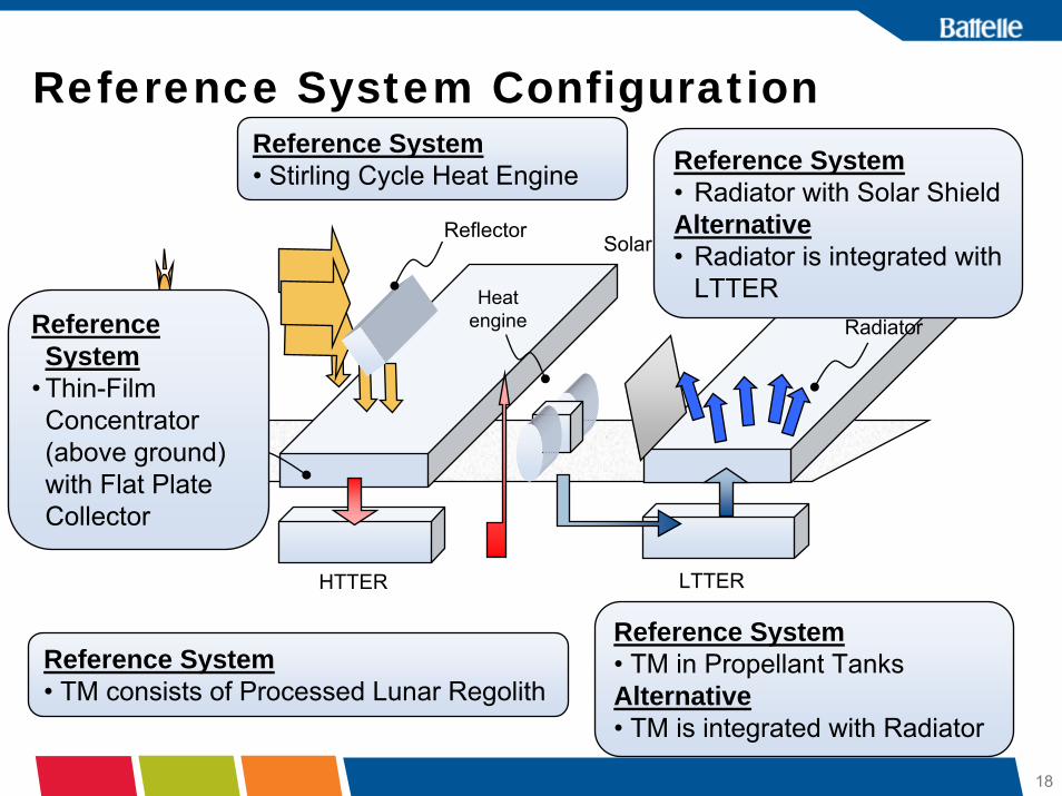
Reference System Configuration
Reflector
Collector
HTTER LTTER
Solar shield
RadiatorHeat
engine
Qh QL
Reference System• Radiator with Solar ShieldAlternative• Radiator is integrated with
LTTER
Reference System• Stirling Cycle Heat Engine
Reference System
• Thin-Film Concentrator (above ground) with Flat Plate Collector
Reference System• TM in Propellant TanksAlternative• TM is integrated with Radiator
Reference System• TM consists of Processed Lunar Regolith

19
Analysis Supporting Reference Conceptual
DesignJim Saunders
Battelle - Columbus

20
Analytical Approach
• Goal: Develop system models to estimate mass, volume and performance of thermal energy storage module based power systems for the lunar night.
• System models– Lumped parameter models based upon component
description- Subsytem or component models or parameterizations
– Simulate charging of the TER during the lunar daytime and power generation during the night.
• Calculations with encouraging power densities.

21
Thermal storage advantage• Compare two energy storage
approaches:– 1) launch mass is mainly
proportional to stored energy (P*t).- Batteries - Fuel cells
– 2) launch mass is mainly proportional to required power- Regolith thermal storage with heat
engine
• In other words imagine two different systems such that b1 and a2 are small (relative to b2 and a1, respectively)
PbtPam ⋅+⋅⋅= 222
PbtPam ⋅+⋅⋅= 111
power *constant time*power *constant mass +=
small
small

22
Thermal storage advantage
• Constants a & b will never be negative since masses are always positive• Pick 50% light to dark ratio, square wave, where 2*t is the period of a light and dark
cycle• For some value of t, the regolith thermal approach will have less launch mass• Conclusion: for long dark periods regolith energy storage is attractive
PbtPam ⋅+⋅⋅= 111
Launchmass
t
Duration of night, or of shadow
PbtPam ⋅+⋅⋅= 222
Batteries
Regolith thermalLower is better
Batteries are favorable Regolith thermal is favorable
t = ?
23
System Configuration
• Non-polar region: 348 hr day and night– Easiest first calculation
• South Pole Shackleton Crater: – 52 hr max night. Simulations with 52 hr day and night. – Seasonal simulations: more complex.
• Assume 2 kWe, 90 % power electronics efficiency, 200 W parasitics, which yields 2440 W shaft power.

24
ConfigurationsReflector
Collector
HTTER LTTER
Solar shield
Radiator
Qh QL
PHeat engine
Reference case: Reflector, collector, HTTER, Carnot engine, radiator.
•No LTTER
•Alternate case: LTTER found favorable in previous work.
•Start with generally ideal assumptions for example calculations.
•Optimized the collector and radiator area for each HTTER, LTTER combination.

25
Solar Collector• Flat plate heat exchanger
– Assume two 1 mm Al sheets: Allowable stresses suggest that < 1 mm is sufficient. Previously we used 3 mm.
– H2 heat transfer gas from collector to HTTER.– Selective surface. Absorptivity =.9, IR emissivity = 0.1– Flat, located at the side of the HTTER.
• Reflector directs sunlight to the heat exchanger– Assume a 1mm Al sheet with 10 kg for tracking drive and 10 kg for
supports.– Area=1.2*Concentration Ratio * Area Collector. Reflector and
concentrator are combined for our low concentration ratios.– Results in 2.7 kg/m2
- Kohout (1991) used 2.48 kg/m2 for a PV array including tracking, wiring, frame
- Freeh (2008) used 2 kg/m2 for a PV array with 10 kg for drive and 10 kg for supports.

26
Solar Collector (cont’d)
• What is the maximum temperature of this collector?
• Ignoring radiation back to the sun:
• CR is the concentration ratio.• For the maximum temperature, q=0, and
T=680 K for a concentration ratio of 1, and T= 809 K for CR=2.
( )44ambsun TTCRqq −−= σεα
0 1 2 3 4 5 6 7 8 9 100
200
400
600
800
1000
1200
1400
T CR( )
CR

27
Advanced Concentrated Collectors• We have considered flat plate
collectors with reflectors that concentrate light.– The collectors see a large fraction
of deep space for reradiation.
• Concentrated collectors, at the back of a cavity:– See more sun for reradiation,
reducing thermal losses.– We have neglected this effect in
our simulations
• More advanced concentrating collectors should be explored in future work.

28
Processed Regolith Properties
• Uncertainty in properties. Varies with lunar location.• Processed regolith - Used correlations of Colozza (1991), based on Apollo 17
data.– Density: VF3000 kg/m3, pick VF=0.9
– Specific heat (assumed to be the same for processed and native):- C = -1848.5 + 1047.41* log(T) J/(kg*K)- Note that for T<58.2 K this fit yields C<0 which is physically unrealistic
– Thermal conductivity was not needed in the system model. For component models, constant values and temperature dependent functions were both used.
• Discussed regolith properties with GRC staff. Simulants are available for native regolith. Not much available on processed regolith.
29
High Temperature Thermal Energy Reservoir• For the system model, assumes a thermal mass maintained at a uniform
temperature by the flow of heat transfer fluid through the regolith.• Component models examined this more carefully.
– Regolith spheroids arranged within the propellant tank• Assume the HTTER is a cube of dimension L, surrounded by a radiation
shield blanket.– Blankets are in use that have effective emissivities ≈ .001 - .005.– Protects against micrometeoroids, charge accumulation, plume impingment,
corrosion, etc. Charging control may help with dust repression.
• Radiation shield mass is included, but approximate. Assumed equivalent to 2 Al sheets, 0.1 mm thick.
• Neglected heat loss in our simulations, except for one seasonal simulation.
• The collector sits on top and has an area, Ac.

30
Heat engine
• Carnot engine, K = 1.
⎟⎟⎠
⎞⎜⎜⎝
⎛−=
H
Lengine T
TK 1η
• Assumed 100 W/kg for engine, based upon discussions at GRC
•Stirling engine•K≈0.6 over a wide temperature range.
•Reviewed Stirling performance & W/kg, with GRC.
•Usual operating temperature range: TL≈323 K.
•Assume engine shuts down for TH/TL < 1.25.
•For TL = 300 K, TH = 800 K, ηengine = 37.5 %

31
Stirling Technology• Example: Lee S. Mason, “A Comparison
of Fission Power System Options for Lunar and Mars Surface Applications, NASA/TM-2006-214120
• 50 kW electrical output scenario• Stirling system has the lowest system
mass and best specific power– TE: 6.0 W/kg– Brayton: 8.8 W/kg– Stirling: 9.4 W/kg
• Stirling system has best overall efficiency (Pout/Psource)
– TE: 4.3%– Brayton: 13.9%– Stirling: 19.0%
• Stirling has broad operating range and can function effectively over temperature ratios as low as 2.0-2.5
•Stirling: 60 % Carnot for 3 > TH/TL > 2
•Brayton: 40 % Carnot for 4 > TH/TL > 3
•Thermoelectric: < 20 % Carnot for 2 > TH/TL > 1.5
•Stirling: ~ 100 W/kg
•(Mason and Schreiber, 2007)
•Stirling has run to TH/TL ≈ 1.5. Assumed 1.25 for the analysis. No upper limit.

32
Radiator
• Two 1 mm sheets of Al• Area density of 5.3 kg/m2.• 5 kg/m2 used by others (Kohout, 1991; Freeh, 2008)• Sink temperature assumed to be 10 K, with one side of active area.• Mason has looked at vertical two-sided radiators with higher effective sink
temperatures.• Inflatable radiators ~ 1 kg/m2 (Wong, GRC).
• We propose an additional radiator concept.
33
Low temperature thermal reservoir
• Can reduce radiator size• In contrast to HTTER, we want to maximize heat loss. This implies large
surface to volume ratio and low surrounding temperatures.• Located in the shadows or cooled by heat rejection to dark sky at ≈ 10 K.
– Summer or winter.
• Assumed to start at 150 K.• Shadowed base of Shackleton crater ≈ 90 K, according to recent
Japanese measurements.
34
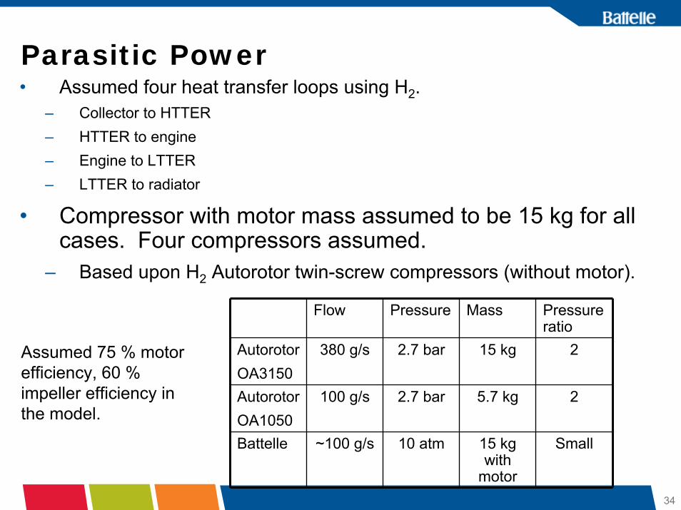
Parasitic Power• Assumed four heat transfer loops using H2.
– Collector to HTTER– HTTER to engine– Engine to LTTER– LTTER to radiator
• Compressor with motor mass assumed to be 15 kg for all cases. Four compressors assumed.
– Based upon H2 Autorotor twin-screw compressors (without motor).
Flow Pressure Mass Pressure ratio
AutorotorOA3150
380 g/s 2.7 bar 15 kg 2
AutorotorOA1050
100 g/s 2.7 bar 5.7 kg 2
Battelle ~100 g/s 10 atm 15 kg with
motor
Small
Assumed 75 % motor efficiency, 60 % impeller efficiency in the model.

35
Parasitic Power (cont’d)
d
• Mixtures of H2 - N2 or H2 - Xe, etc may give lower parasitic losses.
• Water could be used in the low temperature loops if the radiator temperature is held above 273 K.
x( )4.f L⋅
π ρ x( )2
⋅ Pwr⋅
Qcollcp x( ) DT⋅
⎛⎜⎝
⎞⎟⎠
3
⋅⎡⎢⎢⎣
⎤⎥⎥⎦
15
:=
0 0.2 0.4 0.6 0.81
1.5
2
2.5
3
3.5
425 W at 10 atm with H2-N2 mixture
Mole fraction H2
Pipe
dia
met
er
d xi( )in
xi

36
Parasitic Power (cont’d)
• Mass of heat transfer fluid: H2 for HTTER, H2 or water for LTTER?– Volume of HTTER = 16.75 m3
– Assume 40 % void fraction– Mass of H2 at 10 atm required for HTTER tank = 2.33 kg– Volume of LTTER = 10,000/2700*.4/.6 = 2.5 m3
– Mass of water required: 2,500 kg– Mass of H2 required: 2 kg– Therefore we selected H2 for the base case in both the HTTER and
LTTER.– Mass of H2 is neglected in system calculations

37
Piping Lengths
LR
LC
LLTTRLHTTR
Stirling & loop pump package
HTTRLTTR
Radiator
Collector
Solar collector to HTTR fluid loop pipe length: 2CL
HTTR to hot side of Stirling engine fluid loop: ( )12 +HTTRL Cold side of Stirling to LTTR fluid loop: ( )12 +LTTRL LTTR to radiator fluid loop: 2RL
38
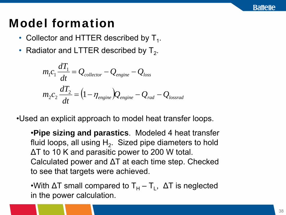
Model formation• Collector and HTTER described by T1.• Radiator and LTTER described by T2.
( ) lossradradengineengine
lossenginecollector
QQQdt
dTcm
QQQdtdTcm
−−−=
−−=
η1222
111
•Used an explicit approach to model heat transfer loops.
•Pipe sizing and parastics. Modeled 4 heat transfer fluid loops, all using H2. Sized pipe diameters to hold ΔT to 10 K and parasitic power to 200 W total. Calculated power and ΔT at each time step. Checked to see that targets were achieved.
•With ΔT small compared to TH – TL, ΔT is neglected in the power calculation.
39
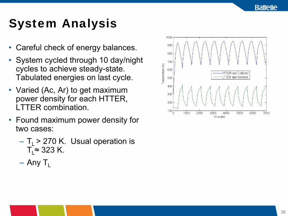
System Analysis
• Careful check of energy balances.• System cycled through 10 day/night
cycles to achieve steady-state. Tabulated energies on last cycle.
• Varied (Ac, Ar) to get maximum power density for each HTTER, LTTER combination.
• Found maximum power density for two cases: – TL > 270 K. Usual operation is
TL≈ 323 K.– Any TL

40
Overall Power Density
• Each point represents an optimized power density with collector and radiator area as the independent variables.
• 10,000 kg low temperature reservoir for all cases.
• Power is the shaft power (2440 W), not the net electrical power (2000 W).
• Parasitic power is roughly sized for 200 W, but some cases go up to 380 W.
• Temperature drop in heat transfer loops is about 10 K and is neglected in the performance calculation, but is included for the parasitic power.

41
Comparison of Masses
Any Radiator Temperature
Radiator Temperature > 270
52 hr day and night, Conc R = 1
30,000 kg HTTER
348 hr day and night, Conc R = 4
20,000 kg HTTER.

42
Comparison of Temperatures and Heat Flows52 hr day and night, Conc R = 1
30,000 HTTER
348 hr day and night, Conc R = 4
20,000 kg HTTER.

43
Determination of Best (Ac, Ar)
• Note that the engine cannot deliver 2,440 W for all (Ac, Ar).
• Optimum is on the “edge of the cliff”.
• Smallest (Ac,Ar) that delivers the power is the best.

44
Effect of Radiator and Collector Temperatures• Radiator temperature is a key
variable.• Generally lower temperatures yield
higher power densities.• Red diamonds show temperatures
over 270. Blue diamond at (22,200) is the highest power density.
• Collector temperature is consistently near the maximum.
• The length of the solar daytime will also be important.
52 hr night, Conc Ratio = 1, 30,000 kg HTTER
348 hr night, Conc R = 4, 20,000 kg HTTER

45
Design Guidelines• Repeating day and night cases.• At steady state, EHTTER = P*t/ηeng
• Need just enough EHTTER to supply power• Need TH and TL such that the engine runs and with acceptable ηeng. TH/TL
> 1.25. For TL = 323, TH > 404K at the end of the night.• For engine efficiency = 30 %, TH=646 K• Collector (and THTTER) has a maximum temperature for a given
concentration ratio, which is usually just reached in optimal designs.– CR =1, TH = 680 K.– CR=2, TH = 809 K– CR=4, TH = 962 K
• Larger HTTER masses require larger collectors, longer pipes, more insulation, but have less temperature drop and thus require lower radiator area
46
Power Density Discussion• Power density = Power/Mass Carried• Power is fixed as long as the engine can deliver it.• Mass is the key variable.• Mass comments:
– Low density radiators and collectors could really help (We’re assuming 5.3 kg/m2 for the radiator, more for the collector– typical number is 5 (Kohout, Freeh). Inflatable radiators could be 1-2.
– Flow loop design is just roughed in. Assuming H2 for both fluids. H2/N2 or H2/Xe should be better.
– Reflector is significant. Now just assuming A=1.2*CR*Ac.

47
Radar interferometry digital elevation models (DEM) exist background image from http://lcross.arc.nasa.gov/docs/Allen.LCROSS%20talk.ppt#272,4,Slide 4 (Carlton Allen, NASA JSC)
Radar DEM
Shackleton crater
Shoemaker crater
Site A
Mount Malapert
Apparent sun motion
South pole
Overhead flight movie path
48
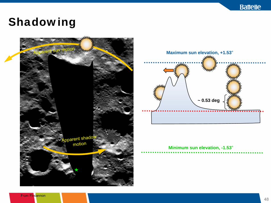
Shadowing
Apparent sun motion
~ 0.53 deg
From Fincannon
Maximum sun elevation, +1.53°
Minimum sun elevation, -1.53°Apparent shadow
motion

49
Shackleton rim illuminationIllumination fraction
0
0.2
0.4
0.6
0.8
1
1.2
1 710 1419 2128 2837 3546 4255 4964 5673 6382 7091 7800 8509
Time (hours)
Illum
inat
ion
fract
ion
Illumination fraction
Sun & Horizon Elevation
-5
-4
-3
-2
-1
0
1
2
3
1 710 1419 2128 2837 3546 4255 4964 5673 6382 7091 7800 8509
Time (hours)
Deg
rees
Sun elevation (degrees)Horizon elevation (degrees)
Sun, to approximate vertical scale

50
Solar Incidence Analysis
• Used data from J. Fincannon.• Consider night to be < 10 % sunlight.• Triggering algorithm (top) reveals one
50 + hour night. • Histogram shows distribution of night
time durations.
51
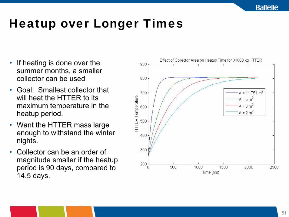
Heatup over Longer Times
• If heating is done over the summer months, a smaller collector can be used
• Goal: Smallest collector that will heat the HTTER to its maximum temperature in the heatup period.
• Want the HTTER mass large enough to withstand the winter nights.
• Collector can be an order of magnitude smaller if the heatupperiod is 90 days, compared to 14.5 days.

52
Seasonal Simulation• Can we increase the power density significantly?• Use GRC Shackleton data recommended by Jim Fincannon.• Heatup in summer. No power withdrawal.• As soon as sun drops below 10 % illumination - power on.• Very preliminary results: rapidly fluctuating data – unable to do
reliable energy balance checks. Could be wrong!• Heat loss expected to be important.• In this model, collector- HTTER flow remains on during nightime.
Collector radiates back to space, cooling the HTTER. In practice, the flow would shut off, cooling only the collector, which has low thermal mass.
53
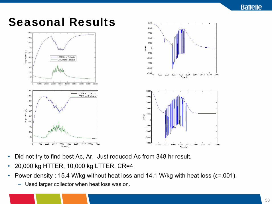
Seasonal Results
• Did not try to find best Ac, Ar. Just reduced Ac from 348 hr result.• 20,000 kg HTTER, 10,000 kg LTTER, CR=4• Power density : 15.4 W/kg without heat loss and 14.1 W/kg with heat loss (ε=.001).
– Used larger collector when heat loss was on.

54
Summary
52 hr day/night 348 day/nightPower Density (W/kg)
10.48 10.65
Mass Carried 233 230Engine 24.4 24.4Reflector 70.1 70.9Collector 41.7 21.2Insulation liner 10 15.9Piping, compressor, etc
73.6 75.9

55
Control Approaches
• For equal day and nights, assumed collector was covered with an insulated shade at night.
• For Shackleton, the sun flickers above and below the horizon. When does the power come on? How do we minimize heat loss?– One possibility. Use a low mass solar collector. Stop the H2 flow for
sufficiently long darkness periods.– Use model-based observers to forecast the darkness period.
Essentially fit an illumination model to real-time measurements to constantly update the model.
– Use model-based control to optimize performance and adjust for system changes: collector or radiator degradation, etc.
• Control of radiator temperature and holding the engine temperature ratio within acceptable bounds.

56
Recommended areas for future work• Low mass concentrator-reflector-collector with high collection efficiency.• Low mass radiator incorporating processed regolith• Processed regolith methods of production and properties.• Review status of gas compressor or blower for heat transfer loops.
Consider gas mixtures. Process design to minimize parasitics.• Lander tank modifications for use in thermal reservoirs.• Update model and optimize power density. Include heat transfer loops to
enable separate calculation of collector, HTTER, LTTER, and radiator temperatures.
• Determine operating temperatures for Stirling engine in this application.• Control schemes, especially model-based sensing and control.
57
Alternative Radiator ConceptBob Wegeng
Battelle - PNNL

58
Integrated Radiator and LTTER
• Bermed Radiator System– In permanent shadow– Radiator
- 2 cm x 50 cm x 2.5 m
– Thermal Mass- 25 cm x 1 m x 2.5 m
– Regolith
• Heat radiates to space (Qrad)• Heat is absorbed into the
LTTER (QLTTER)

59
Integrated Radiator and LTTER
Generator Operating

60
Integrated Radiator and LTTER
Generator Idle

61
Integrated Radiator and LTTER
Generator OnHours 52Avg. Heat radiated off Radiator (kW) 0.742Avg. Heat flow from Radiator into LTTER (kW) 0.551Avg. Total Heat flow from Radiator (kW) 1.294Avg. Power/Area (kW/m2) 1.035
Generator Operating Generator Idle

62
Integrated Radiator and LTTER
• Reduces radiator surface area and mass– Thermal mass provides interim heat storage and acts like
a radiator fin
• Applicable to other systems requiring heat rejection– Habitat– ISRU– Cryogenic storage of consumables– Other power generation methods (e.g., fuel cells, nuclear
reactor)
• May be able to provide thermal management for other exploration assets (e.g., rovers)

63
Alternative Applications+
Bob WegengBattelle - PNNL

64
Alternative Applications of Lunar TERs(not part of BAA project scope)
• Outpost TERs– Heat Engine / Electrical Power Generation during sunlight– Direct use of TM Heat Sources, Sinks
- Thermal Integration of the Outpost- Temperature Moderation/Protection of Outpost Assets
• “Satellite” TERs– Electrical Power Generation for distributed assets (e.g.,
robotic International Lunar Network)– Heat for rovers and other assets (i.e., Thermal Wadis)

65Lunar Thermal Wadi: Outpost Productivity and Participatory Exploration
Thermal Wadi System Concept
• A Thermal Wadi is an engineered source of heat (and sometimes power)
• Thermal Wadis can be modular infrastructure that enables science and exploration assets to survive periods of extreme cold on the lunar surface
RadiantEnergy Reflector
Sunlight
Thermal Mass
Radiant Energy Reflector
Thermal Mass
RoverRover
(Heat-Loss Shield)

66Lunar Thermal Wadi: Outpost Productivity and Participatory Exploration
Methods of Making a Thermal Mass
• Use microwave sintering to produce thermal bricks
• Use solid waste products (tailings) from an oxygen-from-regolith process
• Use concentrated solar energy to sinter and/or melt regolith
• Use joule heating… Figure 2b
Figure 2c
Figure 2a
BeneficiatedRegolith
Fresnel Lens
IR ReflectiveCoating

67Lunar Thermal Wadi: Outpost Productivity and Participatory Exploration
Equatorial Regions:Surface Temperatures
T(K)
t(hr)
Tmin,regolith= 117 K
Tmax,regolith = 387 K
Surface TemperatureOf Native Regolith
Surface Temperature ofThermal Wadi• Modified Regolith• Tracking Reflector• Radiative Heat-Loss Shield• Robotic Rover Heating
Tmin, nominalTmin, regolith
t(hr)
T(K)
Tmin = 247 K
Tmax = 388 K

68Lunar Thermal Wadi: Outpost Productivity and Participatory Exploration
Thermal Wadi Performance near Shackleton Crater Rim
Incident Solar Flux on a Polar Thermal Wadi Site, Using a Sun Tracking Reflector, qmax=1300 W/m2.
t(hr)
q/qmq/qmax
T(K)
t(hr)
Tmin= 273 K
Tmax= 320 K
Ttouch
Tmin, regolith Tmin, nominal
Telectronic
Surface Temperature of Thermal Wadi• Sun Tracking Reflector• Radiative Heat-Loss Shield• Robotic Rover Heating• Reduced Flux to control
Maximum Temperatures

69Lunar Thermal Wadi: Outpost Productivity and Participatory Exploration
Thermal Wadi Networks
ShackletonCrater
ShoemakerCrater
Mt Malapert
FaustiniCrater
AmundsenCrater
0 E
180 E
90 E270 E
80º latitude
85º latitude
CabeusCrater
Direction of Earth
Thermal Wadis
Exploration Perimeter
Exploration Perimeter

70
Conclusions -- I• Lunar thermal energy storage can meet the requirements for
electrical power generation during periods of darkness• The byproducts of ISRU can provide a suitable thermal mass• Concept is synergistic with other hardware to be placed on
the Moon (e.g., Altair Lunar Lander)• The mass of hardware brought from Earth will be comparable
to – or less than – that for non-nuclear alternatives considered thus far
• The system is modular and scalable; applicable to all regions of the Moon
• Besides power generation, TERs can provide other valuable functions for the lunar enterprise
71
Conclusions -- II
• BAA project is nearing its completion– System and subsystem analyses are essentially complete– Funding is approximately 90% spent
• Final products in February– Oral Report (today)– Written Report (week of February 16)– Oral Presentation at Chamber of Commerce, Washington
DC (February 25-27)