Embed Size (px)
Citation preview
Applied Energy 15 (1983) 1-13
Thermal Emissivities of Films on Substrates
A l o k T h a k u r * and R a a k e s h R a m a n
Centre of Energy Studies, Indian Institute of Technology, Hauz Khas, New Delhi-110016 (India)
S U M M A R Y
An explicit expression for thermal emissivity of thin films has been derived in terms of optical constants of the substrate and film. At millimieron film thicknesses, the substrate plays a vital rdle in governing the emissivities of the films. For low values of the coefficient of absorption, the emissivity has a value of ~1(2)for zero .film thickness, reaches a minimum at an optimum value of thickness and then increases monotonically to ~2(2) for very large values of thickness, e1(2) and e2(2) are, respectively, the emissivities of the bulk substrate and the film material. For large values of the coefficient of absorption, the emissivity passes through a minimum and then a maximum before monotonically decreasing to e2(2) (for large values of the thickness), as the thickness is increased.
I N T R O D U C T I O N
Selective surfaces for solar thermal devices are characterised by high absorptivity in the visible spectrum and low emissivity in the far infrared region. Thermal emissivities of transparent and semi-transparent ma- terials have been studied by several authors. 1 -9 However, no analysis of the emissivity of a thin film on a substrate has been given. In this paper the
* Present address: Department of Physics, Faculty of Science, University of Sokoto, Nigeria.
1
Applied Energy 0306-2619/83/$03"00 © Applied Science Publishers Ltd, England, 1983. Printed in Great Britain
2 A/ok Thakur, Raakesh Raman
authors present such an analysis, taking into account the effect of complex refractive indices of the substrate and film materials on the transmission factor and angle of refraction. A numerical appreciation of the theory and a discussion of results is also presented.
ANALYSIS
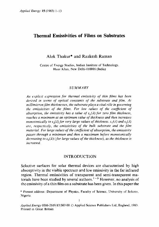
Consider an isotropic non-magnet ic thin film of uniform thickness, d, and refractive index [n2(2 ) - ik2()~)] on an isotropic non-magnet ic substrate of refractive index [n~ (2) - ik I ()0] (Fig. 1). Let e 1 (2) d)L be the radiative power per unit volume, between the wavelengths )t and 2 + d)., of the substrate. Thus, the total radiative energy emitted per unit area of the substrate and emerging from the upper surface of the film (z = 0) per unit time per unit solid angle is given 7 by:
I~(2) d2 = e l (2 )d2 T~3ex p [ -4 r&l (2 ) r /2 ] dr (1) = d s e c 0 2
The lower limit of the integral characterises the upper surface of the substrate and the net intensity transmission coefficient, T 13, is:
{ r/3 c°s 03 }×½[ITp312+,T~3, 2 ] (2) T,3 = R e [na(2) Z~; (~- ) ] cos O, 1 1
where n 3 is the refractive index of the vacuum, i.e. unity.
~ U VOcUum Fi lm
2(k)-ik2(k)]
bstrote
k)-ik1(k]]
z _ o o ~
Fig. 1. Schematic ray diagram.
Thermal emissivities of films on substrates 3
Angles 01, 0 2 and 03 appear ing in eqns (1) and (2) are related by expression (A(3)) given in the Appendix . Tpl 3 and Tsla are the ampl i tude t ransmission coefficients for parallel and perpendicular ly polarised radiat ions, respectively, and expressed 10 - 11 a s :
tml2tm23 exp( - ifl) Tin13 ~ 1 + r x z r 2 3 e x p ( - 2 i f l ) (3)
Suffix m stands for both p- and s -componen t s and:
27r fl = ~ - [n2(2 ) -- ik2()0] d c o s 0 2 (4)
A
It may be noted that eqn. (3) takes into account multiple reflections which radia t ions suffer while passing th rough the film: the t's and r's in eqn. (3) are Fresnel coefficients for t ransmission and reflection, respectively. Suffixes 1, 2 and 3 in these equat ions indicate various media. Fol lowing St ra t ton 1 o one can write the Fresnel coefficients for an absorbing m e d i u m as follows:
2[n1(2 ) - ik l (2)]cosO 1 tpl 2 = [rt2()t) _ ik2().)] co s 01 + [n1 (2 )_ ikl()t)]cosO 2 (5(a))
2[n1(2 ) - ik l (2) ]cos 01 ts12 = [nl()~ ) _ ik l (2 ) ]cos 01 + [n2(2) _ ik2(2)] cos 02 (5(b))
[n2(). ) -- ik2(),)] cos 01 - [n1(2 ) - ikl(2)] cos 0 2
FpI2 = [H2(). ) - - ik2(,~)] cos 01 --]-- [/ql (,/~) - ikl().)]cos 02 (5(c))
[nl ().) - iklO.)] cos 01 - [ n 2 ( ) ~ ) - ik2(•)] COS 0 2 (5(d))
r.~, 2 = [n~ ().) - ik1(2) ] cos 01 + [n2().) - ikz(2)] cos 02
Consider the emission of radiat ive energy within the film. Let ez(2 ) d2 be the radiative power per unit volume between wavelengths 2 and ), + d), of the film. Thus, following Ga r don , 7 one can write the direct ional radiative energy emit ted per unit area o f the surface (z = 0) per unit t ime per unit solid angle between wavelengths 2 and 2 + d2 in the following manner .
t dsec0
I2().)d). = e2().) d). T23ex p [-4~zkz().)r/) .]dr (6) Jr=O
where the in tegrand is the effective intensity t ransmission coefficient of the
4 Alok Thakur, Raakesh Raman
VQcuum
'
I d d /
/ / ~ c l l
S d.O.. 1 Subsirate [-n I¢x)- ik~(x)]
/ / / /
/ / ~// d_fL 2 2 t dv (2)
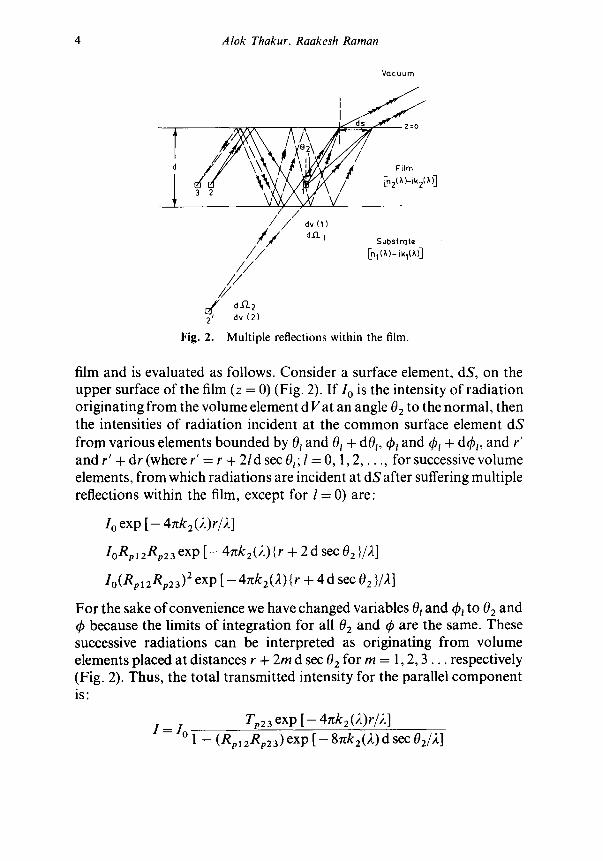
Fig. 2. Multiple reflections within the film.
film and is evaluated as follows. Consider a surface element, dS, on the upper surface of the film (z = 0) (Fig. 2). If I o is the intensity of radiat ion originating f rom the volume element d Vat an angle 02 to the normal , then the intensities of radiat ion incident at the c o m m o n surface element dS f rom various elements bounded by 0~ and 01 + d01, thl and 4~t + dth~, and r' and r' + dr (where r' = r + 2 /d sec 0t; l = 0, 1 , 2 , . . . , for successive volume elements, f rom which radiat ions are incident at dS after suffering multiple reflections within the film, except for l = 0) are:
I o exp [ - 4 n k 2 ( 2 ) r / 2 ]
IoRp 12Rp23 exp [ -- 4~zk 2 (2) { r + 2 d see 02 }/2]
Io(RplzRp23) 2 exp [ - 4 x k z ( 2 ) { r + 4 d sec 0 2 }/2]
For the sake of convenience we have changed variables 0t and th~ to 02 and th because the limits of integrat ion for all 02 and q~ are the same. These successive radiat ions can be interpreted as originating f rom volume elements placed at distances r + 2m d see 02 for m = 1,2, 3 . . . respectively (Fig. 2). Thus, the total t ransmit ted intensity for the parallel componen t is:
Tp23 exp [-- 4 x k 2 ( 2 ) r / 2 ]
I = I o 1 - ( R p 1 2 R p 2 3 ) exp [ - 8~zk2(2 ) d see 02/2 ]
Thermal emissivities of films on substrates 5
Therefore the intensity transmission coefficient of the parallel componen t is:
I Tp2 3 exp [ - 47tk2(2)r/2 ] T' __ (7(a)) "p23 = Io = 1 -Rp12Rp23exp[-8rtkz(2)dsec02/2 ]
Similarly, for the S componen t :
Ts23 exp [ - 4~zk2(2 ) • r/2] T~23 = 1 - RslzRs23 exp [ - 8rtk2(2 ) • d sec 02/2 ] (7(b))
The intensity transmission coefficient for completely unpolarised radi- at ion in an absorbing med ium is:
T23 1 r = 3(Tp23 + T~23)/exp ( - 4rtk 2 (2)r/2) (8)
Tra23 and Rm23 (for m = p or s) in eqn. (7) may be expressed as:
n3(2)COS 03 "~ Tin23 = R e [ [ n 2 ( ~ k ~ - c o s 0 2 . ~ × It,n2312 (9)
Rm23 = frm2312 (10)
In eqns (2) and (9), Re represents the real part of the argument . Using eqns (1) and (6), the total radiative energy emitted per unit area
between wavelengths 2 and 2 + d 2 by the film and the associated substrate is:
I(2) d2 = e~ (2) d2 T~ 3 exp [ - 4r~k~ (2)r/21 dr = d s e c 0 2
or:
I d s e c O
+ e2(2 ) d2 T23 exp [ - 4rck2(2)r/2 ] dr dr=O
1(2) d2 - 2el (2) d2 4xk a (2)
T13 exp [ - 4nk 1 (2) d sec 82/2 ]
+ 2e2(2)d2
4rtk2(2) Ta3[1 - exp { - 4nk2(2 ) d sec 02/2}] (11)
But e(A)/k(2) is constant for all substances (Kirchhoff 's law). Thus:
e1(2) _ e2(2 ) e(2) - - = . , .
k2(2) k(2)
6 Alok Thakur, Raakesh Raman
With this, eqn. (11) reduces to:
2e(2) 1(2) d2 - 4~zk(2~ [Tx 3 exp { - 4~k I (2) d sec 02/2 }
+ T23 { 1 - exp ( - 4~k 2 (2) d sec 02/2 ) }] (12)
Equat ion (12) represents the total directional radiation emitted by a film of thickness, d, formed over a semi-infinite substrate. Terms within square brackets may be interpreted as the effective transmission coefficient of the system (film and substrate).
For a black body the transmissivity is unity. Thus, black body radiations can be expressed as:
/black(/],) d2 - 2e(2) d2 (13) 4~k(2)
where e(2) and k(2) are the volume emissive power and extinction coefficient of the black body, respectively.
The directional emissivity can be expressed as the ratio of a real body radiat ion to the black body radiation. Thus:
1(2) d2 8o --/black(),) d2 - TI 3 exp [ - 4nk i (2) d sec 02/2 ]
+ T23[1 - e x p { - 4 g k 2 ( ) O d s e c O 2 / ) ~ } ] (14)
We should ment ion here that the a rgument that the angular spectral emissivity of a thick sample is equivalent to the t ransmit tance of the thick sample for emitted radiations, or (1 - R ) where R is the reflectance of vacuum radiations at the surface of the thick sample, 14 is not valid for thin films. This is because of the incoherence of the emitted thin film radiations, 15 which is due to the different sources for each radiation (Fig. 2). Vacuum radiation suffering multiple reflections within the film exhibits coherence between successively reflected rays, as merely a division of ampli tude occurs. 13
The hemispherical spectral emissivity of a thin film over a substrate can be found out by integrating eqn. (14) over a hemisphere, namely:
I n~2
~(2) = 2 t o sin 0 3 cos 0 3 d0 3 (15) dO
Equat ion (15) is the appropr ia te expression for spectral emissivity of thin films of complex refractive index [nz(2 ) - ik2(2)] over an absorbing substrate..
Thermal emissivities of films on substrates 7
It may be of interest to note that as the thickness d ~ 0 , eqn. (15) gives the emissivity e~()0 of the substrate and for d ~ ~ eqn. (15) represents emissivity e2(2) of the film material.
NUMERICAL RESULTS AND DISCUSSION
To obtain a numerical appreciation of the analysis we have chosen some arbitrary values of refractive index and extinction coefficients for the film as well as the substrate. Calculations were carried out on an ICL-2960 computer.
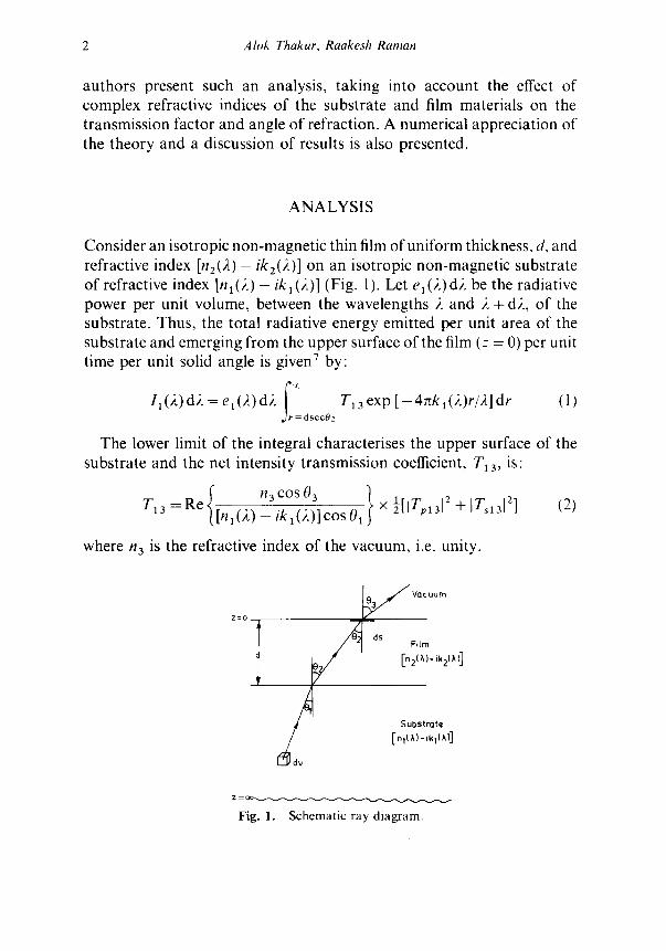
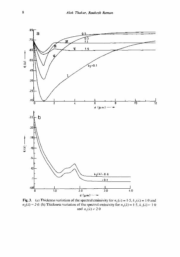
Figure 3(a) illustrates the dependence of the emissivity on the film thickness for various values of extinction coefficient k2()~ ) of the film. At d = 0 all the curves meet at a point: this is expected since, as d-~0, the emissivity approaches that of the substrate. Thus, at d = 0, the emissivity corresponds to that of the substrate only. It may be seen that the thermal emissivity of a thin film depends on the optical constants of the film material (Figs 3(a) and (b)). For low values of the extinction coefficient, the emissivity has a value e1(2 ) for zero thickness of the film, reaches a minimum at an opt imum film thickness and then increases monotonically to e2(2) for very large values of film thickness (see curves I, II and III of Fig. 3(a)). The initial decrease in emissivity with increasing thickness is due to the strong absorption suffered by the substrate radiation by the film, only a small amount of radiation emerging, the net effect being a decrease in the emissivity. As the thickness increases further, the emiss- ivity, after attaining a minimum, starts increasing and approaches ~2()0. This is due to the increase in the film emission which outweighs the decrease in emissivity due to increased attenuation of the substrate radiations by the film, and this results in a net increase in the emissivity.
Curves IV and V of Fig. 3(a)) (together with Figure 3(b) for different optical constants) illustrate that, for large values of k2(2), the emissivity passes through a minimum and then a maximum before monotonically decreasing to ez(2) (for large values of thickness), as the thickness is increased. This typical behaviour may be explained as follows. At small thicknesses, the film emission is lower than the substrate emission and, moreover, the film offers attenuation to the substrate radiation and thus a decrease in emissivity is observed up to some opt imum thickness. As the thickness increases further, the emissivity increases due to the increase in film emission, which outweighs the attenuation offered to the substrate
8 Alok Thakur, Raakesh Raman
t
• 95 -
.75 _a o~
• 6 5 "E
.55
.15 ~ I ~ I ~ I , l , 0 2 4 6 8
d (~Um}- "-
f
I , I 10 12
,,j,,x
.22
.20
.18
.1G
.1/,
-12
.1
.08
b
k2(k )=8 .6
=9.1
J I I I 0 1.0 2.0 3.0 i..0
d (/am)- -
Fig. 3. (a) Th i cknes s v a r i a t i o n o f the spec t ra l emiss iv i ty for n, (2) = 1.5, k 1 (2) = 1-0 a n d n2(2) = 2.0. (b) T h i c k n e s s v a r i a t i o n o f the spec t ra l emiss iv i ty for n 1 (2) -= 1.5, k I (2) = 1.0
a n d n2(2 ) -- 2.0.
Thermal emissivities of films on substrates 9
.8
.6
.5
./4
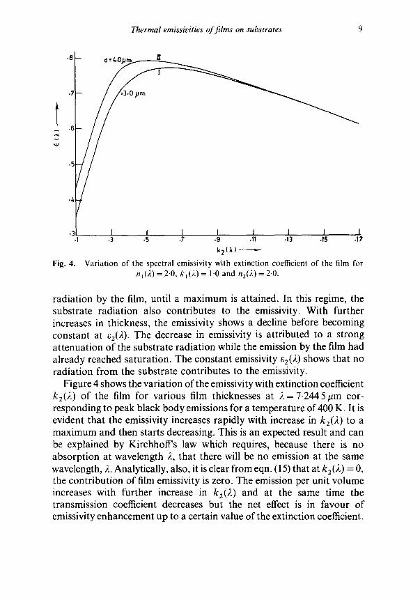
Fig. 4.
I I I I I I I I • 3 .5 .7 -9 .1! .13 .15 .17
k2(~)
Variation of the spectral emissivity with extinction coetiicient of the film for hi(2 ) =2-0, kt(2 ) = 1.0 and n2(2)=2.0 .
radiation by the film, until a maximum is attained. In this regime, the substrate radiation also contributes to the emissivity. With further increases in thickness, the emissivity shows a decline before becoming constant at e2(2 ). The decrease in emissivity is attributed to a strong attenuation of the substrate radiation while the emission by the film had already reached saturation. The constant emissivity e2(2) shows that no radiation from the substrate contributes to the emissivity.
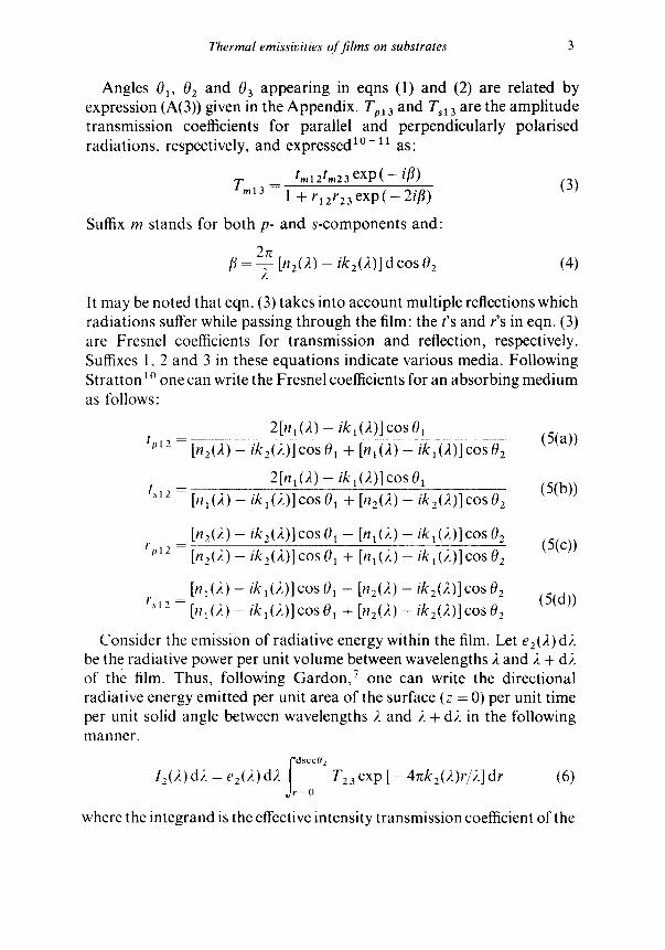
Figure 4 shows the variation of the emissivity with extinction coefficient k2(2) of the film for various film thicknesses at 2 = 7.2445#m cor- responding to peak black body emissions for a temperature of 400 K. It is evident that the emissivity increases rapidly with increase in k2(2 ) to a maximum and then starts decreasing. This is an expected result and can be explained by KirchholTs law which requires, because there is no absorption at wavelength 2, that there will be no emission at the same wavelength, 2. Analytically, also, it is clear from eqn. (15) that at k 2 (2) = 0, the contribution of film emissivity is zero. The emission per unit volume increases with further increase in k2(2 ) and at the same time the transmission coefficient decreases but the net effect is in favour of emissivity enhancement up to a certain value of the extinction coefficient.
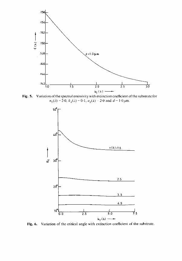
Fig. 5.
t ..<
~ J
Fig. 6.
-156 -
-I 5~
.152
.150 -
.I/,8
.I/,G
.IM, ~
1.0 1.5 2.0 2.5 3.o
k I (~,) Variation of the spectral emissivity with extinction coefficient of the substrate for
n1(2) = 2.0, k2()~) = 0.1, n2(2 ) = 2.0 and d = I.Oym.
t
5o ~
2o ~
n(A):1.5
2.5
3.5
/..5
I I I 0.0 2.5 5.0 7.5
k I (,~} ,-
Variation of the critical angle with extinction coefficient of the substrate.
Thermal emissivities o f films on substrates 11
A further increase in k(2) increases the emission per unit volume but the magnitude of the corresponding decrease in the transmission coefficient is more significant than the former and hence this results in a net decrease in the emissivity.
The variation of the spectral emissivity with extinction coefficient of the substrate is shown in Fig. 5 at d = 1.0 pm and 2 = 7.244 5 #m. It is evident from the curves that the spectral emissivity shows a monotonic decrease with extinction coefficient. This may be explained on the basis of a decrease of critical angle of incidence with increasing k1(2 ) (Fig. 6). A similar behaviour for emissivity can be seen with the refractive index of the substrate.
CONCLUSIONS
The emissivity of a thin film depends strongly upon the optical characteristics of the substrate. However, the thin film also plays a vital r61e in controlling the emissivity of the substrate. It is envisaged that this work will be useful for solving future solar energy instrumentation problems.
A C K N O W L E D G E M E N T
The authors are grateful to Professor M. S. Sodha, Deputy Director, liT, New Delhi, India, for many stimulating discussions.
APPENDIX A: EVALUATION OF THE ANGLE OF REFRACTION
Consider a thin film of complex refractive index [n2(). ) --ik2(),)] on a semi-infinite substrate of refractive index [n~(2)-ik~().)] at a finite temperature T(K). The other boundary of the film is assumed to face a vacuum (Fig. 1). At this temperature T(K), the film, as well as the substrate, will emit radiations whose frequencies are governed by Planck's law. 12 Let an electromagnetic wave of angular frequency, ~o, originate in the substrate and propagate through the film before emerging out into the vacuum: 0~, 02 and 03 are the angle of incidence at the substrate boundary, the angle of refraction in the film and the angle of
12 A lok Thakur, Raakesh Raman
[ 03 Vacuum
z:o Plane of ~
I\ J . . . . . ~ Plane of constant amplitude
z : d n ~ / ~ ' s / ~ t a n t ~ / ~ j Plane of co Substrote phase an d constant ~ . ! ["n,(•]-ik (A)-J
ampl,tude / "~ L"I . . . . . 1 .J I
Z=OO
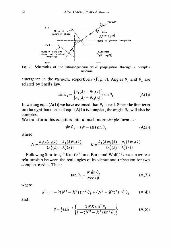
Fig. 7. Schematics of the inhomogeneous wave propagation through a complex medium.
emergence in the vacuum, respectively (Fig. 7). Angles 01 and 02 are related by Snell's law.
= ~ n1(2) - ik'()0 } sin 01 (A(I)) sinO2 [nz~ ~ ikz(2.)
In writing eqn. (A(1)) we have assumed that 01 is real. Since the first term on the right-hand side ofeqn. (A(1)) is complex, the angle, 02, will also be complex. We transform this equation into a much more simple form as:
sin 02 = ( N - i K ) sin 01 (A(2))
where:
N = nl(2)n2(2) + kl(2)k2(2) K = kl(2)n2(2) - nl (2)k2(2) {n2(2) + k2Z(2) } {n2Z(~) + kzZ(2) }
Following Stratton, ~ 0 Knittle 11 and Born and Wolf, 13 one can write a relationship between the real angles of incidence and refraction for two complex media. Thus:
Nsin01 tan 0 2 (A(3))
COS f l
where:
and:
o~ 4 = 1 - 2 ( N 2 - K 2) sin 2 01 + (N 2 + K2) 2 sin 4 01 (A(4))
2NKsin 2 01 } (A(5)) /3=½tan-1 1 - ( N 2 - K 2)sin z01
Thermal emissivities of films on substrates 13
It may be seen that eqn. (A(3)) readily reduces to Snell's law (n1(2) sin 01 = n2(2) sin 02) for a completely non-absorbing medium. Thus, eqn. (A(3)) may be referred to as the generalised Snell's law.
R E F E R E N C E S
1. H. O. McMahon, J. Opt. Soc. Am., 40(1950), pp. 37(~80. 2. H. O. McMahon, J. Am. Ceram. Soc., 34(3) (1951), pp. 91-6. 3. B. S. Kellet, J. Opt. Soc. Am., 42(5), (1952), pp. 339-43. 4. B. S. Kellet, J. Soc. Glass Technol, 36(169) (1952), pp. 115-23. 5. M. Czerny and L. Genzel, Glastech. Ber., 25(5) (1952), pp. 134-9. 6. B. S. Kellet, J. Soc. Glass Technol., 37(178) (1953), pp. 268. 7. R. Gardon, J. Am. Ceram. Soc., 39 (1956), pp. 278-87. 8. P. Drude, Lehrbuchder Optik, (1912), 5 Hirzel, Leipzig. 9. L. Geffcken, Glastech. Ber., 25(12) (1952), pp. 392-6.
10. J. A. Stratton, Electromagnetic theory, McGraw Hill Book Co. Inc., NY, 1941.
11. Z. Knittle, Optics of thin films, John Wiley and Sons, London, 1976. 12. J.A. Duffle and D. A. Beckman, Solar energy thermalprocesses, John Wiley
and Sons, NY, 1980. 13. M. Born and E. Wolf, Principles of optics, Pergamon Press, Oxford, 1975. 14. R. Raman and A. Thakur, Applied Energy, 12 (1982), pp. 205-20. 15. G. Wass (Ed.). Physics of thin films, Vol. 2, Academic Press, 1964.


![Thermal annealing of sequentially deposited SnS thin films...Deposition of ZnS films The ZnS thin films were prepared by a CBD technique described elsewhere [17]. Corning glass substrates,](https://img.pdfslide.us/doc/110x75/60f8714f107e0617217e0a24/thermal-annealing-of-sequentially-deposited-sns-thin-films-deposition-of-zns.jpg)