Embed Size (px)
Citation preview

Nuclear Instruments and Methods in Physics Research A266 (1988) 513-516 513 North-Holland, Amsterdam
T H E R M A L D E F O R M A T I O N S IN A H I G H F L U X B E A M P O S I T I O N M O N I T O R
S. S H A R M A and M. W O O D L E
National Synchrotron Light Source, Brookhaven National Laboratory, Upton, New York 11973, USA
Beam position monitors in three of the X-ray beam lines at the National Synchrotron Light Source employ a pair of metal blades at predetermined gaps. The thin blades intercept the fringes of the photon beam and generate an electrical signal which determines the relative beam position. The beam power deposited on the blades is removed by heat pipes to a heat exchanger outside the vacuum vessel. In this paper, we present results from nonlinear finite element analyses to describe temperature and deformation fields in a position monitor blade subassembly designed for a high flux soft X-ray beam line. These analyses show that, for the worst case of beam exposure, one of the blades would be subjected to high temperature gradients. The resulting thermal stresses can then exceed the temperature-dependent yield stress of the blade material, causing substantial plastic deformations. We compare the analysis results for two different blade materials, namely, tungsten, and a molybdenum alloy (TZM).
1. Introduction
Insertion devices are presently being installed in three of the X-ray beam lines at the National Synchro- tron Light Source (NSLS). Specifically, final assembly is in progress for a hybrid undulator, a superconducting wiggler, and a hybrid wiggler for the beam lines X-l, X-17, and X-25, respectively.
Experimental stations in these beam lines are com- paratively long distances (typically 15-20 m) away from the sources. Consequently, even small angular devia- tions of the beam would result in large beam displace- ments at the experimental locations. Beam position monitors are therefore used to detect the beam devia- tions [1]. The thin pair of metallic blades of the position monitors generate small electrical currents when the blades are projected into the fringes of the photon beam. This current is used as a feedback signal to the storage ring trim magnets which make proper adjust- ments to the electron beam orbit to correct the photon beam deviations. One position monitor is used in each of the three beam lines for vertical monitoring of the beam. An additional position monitor is installed in the X-1 beam line to monitor the beam horizontally because of the comparatively small horizontal size of the undu- lator beam.
The position monitor blades are exposed to substan- tial amounts of heat from the incident high power photon beam. Each blade is cooled by a heat pipe which removes the heat to a heat exchanger outside the vacuum chamber. The heat transfer through the blades causes severe temperature gradients which can result in high thermal stresses. In this paper we present analysis re- suits for the horizontal beam position monitor of the X-1 beam line. This particular position molaitor is con-
0168-9002/88/$03.50 © Elsevier Science Publishers B.V. (North-Holland Physics Publishing Division)
sidered because it can intercept more photon power than either of the three vertical position monitors [1].
2. Thermal problem
Designed primarily for soft X-ray imaging, the hy- brid undulator of the X-1 beam line at NSLS consists of 37 periods of 80 mm period length. The device has an extremely high photon flux contained in a small beam size. The photon flux and power can be approximated by Gaussian distributions with horizontal and vertical standard deviations of 0.24 and 0.05 mrad, respectively, for the maximum K parameter value of 2.6 [2]. Peak power density for this K value is 2.3 kW/mrad 2 corre- sponding to a maximum current of 500 mA in the 2.5 GeV storage ring. The horizontal and vertical power distributions from the undulator are depicted in fig. 1.
A typical beam position monitor assembly is shown in fig. 2. As shown, a pair of thin (0.254 mm) metallic blades are used which in normal operation intercept only the outer fringes of the photon beam. The 57 mm long and 25 mm wide blades are tapered on the edge facing the beam in order to spread the heat load by reducing the angle of incidence. Originally, the blade material was to be tungsten, however, because of exces- sive thermal stresses as discussed in this paper, an alloy of molybdenum (TZM) was eventually selected. Each blade is furnace brazed to a thick copper base plate which is mechanically connected to the evaporator end of the heat pipe. The condenser end of the heat pipe is cooled by a small water heat exchanger. A beryllia sleeve is used between the heat pipe and the cooling water in order to electrically isolate the monitor blade subassembly.
Ill(f). THERMAL CONSIDERATIONS

514 S. Sharma, M. Woodle / Thermal deformations
q
to
c~
c~ o
0 . 0 0
LEGEND
HORIZONTAL
VERTICAL
[ 'l ........... F . . . . . . T ....
0.25 0.50 0.75 1.00
ANGLE (mrad) 1.125 1 .i5
Fig. 1. Power distributions from the X-1 hybrid undulator vs total subtended angle.
The horizontal position monitor is installed at 9.2 m from the source. At this distance one of the blades can accidentally intercept the entire horizontal width of the beam at its peak power density. The total power de- posited on the blade is then given by the integral of the
horizontal power distribution multiplied by the blade thickness. For the present case the calculation yields a heat load of 55.2 W. This heat input can be easily removed by the heat pipe without exceeding a tempera- ture of approximately 65 ° C at the contact interface of the copper base plate [3]. The interface temperature of 65 ° C is used as the boundary condition in the analysis models describe in the following section.
3. Analysis models and results
A finite element computer orogram, ANSYS [4], was used for the heat transfer and thermal stress analyses of the position monitor. Although heat transfer in the blade-base plate subassembly is spatially three dimen- sional, a full 3-D finite element model of the subassem- bly would be excessively complex. A combination of 2-D and partial 3-D models was, therefore, used as a compromise. The same 3-D element geometry was sub- sequently employed for the nonlinear thermal stress analysis. The two finite element models are shown in fig. 3. The 2-D thermal model of ANSYS permits only a unit transverse thickness. This limitation was cir- cumvented by representing the varying thickness of the actual subassembly by a proportionate change in the thermal conductivity of the materials. Nominal thermal conductivity values for copper, tungsten and TZM were taken to be 3.86, 1.67 and 1.46 W/(cm o C), respectively
Base Plate Feed Through
Fig. 2. X-1 horizontal beam position monitor.

A
A
b
R
S. Sharma, M. Woodle / Thermal deformations 515
A
Fig. 3. Finite dement models of the blade-base plate subas- sembly, (a) 2-D finite element model; (b) 3-D finite element
model.
[5]. In both the models, the heat load was applied at the worst location, i.e., at the lower corner of the tapered edge.
Temperatures obtained at Section A-A (fig. 3a) of the 2-D model were used at corresponding nodes of the base plate in the partial 3-D model. Analysis results for the nodal temperatures are plotted as temperature con- tours in figs. 4a and 4b, respectively, for the tungsten and TZM blades. The temperature distributions ob- tained by the 3-D model are in reasonably good agree- ment with those predicted by the approximate 2-D model. The figure shows that high temperatures are obtained in the blade region which intercepts the beam. They drop rapidly in regions approaching the base plate, thus resulting in severe temperature gradients. Temperatures in most of the base plate are below 100°C. As expected, the maximum temperature of 1050 °C in the molybdenum TZM blade is higher than that in the tungsten blade (950 ° C) because of the lower thermal conductivity of the TZM alloy.
Temperature distributions from the heat transfer analysis were provided as input to the thermal stress models. Required material properties were taken from refs. [5,6]. The values used for the thermal coefficient of expansion for tungsten and TZM are 4.5 x 10 -6 and 5.2 X ] 0 - 6 cm/(cm ° C), respectively. The elastic mod- uli and yield strengths of these materials were consid- ered to be temperature dependent since they decrease significantly at high temperatures. Table 1 lists their
a
Copper Base Plate
I 1 I I
TEMPERATURE (deg C)
A~IS0
B~SO C~350
D~450 E~559
F~650
G~750 H -850
I=950
Fig. 4. Temperature contours in the position momtor (a) Tungsten blade; (b) TZM blade.
TEMPERATURE (deg 0 A-15O B--250 C~350 ]3=-45O E~550 P~650 G~750 H~850 I=950 J=105O
blades.
values in psi (1 psi = 6.895 x 10³ Pa) at various temper- atures.
Thermal deformations for both the tungsten and TZM blades are shown in fig. 5. For clarity, the defor- mations are magnified by a factor of 25, and only the blade edges are shown together with the original finite element geometry. The tungsten blade, which has a lower temperature rise (fig. 4) as well as a lower thermal coefficient of expansion, is subjected to smaller thermal deformations than the TZM blade. For instance, maxi- mum displacements at the lower left comer of the tungsten and TZM blades are 0.08 mm and 0.11 mm, respectively. Thermal deformations in either case are, however, too small to cause any significant change in the blade's spatial or angular position with respect to
Table 1 Temperature-dependent elastic moduli and yield strengths.
Materials Temperature Elastic Yield ( ° C) modulus strength
(×106 psi) (×103 psi)
Tungsten 22 59 220 204 58 40 871 55 15
1000 40 14
Molybdenum 22 46 115 TZM 871 34 55
1316 21 40
Ill(f). THERMAL CONSIDERATIONS
516 S. Sharma, M. Woodle / Thermal deformations
~ , : : S -'~
TUNGSTEN BLADE
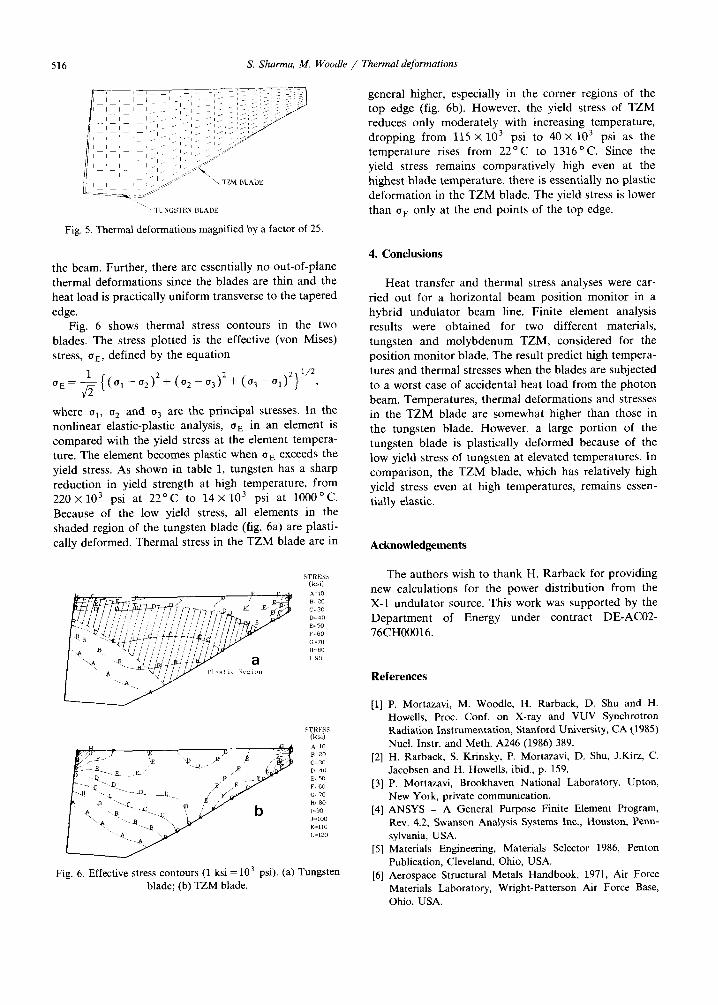
Fig. 5. Thermal deformations magnified by a factor of 25.
the beam. Further, there are essentially no out-of-plane thermal deformations since the blades are thin and the heat load is practically uniform transverse to the tapered
edge. Fig. 6 shows thermal stress contours in the two
blades. The stress plotted is the effective (von Mises) stress, o E, defined by the equation
1 - ° 2 ) 2 ~ - { ( O 1 q- ( 0 2 -- 0 "3 ) 2+ ( 0 3 - - O 1 ) 2 } 1/2
where o 1, 02 and 03 are the principal stresses. In the nonlinear elastic-plastic analysis, 0 E in an element is compared with the yield stress at the element tempera- ture. The element becomes plastic when 0 E exceeds the yield stress. As shown in table 1, tungsten has a sharp reduction in yield strength at high temperature, from 220×103 psi at 2 2 ° C to 1 4 × 1 0 3 psi at 1000°C. Because of the low yield stress, all elements in the shaded region of the tungsten blade (fig. 6a) are plasti- cally deformed. Thermal stress in the T Z M blade are in
general higher, especially in the corner regions of the top edge (fig. 6b). However, the yield stress of T Z M reduces only moderately with increasing temperature, dropping from 115 x 103 psi to 40 x 103 psi as the temperature rises from 2 2 ° C to 1316°C. Since the yield stress remains comparatively high even at the highest blade temperature, there is essentially no plastic deformation in the T Z M blade. The yield stress is lower than o E only at the end points of the top edge.
4. Conclusions
Heat transfer and thermal stress analyses were car- fled out for a horizontal beam position monitor in a hybrid undulator beam line. Finite element analysis results were obtained for two different materials, tungsten and molybdenum TZM, considered for the position monitor blade. The result predict high tempera- tures and thermal stresses when the blades are subjected to a worst case of accidental heat load from the photon beam. Temperatures, thermal deformations and stresses in the T Z M blade are somewhat higher than those in the tungsten blade. However, a large portion of the tungsten blade is plastically deformed because of the low yield stress of tungsten at elevated temperatures. In comparison, the T Z M blade, which has relatively high yield stress even at high temperatures, remains essen- tially elastic.
Acknowledgements
STRES~ (ks,)
STRESS (k~i)
;4 _ ~. ~- A =I0
F=60
L~I20
Fig. 6. Effective stress contours (1 ksi = 1 0 3 psi). (a) Tungsten blade; (b) TZM blade.
The authors wish to thank H. Rarback for providing new calculations for the power distribution from the X-1 undulator source. This work was supported by the Department of Energy under contract DE-AC02- 76CH00016.
References
[1] P. Mortazavi, M. Woodle, H. Rarback, D. Shu and H. Howells, Proc. Conf. on X-ray and VUV Synchrotron Radiation Instrumentation, Stanford University, CA (1985) Nucl. Instr. and Meth. A246 (1986) 389.
[2] H. Rarback, S. Krinsky, P. Mortazavi, D. Shu, J.Kirz, C. Jacobsen and H. Howells, ibid., p. 159.
[3] P. Mortazavi, Brookhaven National Laboratory, Upton, New York, private communication.
[4] ANSYS - A General Purpose Finite Element Program, Rev. 4.2, Swanson Analysis Systems Inc., Houston, Penn- sylvania, USA.
[5] Materials Engineering, Materials Selector 1986, Penton Publication, Cleveland, Ohio, USA.
[6] Aerospace Structural Metals Handbook, 1971, Air Force Materials Laboratory, Wright-Patterson Air Force Base, Ohio, USA.