Embed Size (px)
Citation preview
1
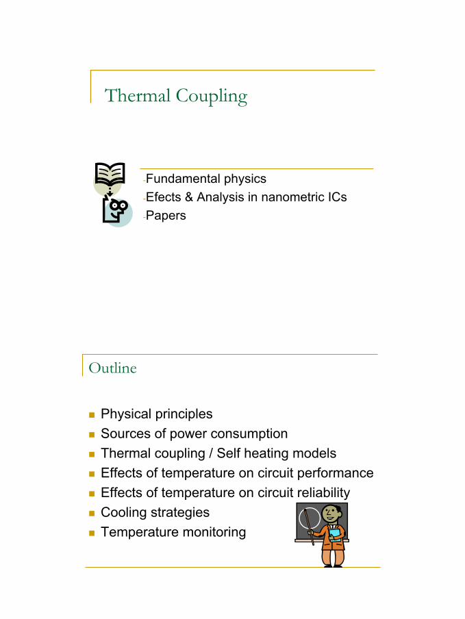
Thermal Coupling
-Fundamental physics-Efects & Analysis in nanometric ICs-Papers
Outline
Physical principlesSources of power consumptionThermal coupling / Self heating modelsEffects of temperature on circuit performanceEffects of temperature on circuit reliabilityCooling strategiesTemperature monitoring
2
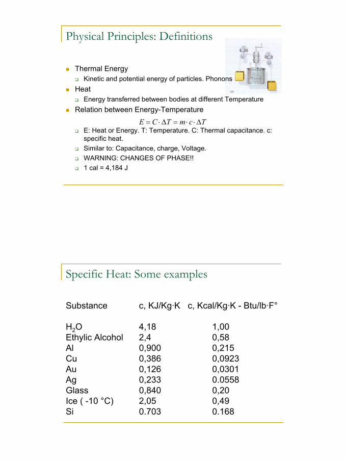
Physical Principles: Definitions
Thermal EnergyKinetic and potential energy of particles. Phonons
HeatEnergy transferred between bodies at different Temperature
Relation between Energy-Temperature
E: Heat or Energy. T: Temperature. C: Thermal capacitance. c: specific heat.Similar to: Capacitance, charge, Voltage.WARNING: CHANGES OF PHASE!!1 cal = 4,184 J
TcmTCE ∆⋅⋅=∆⋅=
Specific Heat: Some examples
Substance c, KJ/Kg·K c, Kcal/Kg·K - Btu/lb·F°
H2O 4,18 1,00Ethylic Alcohol 2,4 0,58Al 0,900 0,215Cu 0,386 0,0923Au 0,126 0,0301Ag 0,233 0.0558Glass 0,840 0,20Ice ( -10 °C) 2,05 0,49Si 0.703 0.168
3
Heat flow – Power – Heat transfer
Energy ratesJ/s = WTemporal Evolution of Temperature (Adiabatic condition)
Examples of heat generation:Joule EffectScattering of carriers in the conductor lattice and phonons
Temporal evolution of temperature (non adiabatic):Conservation of Energy
Stored energy (∆T) = Generated Energy – transferred energy
dtdTCtQtP
dtdE
⋅=== )()(
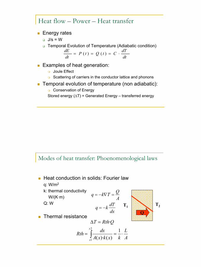
Modes of heat transfer: Phoenomenological laws
Heat conduction in solids: Fourier lawq: W/m2
k: thermal conductivityW/(K·m)
Q: W
Thermal resistancedxdTkq
AQTkq
−=
=∇−=
T1 T2
Q
AL
kxkxAdxRth
QRthTx
x
⋅==
=∆
∫1
)()·(
·2
1
4
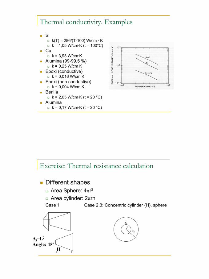
Thermal conductivity. Examples
Sik(T) = 286/(T-100) W/cm · Kk = 1,05 W/cm·K (t = 100°C)
Cuk = 3,93 W/cm·K
Alumina (99-99,5 %)k = 0,25 W/cm·K
Epoxi (conductive)k = 0,016 W/cm·K
Epoxi (non conductive)k = 0,004 W/cm·K
Beriliak = 2,05 W/cm·K (t = 20 °C)
Aluminak = 0,17 W/cm·K (t = 20 °C)
Exercise: Thermal resistance calculation
Different shapesArea Sphere: 4πr2
Area cylinder: 2πrhCase 1 Case 2,3: Concentric cylinder (H), sphere
H
Ai=L2
Angle: 45º
r1
r2
5
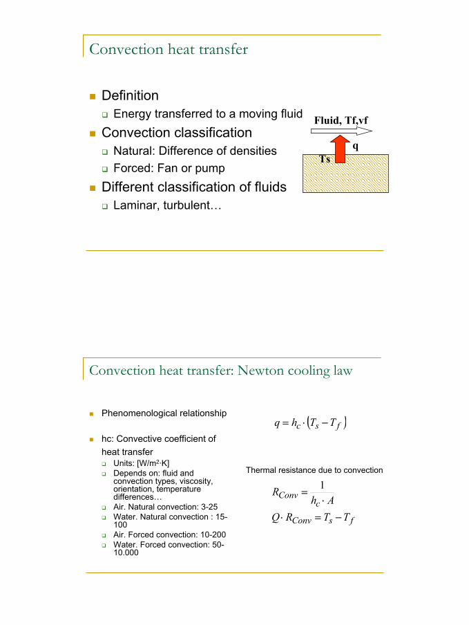
Convection heat transfer
DefinitionEnergy transferred to a moving fluid
Convection classificationNatural: Difference of densitiesForced: Fan or pump
Different classification of fluidsLaminar, turbulent…
Fluid, Tf,vf
qTs
Convection heat transfer: Newton cooling law
Phenomenological relationship
hc: Convective coefficient of heat transfer
Units: [W/m2·K]Depends on: fluid and convection types, viscosity, orientation, temperature differences…Air. Natural convection: 3-25Water. Natural convection : 15-100Air. Forced convection: 10-200Water. Forced convection: 50-10.000
( )fsc TThq −⋅=
fsConv
cConv
TTRQAh
R
−=⋅⋅
=1
Thermal resistance due to convection
6
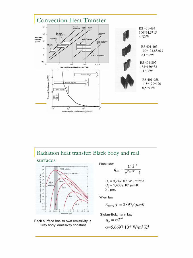
Convection Heat TransferRS 401-497100*64,5*154 °C/W
RS 401-403100*123,8*26,72,1 °C/W
RS 401-807152*130*321,1 °C/W
RS 401-958115*120*1200,5 °C/W
Radiation heat transfer: Black body and real surfaces
12
51
−=
−
TCb eCq λλλ
C1 = 3,742·108 W·µm4/m2
C2 = 1,4389·104 µm·Kλ : µm.
Plank law
mKTmax µλ 6,2897· =
Wien law
4Tqb σ=σ=5.6697·10-8 W/m2 K4
Stefan-Bolzmann law
Each surface has its own emissivity εGray body: emissivity constant
7
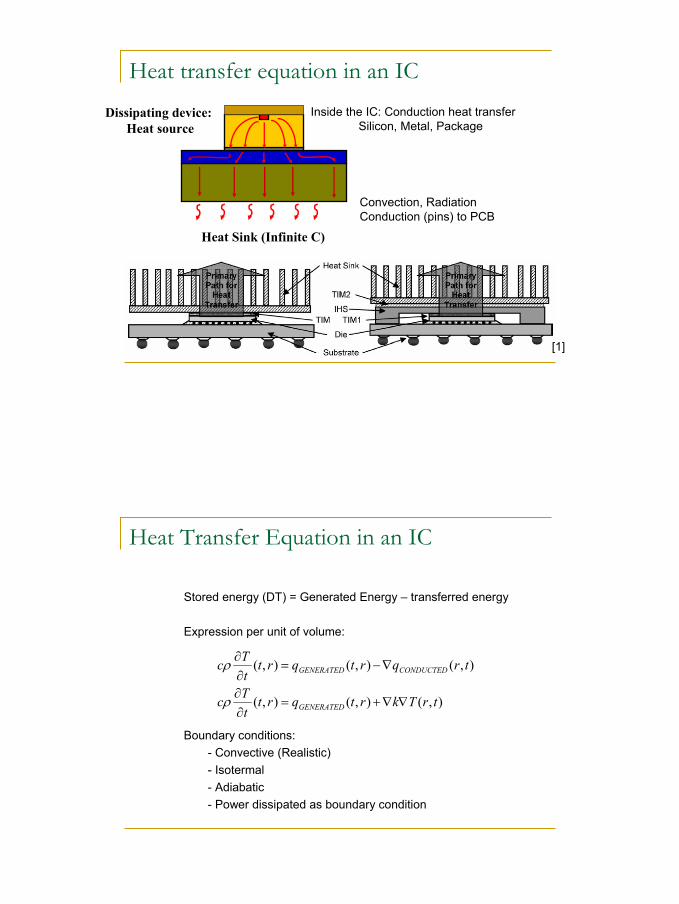
Heat transfer equation in an IC
Dissipating device:Heat source
Heat Sink (Infinite C)
Inside the IC: Conduction heat transferSilicon, Metal, Package
Convection, RadiationConduction (pins) to PCB
[1]
Heat Transfer Equation in an IC
Stored energy (DT) = Generated Energy – transferred energy
Expression per unit of volume:
Boundary conditions:- Convective (Realistic)- Isotermal- Adiabatic- Power dissipated as boundary condition
),(),(),(
),(),(),(
trTkrtqrttTc
trqrtqrttTc
GENERATED
CONDUCTEDGENERATED
∇∇+=∂∂
∇−=∂∂
ρ
ρ
8
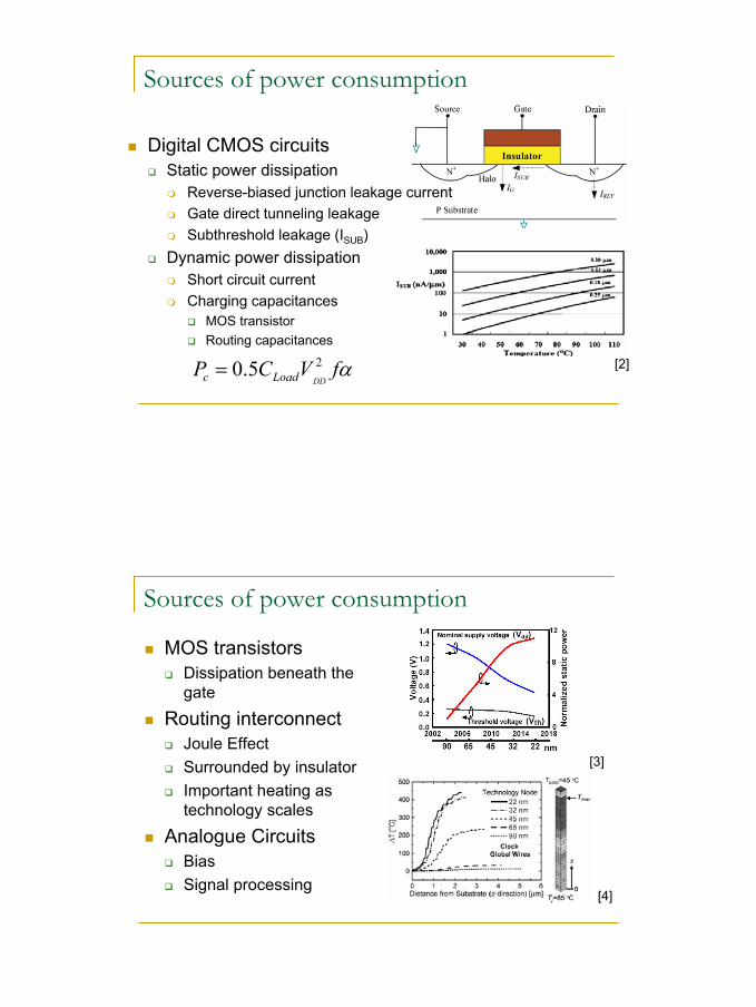
Sources of power consumption
Digital CMOS circuitsStatic power dissipation
Reverse-biased junction leakage currentGate direct tunneling leakageSubthreshold leakage (ISUB)
Dynamic power dissipationShort circuit currentCharging capacitances
MOS transistorRouting capacitances
[2]αfVCPDDLoadc25.0=
Sources of power consumption
MOS transistorsDissipation beneath the gate
Routing interconnectJoule EffectSurrounded by insulatorImportant heating as technology scales
Analogue CircuitsBiasSignal processing
[3]
[4]
9
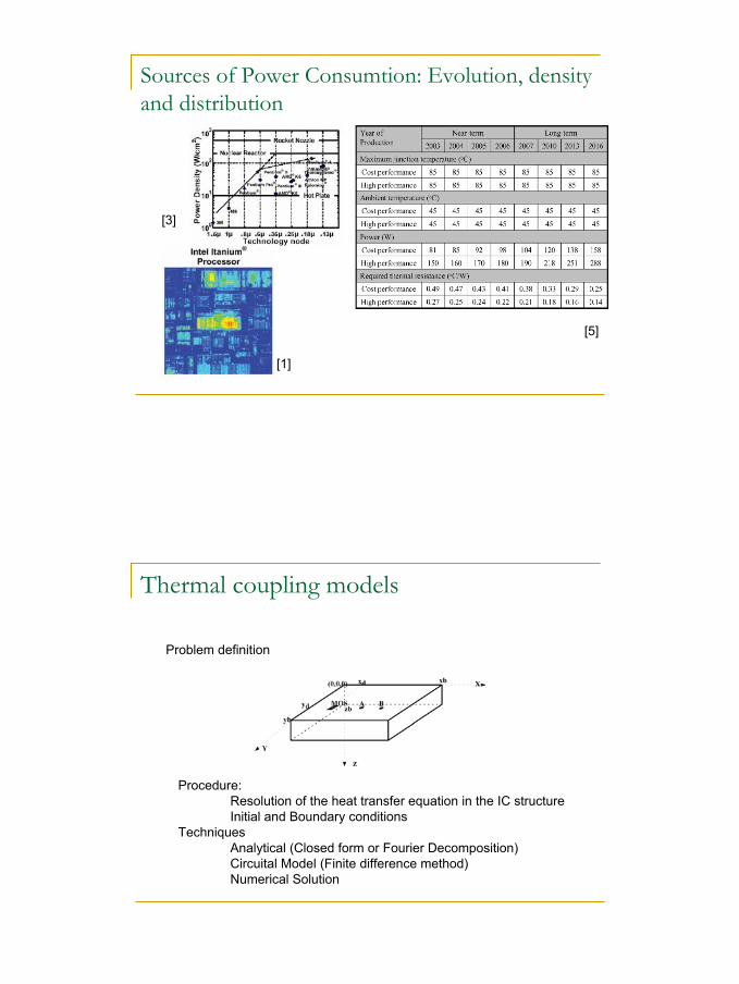
Sources of Power Consumtion: Evolution, density and distribution
[3]
[5]
[1]
Thermal coupling models
Problem definition
Procedure:Resolution of the heat transfer equation in the IC structureInitial and Boundary conditions
TechniquesAnalytical (Closed form or Fourier Decomposition)Circuital Model (Finite difference method)Numerical Solution
10
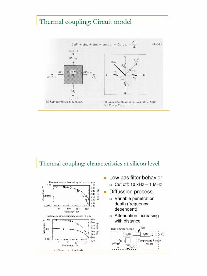
Thermal coupling: Circuit model
Thermal coupling: characteristics at silicon level
Low pas filter behaviorCut off: 10 kHz – 1 MHz
Diffussion processVariable penetration depth (frequency dependent)Attenuation increasing with distance
11
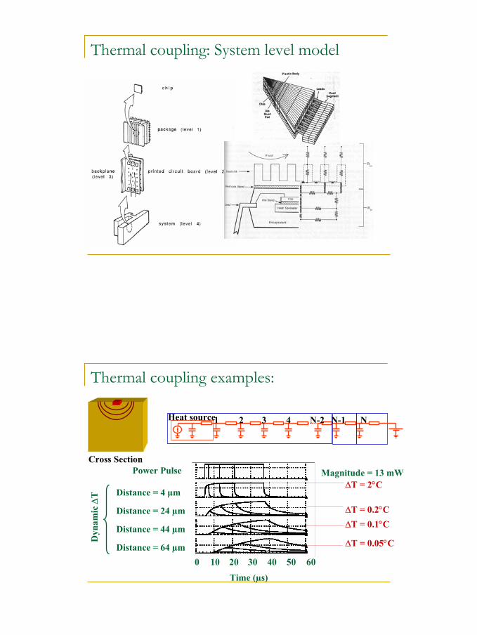
Thermal coupling: System level model
Thermal coupling examples:
Cross Section
Heat source1 2 3 4 N-2 N-1 N
Power Pulse
Dyn
amic
∆T Distance = 4 µm
Distance = 24 µm
Distance = 44 µm
Distance = 64 µm
∆T = 2°C
∆T = 0.2°C∆T = 0.1°C
∆T = 0.05°C
Magnitude = 13 mW
Time (µs)
0 10 20 30 40 50 60
12
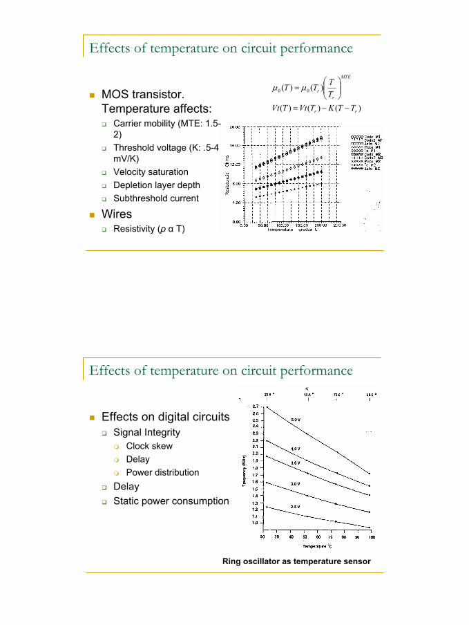
Effects of temperature on circuit performance
MOS transistor. Temperature affects:
Carrier mobility (MTE: 1.5-2)Threshold voltage (K: .5-4 mV/K)Velocity saturationDepletion layer depthSubthreshold current
WiresResistivity (ρ α T)
)()()(
)()( 00
rr
MTE
rr
TTKTVtTVtTTTT
−−=
= µµ
Effects of temperature on circuit performance
Effects on digital circuitsSignal Integrity
Clock skewDelayPower distribution
DelayStatic power consumption
Ring oscillator as temperature sensor
13
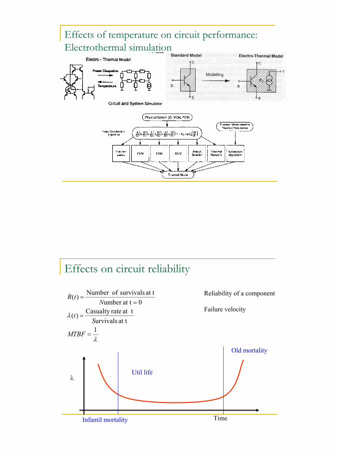
Effects of temperature on circuit performance: Electrothermal simulation
Effects on circuit reliability
λ
λ
1at t urvivals
at t rateCasualty )(
0at tumber at t survivals ofNumber )(
=
=
==
MTBF
St
NtR Reliability of a component
Failure velocity
λ
TimeInfantil mortality
Util life
Old mortality
14
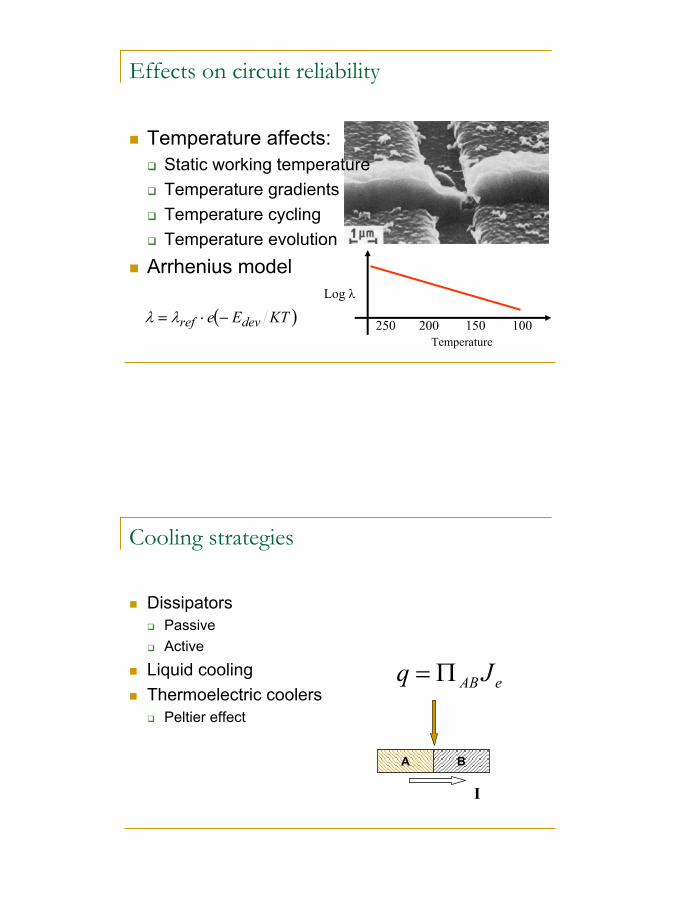
Effects on circuit reliability
Temperature affects:Static working temperatureTemperature gradientsTemperature cyclingTemperature evolution
Arrhenius model
( )KTEe devref −⋅= λλLog λ
250 200 150 100Temperature
Cooling strategies
DissipatorsPassiveActive
Liquid coolingThermoelectric coolers
Peltier effect
A B
I
eABJq Π=
15
Temperature monitoring
Built-in temperature sensorsAbsoluteDifferential
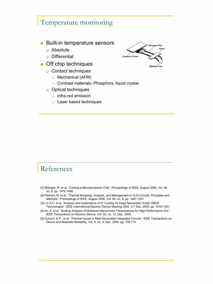
Off chip techniquesContact techniques
Mechanical (AFM)Contrast materials: Phosphors, liquid crystal
Optical techniquesInfra-red emissionLaser based techniques
References
[1] Mahajan, R. et al. “Cooling a Microprocessor Chip”, Proceedings of IEEE, August 2006, Vol. 94, no. 8, pp. 1476-1486
[2] Pedram, M. et al. “Thermal Modeling, Analysis, and Management in VLSI Circuits: Principles and Methods”, Proceedings of IEEE, August 2006, Vol. 94, no. 8, pp. 1487-1501
[3] Lin S.C. et al. “Analysis and Implications of IC Cooling for Deep Nanometer Scale CMOS Technologies”, IEEE International Electron Device Meeting 2005. 2-7 Dec. 2005. pp. 1018-1021.
[4] Im, S. et al. “Scaling Analysis of Multilevel Interconnect Temperatures for High-Performance ICs”, IEEE Transactions on Electron Device, Vol. 52, no. 12, Dec. 2005.
[5] Gurrum, S.P., et al. “Thermal Issues in Next-Generation Integrated Circuits”, IEEE Transactions on Device and Materials Reliability, Vol. 4, no. 4, Dec. 2004. pp. 709-714