Embed Size (px)
Citation preview
1 Thermal-Fluids Analysis Workshop, 2015
Thermal Control Architecture Trade Study for the Europa Clipper Pre-Project Study
Authors: Hared Ochoa, Pradeep Bhandari, A.J. Mastropietro, Anthony Paris Jet Propulsion Laboratory, California Institute of Technology, Pasadena, California, 91109
This paper details the technical trade study conducted for the Europa Clipper spacecraft concept
between active and passive thermal control architectures: specifically on the methodology, analysis, and
results used to determine the thermal subsystem power demands for both architectures. The trade
study results demonstrate the active thermal control architecture would be significantly more energy
efficient during the science observation phase of the mission. The Trade study also brought to light
some intricacies of the thermal architecture that will be further investigated in the future to improve the
design and performance of the baseline thermal subsystem. The Europa Clipper Pre-Project Study is a
mission concept under investigation in a partnership between the Jet Propulsion Laboratory and the
Applied Physics Laboratory.
Nomenclature AFT = Allowable Flight Temperature APL = Applied Physics Laboratory A.U. = Astronomical Unit BV = Bypass Valve CAD = Computer Automated Design CBE = Current Best Estimate CFC-11 = Trichlorofluoromethane (Freon) HGA = High Gain Antenna IMU = Inertial Measurement Unit HRS = Heat Rejection and Recovery System IPA = Integrated Pump Assembly JPL = Jet Propulsion Laboratory ME = Main Engine MLI = Multi-layer Insulation MMOD = Micrometeoroid and Orbital Debris MSL = Mars Science Laboratory PCA = Pressurant Control Assembly PCU = Power Conditioning Unit PIA = Propellant Isolation Assembly RF = Radio Frequency RTG = Radioisotope Thermoelectric Generator SA = Solar Array SRU = Stellar Reference Unit TWTA = Traveling Wave Tube Amplifier WU = Reaction Wheel Unit
2 Thermal-Fluids Analysis Workshop, 2015
I. Introduction
As a response to the 2011 Decadal Survey [1], NASA’s Jet Propulsion Laboratory (JPL) and John
Hopkins University’s Applied Physics Laboratory (APL) developed the Europa Clipper Mission Concept.
Europa is one of the leading contenders for celestial bodies in our solar systems that may harbor life. As
such, the mission concept would use a variety of science instruments to characterize the ice shells,
subsurface ocean, surface topography, and magnetic environment of the icy moon with the goal to
improve our understanding on habitability of Europa and other similar icy moons. Previous Europa
mission concepts have had a difficult time tackling the harsh radiation environment near and around
Europa. To address this problem, the Europa Clipper mission concept employs a unique trajectory: a
long looping orbit around Jupiter with multiple flybys of Europa. During the flybys, the instrument
payload obtains science and reconnaissance data of the icy moon. After each of the flybys while in an
environment with lower radiation levels, the spacecraft relays the data to earth and is also able to
recharge the batteries in preparation for the next flyby. Additionally, the majority of the spacecraft and
instrument electronics would be housed inside a mechanical vault structure that provides further
protection from the local radiation environment at Jupiter.
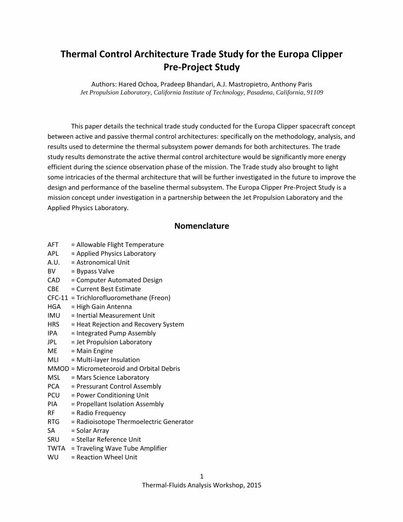
The reference spacecraft employs two wings of solar arrays with 53m2 of active area as its power
source, (Figure 1). But as an outer planet mission, power production and consumption are limited.
Additionally, thermal power demands tend to be one of the largest out of all the subsystems for outer
planet missions. Previous outer planet missions of similar sized spacecraft have employed passive
thermal control architectures: NASA’s Juno, Cassini, and Galileo. Up until very recently, these spacecraft
have always relied on the use of Radioisotope Thermoelectric Generators (RTGs) and other nuclear
sources for electrical and thermal power. Juno, slated to arrive at Jupiter in 2016, will be the first Jupiter
mission to use Solar Arrays. And while this spacecraft uses a passive thermal architecture of louvers,
doublers, and electrical heaters, the mission did not employ a Venus flyby in its trajectory. Europa
Clipper’s unique combination of a solar powered outer planet mission with a Venus flyby trajectory,
along with the success of mechanically pumped fluid loops used in recent interplanetary missions, have
provided enough need and merit for the mission to consider the use of an active thermal architecture
employing a Heat Rejection and Harvesting System (HRS). The main impetus behind this consideration is
the fluid loop’s (HRS’s) ability to very efficiently harvest waste heat from the power dissipating
components (e.g., avionics, telecom, etc.) for use in the non-dissipating subsystems, like the propulsion
module, leading to a significantly reduced power/energy demand for thermal control, when compared
to a passive system [2].
Figure 1: Europa Clipper Spacecraft Concept.
3 Thermal-Fluids Analysis Workshop, 2015
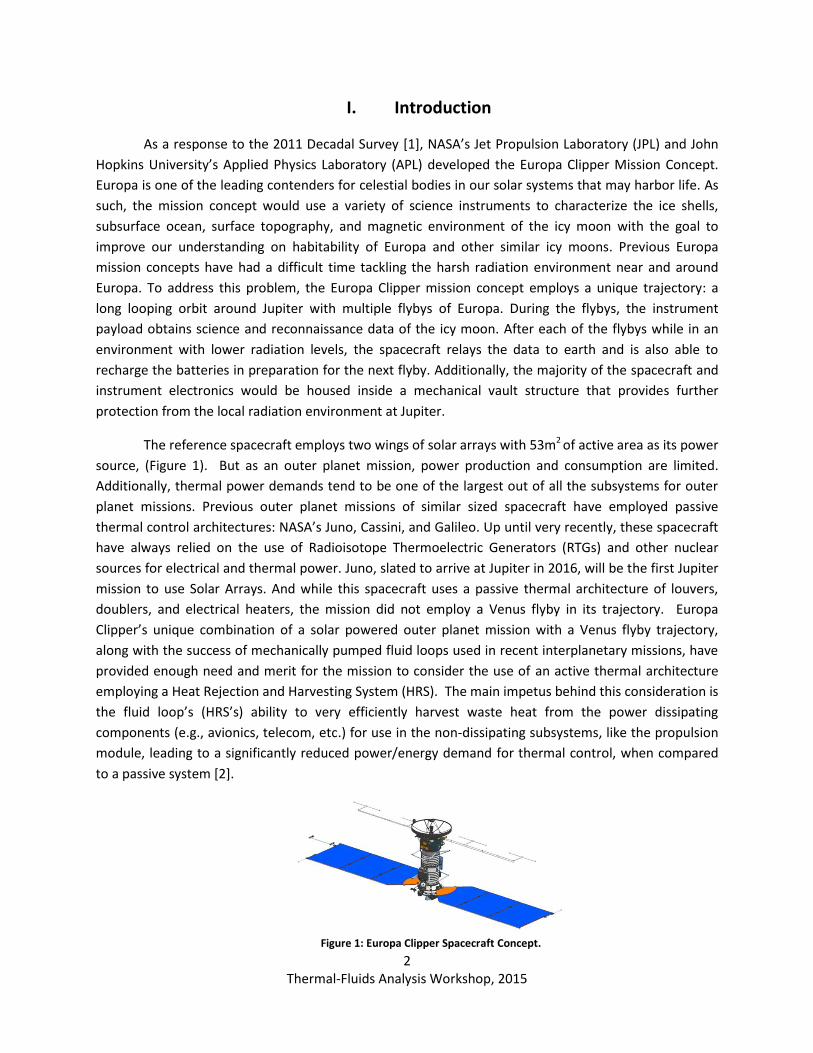
The HRS has been used in previous interplanetary missions, most notably the Mars Science
Laboratory (MSL). The HRS architecture, shown in Figure 2, consists of a mechanically pumped fluid loop
that harvests waste heat from electronic boxes (heat source) and delivers the heat to components
requiring thermal energy for temperature maintenance (heat sink). The fluid then continues on to a
radiator to reject surplus energy or bypasses the radiator to return to the pump; the percent flow
control of the fluid bypassing the radiator is done passively by a temperature sensitive bypass valve.
Implementation of the HRS architecture reduces electrical heater power demands by harvesting power
already being used by other spacecraft and instrument operations. Additionally, the HRS leads to a more
isothermal and thermally stable spacecraft.
Figure 2: Heat Rejection and Harvesting System (HRS).
There are technical and non-technical risks associated with both the HRS thermal architecture as
well as the passive one, which need to traded-off. Hardware fabrication and implementation can
potentially be a lot more strenuous and complex for an HRS architecture than for a passive thermal
architecture. In addition, tubing failure (e.g. due to micrometeoroid impact or other potential leak
paths), can lead to deleterious impacts on the spacecraft’s integrity. Finally, the HRS architecture has not
been used in radiation environments as extreme as those found near Jupiter; but results from initial
radiation risk mitigation studies are very promising. Hence, as the mission concept design and spacecraft
system needs and resources evolve, it is important to weigh the benefits and potential risks of an HRS
thermal architecture versus the passive one for the reference spacecraft and mission concept.
A study was commissioned by the project to trade the technical and non-technical aspects of
employing an active thermal architecture and a passive thermal architecture for the reference Europa
Clipper Spacecraft. This paper focuses on the technical aspects of the trade study – specifically on
predicting the power demands and accompanying mass impacts for both architectures.
II. Spacecraft Configuration
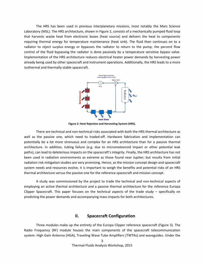
Three modules make up the entirety of the Europa Clipper reference spacecraft (Figure 3). The
Radio Frequency (RF) module houses the main components of the spacecraft telecommunication
system: High Gain Antenna (HGA), Traveling Wave Tube Amplifiers (TWTAs) and waveguides. Under the
4 Thermal-Fluids Analysis Workshop, 2015
RF module sits the avionics module which along with the Stellar Reference Units (SRUs), Inertial
Measurement Units (IMUs) and batteries, also houses the avionics vault where the majority of the
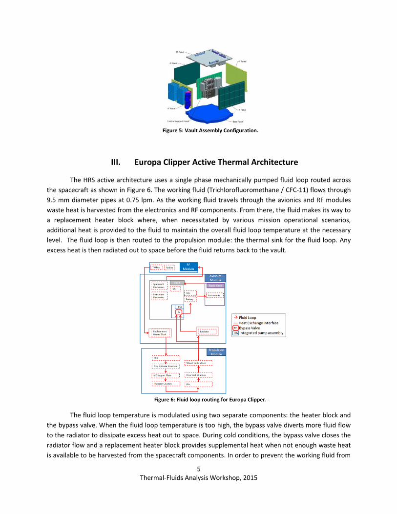
spacecraft and instrument electronics will be located, (Figure 4 and Figure 5). The majority of the
instruments are also expected to be located within the avionics module on a Europa Nadir pointing
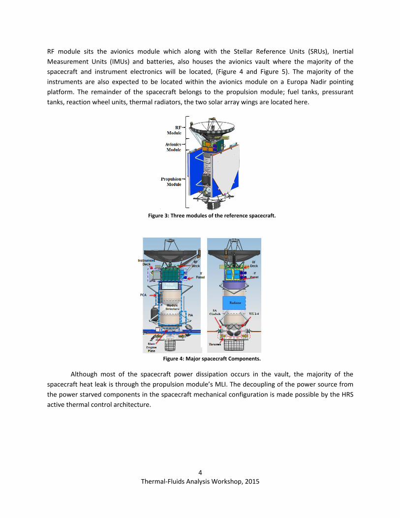
platform. The remainder of the spacecraft belongs to the propulsion module; fuel tanks, pressurant
tanks, reaction wheel units, thermal radiators, the two solar array wings are located here.
Figure 3: Three modules of the reference spacecraft.
Figure 4: Major spacecraft Components.
Although most of the spacecraft power dissipation occurs in the vault, the majority of the
spacecraft heat leak is through the propulsion module’s MLI. The decoupling of the power source from
the power starved components in the spacecraft mechanical configuration is made possible by the HRS
active thermal control architecture.
5 Thermal-Fluids Analysis Workshop, 2015
Figure 5: Vault Assembly Configuration.
III. Europa Clipper Active Thermal Architecture
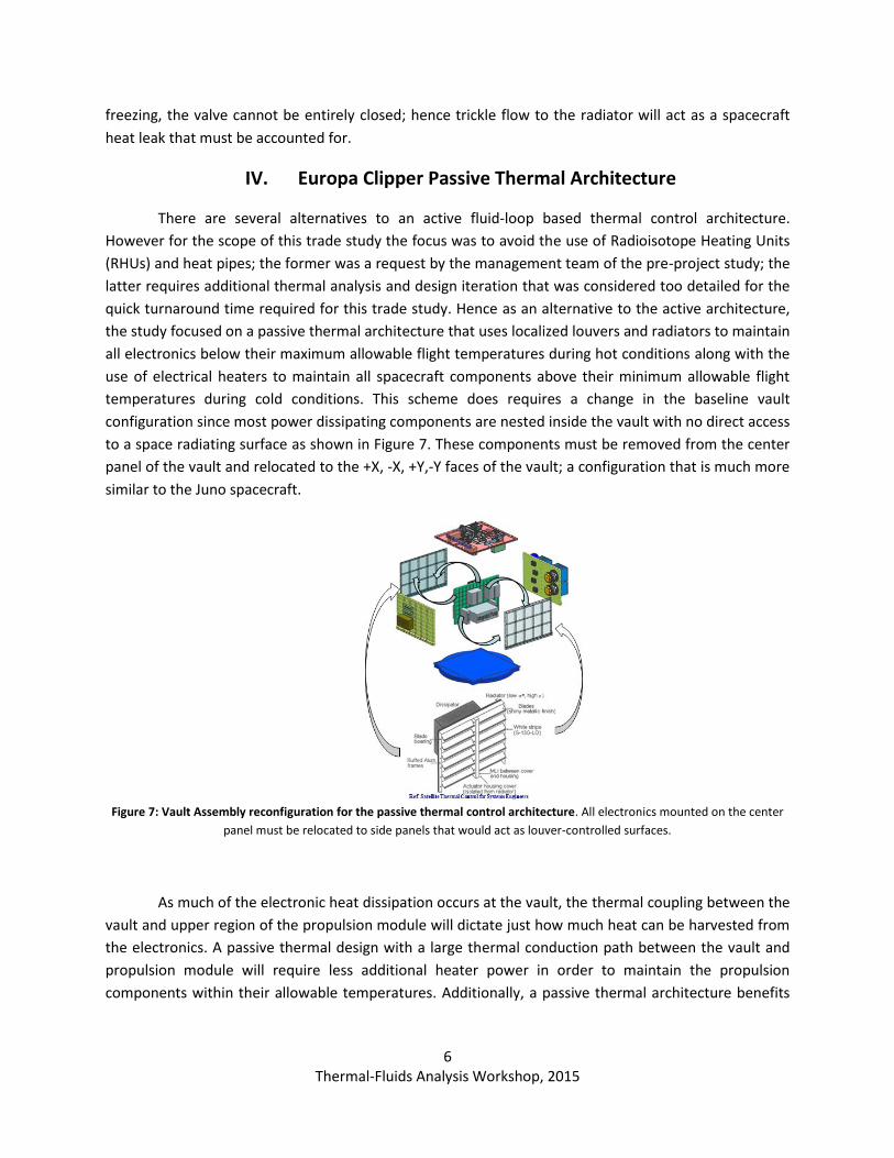
The HRS active architecture uses a single phase mechanically pumped fluid loop routed across
the spacecraft as shown in Figure 6. The working fluid (Trichlorofluoromethane / CFC-11) flows through
9.5 mm diameter pipes at 0.75 lpm. As the working fluid travels through the avionics and RF modules
waste heat is harvested from the electronics and RF components. From there, the fluid makes its way to
a replacement heater block where, when necessitated by various mission operational scenarios,
additional heat is provided to the fluid to maintain the overall fluid loop temperature at the necessary
level. The fluid loop is then routed to the propulsion module: the thermal sink for the fluid loop. Any
excess heat is then radiated out to space before the fluid returns back to the vault.
Figure 6: Fluid loop routing for Europa Clipper.
The fluid loop temperature is modulated using two separate components: the heater block and
the bypass valve. When the fluid loop temperature is too high, the bypass valve diverts more fluid flow
to the radiator to dissipate excess heat out to space. During cold conditions, the bypass valve closes the
radiator flow and a replacement heater block provides supplemental heat when not enough waste heat
is available to be harvested from the spacecraft components. In order to prevent the working fluid from
6 Thermal-Fluids Analysis Workshop, 2015
freezing, the valve cannot be entirely closed; hence trickle flow to the radiator will act as a spacecraft
heat leak that must be accounted for.
IV. Europa Clipper Passive Thermal Architecture
There are several alternatives to an active fluid-loop based thermal control architecture.
However for the scope of this trade study the focus was to avoid the use of Radioisotope Heating Units
(RHUs) and heat pipes; the former was a request by the management team of the pre-project study; the
latter requires additional thermal analysis and design iteration that was considered too detailed for the
quick turnaround time required for this trade study. Hence as an alternative to the active architecture,
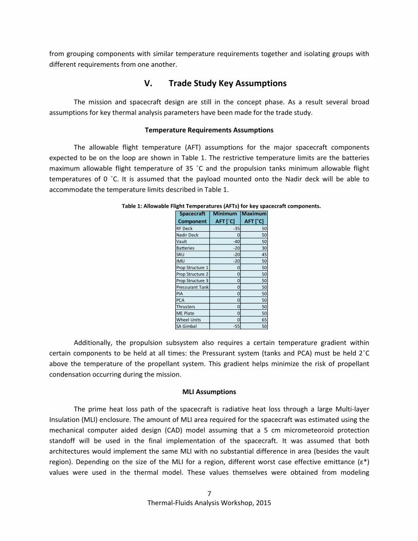
the study focused on a passive thermal architecture that uses localized louvers and radiators to maintain
all electronics below their maximum allowable flight temperatures during hot conditions along with the
use of electrical heaters to maintain all spacecraft components above their minimum allowable flight
temperatures during cold conditions. This scheme does requires a change in the baseline vault
configuration since most power dissipating components are nested inside the vault with no direct access
to a space radiating surface as shown in Figure 7. These components must be removed from the center
panel of the vault and relocated to the +X, -X, +Y,-Y faces of the vault; a configuration that is much more
similar to the Juno spacecraft.
Figure 7: Vault Assembly reconfiguration for the passive thermal control architecture. All electronics mounted on the center
panel must be relocated to side panels that would act as louver-controlled surfaces.
As much of the electronic heat dissipation occurs at the vault, the thermal coupling between the
vault and upper region of the propulsion module will dictate just how much heat can be harvested from
the electronics. A passive thermal design with a large thermal conduction path between the vault and
propulsion module will require less additional heater power in order to maintain the propulsion
components within their allowable temperatures. Additionally, a passive thermal architecture benefits
7 Thermal-Fluids Analysis Workshop, 2015
from grouping components with similar temperature requirements together and isolating groups with
different requirements from one another.
V. Trade Study Key Assumptions
The mission and spacecraft design are still in the concept phase. As a result several broad
assumptions for key thermal analysis parameters have been made for the trade study.
Temperature Requirements Assumptions
The allowable flight temperature (AFT) assumptions for the major spacecraft components
expected to be on the loop are shown in Table 1. The restrictive temperature limits are the batteries
maximum allowable flight temperature of 35 ˚C and the propulsion tanks minimum allowable flight
temperatures of 0 ˚C. It is assumed that the payload mounted onto the Nadir deck will be able to
accommodate the temperature limits described in Table 1.
Table 1: Allowable Flight Temperatures (AFTs) for key spacecraft components.
Additionally, the propulsion subsystem also requires a certain temperature gradient within
certain components to be held at all times: the Pressurant system (tanks and PCA) must be held 2˚C
above the temperature of the propellant system. This gradient helps minimize the risk of propellant
condensation occurring during the mission.
MLI Assumptions
The prime heat loss path of the spacecraft is radiative heat loss through a large Multi-layer
Insulation (MLI) enclosure. The amount of MLI area required for the spacecraft was estimated using the
mechanical computer aided design (CAD) model assuming that a 5 cm micrometeoroid protection
standoff will be used in the final implementation of the spacecraft. It was assumed that both
architectures would implement the same MLI with no substantial difference in area (besides the vault
region). Depending on the size of the MLI for a region, different worst case effective emittance (ε*)
values were used in the thermal model. These values themselves were obtained from modeling
RF Deck -35 50
Nadir Deck 0 50
Vault -40 50
Batteries -20 30
SRU -20 45
IMU -20 50
Prop Structure 1 0 50
Prop Structure 2 0 50
Prop Structure 3 0 50
Pressurant Tank 0 50
PIA 0 50
PCA 0 50
Thrusters 0 50
ME Plate 0 50
Wheel Units 0 65
SA Gimbal -55 50
Minimum
AFT [˚C]
Maximum
AFT [˚C]
Spacecraft
Component
8 Thermal-Fluids Analysis Workshop, 2015
guidelines developed for the Cassini spacecraft and provided in the Cassini Thermal Control Design
Handbook [3].
Thermal Conduction between Components
Because the spacecraft design has baselined the HRS as the spacecraft thermal control system,
much of the iteration focus between thermal and mechanical has been focused on accommodation of
the fluid loop to the regions and components needing thermal control. That being the case, not as much
iteration effort has been placed on determining the optimal thermal interface between different
spacecraft regions and components. In fact, a benefit of an HRS thermal architecture is that the
spacecraft mechanical design has a much more defined interface to the thermal control system via the
HRS fluid loop as opposed to in a passive architecture where both the mechanical and thermal designs
are deeply intertwined.
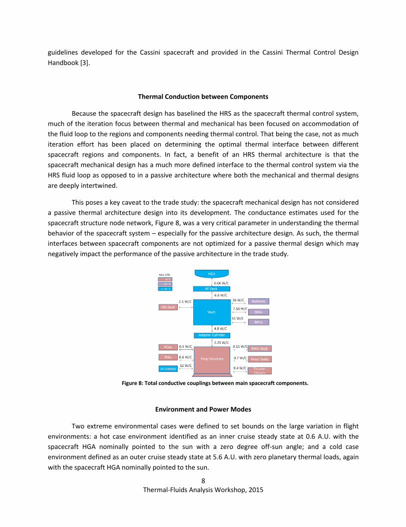
This poses a key caveat to the trade study: the spacecraft mechanical design has not considered
a passive thermal architecture design into its development. The conductance estimates used for the
spacecraft structure node network, Figure 8, was a very critical parameter in understanding the thermal
behavior of the spacecraft system – especially for the passive architecture design. As such, the thermal
interfaces between spacecraft components are not optimized for a passive thermal design which may
negatively impact the performance of the passive architecture in the trade study.
Figure 8: Total conductive couplings between main spacecraft components.
Environment and Power Modes
Two extreme environmental cases were defined to set bounds on the large variation in flight
environments: a hot case environment identified as an inner cruise steady state at 0.6 A.U. with the
spacecraft HGA nominally pointed to the sun with a zero degree off-sun angle; and a cold case
environment defined as an outer cruise steady state at 5.6 A.U. with zero planetary thermal loads, again
with the spacecraft HGA nominally pointed to the sun.
9 Thermal-Fluids Analysis Workshop, 2015
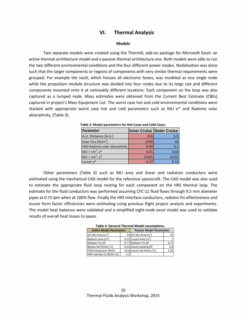
In addition, fifteen non-science nominal power scenarios for the mission concept had to be
distilled into the most bounding cases, shown in Table 2. Both a steady state scenario and a transient
scenario were identified for both outer cruise and inner cruise phases of the mission. The power
conditioning unit (PCU) located in the vault acts like a 10% tax on the total solar array power generation.
Hence the PCU is not in use when the spacecraft is under an Eclipse.
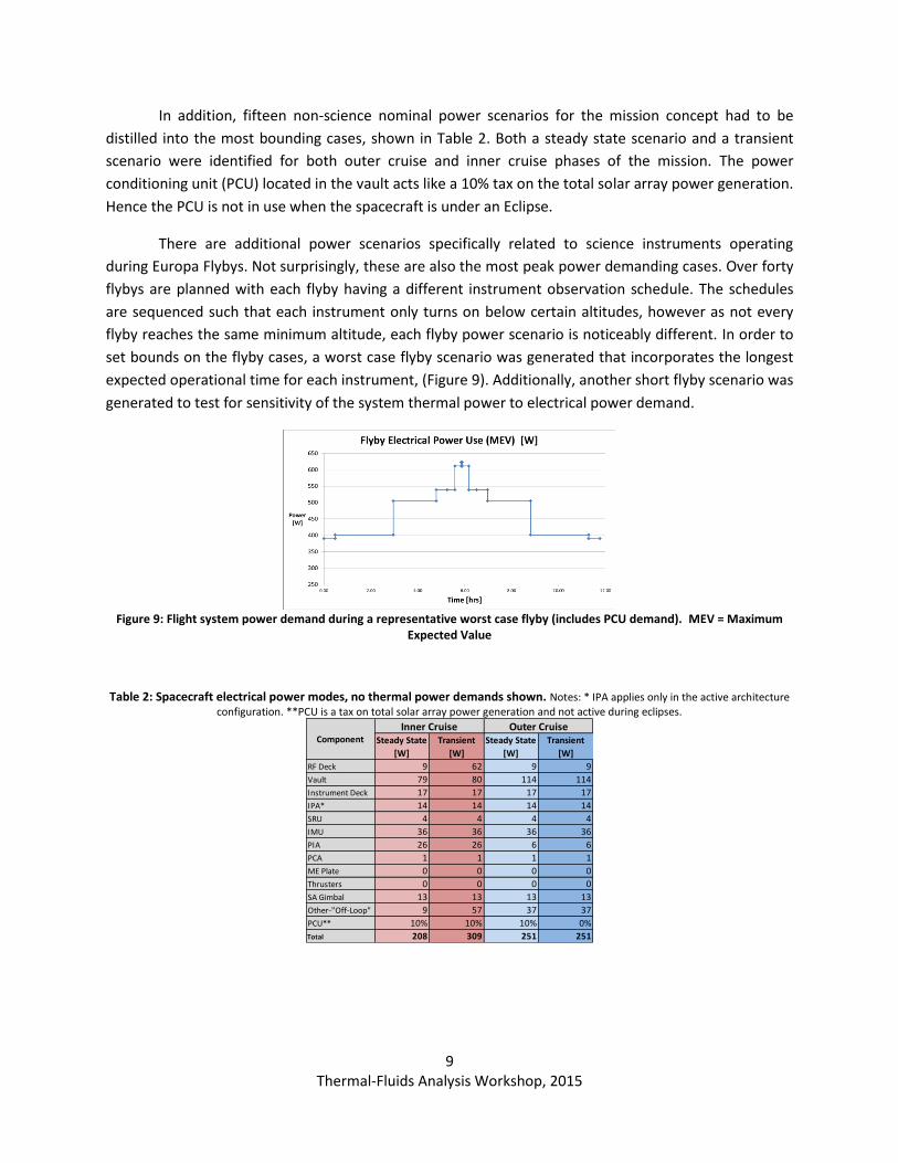
There are additional power scenarios specifically related to science instruments operating
during Europa Flybys. Not surprisingly, these are also the most peak power demanding cases. Over forty
flybys are planned with each flyby having a different instrument observation schedule. The schedules
are sequenced such that each instrument only turns on below certain altitudes, however as not every
flyby reaches the same minimum altitude, each flyby power scenario is noticeably different. In order to
set bounds on the flyby cases, a worst case flyby scenario was generated that incorporates the longest
expected operational time for each instrument, (Figure 9). Additionally, another short flyby scenario was
generated to test for sensitivity of the system thermal power to electrical power demand.
Figure 9: Flight system power demand during a representative worst case flyby (includes PCU demand). MEV = Maximum
Expected Value
Table 2: Spacecraft electrical power modes, no thermal power demands shown. Notes: * IPA applies only in the active architecture configuration. **PCU is a tax on total solar array power generation and not active during eclipses.
Steady State
[W]
Transient
[W]
Steady State
[W]
Transient
[W]
RF Deck 9 62 9 9
Vault 79 80 114 114
Instrument Deck 17 17 17 17
IPA* 14 14 14 14
SRU 4 4 4 4
IMU 36 36 36 36
PIA 26 26 6 6
PCA 1 1 1 1
ME Plate 0 0 0 0
Thrusters 0 0 0 0
SA Gimbal 13 13 13 13
Other-"Off-Loop" 9 57 37 37
PCU** 10% 10% 10% 0%
Total 208 309 251 251
ComponentInner Cruise Outer Cruise
10 Thermal-Fluids Analysis Workshop, 2015
VI. Thermal Analysis
Models
Two separate models were created using the ThermXL add-on package for Microsoft Excel: an
active thermal architecture model and a passive thermal architecture one. Both models were able to run
the two different environmental conditions and the four different power modes. Nodalization was done
such that the larger components or regions of components with very similar thermal requirements were
grouped. For example the vault, which houses all electronic boxes, was modeled as one single node
while the propulsion module structure was divided into four nodes due to its large size and different
components mounted onto it at noticeably different locations. Each component on the loop was also
captured as a lumped node. Mass estimates were obtained from the Current Best Estimate (CBEs)
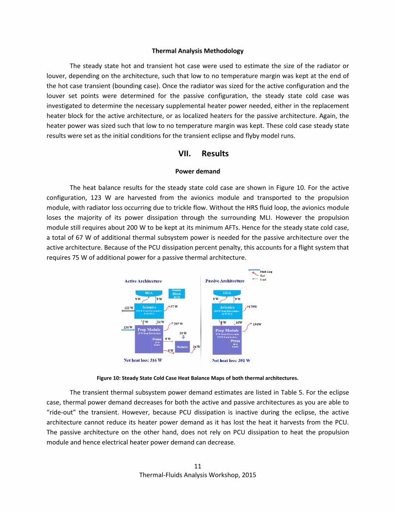
captured in project’s Mass Equipment List. The worst case hot and cold environmental conditions were
stacked with appropriate worst case hot and cold parameters such as MLI e* and Radome solar
absorptivity, (Table 3).
Table 3: Model parameters for Hot Cases and Cold Cases.
Other parameters (Table 4) such as MLI area and linear and radiation conductors were
estimated using the mechanical CAD model for the reference spacecraft. The CAD model was also used
to estimate the appropriate fluid loop routing for each component on the HRS thermal loop. The
estimate for the fluid conductors was performed assuming CFC-11 fluid flows through 9.5 mm diameter
pipes at 0.75 lpm when at 100% flow. Finally the HRS interface conductors, radiator fin effectiveness and
louver form factor efficiencies were estimating using previous flight project analysis and experiments.
The model heat balances were validated and a simplified eight-node excel model was used to validate
results of overall heat losses to space.
Table 4: General Thermal Model assumptions.
Parameter Inner Cruise Outer CruiseA.U. Distance [A.U.] 0.6 5.5
Solar Flux [W/m2] 3799 45
HGA Radome solar absorptivity 0.49 0.1
MLI > 1m2, e* 0.01 0.02
MLI < 1m2, e* 0.025 0.035
Louver e* 0.37 0.14
S/C MLI Area [m2] 33 S/C MLI Area [m2] 32
Radiator Area [m2] 0.32 Louver Area [m2] 1
Radiator Fin eff 0.77 Radiator Fin eff 0.77
Bypass Set Points [˚C] 0-15 Louver packing eff 0.8
Fluid Conductors [W/C] 16.6 Louver Set Points [˚C] 2-20
HRS Interface G [W/(m-C)] 2.2
Active Model Parameters Passive Model Parameters
11 Thermal-Fluids Analysis Workshop, 2015
Thermal Analysis Methodology
The steady state hot and transient hot case were used to estimate the size of the radiator or
louver, depending on the architecture, such that low to no temperature margin was kept at the end of
the hot case transient (bounding case). Once the radiator was sized for the active configuration and the
louver set points were determined for the passive configuration, the steady state cold case was
investigated to determine the necessary supplemental heater power needed, either in the replacement
heater block for the active architecture, or as localized heaters for the passive architecture. Again, the
heater power was sized such that low to no temperature margin was kept. These cold case steady state
results were set as the initial conditions for the transient eclipse and flyby model runs.
VII. Results
Power demand
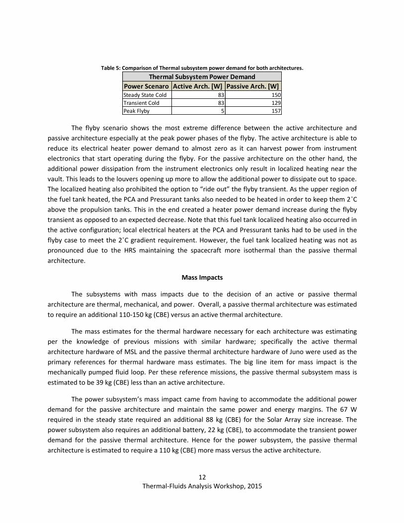
The heat balance results for the steady state cold case are shown in Figure 10. For the active
configuration, 123 W are harvested from the avionics module and transported to the propulsion
module, with radiator loss occurring due to trickle flow. Without the HRS fluid loop, the avionics module
loses the majority of its power dissipation through the surrounding MLI. However the propulsion
module still requires about 200 W to be kept at its minimum AFTs. Hence for the steady state cold case,
a total of 67 W of additional thermal subsystem power is needed for the passive architecture over the
active architecture. Because of the PCU dissipation percent penalty, this accounts for a flight system that
requires 75 W of additional power for a passive thermal architecture.
Figure 10: Steady State Cold Case Heat Balance Maps of both thermal architectures.
The transient thermal subsystem power demand estimates are listed in Table 5. For the eclipse
case, thermal power demand decreases for both the active and passive architectures as you are able to
“ride-out” the transient. However, because PCU dissipation is inactive during the eclipse, the active
architecture cannot reduce its heater power demand as it has lost the heat it harvests from the PCU.
The passive architecture on the other hand, does not rely on PCU dissipation to heat the propulsion
module and hence electrical heater power demand can decrease.
12 Thermal-Fluids Analysis Workshop, 2015
Table 5: Comparison of Thermal subsystem power demand for both architectures.
The flyby scenario shows the most extreme difference between the active architecture and
passive architecture especially at the peak power phases of the flyby. The active architecture is able to
reduce its electrical heater power demand to almost zero as it can harvest power from instrument
electronics that start operating during the flyby. For the passive architecture on the other hand, the
additional power dissipation from the instrument electronics only result in localized heating near the
vault. This leads to the louvers opening up more to allow the additional power to dissipate out to space.
The localized heating also prohibited the option to “ride out” the flyby transient. As the upper region of
the fuel tank heated, the PCA and Pressurant tanks also needed to be heated in order to keep them 2˚C
above the propulsion tanks. This in the end created a heater power demand increase during the flyby
transient as opposed to an expected decrease. Note that this fuel tank localized heating also occurred in
the active configuration; local electrical heaters at the PCA and Pressurant tanks had to be used in the
flyby case to meet the 2˚C gradient requirement. However, the fuel tank localized heating was not as
pronounced due to the HRS maintaining the spacecraft more isothermal than the passive thermal
architecture.
Mass Impacts
The subsystems with mass impacts due to the decision of an active or passive thermal
architecture are thermal, mechanical, and power. Overall, a passive thermal architecture was estimated
to require an additional 110-150 kg (CBE) versus an active thermal architecture.
The mass estimates for the thermal hardware necessary for each architecture was estimating
per the knowledge of previous missions with similar hardware; specifically the active thermal
architecture hardware of MSL and the passive thermal architecture hardware of Juno were used as the
primary references for thermal hardware mass estimates. The big line item for mass impact is the
mechanically pumped fluid loop. Per these reference missions, the passive thermal subsystem mass is
estimated to be 39 kg (CBE) less than an active architecture.
The power subsystem’s mass impact came from having to accommodate the additional power
demand for the passive architecture and maintain the same power and energy margins. The 67 W
required in the steady state required an additional 88 kg (CBE) for the Solar Array size increase. The
power subsystem also requires an additional battery, 22 kg (CBE), to accommodate the transient power
demand for the passive thermal architecture. Hence for the power subsystem, the passive thermal
architecture is estimated to require a 110 kg (CBE) more mass versus the active architecture.
Power Scenaro Active Arch. [W] Passive Arch. [W]Steady State Cold 83 150
Transient Cold 83 129
Peak Flyby 5 157
Thermal Subsystem Power Demand
13 Thermal-Fluids Analysis Workshop, 2015
Due to the quick turnaround time of the trade study, only a zeroth order estimate could be
completed for the mechanical subsystem’s mass impact. Mechanical accommodation of a passive
thermal architecture would require changes in the vault configuration; relocating the electronics boxes
from the center panel of the vault to the outer panels requires an increase in mounting area for the
outer panels. Additional mechanical accommodations may also be deemed necessary (such as doublers
on mounting surfaces). For the mechanical subsystem, the passive thermal architecture is estimated to
require 40-80 kg (CBE) of additional mass versus the active thermal architecture.
Hence although the thermal subsystem’s mass is less for a passive architecture, the additional
mass needed for mechanical and power to accommodate the architecture is substantially more. An
overall flight system mass upper of 110kg-150 kg (CBE) is expected for a passive thermal architecture.
VIII. Conclusion:
An active thermal control active architecture using an HRS fluid loop was traded with a passive
thermal architecture for the Europa Clipper reference spacecraft. The thermal subsystem power
demand estimate is lower for the active architecture than the passive architecture: 67W, 46W, and
113W less for the cold case steady state, transient eclipse cold case, and the peak flyby case. The
difference in power demands is due to the HRS architecture able to harvest waste heat from the
electronics; during the flyby case the instrument electronics supply additional waste heat that
substantially reduces electrical heater power demand for the active architecture. Additionally,
substantial localized heating in the fuel tank occurs in the passive architecture. This requires
supplemental heater power to maintain the PCA and pressurant tanks 2˚C above the fuel tank.
The results of the power analysis were used to determine solar array and battery mass impacts.
To maintain the same mass margins, the power subsystem was found to require an additional 110 kg
(CBE) of mass for the passive thermal architecture versus the active architecture.
Acknowledgments
The development and analysis described in this paper was carried out at the Jet Propulsion
Laboratory, California Institute of Technology, under a contract with the National Aeronautics and Space
Administration. The authors express their thanks to Daniel Lok at Applied Science Laboratory, Bruce
Williams at Applied Physics Laboratory, Matthew Spaulding at JPL, Alexander Eremenko at JPL, Antonio
Ulloa-Severino at JPL, Roxanne Arellano, and the rest of the Europa Clipper Mission Concept team.
© 2015 California Institute of Technology. Government sponsorship acknowledged.
14 Thermal-Fluids Analysis Workshop, 2015
References
[1] Visions and Voyages for Planetary Science in the Decade 2013-2022, National Research Council of the National Academies, NASA. Website: http://solarsystem.nasa.gov/2013decadal/ [2] Bhandari, P., “An Innovative Very Low Thermal Power Waste Heat Recovery System for Thermal Control of Deep Space Missions - A Thermal Flask in Space”,” 45th International Conference on Environmental Systems, Bellevue, WA, July 2015 [3] Stultz, J. et al., “Cassini Thermal Design Handbook”, Jet Propulsion Laboratory, California Institute of Technology, Pasadena, CA [4] “Europa Clipper Science and Reconnaissance Payload Proposal Information Package”, Jet Propulsion Laboratory, California Institute of Technology, Pasadena, CA, May 2014 [5] Karam R., et al. “Satellite Thermal Control for Systems Engineers”, American Institute of Aeronautics and Astronautics, 1998