Embed Size (px)
Citation preview
Thermal Buckling Analysis of Laminated Composite Shell
Panel Embedded with Shape Memory Alloy Fibre under
TD and TID
Rohit Kumar Singh
Thermal Buckling Analysis of Laminated Composite Shell
Panel Embedded with Shape Memory Alloy Fibre under
TD and TID
Thesis Submitted to
National Institute of Technology, Rourkela
for the award of the degree
of
Master of Technology
In Mechanical Engineering with Specialization
“Machine Design and Analysis”
by
Rohit Kumar Singh
Roll No. 212me1284
Under the Supervision of
Prof. Subrata Kumar Panda
Department of Mechanical Engineering
National Institute of Technology Rourkela
Odisha (India) -769 008
June 2014

NATIONAL INSTITUTE OF TECHNOLOGY
ROURKELA
CERTIFICATE
This is to certify that the work in this thesis entitled ―Thermal Buckling Analysis of
Laminated Composite Shell Panel Embedded with Shape Memory Alloy (SMA) Fibre
under TD and TID‖ by Mr. Rohit Kumar Singh (212ME1284) has been carried out under
my supervision in partial fulfilment of the requirements for the degree of Master of
Technology in Mechanical Engineering with Machine Design and Analysis specialization
during session 2012 - 2014 in the Department of Mechanical Engineering, National Institute of
Technology, Rourkela.
To the best of my knowledge, this work has not been submitted to any other
University/Institute for the award of any degree or diploma.
Date: Prof. S. K. Panda
(Assistant Professor)
Dept. of Mechanical Engineering
National Institute of Technology
Rourkela-769008
IV
SELF DECLARATION
I, Mr Rohit Kumar Singh, Roll No. 212ME1284, student of M. Tech (2012-14), Machine
Design and Analysis at Department of Mechanical Engineering, National Institute of
Technology Rourkela do hereby declare that I have not adopted any kind of unfair means
and carried out the research work reported in this thesis work ethically to the best of my
knowledge. If adoption of any kind of unfair means is found in this thesis work at a later
stage, then appropriate action can be taken against me including withdrawal of this thesis
work.
NIT Rourkela
02 June 2014
Rohit Kumar Singh

V
ACKNOWLEDGEMENT
My first thanks are to the Almighty God, without whose blessings, I wouldn't have been
writing this ―acknowledgments". I am extremely fortunate to be involved in an exciting
and challenging research project work on ―Thermal Buckling Analysis of Laminated
Composite Shell Panel Embedded with Shape Memory Alloy (SMA) Fibre under TD
and TID‖. It has enriched my life, giving me an opportunity to work in a new
environment of ANSYS and MATLAB. This project increased my thinking and
understanding capability as I started the project from scratch.
I would like to express my greatest gratitude to my supervisor Prof. S . K. Panda, for
his excellent guidance, valuable suggestions and endless support. He has not only been a
wonderful supervisor but also an honest person. I consider myself extremely lucky to be
able to work under guidance of such a dynamic personality. He is one of such genuine
person for whom my words will not be enough to express.
I would like to express my sincere thanks to Vishesh R. Kar, Vijay K. Singh and P.V.
Katariya (My seniors) and all my classmates for their precious suggestions and
encouragement to perform the project work. I am very much thankful to them for giving
their valuable time for me.
Finally, I express my sincere gratitude to my parents for their constant
encouragement and support at all phases of my life.
Rohit Kumar Singh
VI
Abstract
Laminated composite shell panels are increasingly used in aeronautical, marine and
mechanical industries as well as in other fields of modern technology because of its advance
mechanical properties. It is well known that the composites have high strength to weight
ratio and stiffness to weight ratio as compared to any conventional materials like concrete,
metal, and wood. As the uses of the composites in different industries have increased which
leads to their analysis through mathematical, experimental and/or simulation based model
for accurate design and subsequent manufacturing. The structural components of aircraft,
launch vehicle and missiles are subjected to various types of combined loading and exposed
to large acoustic, vibration, inertia excitation during their service life. In addition to that the
structural components are also exposed to elevated thermal environment due to the
aerodynamic heating. This often changes the original geometry of the panel due to excess
deformation and the structural performances reduce. In this work, thermal buckling
behaviour of laminated composite curved panel embedded with shape memory alloy fibre
(SMA) is investigated. The material properties of composite laminate and SMA fibres are
taken as temperature dependent. The mathematical model is developed based on higher
order shear deformation theory (HSDT) to count the exact flexure of the laminate. The
buckling behaviour is evaluated based on the Green-Lagrange strain-displacement equations
for in-plane strains to account the large deflections under uniform temperature loading. The
nonlinear material behaviour of shape memory alloy is introduced through a marching
technique. The responses are obtained using variational principle in conjunction with
suitable isoparametric finite element modelling based on the MATLAB code. In addition to
that, a simulation model is also being developed in ANSYS environment using ANSYS
parametric design language code for laminated composites curved panel and the
corresponding responses are compared with those available literatures. The effects of layup
sequence, thickness ratio, ply angle, support conditions and temperature dependence
material properties on thermal buckling load is obtained and discussed.
Keywords: Laminated panel, HSDT, Green-Lagrange nonlinearity, FEM, Thermal buckling,
ANSYS, APDL code, MATLAB.
VII
Contents
Title Page (I)
Certificate of Approval (III)
Self-Declaration (IV)
Acknowledgement (V)
Abstract (VI)
Contents (VII)
List of Symbols (XI)
List of Tables (XIV)
List of Figures (XV)
Chapter 1 Introduction (1-13)
1.1 Overview (1)
1.2 Introduction of Finite Element Method and ANSYS (6)
1.3 Motivation of the Present Work (7)
1.4 Objectives and Scope of the Present Thesis (8)
1.5 Organisation of the Thesis (9)
Chapter 2 Literature Review (11-17)
2.1 Introduction (11)
2.2 Thermal Buckling Analysis (12)
2.3 Thermal buckling analysis of laminated composite (12)
without SAM fibre
2.4 Thermal buckling analysis of laminated composite (16)
embedded with SAM fibre
Chapter 3 General Mathematical Formulation (18-27)
VIII
3.1 Introduction (18)
3.2 Assumptions (19)
3.3 Geometry of the Shell (19)
3.4 Displacement Field (20)
3.5 Strain-Displacement Relation (20)
3.6 Material Properties of Composite Embedded with SMA Fibre (22)
3.7 Constitutive Relation (22)
3.8 Energy Calculation (23)
3.9 Finite Element Formulation (24)
3.10 Governing Equation (25)
3.11 Solution Technique (25)
3.12 Support Conditions (26)
3.13 Computational Investigations (26)
3.14 Summary (27)
Chapter 4 Thermal Buckling Analysis of Laminated Composite Shell Panels (28-43)
4.1 Introduction (28)
4.2 Governing Equation and Solution (29)
4.3 Results and Discussions (29)
4.3.1 Convergence and Validation Study of Buckling (30)
4.3.1.1 Convergence and comparison study of thermal buckling
temperature parameter (30)
4.3.1.2 Influence of plate orientation on the thermal buckling
temperature parameter (30)
4.3.1.3 Comparison of thermal buckling temperature parameter
with thickness ratio (31)
4.3.1.4 Influence of material property on the thermal buckling
strength (32)
4.3.1.5 Convergence and validation study of thermal buckling
temperature parameter (33)
4.3.1.6 Convergence and validation study of thermal buckling
temperature parameter (34)
IX
4.3.1.7 Comparison of critical buckling temperature parameter
for different thickness ratio (35)
4.3.2 Numerical Examples
4.3.2.1 Cylindrical shell panel (35)
4.3.2.1.1 Influence of thickness ratio (a/h)on the
thermal buckling strength (35)
4.3.2.1.2 Influence of curvature ratio (R/a) on the
thermal buckling strength (36)
4.3.2.1.3 Influence of material property on the
thermal buckling strength (38)
4.3.2.1.4 Convergence study of thermal buckling
temperature parameter (38)
4.3.2.2 Spherical shell panel (39)
4.3.2.2.1 Influence of thickness ratio (a/h)on the
thermal buckling strength (39)
4.3.2.2.2 Influence of curvature ratio (R/a) on the
thermal buckling strength (40)
4.3.2.2.3 Influence of material property on the
thermal buckling strength (41)
4.3.2.2.4 Convergence study of thermal buckling
temperature parameter (42)
4.4 Conclusions (42)
Chapter 5 Thermal Buckling Analysis of Laminated Shell Panels
Embedded with SMA fibre (43-46)
5.1 Introduction (43)
5.2 Governing Equation and Solution (44)
5.3 Results and Discussions (44)
5.3.1 Convergence and validation study of buckling (45)
5.3.1.1 Convergence study of buckling temperature of composite
panel embedded with SMA fibres (45)
X
5.3.1.2 Influence of thickness ratio (a/h) on the buckling temperature
parameter (46)
5.4 Conclusions (46)
Chapter 6 Closure (47-50)
6.1 Concluding Remarks (47)
6.2 Significant Contribution of the Thesis (47)
6.3 Future Scope of the Research (48)
References (51-55)
Appendix (68-72)
XI
List of Symbols
Most of the symbols are defined as they occur in the thesis. Some of most common
symbols, which are used repeatedly, are listed below:
x, y, z Co-ordinate axis
u, v and w Displacements corresponding to x, y and z directions, respectively
u0, v0 and w0 In-plane and transverse displacements of a point (x, y) on the mid-
plane
x , and y Rotations of normal to the mid-plane
x , y , x and y Higher order terms of Taylor series expansion
Rx, Ry Principal radii of the curvatures of the shell panel
E1, E2 and E3 Young‘s modulus
G12, G23 and G13 Shear modulus
12 , 23 and 13 Poison‘s ratios
a, b and h Length, width and thickness of the shell panel
l Linear strain vectors
Stress vector at mid-plane
Displacement vector
Q
Transformed reduced elastic constant
lB Linear strain displacement matrix
D Rigidity matrix
XII
SK Linear stiffness matrix
GK Geometric stiffness matrix
F Global force vector
US.E. Strain energy
T Function of thickness co-ordinate
Thermal expansion co-efficient
Density of the material
T Kinetic energy
W Work done
a/h Thickness ratio
R/a Curvature ratio
E1/E2 Modular ratio
cr Non-dimensional buckling temperature
Subscript
l Linear
2 Anti- Symmetric
S Symmetric
i Node number
XIII
Abbreviation
CLPT Classical laminate plate theory
FSDT First order shear deformation theory
HSDT Higher order shear deformation theory
APDL ANSYS parametric design language
SSSS All edges simply supported
CCCC All edges clamped
HHHH All edges hinged
Eq. Equation
GPa Giga Pascal
XIV
List of Tables
Table No. Page No.
4.1 Influence of plate orientation on the thermal buckling temperature
parameter
(31)
4.2 Buckling temperature variation with thickness ratio variation (31)
4.3 Variation of thermal buckling temperature for different parameter (33)
4.4 Influence of thickness ratio (a/h) on the thermal buckling strength (35)
4.5 Influence of thickness ratio (a/h) on the thermal buckling strength (37)
4.6 Influence of curvature ratio (R/a) on the thermal buckling strength (38)
4.7 Variation of thermal buckling temperature for different parameter (39)
4.8 Influence of thickness ratio (a/h) on the thermal buckling strength (40)
4.9 Influence of curvature ratio (R/a) on the thermal buckling strength (41)
4.10 Variation of thermal buckling temperature for different parameter (42)
5.1 Composite/ SMA material properties (45)
5.2 Influence of thickness ratio and boundary condition on thermal
buckling strength
(47)
XV
List of Figures
Figure No. Page No.
1.1 SMA Lattice Structure at Different Phase (3)
1.2 Phase Transformation in SMA and Different Lattice Structure (4)
1.3 Shows the phase transformation and different phase temperature (5)
1.4 SHELL281 Geometry [75] (7)
3.1 Laminated composite shell panel embedded with SMA fibre (19)
4.1 Convergence of thermal buckling temperature parameter (λT)
with different mesh divisions of plate
(30)
4.2 Convergence study of thermal buckling temperature parameter
(λT) with different mesh divisions and stacking sequence
(34)
4.3 Convergence and validation study of thermal buckling
temperature parameter (λT) with different mesh divisions and
boundary condition
(35)
4.4 Convergence study of thermal buckling temperature parameter
(λT) with different mesh divisions and boundary condition
(39)
4.5 Convergence study of thermal buckling temperature parameter
(λT) with different mesh divisions and boundary condition
(43)
5.1 Convergence study of critical buckling temperature (Tcr) (46)
1
CHAPTER 1
INTRODUCTION
1.1 Overview
Laminated composite shell panel are extensively used in many industries, building,
bridges and structures such as boat hulls, racing car body and storage tank and some of the
advance application of laminated composite shell panel is used in naval and space projects.
Composites are made up of two constituent elements matrix and fibre. Matrix provides
compliant support for the reinforcement and distributes the load evenly in all direction, as it
surrounds the fibre whose function is to bear the load. Composite materials has a following
property which make it attractive to the researcher such as its volume to its weight ratio, low
co-efficient of thermal expansion, outstanding elastic properties and good corrosion and
chemicals resistant. Laminated composite panel is assemblies of layers of fibrous composite
material which can be used for specific purpose. Laminated composites panel are extremely
lightweight with respect to conventional materials like concrete, metal, and wood. Because
of above properties it is being used in like aerospace, marine, modern automobile and
modern structure. Shell panel is a curved thin and thick structure having single or multilayer
of anisotropic or orthotropic materials subjected to different loads. The shell panel can be
classified according to its curvatures such as flat panel (as its both the radius is zero),
cylindrical (one radius is zero), spherical (where both the radius is equal), conical (where
one radius is zero and another varies linearly with the axial length). The shell panel has
considerably higher membrane stiffness than that of the bending stiffness that‘s why it can
withstand a large value of membrane strain energy without large deformations. The external
skins of aircraft/spacecraft/automobile are having panel type of geometry and made of the
thin laminated composites.
If a shell is subjected to compressive load, it will be store as strain energy and on
further increases of the load leads to bending in the structure, progressively leads to a
buckling failure of the structure. Hence, the buckling plays an important role in the design
and analysis of the structures. Basically two types of buckling occur in structural member
2
namely, eigenvalue/ bifurcation buckling and non-linear/ limit point buckling. The
bifurcation buckling is a form instability in which there is a sudden change of shape of the
structure due to the axial compressive/tensile load. However, in the limit point buckling
there is no sudden change of shape but it deviates from the primary equilibrium path after
reaching the critical load i.e., known as ―snap through‖. Buckling doesn‘t mean failure of
structural component as it is capable enough bear more load even after the point of buckling.
To increases the structural performance of the structure against thermal loading,
conventional structural undergoes structural stiffening and constraining, but this
conventional method leads to increase in weight and temperature rise, it is substantially high
enough to create enough problem than that of its advantages. So to solve such problems
smart material have been introduced which contains actuator, sensor and microprocessor
capability like pH-sensitive polymers, piezoelectric material (produces electricity in
response to stress), functionally graded material (material changes property in thickness
direction), shape memory alloy (material property changes with the variation with
temperature) and photomechanical material (material-change shape under exposed to light).
These new materials have the property that unable designer to change the external as well as
internal condition which leads to advancement in the structural performance. The smart
material has the great affinity to change shape, frequency, stiffness, buckling, damping, and
other mechanical parameter with respect to change in electrical field, temperature or
magnetic field. In the present investigation SMA embedded composite shell panel is used to
regulate reaction of the shell panel exposed to thermal load.
SMA has been researched for last 30 years due to its attractive functional properties.
The shape memory effect i.e. the property of recovering the deformation when exposed to
heating up to a certain elevated temperature, was first discovered in an alloy of Cadmium
(52.5%) and Gold (47.5%) by Otsuka and Wayman in 1932. Again this behaviour was
observed in Cu-Zn in 1938 and later on this property was discovered and enriched by United
States naval ordnance laboratory in 1962 in alloy of nickel (48%)-titanium(52%) and
commercialized it under the trade name of Nitinol. SMAs have the better competency for
engineering application because it is highly ductile at low temperature shape, recovery
capability is 10% strain which is high enough, large corrosion resistance and biomedical
application.
3
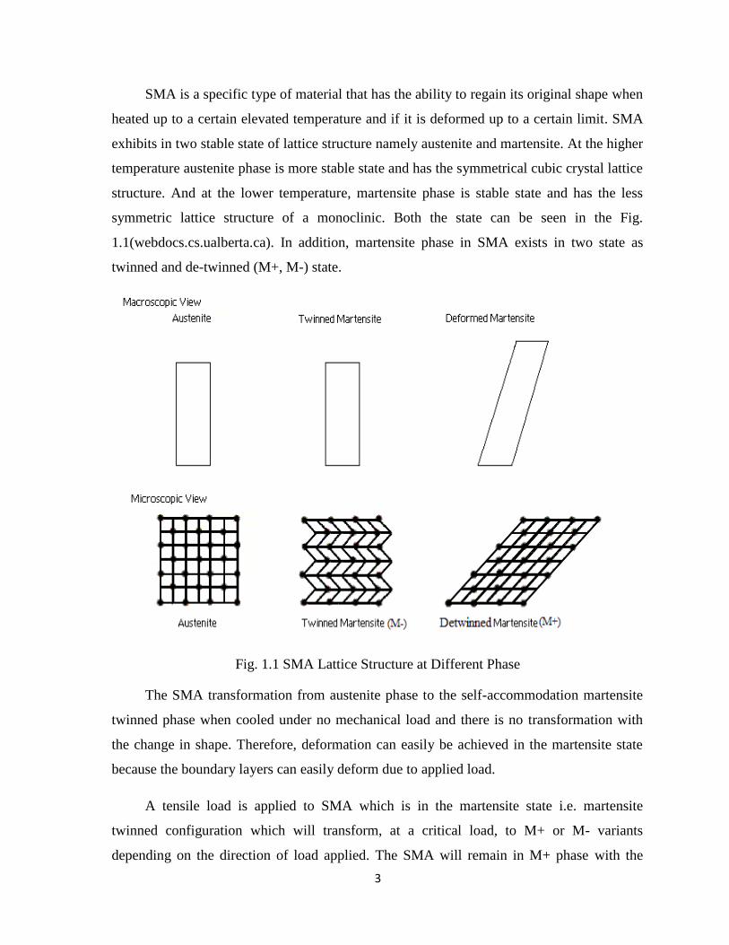
SMA is a specific type of material that has the ability to regain its original shape when
heated up to a certain elevated temperature and if it is deformed up to a certain limit. SMA
exhibits in two stable state of lattice structure namely austenite and martensite. At the higher
temperature austenite phase is more stable state and has the symmetrical cubic crystal lattice
structure. And at the lower temperature, martensite phase is stable state and has the less
symmetric lattice structure of a monoclinic. Both the state can be seen in the Fig.
1.1(webdocs.cs.ualberta.ca). In addition, martensite phase in SMA exists in two state as
twinned and de-twinned (M+, M-) state.
Fig. 1.1 SMA Lattice Structure at Different Phase
The SMA transformation from austenite phase to the self-accommodation martensite
twinned phase when cooled under no mechanical load and there is no transformation with
the change in shape. Therefore, deformation can easily be achieved in the martensite state
because the boundary layers can easily deform due to applied load.
A tensile load is applied to SMA which is in the martensite state i.e. martensite
twinned configuration which will transform, at a critical load, to M+ or M- variants
depending on the direction of load applied. The SMA will remain in M+ phase with the
4
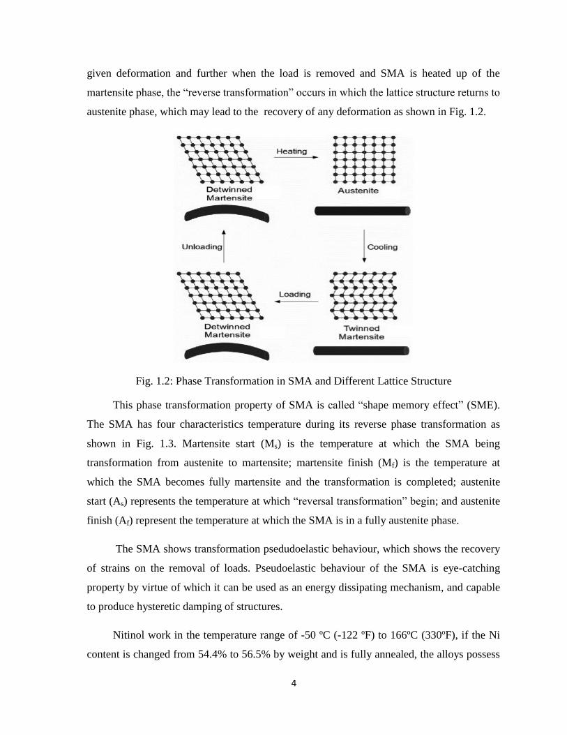
given deformation and further when the load is removed and SMA is heated up of the
martensite phase, the ―reverse transformation‖ occurs in which the lattice structure returns to
austenite phase, which may lead to the recovery of any deformation as shown in Fig. 1.2.
Fig. 1.2: Phase Transformation in SMA and Different Lattice Structure
This phase transformation property of SMA is called ―shape memory effect‖ (SME).
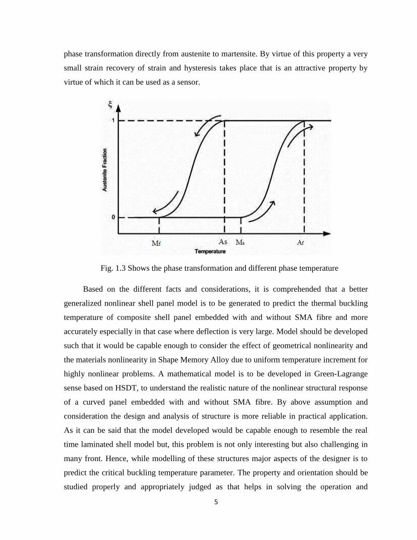
The SMA has four characteristics temperature during its reverse phase transformation as
shown in Fig. 1.3. Martensite start (Ms) is the temperature at which the SMA being
transformation from austenite to martensite; martensite finish (Mf) is the temperature at
which the SMA becomes fully martensite and the transformation is completed; austenite
start (As) represents the temperature at which ―reversal transformation‖ begin; and austenite
finish (Af) represent the temperature at which the SMA is in a fully austenite phase.
The SMA shows transformation psedudoelastic behaviour, which shows the recovery
of strains on the removal of loads. Pseudoelastic behaviour of the SMA is eye-catching
property by virtue of which it can be used as an energy dissipating mechanism, and capable
to produce hysteretic damping of structures.
Nitinol work in the temperature range of -50 ºC (-122 ºF) to 166ºC (330ºF), if the Ni
content is changed from 54.4% to 56.5% by weight and is fully annealed, the alloys possess
5
phase transformation directly from austenite to martensite. By virtue of this property a very
small strain recovery of strain and hysteresis takes place that is an attractive property by
virtue of which it can be used as a sensor.
Fig. 1.3 Shows the phase transformation and different phase temperature
Based on the different facts and considerations, it is comprehended that a better
generalized nonlinear shell panel model is to be generated to predict the thermal buckling
temperature of composite shell panel embedded with and without SMA fibre and more
accurately especially in that case where deflection is very large. Model should be developed
such that it would be capable enough to consider the effect of geometrical nonlinearity and
the materials nonlinearity in Shape Memory Alloy due to uniform temperature increment for
highly nonlinear problems. A mathematical model is to be developed in Green-Lagrange
sense based on HSDT, to understand the realistic nature of the nonlinear structural response
of a curved panel embedded with and without SMA fibre. By above assumption and
consideration the design and analysis of structure is more reliable in practical application.
As it can be said that the model developed would be capable enough to resemble the real
time laminated shell model but, this problem is not only interesting but also challenging in
many front. Hence, while modelling of these structures major aspects of the designer is to
predict the critical buckling temperature parameter. The property and orientation should be
studied properly and appropriately judged as that helps in solving the operation and
6
problem. The previous parametric study helps us to find the result by considering the
consequences of loading and limiting conditions. Problem should be studied thoroughly
before the analysis and modelling.
1.2 Introduction of Finite Element Method and ANSYS
With the advancement in technology, the design process is too close to precision, so
the finite element method (FEM) is used widely and capable to draw complicated structure
and this is very trusted tool for designing of any shape and structure. It plays an important
role in predicting the responses of various products, parts, assemblies and subassemblies.
Nowadays, FEM is extensively used by all advanced industries which save their huge time
of prototyping with reducing the cost due to physical test and increases the innovation at a
faster and more accurate way. There are many optimized finite element analysis (FEA) tools
are available in the market and ANSYS is one of them which is acceptable to many
industries and analysts.
Nowadays, ANSYS is being used in different engineering fields such as power
generation, electronic devices, transportation, and household appliances as well as to
analyse the vehicle simulation and in aerospace industries. ANSYS gradually entered into a
number of fields making it convenient for fatigue analysis, nuclear power plant and medical
applications. ANSYS is also very useful in electro thermal analysis of switching elements of
a super conductor, ion projection lithography, detuning of an HF oscillator.
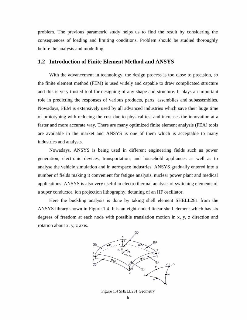
Here the buckling analysis is done by taking shell element SHELL281 from the
ANSYS library shown in Figure 1.4. It is an eight-noded linear shell element which has six
degrees of freedom at each node with possible translation motion in x, y, z direction and
rotation about x, y, z axis.
Figure 1.4 SHELL281 Geometry
7
xo = Element x-axis if element orientation is not provided.
x = Element x-axis if element orientation is provided.
1.3 Motivation of the Present Work
The laminated composite shell panels are of great attention to the designers because of
its efficient lightweight to strength ratio, high-impact strength, dimensional stability,
corrosion resistance and low thermal conductivity. In the past few years, use of composite
structures has increased a lot especially in aeronautical/aerospace engineering which forced
the engineers for its analysis. These structural components are undergone to various types of
combined loading and goes through high temperature during their service period, which may
leads to change in the shape of the geometry of structure. The changes in panel geometry
and the interaction with loading condition affect the buckling responses greatly.
In order to achieve the light weight structures for stringent demand of weight
reduction in the advanced engineering structures to conserve energy, the laminated
composites consisting of multiple layers are extensively employed and their usage will
continue to grow as structural members. It is also important to mention that, these laminated
composites are weak in shear and highly flexible in nature as compared to any other metallic
plate/shell. To obtain the accurate prediction of responses of laminated composites, it is
necessary and essential requirement that the displacement model must be capable to take
care of the consequence of shear deformation. In this regard a HSDT is most desirable. The
geometry of the shell panel alters and stiffness matrix associated with the material are no
more linear due to excess deformations and this effects has to be appropriately considered in
the analysis. Buckling of structures have been received a considerable attention not only due
to their wide range application, but also the challenging problems with interesting
behaviour. In most of the literature, the geometry matrix associated in buckling is modelled
taking into account for the non-linearity in the von-Karman sense. But the nonlinearity in
von-Karman sense may not be appropriate enough for the realistic prediction of their
responses. Since the existing studies considering all these aspects are not sufficient enough
to predict the accurate structural responses so, there is a need of a better general model for
the more accurate estimation of the behaviour of laminated shell panels.
8
1.4 Objective and Scope of the Present Thesis
This study aims to develop a general mathematical model for laminated composite
curved panel under uniform temperature loading based on the HSDT displacement field
model. The Green-Lagrange type of strain displacement relations are employed to account
the geometrical distortion. A suitable finite element model is approached to discretise the
present model and responses are obtained, subsequently. The effect of different types of
panel geometries (cylindrical, spherical and flat) and other geometrical parameters (aspect
ratio, thickness ratio, curvature ratio, support condition and stacking sequence) on the
thermal buckling responses of the laminated composites shell panel embedded with/without
SMA, are analysed and discussed. Point-wise details of the present study are listed below:
A mathematical model is developed based on the HSDT mid-plane kinematics with
the incorporation of Green-Lagrange strain terms.
The finite element solutions are provided by using a nine noded quadrilateral element
with nine degrees of freedom per node.
A computer code has been developed in MATLAB environment to obtain the desired
responses.
The present study also extended for composite shell panel modelled through APDL
code in ANSYS 13.0 environment.
Finally, the parametric study of laminated composite panel embedded with/without
SMA has been done by using APDL model and developed HSDT model.
1.5 Organization of the Thesis
The overview and motivation of the present work followed by the objectives and scope
of the present thesis are discussed in this chapter. The background and state of the art of the
present problem by various investigators related to the scope of the present area of interest
are addresses in this chapter. This chapter divided into five different sections, the first
section, a basic introduction about problem and theories used in past. In the section two,
some important contributions for thermal buckling behaviour of laminated composite
structures are discussed. In the section three, a brief introduction of finite element method
9
and finite element analysis software ANSYS is presented. The motivation of the present
work is discussed in fourth and in fifth objective and scope of present work is incorporated.
Some critical observations are discussed in the final section. The remaining part of the thesis
are organised in the following fashion.
In chapter 2, brief introduction of the previous publish literature has been presented
along with their theory and method adopted for the analysis by the authors. The chapter is
subdivided in two parts consisting of thermal buckling analysis of composite shell panel
without SMA and thermal buckling analysis of composite shell panel embedded with SMA.
In chapter 3, a general mathematical formulation for the thermal buckling of laminated
composite panel, by modelling in the framework of the HSDT under the uniform
temperature distribution. The Green-Lagrange type strain displacement relations are
considered to account the geometrical nonlinearity arising in the shell panel due to excess
deformation. The steps of various energy calculations, governing equation and solution steps
are discussed. Subsequently, the boundary condition and computational investigation are
discussed.
Chapter 4, illustrate the thermal buckling responses of laminated composite panels for
various panel geometries such as cylindrical, spherical and flat panel are discussed. Detailed
parametric studies of material and geometrical parameters are also discussed.
Enhancement of thermal buckling of laminated composite panels for different panel
geometries and the influence of geometrical and material properties on the panel responses
under the influence of Shape Memory Alloy are discussed in Chapter 5.
Chapter 6 summarizes the whole work and it contains the concluding remarks based
on the present study and the future scope of the work.
Some important books and publications referred during the present study have been
listed in the References section.
In order to achieve the objective and scope of the present work discussed above in this
chapter, there is need to know the state of art of the problem for that a detailed review of
earlier work done in the same field have been discussed thoroughly in the next chapter.
10
CHAPTER 2
LITERATURE REVIEW
2.1 Introduction
Flat/curved composite panels and their combination are used at the place where the
light weight places an important role like aerospace, marine, mechanical and modern
automotives. The curved geometry and/or meridional discontinuity of the panel due to the
the joints increases the geometrical complexity and adversely affect the stability. Structures
are very often subjected to buckling and post-buckling. They are also subjected to high
thermal load during their working period. Due to the boundary constraints, the development
compressive thermal membrane state of stress may lead to structural instability/buckling of
the structure.
In general, laminated structural component are under combined effect of aerodynamic,
mechanical and thermal loading condition during their operational life for which a
significant difference exist between their deformed and undeformed shape and the linear
strain displacement relation are not only able to explain the state variable. The strain
displacement relation and the displacement relations and the displacement model should be
sufficient enough to accomplish the excess thermal deformation and/or the large amplitude
vibration of the structure for an accurate prediction. The laminated structure are highly
flexible in nature and when working under various loading condition as discussed then the
geometrical nonlinearity in von-Karman sense is unrealistic in nature for the mathematical
modelling purpose. Hence, there is a need of rigorous study of different structural behavior
using a better nonlinear model to characterise the post-buckling characteristic in details.
A lot of literatures are presented on thermal buckling of laminated composite shell
panel embedded with and without SMA fibre by taking the nonlinearity in von-Karman
sense in the framework of various classical and shear deformation theories such as CLT,
FSDT, LWT and HSDT. Relatively very less number of studies is reported on the buckling
temperature of laminated shell panel with and without SMA by taking the nonlinearity in
von-Karman sense or Green-Lagrangian sense in the framework of the HSDT. In the
11
following section of this chapter a brief contextual of various type of problem and
comprehensive reviews of existing literatures is discussed. The review of literature is carried
out for buckling for composite panel with and without SMA fibre for the present
investigation. In continuation buckling characteristic due to thermal load is discussed in this
addition. Finally, a heading is devoted for the critical observations obtained from the
discussed literature.
2.2 Thermal Buckling Analysis
The buckling is nothing but the geometrical shape change of structural component and
is usually nonlinear in nature. A numerous analyses have been reported in the literature on
the buckling by taking the geometric matrix and nonlinear stiffness matrices in von-Karman
sense based in various theories such as classical laminated theory and the shear deformation
theories. Lots of literatures are there on buckling of composite shell panel due to thermal
loadings. A few of them are discussed here.
2.2.1 Thermal buckling analysis of laminated composite without SAM fibre
Matsunaga (2005) predict the buckling stress and natural frequencies of laminated
composite beams based on the power series expansion. Sahin (2005) studied buckling
behaviour of symmetric and anti-symmetric cross-ply laminated hybrid composite plates
with a hole using FEM based on the FSDT model. Shariyat (2007) investigated post
buckling behavior of laminated imperfect plates based on the layer wise theory and von
Karman nonlinear strain–displacement equations. The composite material properties are
calculated based on the temperature effect for the computation. Chen and Chen (1991)
reported thermal post-buckling behavior of laminated composite plate using Hermitian
polynomials based on the temperature dependent material properties. The elastic properties
of the medium are assumed to be temperature dependent. Shukla and Nath (2001) computed
the buckling and post-buckling load parameters of angle-ply laminated plates analytically
under thermo-mechanical loading. The non- linearity in geometry matrix due to excess
thermal/mechanical deformation is taken in von-Karman sense in the framework of the
FSDT. Thankam et.al. (2003) investigated thermal buckling and post-buckling behaviour of
cross ply and angle-ply laminates.
12
Modified feasible direction method has been used by Topal and Uzman (2008) for
thermal buckling load optimization of laminated flat/cylindrical panels to maximize the
critical temperature capacity of laminated structures. Shiau (2010) reported critical buckling
load and modes of two different laminations (cross-ply and angle-ply). Shen (1997)
analyzed the buckling and post-buckling behavior of laminated composite plate based on
HSDT and von-Karman nonlinear kinematics. Shen (2001) reported buckling and post
buckling temperature and load deflection curve of laminated composite plates based on
Reddy‘s (2003) third composite and sandwich panels based on the global higher order shear
deformation theory by solving order shear deformation theory. Ovesy et. al. (2009) predicted
thermal buckling load used the concept of principle of minimum potential energy and an
eigen-value analysis is subsequently carried out along with implementing the higher order
semi-analytical finite strip method and concluded that classical laminated plate theory
(CLPT) predict the buckling load more accurately. Singh and Shukla (2012) studied stability
of orthotropic cross ply laminated composite plates subjected to thermal and mechanical.
Shen (2001) employed the perturbation technique and thermal buckling and post buckling
temperature load deflection curved is drawn by an iterative numerical procedure by the
FSDT model.
Thermal buckling responses of anti-symmetric angle-ply laminated plate are obtained
by Chang and Leu (1991) based on a higher-order displacement field and solved using 3-D
elasticity solution. Lee (1997) studied thermal buckling behaviour of laminated composite
plates based on the layerwise theory by using FEM steps. Vosoughi et al. (2012) presented
thermal buckling and post-buckling load parameters of laminated composite beams. The
buckling behaviour of composite plates is analysed by Jameel et al. (2012) under thermal
and mechanical loading. Buckling behaviour of laminated composite plate is studied by
Fazzolari et al. (2013) taking non- linearity in geometry matrix due to excess
thermal/mechanical deformation in von-Karman sense in the framework of the HSDT.
Shadmehri et al. (2013) reported stability behaviour of conical composite shells subjected to
axial compression load using linear strain–displacement relations in the framework of the
FSDT. Kheirikhah et al. (2012) studied bi-axial buckling behaviour of laminated composite
and sandwich plates using the von-Karman kinematic non-linearity in the framework of the
HSDT. Nali et al. (2011) obtained buckling responses of laminated plates using von-Karman
13
nonlinear kinematic in the framework of thin plate theory. Singh et al. (2013) reported the
buckling behaviour of laminated composite plates subjected to thermal and mechanical
loading using mesh-less collocation method in the framework of the HSDT.
In addition to the above, some researcher have also analysed the buckling behaviour of
laminated structures under mechanical loading using the same type of geometrical
nonlinearity and in-plane mechanical loading. Khdeir and Librescue (1988) investigated the
buckling and the free vibration responses of symmetric cross-ply laminated elastic plates
based on the HSDT mid-plane kinematics. The buckling behaviour of cross-ply laminated
conical shell panels subjected to axial compression is studied by Abediokhchi et al. (2013)
in the framework of the classical shell theory. Komur et al. (2010) obtained buckling
responses of laminated composite plates with an elliptical/circular cut-out using FEM and
governing equations are solved using Newton–Raphson method. Seifi et al. (2012) reported
buckling responses of composite annular plates under uniform internal and external radial
edge loads in the framework of the CLPT. Khalili et al. (2013) obtained buckling load
parameters of laminated rectangular plate on Pasternak foundation using the Lindstedt–
Poincare perturbation technique. Tang and Wang (2011) studied buckling behaviour of
symmetrically laminated rectangular plates with in-plane compressive loadings using the
Rayleigh–Ritz method in the framework of the CLPT.
2.2.2 Thermal buckling and post-buckling analysis of laminated composite
embedded with SAM fibre
The buckling and post-buckling strength of laminated structure can be enhanced
comprehensive by employing SMA in thermal environment due to the inherent actuation
properties in the Chapter 1. Many studies are reported in the literature, to exploit the actual
strength of SMA against different type geometric and environmental condition. Lee and choi
(1999) developed an analytical formula to predict the buckling load and enhancement of
post-buckling strength of composite beams by using SMA. Poon et al. (2004) developed a
simple equation to study the effect of size on the actuation of SMA wire actuator inside the
hybrid composites numerically. Naseer et al. (2005) studied the plastic behaviour of SMA
due to very high strain rate subjected to compressive load experimentally. Burton et al.
(2006) studies numerically the healing of cracks in the laminated composite structural
14
components embedded with SMA wires by varying the temperature based on FEM.
Thomson and loughlam (1997 and 2001) analysed the adaptive post-buckling responses of
laminated composite carbon fibres embedded with prestrain SMA fibres and predicted the
enhancement of post-bucking strength of laminated composites and non-uniform
temperature profile within the laminates using FEM under uniaxial load.
The SMA can be used as a smart material for the futuristic structures, where light
weight and controllability are main factor of considerations. Based on that, few researched
have studies on the feasibility of SMA application especially in aerospace structures.
Loughlan et al. (2002) investigated the enhancement of buckling load and suppression post-
buckling deflection based on various experimental studies and discussed the feasibility of
application of SMA in aerospace structure as a smart material. Hartl and Lagoudas (2007)
published a detailed review article on the SMA application in aerospace structures as a
multifunctional material.
Park et. al. (2005) studied the consequence of SMA on critical temperature, thermal
post-buckling deflection, natural frequency and critical dynamic pressure of SMA composite
plate subjected to aerodynamics and thermal loading. Kumar and Singh (2009) reported
thermal buckling and post-buckling behaviour of laminated composite flat panel embedded
with SMA fibre using Newton-Raphson method under uniform thermal load.
Ganilova and Cartmell (2009) studied the vibration behaviour of SMA by developing
mathematical model by means of WKB- Galerkin method. Here damping and stiffness are
considered time dependent. Burton et al.(2004) studied the crack healing behaviour under
the influence of SMA while simulation is done in a ABAQUS. Panda and Singh (2013)
investigated the vibrational behaviour of laminated composite panel embedded with SMA
fibre by taking the geometrical nonlinearily in Green-Lagrange sense. Qiao et al. (2013)
studied the behaviour of shape memory polymer composites (SMPCs) and calculated the
postbuckling temperature using FEM. Muhammad et al. (2000) observed the buckling and
postbuckling behaviour of SMA under the varying value of slenderness ratio (L/k) and
compared with some other materials.
Loughlan et al. (2002) investigated the consequence of temperature on buckling
behaviour of composite embedded with SMA. Thompson and Louhglan (2001) shown the
15
effect of restoration force on post-buckling response as the material is exposed to elevated
temperature and the result is compared with that of conventional material and structure.
Panda and Singh (2011) studied the thermal post-buckling strength of doubly curve in
Green-Lagrangian sense in framework of HSDT and effect of various geometrical
parameters. Lee et al. (2005) studied the behaviour of ferromagnetic shape memory alloy
(FSMA) by using ANSYS code result is compared with that of SMA and is illustrated
reliability of FSMA. Choi and Toi (2009) studied the 3-D superelastic behaviors of SMA
devices and calculated the various properties.
16
CHAPTER 3
GENERAL MATHEMATICAL FORMULATION
3.1 Introduction
Now days, high performance laminated structure and their components are designed
and used in many places like marine, space and many more. These structures are more
reliable and have more a load bearing capacity as they often account varying load such as
structural, thermal, large amplitude flexural vibration. Hence, the demand of detailed study
of such structure under above mentioned condition is increasing very rapidly and
significantly.
In general, nonlinearity in the structural analysis is of two type geometrical
nonlinearity and geometrical nonlinearity. As we all know that the total deformation
occurred in the material system is a sum of translational, rotation and distortion components
and if the structure undergoes severe nonlinearity then only two other component rather than
distortion component play important role to derive the actual strain- displacement relation.
The laminated composite structural components are highly flexible with respect to metallic
component so higher order nonlinear terms and large deformation terms in mathematical
modelling are important for an accurate analysis. As per detailed literature study in the
previous chapter clearly shows that many analyses have been done for many nonlinear
problems, but no study have been done using geometrical nonlinearity in Green-Lagrange
sense in the framework of HSDT for laminated composite shell panel embedded with and
without SMA fibre.
In this chapter general formulation of curved panel is developed on the basis of basic
assumptions. A FE model is produced to discretise the present model though chosen
displacement field. The geometrical nonlinearity in green-Lagrange sense and the material
nonlinearity for SMAs stress-strain relation are considered for the formulation and discussed
in this chapter. Finally, to solve the algebraic equations a direct iterative procedure is
adopted.
17
3.2 Assumptions
The following assumptions are taken for the mathematical formulation:
The middle panel of the curved panel is taken as the reference plane.
Every layer is assumed to be homogeneous and orthotropic whereas the layer bonded
together well.
Two dimensional approach has been adopted to model a three dimensional behaviour
of shell.
A uniform temperature field is taken for the analysis in the thickness direction.
The composite material properties are considered temperature dependent and
independent whereas the SMA material properties are taken temperature dependent.
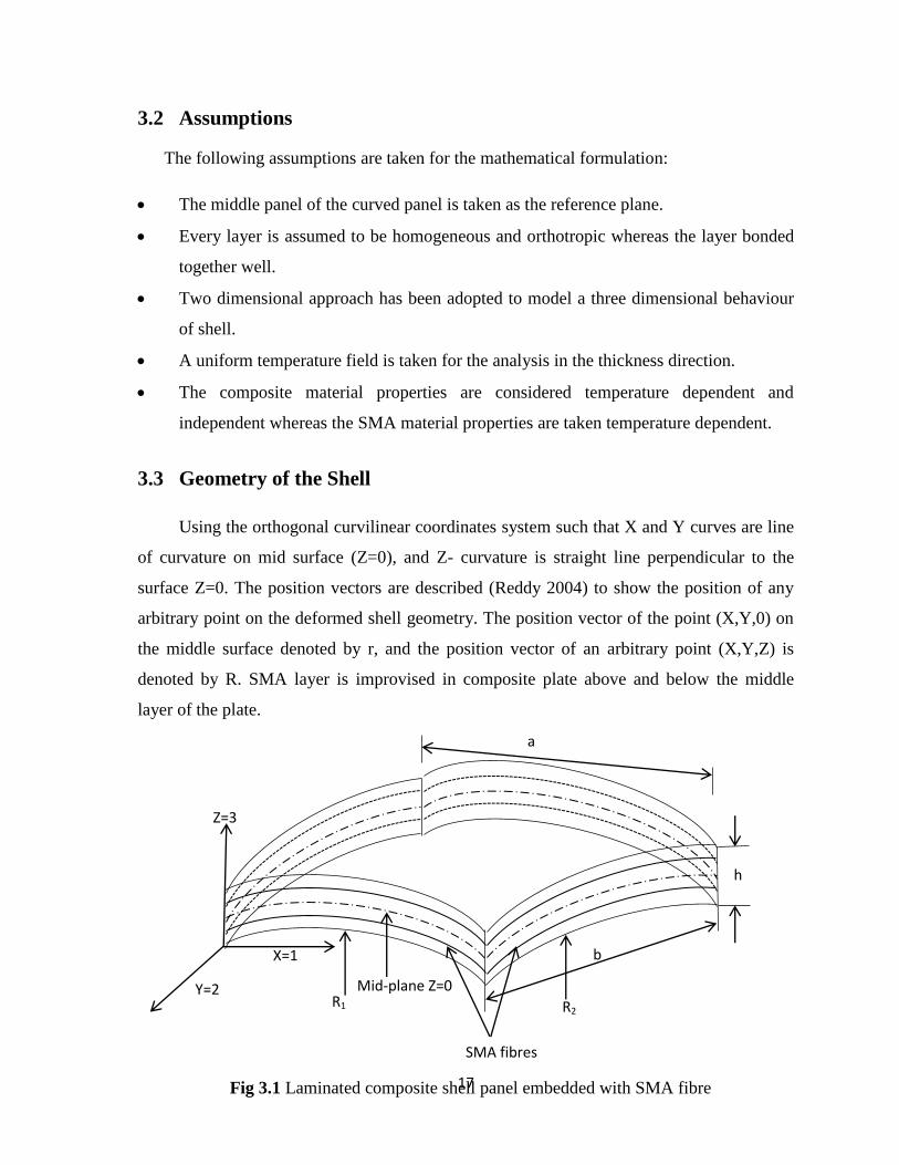
3.3 Geometry of the Shell
Using the orthogonal curvilinear coordinates system such that X and Y curves are line
of curvature on mid surface (Z=0), and Z- curvature is straight line perpendicular to the
surface Z=0. The position vectors are described (Reddy 2004) to show the position of any
arbitrary point on the deformed shell geometry. The position vector of the point (X,Y,0) on
the middle surface denoted by r, and the position vector of an arbitrary point (X,Y,Z) is
denoted by R. SMA layer is improvised in composite plate above and below the middle
layer of the plate.
R1
Z=3
Y=2
b
h
SMA fibres
X=1
Mid-plane Z=0
R2
a
Fig 3.1 Laminated composite shell panel embedded with SMA fibre
18
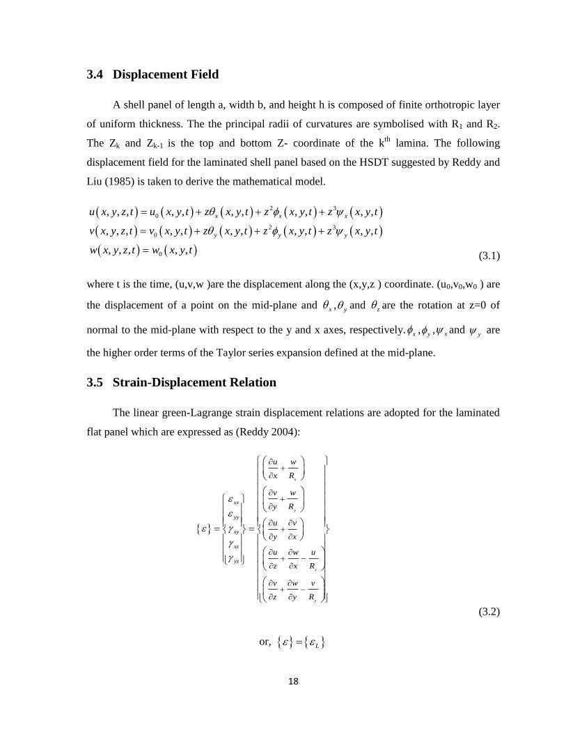
3.4 Displacement Field
A shell panel of length a, width b, and height h is composed of finite orthotropic layer
of uniform thickness. The the principal radii of curvatures are symbolised with R1 and R2.
The Zk and Zk-1 is the top and bottom Z- coordinate of the kth
lamina. The following
displacement field for the laminated shell panel based on the HSDT suggested by Reddy and
Liu (1985) is taken to derive the mathematical model.
2 3
0
2 3
0
0
, , , , , , , , , , ,
, , , , , , , , , , ,
, , , , ,
x x x
y y y
u x y z t u x y t z x y t z x y t z x y t
v x y z t v x y t z x y t z x y t z x y t
w x y z t w x y t
(3.1)
where t is the time, (u,v,w )are the displacement along the (x,y,z ) coordinate. (u0,v0,w0 ) are
the displacement of a point on the mid-plane and x ,y and z are the rotation at z=0 of
normal to the mid-plane with respect to the y and x axes, respectively. x ,y , x and
y are
the higher order terms of the Taylor series expansion defined at the mid-plane.
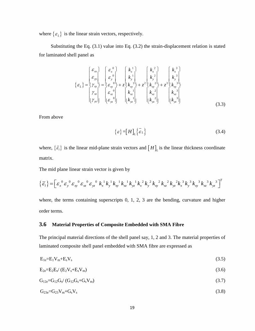
3.5 Strain-Displacement Relation
The linear green-Lagrange strain displacement relations are adopted for the laminated
flat panel which are expressed as (Reddy 2004):
x
y
x
y
xx
yy
xy
xz
yz
u w
x R
v w
y R
u v
y x
u w u
z x R
v w v
z y R
(3.2)
or, L
19
where L is the linear strain vectors, respectively.
Substituting the Eq. (3.1) value into Eq. (3.2) the strain-displacement relation is stated
for laminated shell panel as
(3.3)
From above
= LL
H
(3.4)
where, l is the linear mid-plane strain vectors and L
H is the linear thickness coordinate
matrix.
The mid plane linear strain vector is given by
0 0 0 0 0 1 1 1 1 1 2 2 2 2 2 3 3 3 3 3T
l x y xy xz yz x y xy xz yz x y xy xz yz x y xy xz yzk k k k k k k k k k k k k k k
where, the terms containing superscripts 0, 1, 2, 3 are the bending, curvature and higher
order terms.
3.6 Material Properties of Composite Embedded with SMA Fibre
The principal material directions of the shell panel say, 1, 2 and 3. The material properties of
laminated composite shell panel embedded with SMA fibre are expressed as
E1e=E1Vm+EsVs (3.5)
E2e=E2Es/ (E2Vs+EsVm) (3.6)
G12e=G12Gs/ (G12Gs+GsVm) (3.7)
G23e=G23Vm+GsVs (3.8)
0 1 2 3
0 1 2 3
2 30 1 2 3
0 1 2 3
0 1 2 3
xx x x x x
yy y y y y
xyL xy xy xy xy
xz xz xz xz xz
yz yz yz yz yz
k k k
k k k
z z zk k k
k k k
k k k
20
ν12e=ν12mVm+νsVs (3.9)
α1e=(E1mα1mVm+EsαsVs)/E1 (3.10)
α2e=α2mVm+αsVs (3.11)
where subscript ‗m‘ and ‗s‘ indicates the composite matrix and SMA fibres, respectively.
Here E, G, ν and α are the Young‘s modulus, shear modulus, Poisson‘s ratio and thermal
expansion co-efficient respectively. Vm and Vs are the volume fraction of the composite
matrix and SMA fibre, respectively.
3.7 Constitutive Relation
For orthotropic lamina the stress-strain relations for kth
layer of SMA embedded
composite matrix in material coordinate axes under constant temperature field are expressed
as (Park et al. 2004):
kk kk k k k k
r s mmmQ V Q V T (3.12)
where, 1 2 6 5 4
k T is the total stress vector and {σ∆r} is the recovery stress
produced in SMA fibre due to the temperature change (∆T) and 1 2 6 5 4
k T
is the strain vector, in the kth
layer. In addition, k
Q ,
k
mQ and
1 2 122k T
m m mm are the transferred reduced stiffness matrix of SMA embedded
lamina, transferred reduced stiffness matrix of composite matrix and the transformed
thermal expansion coefficient vector of the kth
layer, respectively. ∆T is the change in
temperature.
(3.13)
Thermal in-plane generated force can be obtained by integrating the equation (3.12) in
the thickness direction and can be represented in matrix form as:
1
1
3
2
1
12
(1, , )
2
k
k
k
t r mzN k kk
t r s m mm
k z
t r m
r
N N
M M V Q z z V Tdz
P P
21
where tN, tM
and tP are the resultant vectors of in-plane forces, moment and
transverse shear force due to the temperature change ( T ) in composite matrix whereas
rN, rM
and rP are general in SMA fibre due to the recovery stress.
3.8 Energy Calculation
As s first step, the global displacement vector represented in the matrix form as
u
v f
w
(3.14)
where f and 0 0 0
T
x y x y x yu v w are the function of
thickness coordinate and the displacement vector at mid plane of the panel, respectively.
The kinetic energy expression (T) of a thermal buckled laminated panel can be expressed as:
1
2
T
V
T dV
(3.15)
where , , and
are the density and the first order differential of the displacement vector
with respect to time, respectively.
Using Eq. (3.14) and (3.15) the kinetic energy can be expressed as
1
1
1 1
2 2
k
k
Tz TNT k
kA z A
T f f dz dA m dA
(3.16)
where, 1
1
k
k
zNT k
k z
m f f dz
is the inertia matrix.
The strain energy (US.E.) of thermally buckled composite panel embedded with SMA
fibre can be expressed as:
22
. .
1
2
T
S E iv i
U dV (3.17)
By substituting the strain and the stress expression of Eqs. (3.4) and (3.12) into Eq.
(3.17) the strain energy expression as:
. .
1
2
kkk k kT k
S E r s mmv mU Q V Q V T dV
(3.18)
The work done (W∆T) by thermal membrane force due to the temperature rise (∆T) can
be expressed in linearized form by following the procedure as adopted by Cook et al. (2000)
and conceded to
1
2
T
T G G G
A
W D dA (3.19)
where G is geometric strain and GD is the material property matrix.
3.9 Finite Element Formulation
In this analysis, a nine nodded isoparametric quadrilateral Lagrangian element have 81
degree of freedom (DOFs) per element is employed. The details of the element can be seen
in Cook et al. (2000).
The global displacement vector 0 0 0
T
x y x y x yu v w will
be represented as stated below by using FEM
i iN (3.20)
where iN and i are the nodal interpolation function and displacement vector for ith
node, respectively.
By substitution of Eq. (3.21) into Eqs. (3.16), (3.18) and (3.19) the kinetic energy,
strain energy and the work done expressions can be further expressed as
T
i i
A
T N m N dA
(3.21)
23
. .
1
2
TT
S E r ti iAU B D B dA F F (3.22)
1
2
TT
l G G G
A
W B D B dA (3.23)
where L
r L rA
F B N dA , L
l L lA
F B N dA ,
1
1
1
[ ]k
k
N z T
L Lzk
D H Q H dz
where LB and GB are the product form of the different operator and nodal interpolation
function in the linear strain terms and geometric strain terms, respectively.
3.10 Governing Equation
By using the Hamilton‘s principle, the equation of buckling for the composite will be
expressed as:
2
1
0t
tLdt (3.24)
where L=T-(US.E. +W∆T)
3.11 Solution Technique
To analyse the thermal buckling of composite panels embedded with SMA fibres, will
be given by
0s cr G sK K (3.25)
For the linear eigenvalue problem without SMA is solved by dropping the term of
term of recovery strain.
3.12 Support Condition
The main purpose of boundary condition is to avoid rigid body motion as well as to
decrease the number of unknowns of a system for ease in calculating and also the singularity
in the matrix equation can be avoided. In the present analysis, kinematical constrain
24
condition are applied as the model is developed using the displacement based finite element
i.e. all the unknown are defined of displacement only.
The boundary condition used for the present analysis is expressed below. However the
mathematical formulation which is general in nature does not put any limitations.
a) Simple supported boundary conditions (S):
u0=w0=θy= θz =øy=ψy=0 at x=0,a
v0=w0=θx= θz =øx=ψx=0 at y=0,b
b) Hinged boundary conditions (H):
u0=v0=w0=θy= θz =øy=ψy=0 at x=0,a
u0=v0=w0=θx= θz =øx=ψx=0 at y=0,b
c) Clamped boundary condition (C):
u0=v0=w0=θx =θy= θz =øx =øy=ψx =ψy=0 at x=0,a and y=0,b
3.13 Computational Investigation
For the computational purpose, a MATLAB code is developed in MATLAB 2010a
environment for the thermal buckling analysis of laminated composite panel incorporating
SMA fibrei the panel. The code has been developed in such a way that it can easily compute
the different type of problem of laminated composite panel embedded with and without
SMA fibres.
3.14 Summary
The main aim of this present chapter is to develop a general linear mathematical
model for the computer implementation of the proposed problem i.e. the buckling response
of thermal buckling laminated composite panel embedded with and without SMA fibre. The
need and the necessity of the present problem and their background were discussed in the
first section. A few essential assumptions are stated in Section 3.2. Then, in Section 3.3 and
3.4 the geometry of the shell panel and the assumed higher order displacement field were
stated. In Section 3.5 the strain-displacement relation is Green-Lagrange sense and
25
subsequent strain vector were evaluated. The mechanics of SMA embedded composite were
presented in Section 3.6. The general themo-elastic constitutive relations for laminated
composite embedded with SMA fibres and the resultant in-plane thermal forces were
discussed in Section 3.7. Then in Section 3.8 various energies and the work done as a result
of thermal load were calculated. The linear mathematical model for proposed panel problem
was discretised with the help of finite element in Section 3.9. A detail discussion on the
solution technique and the necessary assumptions were presented in Section 3.10. Finally,
the types of boundary conditions were presented in Section 3.11 for the numerical analysis.
Computational investigations were discussed briefly in Section 3.12.
26
CHAPTER 4
THERMAL BUCKLING ANALYSIS OF LAMINATED
COMPOSITE SHELL PANELS
4.1 Introduction
This chapter deals with the study of buckling strength of laminated shell panel by
using the proposed linear model under thermal environment. As it is discussed in the
previous chapter 1, the laminated shell panel is used in many engineering structures,
industries, naval and space projects. Many of structural component of space project like
rocket, launch vehicles, etc. are made up of laminated shell panel, that are exposed to harsh
environment such as high intensity temperature load due to aerodynamic heating in there
service period. Due to such high temperature increase in the structure buckling may be
induced in the structure which may leads to malfunctioning of the whole structure. So the
mathematical model should be developed in such a fashion so that it is capable enough to
carry the effect temperature on structure and include the true geometrical modifications. In
this present chapter, effort has been made to predict the thermal loads of the composite shell
panel of various geometries. It is also necessary to mention that, to explore the original
strength of laminated structures, the mathematical model is developed in the framework of
the HSDT by taking the nonlinearity in Green-Lagrange sense to incorporate the true
geometrical distortion in geometry.
This chapter describes the governing equation of thermally buckled composite shell
panels and the solution steps. The proposed model effectiveness is tested with the results
that are available in the literature. New results are computed for various geometries and
different parameter.
4.2 Governing Equations and Solution
The system governing equilibrium equations for buckling of laminated composite
shell panel is expressed as:
27
[ ] 0S cr GK K (4.1)
where, SK is the stiffness matrix, GK is the global stiffness matrix and is the
displacement vector. The Eq. (4.1) has been solved using direct iterative method.
4.3 Result and Discussion
In this part, the thermal buckling temperature of laminated composite shell panels is
obtained by taking nonlinear geometry matrix. As a first step, the validation of present
developed code has been performed by comparing the results with those available in the
literature. In order to check the efficiency of the present numerical model, a detailed
parametric study has been done for the shell panel and the results obtained are presented and
discussed. The effects of different parameters like the curvature ratio (R/a), the thickness
ratio (a/h), the aspect ratio (a/b), the lay-up scheme and the support condition on the
buckling behaviour of composite shell panel are analysed and discussed in detail. For the
computational purpose, the following composite material properties have been used
throughout in the analysis.
Material Property (M1): E1=76GPa; E2=5.5GPa; G12=G13=2.3GPa; G23=1.5GPa;
ν12=0.34; α1= –4×10⁻⁶
(oC
-1); α2=76×10
-6 (oC
-1);
6
0 1 10 /0C
Material Property (M2): E2/E1 = 0.081; G12/E1 = G13/E1 = 0.031; G23/E1 = 0.0304;
ν12 = 0.21; α1= –0.21×10⁻⁶ (oC
-1); α2=16×10
-6 (oC
-1);
6
0 1 10 /0C
Material Property (M3): E1/E2=40; G12/E2 =0.6; G13= G12; G23/E2=0.5; ν12=0.25;
α2/α1=10
Material Property (M4): E1=181GPa; E2= E3=10.3GPa; G12=G13=7.17GPa;
G23=6.21GPa; ν12=0.33; α1= 0.02×10⁻⁶
(oC
-1); α2=22.5×10
-6 (oC
-1);
6
0 1 10 /0C
4.3.1 Convergence and Validation Study
The validation and convergence of the present developed model is carried out by
taking different numerical examples. As discussed in earlier chapter, the responses are
28
obtained numerically by the developed APDL code in ANSYS and the responses are
compared with those published literature. It is important to mention that the thermal
buckling load has been obtained in APDL code (ANSYS) is converging at a (20×20) mesh
in throughout the analysis. The non-dimensional forms of the critical buckling temperature
loads are obtained by using 3
0 10cr crT . It is taken same throughout in the analysis if
it is not stated elsewhere.
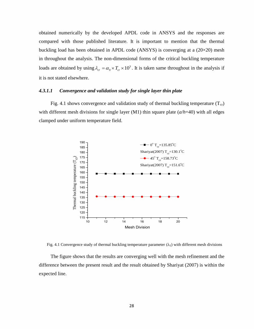
4.3.1.1 Convergence and validation study for single layer thin plate
Fig. 4.1 shows convergence and validation study of thermal buckling temperature (Tcr)
with different mesh divisions for single layer (M1) thin square plate (a/h=40) with all edges
clamped under uniform temperature field.
10 12 14 16 18 20
115
120
125
130
135
140
145
150
155
160
165
170
175
180
185
190
Ther
mal
buck
ling t
empe
ratu
re (
Tcr
)
Mesh Division
0o
Tcr
=135.85oC
Shariyat(2007) Tcr
=130.1oC
45o T
cr=158.73
oC
Shariyat(2007) Tcr
=151.6oC
Fig. 4.1 Convergence study of thermal buckling temperature parameter (λT) with different mesh divisions
The figure shows that the results are converging well with the mesh refinement and the
difference between the present result and the result obtained by Shariyat (2007) is within the
expected line.
29
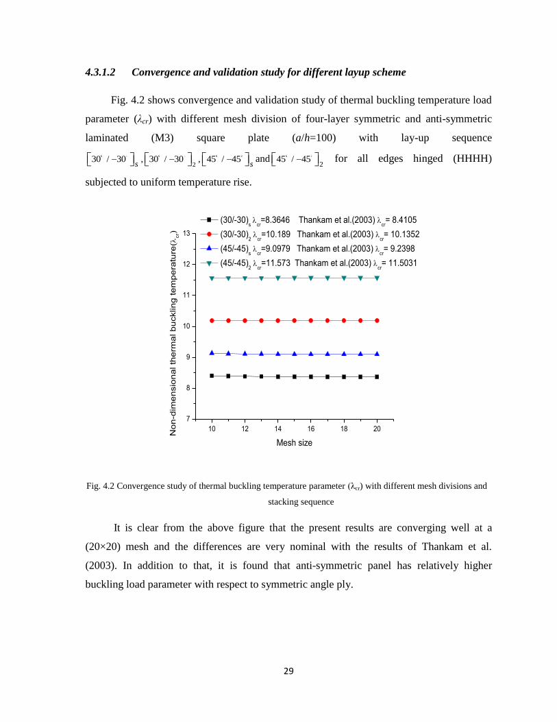
4.3.1.2 Convergence and validation study for different layup scheme
Fig. 4.2 shows convergence and validation study of thermal buckling temperature load
parameter (λcr) with different mesh division of four-layer symmetric and anti-symmetric
laminated (M3) square plate (a/h=100) with lay-up sequence
230 / 30 , 30 / 30 , 45 / 45
s s and
245 / 45 for all edges hinged (HHHH)
subjected to uniform temperature rise.
10 12 14 16 18 20
7
8
9
10
11
12
13
No
n-d
ime
nsio
na
l th
erm
al b
ucklin
g te
mp
era
ture
(cr)
Mesh size
(30/-30)s
cr=8.3646 Thankam et al.(2003)
cr= 8.4105
(30/-30)2
cr=10.189 Thankam et al.(2003)
cr= 10.1352
(45/-45)s
cr=9.0979 Thankam et al.(2003)
cr= 9.2398
(45/-45)2
cr=11.573 Thankam et al.(2003)
cr= 11.5031
Fig. 4.2 Convergence study of thermal buckling temperature parameter (λcr) with different mesh divisions and
stacking sequence
It is clear from the above figure that the present results are converging well at a
(20×20) mesh and the differences are very nominal with the results of Thankam et al.
(2003). In addition to that, it is found that anti-symmetric panel has relatively higher
buckling load parameter with respect to symmetric angle ply.
30
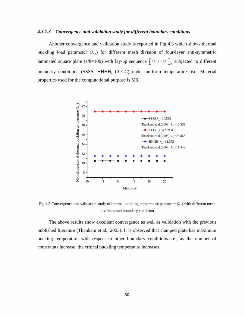
4.3.1.3 Convergence and validation study for different boundary conditions
Another convergence and validation study is reported in Fig 4.3 which shows thermal
buckling load parameter (λcr) for different mesh division of four-layer anti-symmetric
laminated square plate (a/h=100) with lay-up sequence 2
45 / 45 subjected to different
boundary conditions (SSSS, HHHH, CCCC) under uniform temperature rise. Material
properties used for the computational purpose is M3.
10 12 14 16 18 20
8
10
12
14
16
18
20
22
Non-d
imensi
onal
therm
al
buckli
ng t
em
pera
ture
(
cr)
Mesh size
SSSS cr=10.533
Thankam et.al.(2003) cr=10.569
CCCC cr=20.934
Thankam et.al.(2003) cr=20.863
HHHH cr=11.572
Thankam et.al.(2003) cr=11.548
Fig.4.3 Convergence and validation study of thermal buckling temperature parameter (λT) with different mesh
divisions and boundary condition
The above results show excellent convergence as well as validation with the previous
published literature (Thankam et al., 2003). It is observed that clamped plate has maximum
bucking temperature with respect to other boundary conditions i.e., as the number of
constraints increase, the critical buckling temperature increases.
31
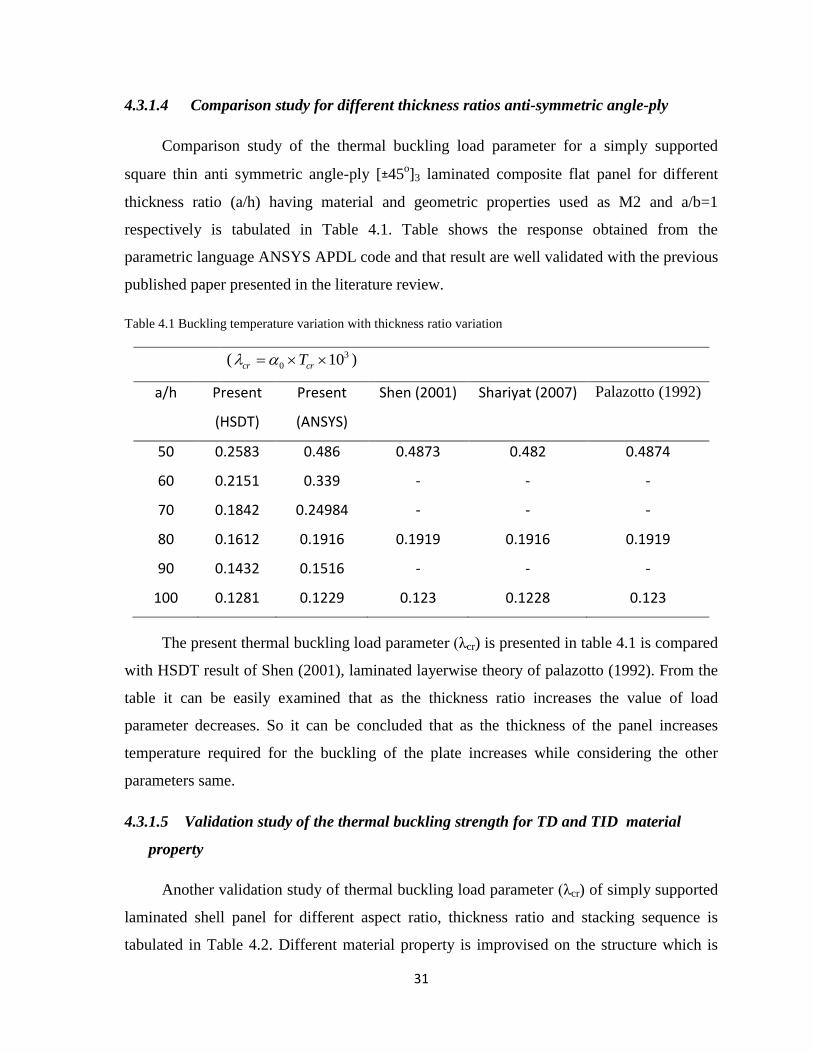
4.3.1.4 Comparison study for different thickness ratios anti-symmetric angle-ply
Comparison study of the thermal buckling load parameter for a simply supported
square thin anti symmetric angle-ply [±45o]3 laminated composite flat panel for different
thickness ratio (a/h) having material and geometric properties used as M2 and a/b=1
respectively is tabulated in Table 4.1. Table shows the response obtained from the
parametric language ANSYS APDL code and that result are well validated with the previous
published paper presented in the literature review.
Table 4.1 Buckling temperature variation with thickness ratio variation
( 3
0 10cr crT )
a/h Present
(HSDT)
Present
(ANSYS)
Shen (2001)
Shariyat (2007)
Palazotto (1992)
50 0.2583 0.486 0.4873 0.482 0.4874
60 0.2151 0.339 - - -
70 0.1842 0.24984 - - -
80 0.1612 0.1916 0.1919 0.1916 0.1919
90 0.1432 0.1516 - - -
100 0.1281 0.1229 0.123 0.1228 0.123
The present thermal buckling load parameter (λcr) is presented in table 4.1 is compared
with HSDT result of Shen (2001), laminated layerwise theory of palazotto (1992). From the
table it can be easily examined that as the thickness ratio increases the value of load
parameter decreases. So it can be concluded that as the thickness of the panel increases
temperature required for the buckling of the plate increases while considering the other
parameters same.
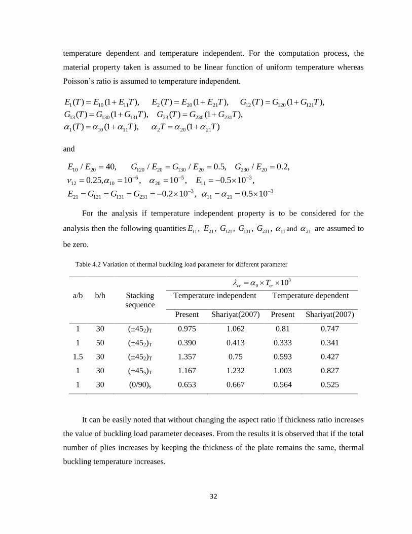
4.3.1.5 Validation study of the thermal buckling strength for TD and TID material
property
Another validation study of thermal buckling load parameter (λcr) of simply supported
laminated shell panel for different aspect ratio, thickness ratio and stacking sequence is
tabulated in Table 4.2. Different material property is improvised on the structure which is
32
temperature dependent and temperature independent. For the computation process, the
material property taken is assumed to be linear function of uniform temperature whereas
Poisson‘s ratio is assumed to temperature independent.
1 10 11 2 20 21 12 120 121
13 130 131 23 230 231
1 10 11 2 20 21
( ) (1 ), ( ) (1 ), ( ) (1 ),
( ) (1 ), ( ) (1 ),
( ) (1 ), (1 )
E T E E T E T E E T G T G G T
G T G G T G T G G T
T T T T
and
10 20 120 20 130 20 230 20
6 5 312 10 20 11
3 321 121 131 231 11 21
/ 40, / / 0.5, / 0.2,
0.25, 10 , 10 , 0.5 10 ,
0.2 10 , 0.5 10
E E G E G E G E
E
E G G G
For the analysis if temperature independent property is to be considered for the
analysis then the following quantities 11E , 21E , 121G , 131G , 231G , 11 and 21 are assumed to
be zero.
Table 4.2 Variation of thermal buckling load parameter for different parameter
3
0 10cr crT
a/b b/h Stacking
sequence
Temperature independent
Temperature dependent
Present Shariyat(2007)
Present Shariyat(2007)
1 30 (±452)T 0.975 1.062 0.81 0.747
1 50 (±452)T 0.390 0.413 0.333 0.341
1.5 30 (±452)T 1.357 0.75 0.593 0.427
1 30 (±455)T 1.167 1.232 1.003 0.827
1 30 (0/90)s 0.653 0.667 0.564 0.525
It can be easily noted that without changing the aspect ratio if thickness ratio increases
the value of buckling load parameter deceases. From the results it is observed that if the total
number of plies increases by keeping the thickness of the plate remains the same, thermal
buckling temperature increases.
33
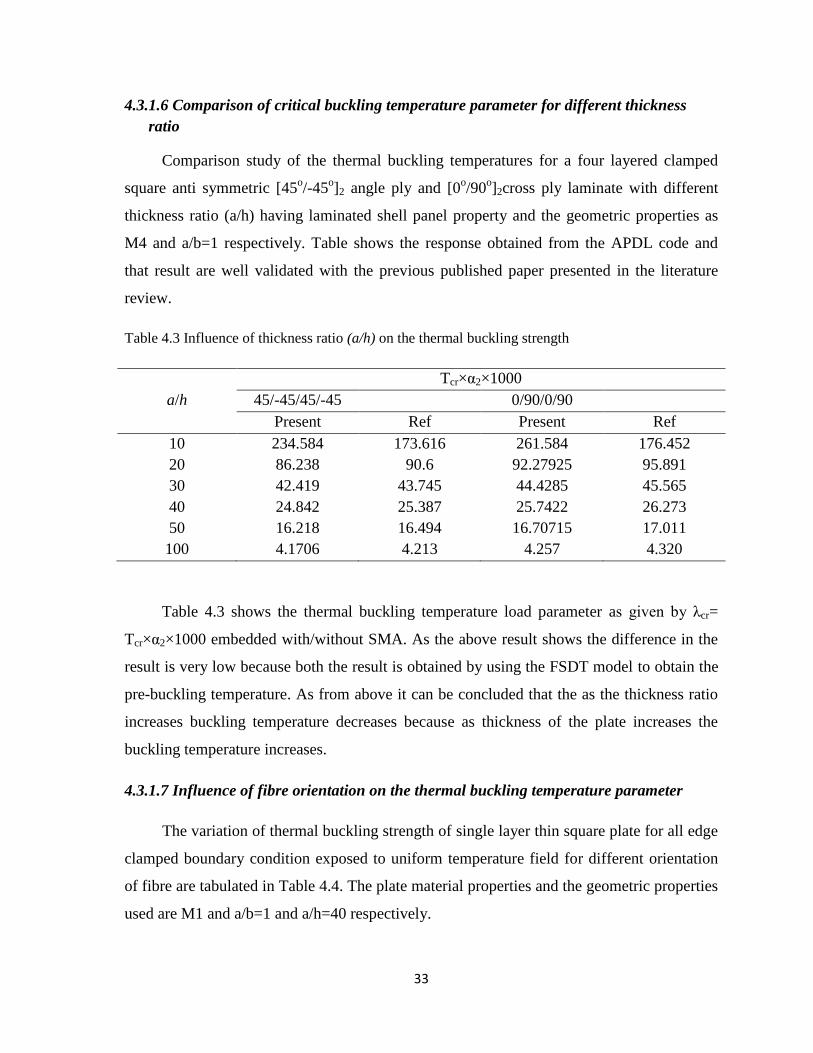
4.3.1.6 Comparison of critical buckling temperature parameter for different thickness
ratio
Comparison study of the thermal buckling temperatures for a four layered clamped
square anti symmetric [45o/-45
o]2 angle ply and [0
o/90
o]2cross ply laminate with different
thickness ratio (a/h) having laminated shell panel property and the geometric properties as
M4 and a/b=1 respectively. Table shows the response obtained from the APDL code and
that result are well validated with the previous published paper presented in the literature
review.
Table 4.3 Influence of thickness ratio (a/h) on the thermal buckling strength
Tcr×α2×1000
a/h 45/-45/45/-45 0/90/0/90
Present Ref Present Ref
10 234.584 173.616 261.584 176.452
20 86.238 90.6 92.27925 95.891
30 42.419 43.745 44.4285 45.565
40 24.842 25.387 25.7422 26.273
50 16.218 16.494 16.70715 17.011
100 4.1706 4.213 4.257 4.320
Table 4.3 shows the thermal buckling temperature load parameter as given by λcr=
Tcr×α2×1000 embedded with/without SMA. As the above result shows the difference in the
result is very low because both the result is obtained by using the FSDT model to obtain the
pre-buckling temperature. As from above it can be concluded that the as the thickness ratio
increases buckling temperature decreases because as thickness of the plate increases the
buckling temperature increases.
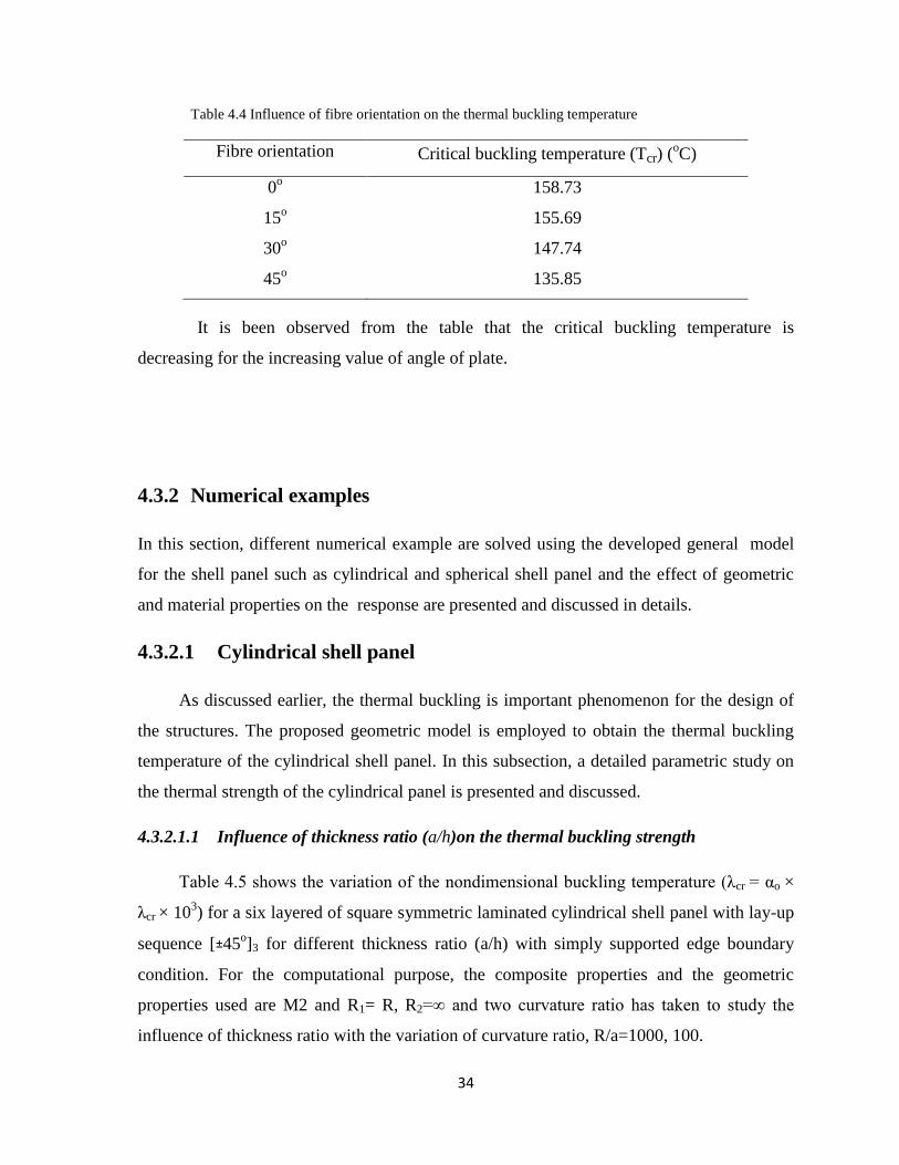
4.3.1.7 Influence of fibre orientation on the thermal buckling temperature parameter
The variation of thermal buckling strength of single layer thin square plate for all edge
clamped boundary condition exposed to uniform temperature field for different orientation
of fibre are tabulated in Table 4.4. The plate material properties and the geometric properties
used are M1 and a/b=1 and a/h=40 respectively.
34
Table 4.4 Influence of fibre orientation on the thermal buckling temperature
Fibre orientation Critical buckling temperature (Tcr) (oC)
0o 158.73
15o 155.69
30o 147.74
45o 135.85
It is been observed from the table that the critical buckling temperature is
decreasing for the increasing value of angle of plate.
4.3.2 Numerical examples
In this section, different numerical example are solved using the developed general model
for the shell panel such as cylindrical and spherical shell panel and the effect of geometric
and material properties on the response are presented and discussed in details.
4.3.2.1 Cylindrical shell panel
As discussed earlier, the thermal buckling is important phenomenon for the design of
the structures. The proposed geometric model is employed to obtain the thermal buckling
temperature of the cylindrical shell panel. In this subsection, a detailed parametric study on
the thermal strength of the cylindrical panel is presented and discussed.
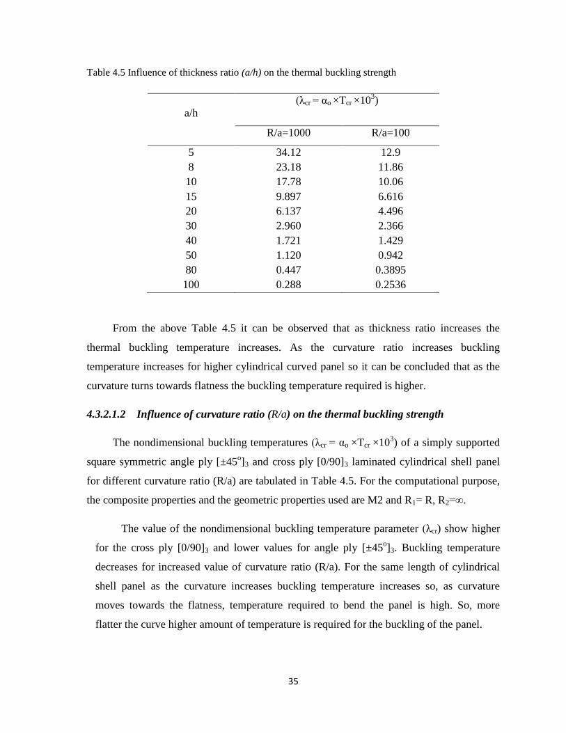
4.3.2.1.1 Influence of thickness ratio (a/h)on the thermal buckling strength
Table 4.5 shows the variation of the nondimensional buckling temperature (λcr = αo ×
λcr × 103) for a six layered of square symmetric laminated cylindrical shell panel with lay-up
sequence [±45o]3 for different thickness ratio (a/h) with simply supported edge boundary
condition. For the computational purpose, the composite properties and the geometric
properties used are M2 and R1= R, R2=∞ and two curvature ratio has taken to study the
influence of thickness ratio with the variation of curvature ratio, R/a=1000, 100.
35
Table 4.5 Influence of thickness ratio (a/h) on the thermal buckling strength
(λcr = αo ×Tcr ×103)
a/h
R/a=1000 R/a=100
5 34.12 12.9
8 23.18 11.86
10 17.78 10.06
15 9.897 6.616
20 6.137 4.496
30 2.960 2.366
40 1.721 1.429
50 1.120 0.942
80 0.447 0.3895
100 0.288 0.2536
From the above Table 4.5 it can be observed that as thickness ratio increases the
thermal buckling temperature increases. As the curvature ratio increases buckling
temperature increases for higher cylindrical curved panel so it can be concluded that as the
curvature turns towards flatness the buckling temperature required is higher.
4.3.2.1.2 Influence of curvature ratio (R/a) on the thermal buckling strength
The nondimensional buckling temperatures (λcr = αo ×Tcr ×103) of a simply supported
square symmetric angle ply [±45o]3 and cross ply [0/90]3 laminated cylindrical shell panel
for different curvature ratio (R/a) are tabulated in Table 4.5. For the computational purpose,
the composite properties and the geometric properties used are M2 and R1= R, R2=∞.
The value of the nondimensional buckling temperature parameter (λcr) show higher
for the cross ply [0/90]3 and lower values for angle ply [±45o]3. Buckling temperature
decreases for increased value of curvature ratio (R/a). For the same length of cylindrical
shell panel as the curvature increases buckling temperature increases so, as curvature
moves towards the flatness, temperature required to bend the panel is high. So, more
flatter the curve higher amount of temperature is required for the buckling of the panel.
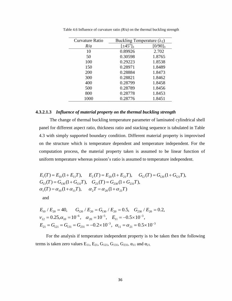
36
Table 4.6 Influence of curvature ratio (R/a) on the thermal buckling strength
Curvature Ratio Buckling Temperature (λT)
R/a [±45o]3 [0/90]3
10 0.89926 2.702
50 0.30598 1.8765
100 0.29223 1.8538
150 0.28971 1.8489
200 0.28884 1.8473
300 0.28821 1.8462
400 0.28799 1.8458
500 0.28789 1.8456
800 0.28778 1.8453
1000 0.28776 1.8451
4.3.2.1.3 Influence of material property on the thermal buckling strength
The change of thermal buckling temperature parameter of laminated cylindrical shell
panel for different aspect ratio, thickness ratio and stacking sequence is tabulated in Table
4.3 with simply supported boundary condition. Different material property is improvised
on the structure which is temperature dependent and temperature independent. For the
computation process, the material property taken is assumed to be linear function of
uniform temperature whereas poisson‘s ratio is assumed to temperature independent.
1 10 11 2 20 21 12 120 121
13 130 131 23 230 231
1 10 11 2 20 21
( ) (1 ), ( ) (1 ), ( ) (1 ),
( ) (1 ), ( ) (1 ),
( ) (1 ), (1 )
E T E E T E T E E T G T G G T
G T G G T G T G G T
T T T T
and
10 20 120 20 130 20 230 20
6 5 312 10 20 11
3 321 121 131 231 11 21
/ 40, / / 0.5, / 0.2,
0.25, 10 , 10 , 0.5 10 ,
0.2 10 , 0.5 10
E E G E G E G E
E
E G G G
For the analysis if temperature independent property is to be taken then the following
terms is taken zero values E11, E21, G121, G131, G231, α11 and α21.
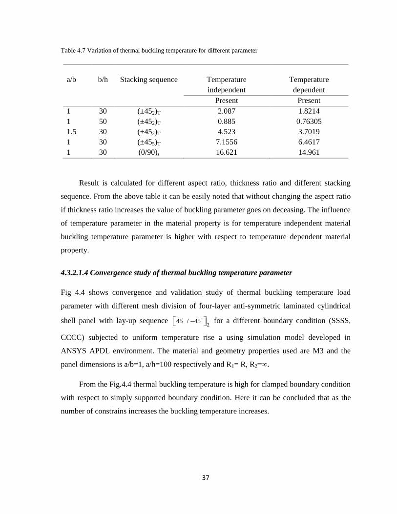
37
Table 4.7 Variation of thermal buckling temperature for different parameter
a/b b/h Stacking sequence Temperature
independent
Temperature
dependent
Present Present
1 30 (±452)T 2.087 1.8214
1 50 (±452)T 0.885 0.76305
1.5 30 (±452)T 4.523 3.7019
1 30 (±455)T 7.1556 6.4617
1 30 (0/90)s 16.621 14.961
Result is calculated for different aspect ratio, thickness ratio and different stacking
sequence. From the above table it can be easily noted that without changing the aspect ratio
if thickness ratio increases the value of buckling parameter goes on deceasing. The influence
of temperature parameter in the material property is for temperature independent material
buckling temperature parameter is higher with respect to temperature dependent material
property.
4.3.2.1.4 Convergence study of thermal buckling temperature parameter
Fig 4.4 shows convergence and validation study of thermal buckling temperature load
parameter with different mesh division of four-layer anti-symmetric laminated cylindrical
shell panel with lay-up sequence 2
45 / 45 for a different boundary condition (SSSS,
CCCC) subjected to uniform temperature rise a using simulation model developed in
ANSYS APDL environment. The material and geometry properties used are M3 and the
panel dimensions is a/b=1, a/h=100 respectively and R1= R, R2=∞.
From the Fig.4.4 thermal buckling temperature is high for clamped boundary condition
with respect to simply supported boundary condition. Here it can be concluded that as the
number of constrains increases the buckling temperature increases.
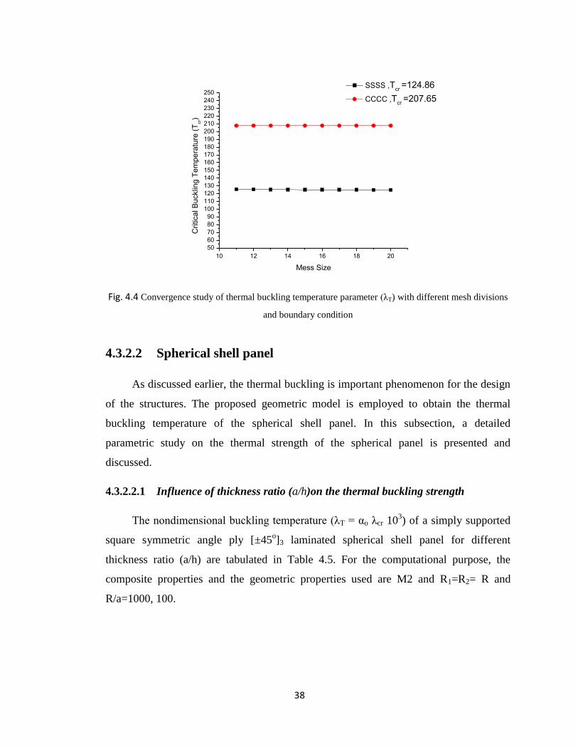
38
10 12 14 16 18 20
50
60
70
80
90
100
110
120
130
140
150
160
170
180
190
200
210
220
230
240
250
Cri
tica
l B
ucklin
g T
em
pe
ratu
re (
Tcr)
Mess Size
SSSS ,Tcr
=124.86
CCCC ,Tcr
=207.65
Fig. 4.4 Convergence study of thermal buckling temperature parameter (λT) with different mesh divisions
and boundary condition
4.3.2.2 Spherical shell panel
As discussed earlier, the thermal buckling is important phenomenon for the design
of the structures. The proposed geometric model is employed to obtain the thermal
buckling temperature of the spherical shell panel. In this subsection, a detailed
parametric study on the thermal strength of the spherical panel is presented and
discussed.
4.3.2.2.1 Influence of thickness ratio (a/h)on the thermal buckling strength
The nondimensional buckling temperature (λT = αo λcr 103) of a simply supported
square symmetric angle ply [±45o]3 laminated spherical shell panel for different
thickness ratio (a/h) are tabulated in Table 4.5. For the computational purpose, the
composite properties and the geometric properties used are M2 and R1=R2= R and
R/a=1000, 100.
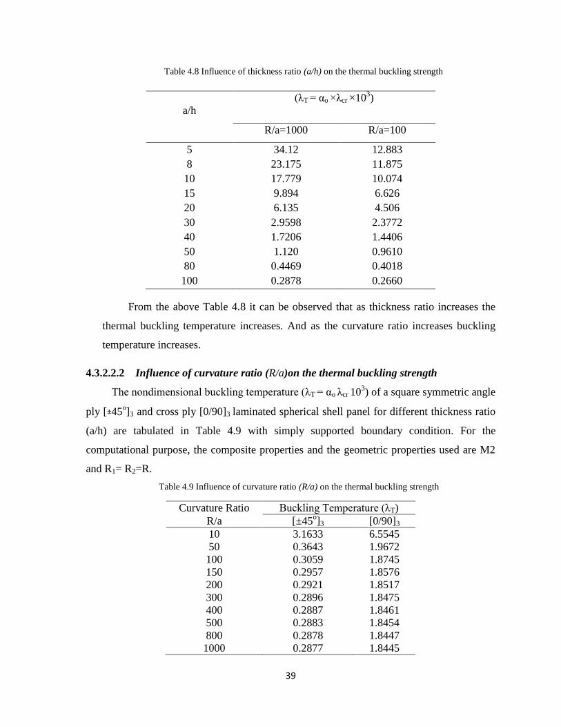
39
Table 4.8 Influence of thickness ratio (a/h) on the thermal buckling strength
(λT = αo ×λcr ×103)
a/h
R/a=1000 R/a=100
5 34.12 12.883
8 23.175 11.875
10 17.779 10.074
15 9.894 6.626
20 6.135 4.506
30 2.9598 2.3772
40 1.7206 1.4406
50 1.120 0.9610
80 0.4469 0.4018
100 0.2878 0.2660
From the above Table 4.8 it can be observed that as thickness ratio increases the
thermal buckling temperature increases. And as the curvature ratio increases buckling
temperature increases.
4.3.2.2.2 Influence of curvature ratio (R/a)on the thermal buckling strength
The nondimensional buckling temperature (λT = αo λcr 103) of a square symmetric angle
ply [±45o]3 and cross ply [0/90]3 laminated spherical shell panel for different thickness ratio
(a/h) are tabulated in Table 4.9 with simply supported boundary condition. For the
computational purpose, the composite properties and the geometric properties used are M2
and R1= R2=R.
Table 4.9 Influence of curvature ratio (R/a) on the thermal buckling strength
Curvature Ratio Buckling Temperature (λT)
R/a [±45o]3 [0/90]3
10 3.1633 6.5545
50 0.3643 1.9672
100 0.3059 1.8745
150 0.2957 1.8576
200 0.2921 1.8517
300 0.2896 1.8475
400 0.2887 1.8461
500 0.2883 1.8454
800 0.2878 1.8447
1000 0.2877 1.8445
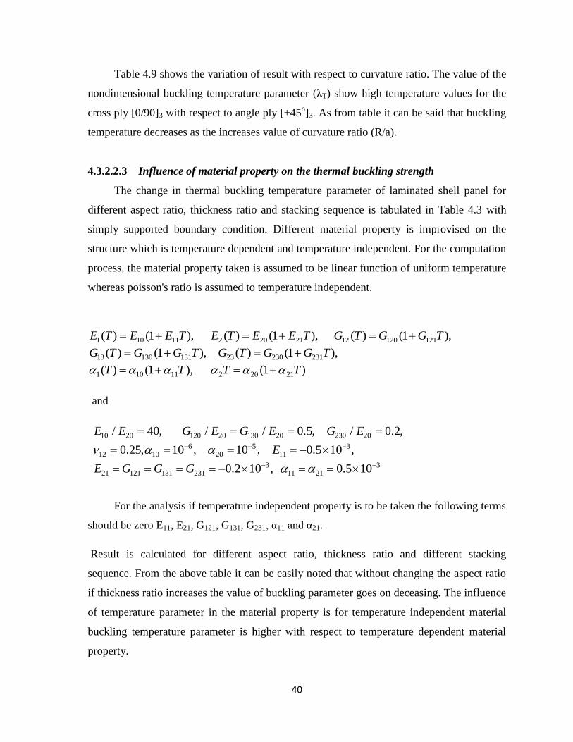
40
Table 4.9 shows the variation of result with respect to curvature ratio. The value of the
nondimensional buckling temperature parameter (λT) show high temperature values for the
cross ply [0/90]3 with respect to angle ply [±45o]3. As from table it can be said that buckling
temperature decreases as the increases value of curvature ratio (R/a).
4.3.2.2.3 Influence of material property on the thermal buckling strength
The change in thermal buckling temperature parameter of laminated shell panel for
different aspect ratio, thickness ratio and stacking sequence is tabulated in Table 4.3 with
simply supported boundary condition. Different material property is improvised on the
structure which is temperature dependent and temperature independent. For the computation
process, the material property taken is assumed to be linear function of uniform temperature
whereas poisson's ratio is assumed to temperature independent.
1 10 11 2 20 21 12 120 121
13 130 131 23 230 231
1 10 11 2 20 21
( ) (1 ), ( ) (1 ), ( ) (1 ),
( ) (1 ), ( ) (1 ),
( ) (1 ), (1 )
E T E E T E T E E T G T G G T
G T G G T G T G G T
T T T T
and
10 20 120 20 130 20 230 20
6 5 312 10 20 11
3 321 121 131 231 11 21
/ 40, / / 0.5, / 0.2,
0.25, 10 , 10 , 0.5 10 ,
0.2 10 , 0.5 10
E E G E G E G E
E
E G G G
For the analysis if temperature independent property is to be taken the following terms
should be zero E11, E21, G121, G131, G231, α11 and α21.
Result is calculated for different aspect ratio, thickness ratio and different stacking
sequence. From the above table it can be easily noted that without changing the aspect ratio
if thickness ratio increases the value of buckling parameter goes on deceasing. The influence
of temperature parameter in the material property is for temperature independent material
buckling temperature parameter is higher with respect to temperature dependent material
property.
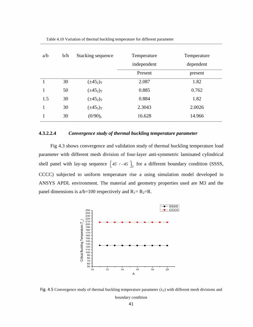
41
Table 4.10 Variation of thermal buckling temperature for different parameter
a/b b/h Stacking sequence Temperature
independent
Temperature
dependent
Present present
1 30 (±452)T 2.087 1.82
1 50 (±452)T 0.885 0.762
1.5 30 (±452)T 0.884 1.82
1 30 (±455)T 2.3043 2.0026
1 30 (0/90)s 16.628 14.966
4.3.2.2.4 Convergence study of thermal buckling temperature parameter
Fig 4.3 shows convergence and validation study of thermal buckling temperature load
parameter with different mesh division of four-layer anti-symmetric laminated cylindrical
shell panel with lay-up sequence 2
45 / 45 for a different boundary condition (SSSS,
CCCC) subjected to uniform temperature rise a using simulation model developed in
ANSYS APDL environment. The material and geometry properties used are M3 and the
panel dimensions is a/h=100 respectively and R1= R2=R.
10 12 14 16 18 20
50
60
70
80
90
100
110
120
130
140
150
160
170
180
190
200
210
220
230
240
250
Crit
ical
Buc
klin
g T
empe
ratu
re (
Tcr)
A
SSSS
CCCC
Fig. 4.5 Convergence study of thermal buckling temperature parameter (λT) with different mesh divisions and
boundary condition
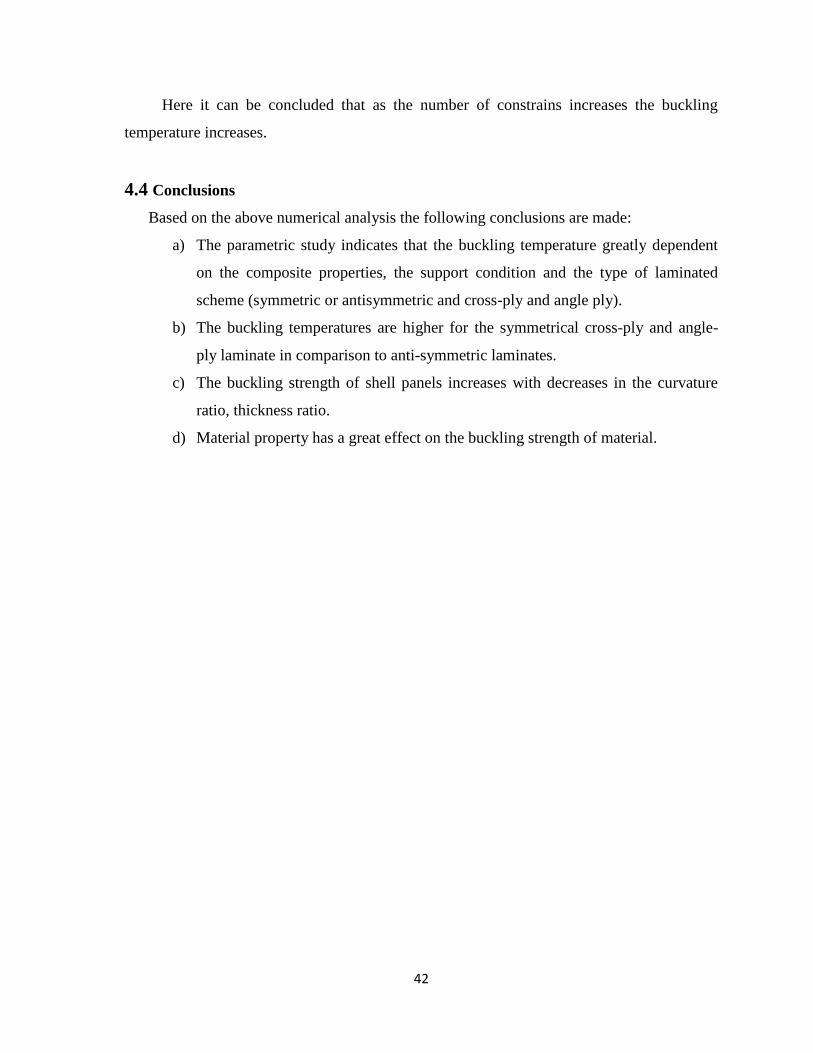
42
Here it can be concluded that as the number of constrains increases the buckling
temperature increases.
4.4 Conclusions
Based on the above numerical analysis the following conclusions are made:
a) The parametric study indicates that the buckling temperature greatly dependent
on the composite properties, the support condition and the type of laminated
scheme (symmetric or antisymmetric and cross-ply and angle ply).
b) The buckling temperatures are higher for the symmetrical cross-ply and angle-
ply laminate in comparison to anti-symmetric laminates.
c) The buckling strength of shell panels increases with decreases in the curvature
ratio, thickness ratio.
d) Material property has a great effect on the buckling strength of material.
43
CHAPTER 5
THERMAL BUCKLING ANALYSIS OF LAMINATED SHELL
PANELS EMBEDDED WITH SMA FIBRES
5.1 Introduction
In this chapter, the buckling strength of laminated composite shell embedded with
SMA fibres exposed to thermal environment have been studied using the proposed nonlinear
model. The geometrical nonlinearity in Green-Lagrangian sense and material nonlinearity in
the SMA are incorporated in the model through the strain displacement relations and the
constitutive relations are discussed in Chapter 3. It is well known from the earlier discussion
that, the excess thermal deformation and the induced thermal stress change the structural
geometry, which considerably affects the performance of the laminated structures. Since the
laminated structure are very flexible in nature, the induced thermal deformations and stress
play an important role in their practical design. In order to suppress these deformations and
increases the life of the laminated structures against thermal loading passive treatments were
used earlier, but they suffer from weight penalty. In order to increases these performance
smart materials are suitable alternative. In recent years, many studies have been carried out
by different researchers to improve the structural performances against thermal loading
using SMA fibres as a smart material. In this analysis as effort has been made to predict the
enhancement of the thermal buckling strength of the plate embedded with SMA fibres
considering the excess thermal deformation of the shell panel by taking the geometric matrix
and geometric nonlinearity in Green-Lagrange sense based on the HSDT.
The purpose of this chapter is to derive the governing system equation of laminated
composite plate embedded with SMA fibres by taking the geometric nonlinearity in Green-
Lagrange sense and the material nonlinearity in SMA through a marching technique. The
solution techniques are outlined for the first time derived governing system equations. A
number of numerical examples have been solved for plate and discussed. The efficiency and
necessity of the present nonlinear model has been shown by comparing the result with those
available in the literature.
44
5.2 Governing System Equation and solution
The governing equations of motion for thermal buckling composite plate embedded
with SMA fibres are obtained using Eq. (3.12). These are rewritten elaborately as follows:
0cr GL rK K K
(5.1)
where, is the global displacement vector, L
K , r
K
and GK are the global linear
stiffness matrix, geometric stiffness matrix of SMA due to recovery stress and global
geometric matrix due to the uniform temperature rise, respectively.
The matrix equation (5.1) is solved using direct iterative method following the same
steps as discussed in Chapter 4.
5.3 Result and Discussion
A computer code has been developed in MATLAB R2010a for laminated composite
plate embedded with SMA fibres by taking the geometric nonlinearity in Green-Lagrange
sense and the material nonlinearity in SMA due to the temperature change. In the present
study a uniform temperature variation has been taken for the composite panel through
thickness. The composite matrix properties are taken as a function of temperature. The SMA
properties are evaluated by using marching technique with small increment in temperature
whereas reference temperature assumed to be 24oC. A validation and convergence test has
been done to show the efficiency of the present nonlinear model. The effect of different
parameters on the buckling temperature have been obtained in detail and discussed. The
stacking sequence, geometrical and the material properties are taken same as the Park et al.
(2004) for the comparison and convergence purpose. The mechanical and thermal
properties matrix and SMA fibres are presented in Table 5.1 and are used for the analysis
unless started otherwise.
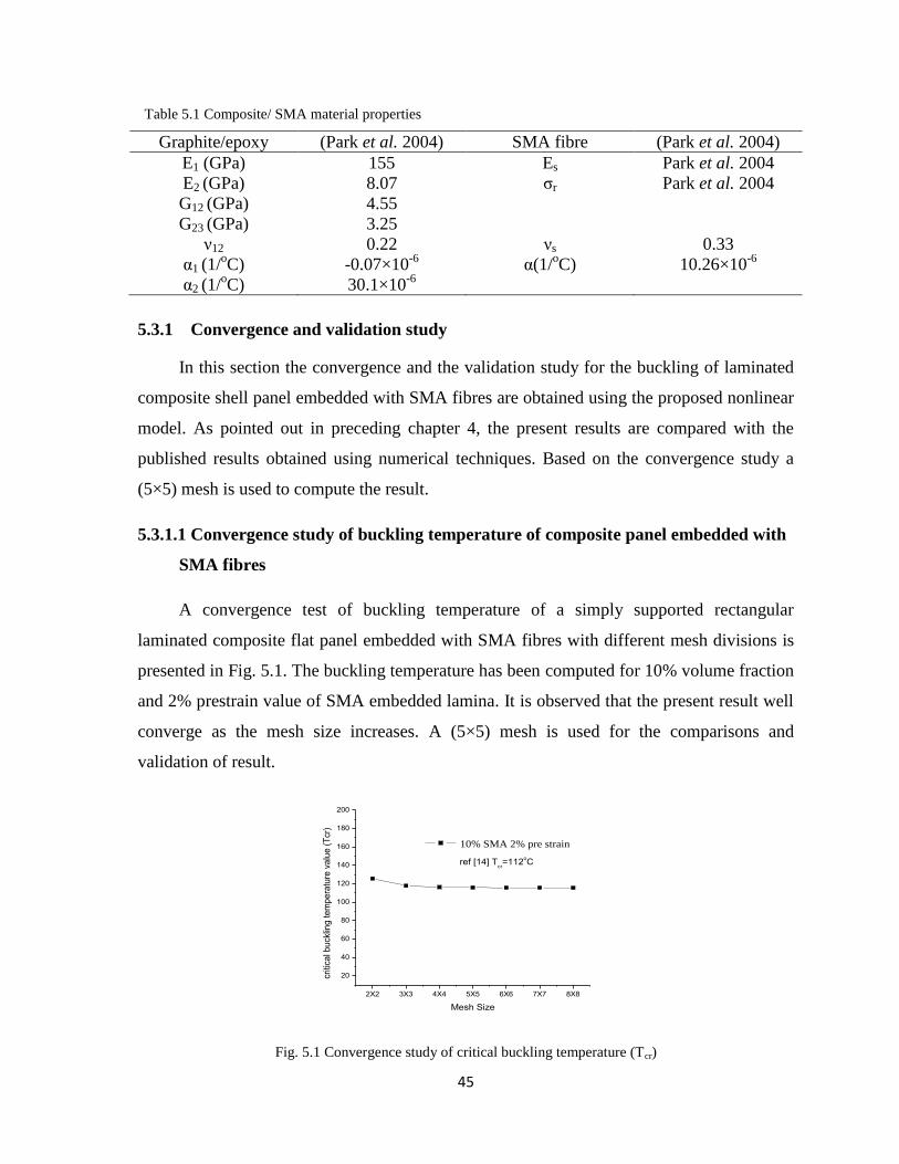
45
Table 5.1 Composite/ SMA material properties
Graphite/epoxy (Park et al. 2004) SMA fibre (Park et al. 2004)
E1 (GPa) 155 Es Park et al. 2004
E2 (GPa) 8.07 σr Park et al. 2004
G12 (GPa) 4.55
G23 (GPa) 3.25
ν12 0.22 νs 0.33
α1 (1/oC) -0.07×10
-6 α(1/
oC) 10.26×10
-6
α2 (1/oC) 30.1×10
-6
5.3.1 Convergence and validation study
In this section the convergence and the validation study for the buckling of laminated
composite shell panel embedded with SMA fibres are obtained using the proposed nonlinear
model. As pointed out in preceding chapter 4, the present results are compared with the
published results obtained using numerical techniques. Based on the convergence study a
(5×5) mesh is used to compute the result.
5.3.1.1 Convergence study of buckling temperature of composite panel embedded with
SMA fibres
A convergence test of buckling temperature of a simply supported rectangular
laminated composite flat panel embedded with SMA fibres with different mesh divisions is
presented in Fig. 5.1. The buckling temperature has been computed for 10% volume fraction
and 2% prestrain value of SMA embedded lamina. It is observed that the present result well
converge as the mesh size increases. A (5×5) mesh is used for the comparisons and
validation of result.
2X2 3X3 4X4 5X5 6X6 7X7 8X8
20
40
60
80
100
120
140
160
180
200
10% SMA 2% pre strain
criti
cal b
uck
ling
te
mp
era
ture
va
lue
(T
cr)
Mesh Size
ref [14] Tcr=112
oC
Fig. 5.1 Convergence study of critical buckling temperature (Tcr)

46
5.3.1.2 Influence of thickness ratio (a/h) on the buckling temperature parameter
Influence of thickness ratio (a/h) on the nondimensional buckling temperature of a
square symmetric angle-ply (0/±45/90)S and (0/±90/0)S laminated composite plate embedded
with SMA fibre is depicted in table 6.1 subjected simply supported boundary condition. The
SMA is 2% prestrain. It is can be concluded that the buckling temperature decreases as
thickness ratio increases.
Table 5.1 Influence of thickness ratio on buckling temperature load parameter
a/h (0/45/-45/90)s (0/90/90/0)s
SSSS CCCC SSSS CCCC
10 141.3509 192.5468 7.7964 11.1488
20 96.4102 180.3748 4.8130 11.2242
40 53.053 120.0852 2.5690 7.3339
50 43.0139 100.9401 2.0755 6.1458
80 27.3406 67.7467 1.144 4.1113
100 21.9784 55.4783 1.0556 3.3607
5.4 Conclusion
Thermal buckling strength of curved laminated composite shell panel embedded with SMA
fibres has been studied using the proposed linear model. The geometrical nonlinearity is
modelled in Green-Lagrange sense incorporating all the higher order terms arising in the
mathematical formulation in the framework of HSDT. The material nonlinearity is
introduced for the SMA fibres due to the temperature increment through a marching
technique. The composite material properties are assumed to be temperature dependent
along the SMA. Influences of various geometrical parameters, the support condition have
been studied.
Based on the numerical results following conclusion drawn:
a) The buckling temperature decreases with the increases in thickness ratio.
b) For the clamped boundary condition, buckling load parameter retains higher values.
47
CHAPTER 6
CLOSURES
6.1 Concluding Remarks
In this present work, the thermal buckling behaviour of composite shell panel embedded
with and without SMA fibers are examined. A general mathematical model based on the
HSDT mid-plane kinematics is considered to obtain the true responses of composite shell
panels. The geometric instability is considered through the nonlinear Green-Lagrange strain
displacement relations to account the excess thermal deformation occurs during the
buckling. A suitable finite element model is proposed and implemented to solve the present
developed model. A detailed parametric study has been carried out by solving various
numerical examples of laminated composite shell panel of different geometries. The more
specific conclusions as a result of the present investigation are stated below:
In the present model, all the higher order terms are retained in the mathematical
formulation for more accurate prediction of the structural behaviour. It is important to
mention that, the Green-Lagrange type strain displacement relation is considered to
take into account the geometrical nonlinearity arising in the curved panel due to excess
deformation for evaluation of geometric stiffness matrix in buckling analysis. It is
concluded that the geometric nonlinearity modelled in von-Karman sense based on the
FSDT and/or the HSDT is unrealistic in nature for the structures having severe
geometric alteration.
A linear finite element is proposed and implemented for the discretisation of the shell
panel model by using a nine noded isoparametric Lagrangian element having nine
degrees of freedom per node. The governing system equations of buckling are derived
and solved to obtain the desired responses.
Convergence study is performed by refining the mesh density. The comparison study
for different cases indicates the necessity and requirement of the present mathematical
model for an accurate prediction of the structural behaviour.
The thermal buckling strength of laminated composite cylindrical, spherical and flat
panel has been examined by taking the uniform temperature field throughout the
48
thickness. The non-dimensional critical buckling load parameters are obtained by
solving the linear eigenvalue problem. Effects of the thickness ratio, the curvature
ratio, the lay-up scheme and the support condition are studied in details.
The non-dimensional critical buckling temperature parameter of angle-ply is higher
than the cross-ply laminations.
The non-dimensional buckling load/parameter increases with the increase in number
of layers and the thickness ratios but it is important to mention that in some of the
cases the responses are following a reverse trend for the small strain and large
deformations. The responses are decreasing with the increase in curvature ratio and
mixed type of behaviour is observed for support conditions and lay-up schemes.
The SMA embedded composite shell panels are having higher buckling temperature in
comparison to the composite shell panel without SMA fibers. Effect of the thickness
ratio is studied in details along with the effect of stacking sequence.
6.2 Significant Contribution of the Thesis
The contributions of the present research work are as follows:
A general mathematical model of curved panel has been developed in the framework
of the HSDT mid-plane kinematics by taking all the higher order terms in the
mathematical formulation for more accurate prediction of thermal buckling behaviour
of laminated composite panels.
A finite element method is proposed and implemented for the discretisation of the
shell panel model by using a nine noded isoparametric Lagrangian element with nine
degrees of freedom per node.
In buckling case, Green-Lagrange type strain displacement relation is considered to
account the geometrical nonlinearity arising in the curved panel due to excess thermal
deformation for evaluation of geometry stiffness matrix.
A computer code is developed in MATLAB environment based on the prosed
mathematical formulation and finite element steps.
Further, the panel model has been developed in the commercial FE software ANSYS
by using APDL code. An eight noded isoparametric serendipity shell element
(SHELL281) is employed to discretise the simulation model.
49
Different numerical examples have been considered to show the efficacy of the
developed mathematical and simulation model. The convergence and comparison
study for buckling behaviour of laminated panel is presented.
The effects of various panel geometries (spherical, cylindrical and flat) and other
geometrical parameters (thickness ratios, curvature ratios, aspect ratios, lamination
schemes and support conditions) on buckling responses are studied.
Thermal Buckling strength of the laminated composite spherical, cylindrical and flat
panel is obtained by taking the uniform temperature throughout the thickness. The
temperature dependent and independent composite material properties with and
without SMA are taken for the present analysis.
Finally, it is understood from the previous discussions that the developed general
mathematical panel model in the framework of the HSDT would be useful for more accurate
analysis of laminated composite structures exposed to excess thermal deformations. It is
important to mention that the geometry matrix associated in the buckling has been taken in
Green-Lagrange sense for the analysis. On the other hand, it is observed that the present
developed FE model in ANSYS environment is also capable to solve any buckling problem
easily and with less computational time. And hence, the present analysis would be useful for
practical design of the structure.
6.3 Future Scope of the Research
The present study has been done by using the linear mathematical model which can be
extended for nonlinear analysis of laminated composite.
The present study can be extended to investigate the nonlinear thermo-mechanical
post-buckling behavior of laminated composite structures by taking temperature
dependent material properties based on nonlinear mathematical model.
An experimental study on buckling of laminated composite panels will give better
understanding about the present developed numerical model.

50
By extending the present model, a nonlinear mathematical model can be developed to
study the behaviour of laminated composite and sandwich structures in thermal and/or
hygro-thermal environment.
It will be interesting to study the flutter characteristics considering the aerodynamic
and acoustic loading that arises frequently in the practical cases.
51
REFERENCES
Abediokhchi J., Kouchakzadeh M. A., and Shakouri M. (2013), Buckling Analysis of
Cross-Ply Laminated Conical Panels Using Generalized Differential Quadrature (GDQ)
Method, Composite. Part B Eng., Vol. 55, pp. 440–446.
Bedon C. and Amadio C. (2012), Buckling of Flat Laminated Glass Panels Under In-
Plane Compression or Shear, Engineering Structure, Vol. 36, pp. 185–197.
Burton D.S., Gao X. and Brinson L.C. (2006), Finite Element Simulation of a Self-
Healing Shape Memory Alloy Composite, Mechanics of Materials, Vol. 38, No. 5-6, pp.
525-537.
Chang J. S. and Leu S.Y. (1991), Thermal Buckling Analysis of Antisymmetric Angle-
Ply Laminates Based on a Higher-Order Displacement Field, Compos. Sci. And Tech.,
Vol. 41, pp. 109-128.
Chen, L. W., and Chen, L. Y. (1991), Thermal Post-Buckling Behaviour of Laminated
Composite Plates With Temperature –Dependent Properties. Composite Structures;
Vol.19;267-283.
Chen, L.W. and Chen, L.Y. (1991), Thermal Postbuckling Behaviors of Laminated
Composite Plates with Temperature-Dependent Property, Composite Structures, Vol.19
No.3, pp. 267-283.
Cook R. D., Malkus D. S., Plesha M. E. (2001), Concepts and Applications of Finite
Element Analysis, John Willy and Sons Pte. Ltd., Singapore.
Fazzolari F. A., Banerjee J. R., and Boscolo M. (2013), Buckling of Composite Plate
Assemblies using Higher Order Shear Deformation Theory—An Exact Method of
Solution, Thin-Walled Structure, Vol. 71, pp. 18–34.
Ganilova O.A. and Cartmell M.P. (2010), An Analytical Model for the Vibration of a
Composite Plate Containing an Embedded Periodic Shape Memory Alloy Structure,
Composite Structures, Vol. 92, No. 1, pp. 39-47.
Hartl D.J. and Lagoudas D. C. (2007), Aerospace Application of Shape Memory Alloys,
Proceeding of ImechE Journal of Aerospace Engineering, Vol. 221 No. 4, pp. 2015-
2023.
Jameel A. N., Sadiq I. A. and Nsaif H. I. (2012), Buckling Analysis of Composite Plates
under Thermal and Mechanical Loading, Journal of Engineering, Vol. 18, Pp. 1365–
1390.
52
Khalili S. M. R., Abbaspour P., and Fard K M. (2013), Buckling of Non-Ideal Simply
Supported Laminated Plate on Pasternak Foundation, Applied Mathematics and
Computation, Vol. 219, No. 12, pp. 6420–6430.
Khdeir A. A. and Librescu L. (1988), Analysis of Symmetric Cross-Ply Laminated
Elastic Plates Using a Higher-Order Theory: Part II—Buckling And Free Vibration,
Composite Structure, Vol. 9, No. 4, pp. 259–277.
Kheirikhah M. M., Khalili S. M. R., and Malekzadeh Fard K. (2012), Biaxial Buckling
Analysis of Soft-Core Composite Sandwich Plates Using Improved High-Order Theory,
European Journal Of Mechanics- A/Solids, Vol. 31, No. 1, pp. 54–66.
Komur M. A., Sen F., Ataş A., and Arslan N. (2010), Buckling Analysis of Laminated
Composite Plates with an Elliptical/Circular Cutout Using FEM, Advanced Engineering
Software, Vol. 41, No. 2, pp. 161–164.
Kumar C. N. and Singh B. N. (2009), Thermal Buckling and Post-Buckling of
Laminated Composite Plates with SMA Fibres using Layerwise Theory, International
Journal for Computational Methods in Engineering Science and Mechanics, Vol. 10,
No. 6, pp. 423–429.
Lee H. J., Lee J.J. and Huh J. S. (1999) A Simulation Study on the Thermal Buckling
Behaviour of Laminated Composite Shells Embedded with Shape Memory Alloy (SMA)
Wire, Composite Structure, Vol.47,No.1-4, pp. 463-469.
Lee J. (1997), Thermally-Induced Buckling of Laminated Composites by a Layerwise
Theory, Comput. & Struct., Vol. 65, No. 6, pp. 917-922.
Loughlan J., Thompson S.P. and Smith H. (2002), Buckling Control Using Embedded
Shape Memory Actuators and the Utilization of Smart Technology in Future Aerospace
Platforms, Vol. 58, No. 3, pp. 319-347.
Loughlan J., Tompson S.P. and Smith H. (2002), Buckling Control Using Embedded
Shape Memory Actuator and the Utilisation of Smart Technology in Future Aerospace
Platform , Composite Structures, Vol. 58, No. 3, pp. 319-334.
Matsunaga H. (2005) Thermal Buckling of Cross-Ply Laminated Composite and
Sandwich Pale According to a Global Higher Order Deformation Theory, Composite
Structures, Vol.68, No.4, pp. 439-454.
Nali P., Carrera E., and Lecca S. (2011), Assessments of Refined Theories for Buckling
Analysis of Laminated Plates, Composite Structure, Vol. 93, No. 2, pp. 456–464.
53
Naseer S.N.,Chori J.Y., Wei G.G. and Isascs J.B. (2005), Very High Strain-Rate
Response of a Ni-Ti Shape Memory Alloy, Mechanics of Materials, Vol.37, No. 2-3 pp.
287-298.
Nath Y. and Shukla, K.K. (2001), Post-Buckling of Angle-Ply Laminated Plate Under
Thermal Loading, Communication in Nonlinear Science and Numerical Simulation, Vol.
6, No. 1, pp. 1-16.
Ovesy H. R., Ghannadpour S. A. M. and Sherafat M. H. (2009), Buckling Analysis of
Laminated Composite Plates Using Higher Order Semi—Analytical Finite Strip Method,
Applied Composite Material, Vol.17, pp 69–80.
Palazotto A.N., Dennis S.T. (1991), Nonlinear analysis of shell structures, American
Institute of Aeronautics and Astronautics, USA.
Panda S.K. and Singh B.N. (2013), Nonlinear Finite Element Analysis of Thermal Post-
Buckling Vibration of Laminated Composite Shell Panel Embedded with SMA Fibre,
Aerospace Science and Technology, Vol.29, No. 1, pp. 47-57.
Panda S.K. and Singh B.N. (2013), Post-Buckling Analysis of Laminated Composite
Doubly Curved Panel Embedded with SMA Fibres Subjected to Thermal Environment
Vol.20, No. 10, pp. 842-853.
Park J.S., Kim J.H. and Moon S.H. (2005), Thermal Post-Buckling and Flutter
Characteristics of Composite Plates Embedded with Shape Memory Alloy Fibres,
Composites Part B: Engineering, Vol. 36, No. 8, pp. 627–636.
Poon C.K., Zhou L.M., and Yam L.H. (2004), Size Effect on the Optimum Actuation
Condition for SMA-Composites, Composite Structures, Vol. 66, No. 1-4, pp. 503-511.
Qiao T., Liu L., Liu Y. and Leng J. (2013), Post Buckling Analysis of the Shape
Memory Polymer Composite Laminate Bonded with Alloy Film, Composites Part B:
Engineering, Vol. 53, pp. 218-225
Rahman M.A., Qui J. and Tani J. (2001), Buckling and Postbuckling of the Superelastic
SMA Columns, International Journal of Solid and Structures, Vol. 38, No. 50-51, pp.
9253-9265.
Reddy, J. N. (2003), Mechanics of Laminated Composite Plates and Shells CRC Press
Taylor and Francis, United State.
Sahin, O.S. (2005), Thermal Buckling of Hybrid Angle-Ply Laminated Composite Plates
With Hole, Composite Science and Technology, Vol.65, No. (11-12), Pp. 1780-1790.
54
Seifi R., Khoda-yari N., and Hosseini H. (2012), Study of Critical Buckling Loads and
Modes of Cross-Ply Laminated Annular Plates, Composite Part B Engineering, Vol. 43,
No. 2, pp. 422–430.
Shadmehri F., Hoa S. V., and Hojjati M. (2012), Buckling of Conical Composite Shells,
Composite Structures, Vol. 94, No. 2, pp. 787–792.
Shariyat, M. (2007), Thermal Buckling Analysis of Rectangular Composite Plates With
Temperature-Dependent Properties Based on a Layer Wise Theory, Thin Walled
Structures, Vol.45, No. 4, Pp. 439-452.
Shen, H. S. (1997), Thermal Post-Buckling Analysis of Imperfect Laminated Plates
Using a Higher-Order Shear Deformation Theory, International Journal of Non-Linear
Mechanics, Vol.32, No.6, pp1035-1050.
Shen, H.S. (2001), Thermal Postbuckling Behavior of Imperfect Shear Deformable
Laminated Plates with Temperature-Dependent Properties, Computer Methods in
Applied Mechanics and Engineering, Vol.190, No. 40-41 pp5377–5390.
Shen, H.S. (2001), Thermal Postbuckling Behaviour of Imperfect Shear Deformable
Laminated Plate with Temperature Dependent Properties, Computer Methods Applied
Mechanics and Engineering, Vol.190, No. 40-41, pp.5377-5390.
Shiau, L. C. A, Kuo, S. Y. and Chen, C. Y. (2010), Thermal Buckling Behaviour of
Composite Laminated Plates, Composite Structures, Vol.92 No.3, pp. 508–514.
Singh S., Singh J. And Shukla, K. K. (2012), Buckling of Laminated Composite Plates
Subjected to Mechanical and Thermal Loads Using Meshless Collocations, Journal of
Mechanical Science and Technology, Vol.27, No.2, pp.327-336.
Singh S., Singh J., and Shukla K. K. (2013), Buckling of Laminated Composite Plates
Subjected to Mechanical and Thermal Loads Using Meshless Collocations, Journal of
Mechanical Science and Technology, Vol. 27, No. 2, pp. 327–336.
Tang Y. and Wang X. (2011), Buckling of Symmetrically Laminated Rectangular Plates
Under Parabolic Edge Compressions, International Journal of Mechanical Sciences, Vol.
53, No. 2, pp. 91–97.
Thankam, V.S., Singh, G., Rao, G. V. and Rath, A. K. (2003), Thermal Post-Buckling
Behaviour of Laminated plates using a Shear Flexible Element Based on Coupled-
Displacement Field, Composite Structures, Vol.59, No. 3, pp. 351-359.
Thompson S.P. and Loughlan J. (1997), Adaptive Post-Buckling Response of Carbon
Fibre Composite Plates Employing Shape Memory Alloy Actuators, Composite
Structure, Vol.38 No. 1-4, pp. 667-678
55
Thompson S.P. and Loughlan J. (2001), Enhancing the Post-Buckling Response of a
Composite Panel Structure Utilising Shape Memory Alloy Actuators a Smart Structural
Concept, Composite Structures, Vol. 51, No. 1, pp. 21-36.
Thompson S.P. and Loughlan J. (2001), Enhancing the Post-Buckling Response of a
Composite Panel Structure Utilising Shape Memory Alloy Actuators - A Smart
Structural Concept, Vol. 51, No. 1 pp. 21-36.
Toi Y. and Choi D. (2008), Computational Modeling of Superelastic Behaviors of Shape
Memory Alloy Devices Under Combined Stresses, Journal of Computational Science
and Technology, Vol. 2, No. 4, pp. 535-546
Topal U. and Uzman U. (2007), Optimum Design of Laminated Composite Plates to
Maximize Buckling Load Using MFD Method, Thin-Walled Structure, Vol. 45, pp.
660–669.
Topal, U. and Uzman, U. (2008), Thermal Buckling Load Optimization of Laminated
Composite Plates, Thin-Walled Structures, Vol. 46 No.6, Pp. 667–675.
Topal, U. and Uzman, U. (2008), Thermal Buckling Load Optimization of Angle-Ply
Laminated Cylindrical Shells, Materials and Design, Vol. 30 No. 3, pp.532–536.
Vosoughi R., Malekzadeh P., Banan M. R., And Banan M. R. (2012), Thermal Buckling
and Postbuckling of Laminated Composite Beams with Temperature-Dependent
Properties, International Journal of Nonlinear Mechanics, Vol. 47, No. 3, Pp. 96–102.