Embed Size (px)
Citation preview
Send Orders for Reprints to [email protected]
The Open Mechanical Engineering Journal, 2014, 8, 967-973 967
1874-155X/14 2014 Bentham Open
Open Access
Theoretical Research on Load Capacity of Double-Roller Enveloping End Face Engagement Worm Gear Kai Wang1,2, Jin Yao1, Jueling Wang*,2, Jinge Wang3 and Xingqiao Deng3
1School of Manufacturing Science and Material, Sichuan University, Chengdu 610065, China 2Department of Mechanical Engineering, Chengdu Industrial Vocational Technical College, Chengdu 610218, China 3College of Mechanical Engineering and Automation, Xihua University, Chengdu 610039, China
Abstract: The calculation of load capacity is the key problem of worm's analysis. Taking the double-roller enveloping end face engagement worm gear as an example, a method for the numerical analysis of capacity was proposed based on finite element theory and fatigue analysis. Based on the meshing theory, the meshing equation was derived, and the accurate mathematical model for tooth surface of worm gear was established. Then the finite element modeling of worm gear was to analyze the contact stress and stress-strain effect. Finally, applying the safe life calculation method, the factors of fatigue life of worm gear were analyzed and researched. The researched result indicate that the worm gear has a quite good mesh performance when the worm meshing teeth have eight pairs. Under the same condition, with the analysis of the model's strength and finite elements performed, it was confirmed that the load capacity of end face engagement worm gear has an obvious improvement by comparison of that of enveloping hourglass worm gear, further, the maximum tooth root stress was only 6.5% of enveloping hourglass worm'. Meanwhile, the load distribution is in a declining invert L shape. And the fatigue life of end face engagement of worm gear pair could be attained 107 cycles. Therefore, this study results provided the theoretical basis and industrial applications value for transient analysis of end face engagement of worm gear and manufacturing constantly in the future.
Keywords: Double-roller, end face engagement, finite element analysis, fatigue analysis.
1. INTRODUCTION
Loading safety work which not occurred failure under the service life and the given conditions could be called load capacity of gear [1]. The analytical method and the finite element method are used to calculate the gear and worm at present. The analytical method Standards for load capacity are mainly about ISO, China, Germany, America, Japan etc, but those are mainly applied to load analysis in traditional gear and common worm. The finite element method is applied more widely than the analytical method in analysis field of worm load. Zhang et al. [2] analyzed stress and load distribution of planar double-enveloping hourglass worm gear by using finite element method. Tang et al. [3] calculated and analyzed the change law of tooth surface transient hertz ability. L. Nie [4] explored a general calculation method for the meshing characteristics and tooth load capacity of elliptical bevel gear, and to solve the intensity check of elliptical bevel gear pair. But up now, the worm gear load capacity research by using the rigid-flexible coupling theory and the problem of fatigue life has not been studied clearly. Therefore it is important of this kind of study to some extent both on practical engineering and certain academic value.
The double-roller end face engagement worm gear was presented, on the basis of the worm theory of traditional worm, rolling cone enveloping hourglass worm and non-backlash double-roller enveloping hourglass worm. Because of the special structure, the meshing position has not been on the worm teeth surface throat [5]. A new type of double segment drive, to some extent, the meshing tooth number has been increased on the worm gear and realized the structure innovation. In this paper, according to the introduced rigid-flexible theory and finite element theory and technology, the finite element analysis model of end face engagement meshing was established. To study and research the load distribution status of teeth space of end face worm, contact stress, strength analysis and fatigue life, by comparison of that of the capacity of double-roller enveloping hourglass worm gearing. Provide reference for transient analysis and manufacturing of the end face engagement worm gear.
2. MODELING OF END FACE ENGAGEMENT GEAR
2.1. Meshing Equation of Worm
According to the literature [6, 7] the coordinate system of the worm was established. Shown in Fig. (1). where S0 (i0, j0, k0)—The coordinate system on the roller's top centre firm with worm wheel S1(i1,j1,k1)—Fixed coordinate system on the worm

968 The Open Mechanical Engineering Journal, 2014, Volume 8 Wang et al.
S1'(i1',j1',k1')—Movable coordinate system on the worm S2(i2, j2, k2)—Fixed coordinate system on the worm wheel S2'(i2', j2', k2')—Movable coordinate system on the worm wheel Sp(ip, jp, kp)—any point on the roller
Fig. (1). Location of coordinate systems.
The trajectory in the fixed space of Contact line,which is gearing face. According to equation (1), by using the coordinate O0i0 j0k0 change to the O ′2 i ′2 j ′2 k ′2 , the meshing equation was deduced.
r1 = x1i1 + y1 j1 + z1k1x1 = (z0 cosα + y0 sinα − a2 )cosφ1 cosφ2 +
(y0 cosα − z0 sinα + b2 )cosφ1 sinφ2 −(c2 + x0 )sinφ1 + Acosφ1
y1 = (−y0 sinα − z0 cosα + a2 )sinφ1 cosφ2 −(y0 cosα − z0 sinα + b2 )sinφ1 sinφ2 −(c2 + x0 )cosφ1 − Asinφ1
z1 = (z0 cosα + y0 sinα − a2 )sinφ2 −(y0 cosα − z0 sinα + b2 )cosφ2
r0 = x0i0 + y0 j0 + z0k0u = P1 / P2φ2 = i21φ1
⎧
⎨
⎪⎪⎪⎪⎪⎪⎪⎪
⎩
⎪⎪⎪⎪⎪⎪⎪⎪
(1)
Basis for the method in the literature [8, 9], the tooth equation of worm was established.
r ′2 = M ′2 0r0 = M 2 ′2−1M 20r0
r0 = x0i0 + y0 j0 + z0k0u = f (θ ,φ2 ) = P1 / P2
⎧
⎨⎪
⎩⎪
(2)
2.2. Entity Modeling
Direct modeling, solid modeling and computer aided modeling are three modeling methods in the ANSYS software. In this paper, model building using function
performance in CREO due to the tooth surface of end face engagement is too complex [10].
2.1.1. Geometrical Model Building
Taking MATLAB as platform, the worm spiral is programmed, generating the worm model by the interface of CREO and MATLAB.
2.1.2. Axis Hole Determining
The end face engagement worm has two departments, which is different with traditional worm. So it needs a transmission shaft to assembly the two parts for motion. The axis hole size is determined by flexural-torsional synthesis condition. 2.1.2.1. Mechanical Model of End Face Engagement The force model of worm was simplified to simply supported beam, shown as Fig. (2).
Fig. (2). The schematic diagram of simplified model of worm.
2.1.2.2. Moment and Bending Moment Diagram The formula was calculated by degree of disturbance.
σ ca =MW
⎛⎝⎜
⎞⎠⎟ + 4
αT2W
⎛⎝⎜
⎞⎠⎟ ≤ σ −1[ ] (3)
where, σ ca -calculated stress of transmission shaft, M -moment, T -torque, W -section process, σ −1[ ] - symmetry cyclic stress.
The maximum moment of transmission shaft is 52 N imby calculation, the moment diagram as Fig. (3). The axis hole size was determined by formula 3, then by rounding and analysis the size determined 40mm.
Fig. (3). The moment diagram of transmission shaft.
Fig. (4) is the model of the two rollers end face engagement worm gear. The traditional worm has one pair of meshing tooth, the meshing teeth of the Planar Double Enveloping Hourglass Worm Gears is the number of gear tooth's 10%, enveloping hourglass worm has four pairs. In this paper, we prove the end face engagement has 8 pairs of meshing teeth by simulation test. The worm has little gap and no interference by adjustment and modification.

Double-Roller Enveloping End Face Engagement Worm Gear The Open Mechanical Engineering Journal, 2014, Volume 8 969
Fig. (4). The assembly worm.
3. FINITE ELEMENT CONTACT ANALYSIS
3.1. Finite Element Pre-Processing
3.1.1. Finite Element Modeling
Because of the end face worm's structure is too complex, size is too huge and the finite element analysis of worm belongs to contact analysis, so in order to improve the computational efficiency, after simplified and introduced into ANSYS, the model as Fig. (5).
3.1.2. Definition the Element Types
According to the 3-D finite element model to choose eight-node hexahedral parametric element, every node has 3 translational degrees of freedom. Hyperelastic, Viscoelasic, large deformation and large strain are the characteristics for the element. Based on the interface characteristics, contact element were defined, using TARGE170 andCONTA174. Four contact elements were defined of end face engagement. Main contact parameters as follows: face to face contact, FKN=0.5.
Fig. (5). Original image into ANSYS.
3.1.3. Definition the Material Properties
The materials of end face engagement choose 40cr, its tensile strength is 980MPa, yield strength is 785MPa, elastic modulus is 2.06×10¹¹Pa, Poisson ratio is 0.3, density is 7850kg /m3 .
3.1.4. Meshing Generation
Based on the method of adaptive technology-h to calculate the element size. Using partial encrypt method to modify the grid size. Each element error ratio formula as follow :
ξi =
σ i
σ a
(4)
When the ξi >1 , the element size shall be reduced by half, subsequent recalculated stress, until ξi <= 1 . The element size of contact of worm tooth-surface is 2mm, and the contact of worm gear surface is 1mm by analysis and calculation [11, 12]. At last, the finite element model includes 327111elements and 53551 nodes. The finite element mesh of end face engagement as Fig. (6).
Fig. (6). The finite element mesh of model.
3.2. Applying Load and Solving
3.2.1. Defining Boundary-Condition
Worm wheel was completely fixed, the Ux ,Uy ,Uz of all the inner surface nodes in the worm's hole were constructed. Worm could rotate by wind own axis. so the Ux ,Uz of end face nodes were also constructed.
3.2.2. Defining Load
According to the practical working condition of the end face engagement, worm was for active part, transmission shaft transfer torque was by working face of key way. Choosing the Y132S-4 as motor, its rated power was 5.5KW, rotational speed is 1500r/min, efficiency was 0.85. The formula of torque as follow:
T = 9550 × P ×η (5)
The rated torque is 31.19 Nm after calculating. The torque which apply on the shaft converge on the keyway side of the worm hole. There are 16 nodes on the keyway side.
T = ′F × r × n (6)
target surf170
contact: surf174
Solid185 element
970 The Open Mechanical Engineering Journal, 2014, Volume 8 Wang et al.
where, ′F -load on the nodes, unit is N
n - the number of load nodes
r - the distance between middle line of key way with central line of worm.
The result of ′F was obtained by means of calculation, it was 75 N .
3.3. Calculation Results and Analysis
After loading had completed, executive command for solve to calculate. Contact stress, von miss stress, von miss strain, load distribution among teeth and so on were obtained by post1 in ANSYS. Stress contour as Figs. (8, 16).
3.3.1. Load Distribution Among Teeth
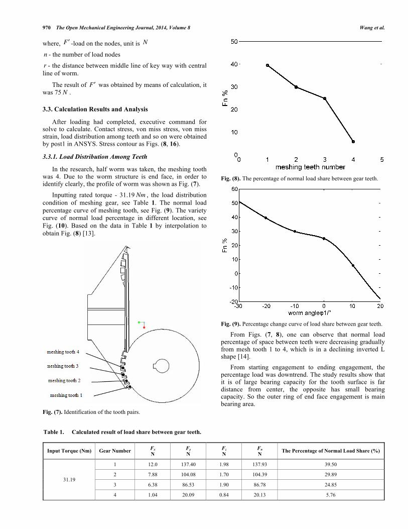
In the research, half worm was taken, the meshing tooth was 4. Due to the worm structure is end face, in order to identify clearly, the profile of worm was shown as Fig. (7).
Inputting rated torque - 31.19 Nm , the load distribution condition of meshing gear, see Table 1. The normal load percentage curve of meshing tooth, see Fig. (9). The variety curve of normal load percentage in different location, see Fig. (10). Based on the data in Table 1 by interpolation to obtain Fig. (8) [13].
Fig. (7). Identification of the tooth pairs.
Fig. (8). The percentage of normal load share between gear teeth.
Fig. (9). Percentage change curve of load share between gear teeth.
From Figs. (7, 8), one can observe that normal load percentage of space between teeth were decreasing gradually from mesh tooth 1 to 4, which is in a declining inverted L shape [14]. From starting engagement to ending engagement, the percentage load was downtrend. The study results show that it is of large bearing capacity for the tooth surface is far distance from center, the opposite has small bearing capacity. So the outer ring of end face engagement is main bearing area.
Table 1. Calculated result of load share between gear teeth.
Input Torque (Nm) Gear Number Fx N
Fy N
Fz N
Fn N The Percentage of Normal Load Share (%)
31.19
1 12.0 137.40 1.98 137.93 39.50
2 7.88 104.08 1.70 104.39 29.89
3 6.38 86.53 1.90 86.78 24.85
4 1.04 20.09 0.84 20.13 5.76
Double-Roller Enveloping End Face Engagement Worm Gear The Open Mechanical Engineering Journal, 2014, Volume 8 971
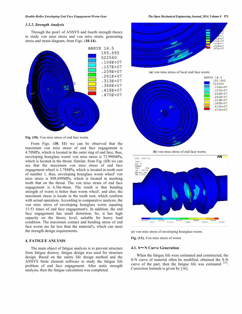
3.3.2. Strength Analysis
Through the post1 of ANSYS and fourth strength theory to study von miss stress and von miss strain, generating stress and strain diagram, from Figs. (10-14).
Fig. (10). Von miss stress of end face worm.
From Figs. (10, 11) we can be observed that the maximum von miss stress of end face engagement is 4.70MPa, which is located in the outer ring of end face, thus, enveloping hourglass worm' von miss stress is 72.998MPa, which is located in the throat. Similar, from Fig. (13) we can see that the maximum von miss stress of end face engagement wheel is 3.78MPa, which is located in tooth root of number 1, thus, enveloping hourglass worm wheel' von miss stress is 898.699MPa, which is located in meshing tooth that on the throat. The von miss strain of end face engagement is 6.36e-4mm. The result is that bending strength of worm is better than worm wheel', and also, the maximum stress is locate in the tooth root, which conform with actual operation. According to comparative analysis, the von miss stress of enveloping hourglass worm equating 15.53 times of end face engagement's. In addition, the end face engagement has small distortion. So, it has high capacity on the theory level, suitable for heavy load condition. The maximum contact and bending stress of end face worm are far less than the material's, which can meet the strength design requirements.
4. FATIGUE ANLYSIS
The main object of fatigue analysis is to prevent structure from fatigue destroy, fatigue design was used for structure design. Based on the safety life design method and the ANSYS finite element software to study the fatigue life problem of end face engagement. After static strength analysis, then the fatigue calculation was completed.
(a) von miss stress of local end face worm.
(b) von miss stress of end face worm.
(c) von miss stress of enveloping hourglass worm.
Fig. (11). Von miss stress of worm.
4.1. S~N Curve Generation
When the fatigue life were estimated and constructed, the S-N curve of material often be modified, obtained the S-N curve of the part, then the fatigue life was estimated [15]. Correction formula is given by [16].

972 The Open Mechanical Engineering Journal, 2014, Volume 8 Wang et al.
σ a =CSCDCLSbψτ
1+ q Kt −1( ) (7)
where,CS -surface quality factors, C D -size factor, CL -load factor, Sb -fatigue strength of material, ψτ -average stress correction factor, q -fatigue sensitive factor, Kt -Theoretical Stress Concentration Factor, σ a - fatigue strength.
(a) von miss stress of end face worm wheel.
(b) von miss stress of local end face worm wheel.
(c) von miss stress of local end face worm wheel.
Fig. (12). Von miss stress of worm wheel.
Fig. (13). Contact stress distribution in the worm gear.
Fig. (14). Von miss strain of end face worm.
By equation (7), by determining parameters, obtained the curve between stress amplitude and cycle failure times as Fig. (15).
Fig. (15). S-N curve of worm.

Double-Roller Enveloping End Face Engagement Worm Gear The Open Mechanical Engineering Journal, 2014, Volume 8 973
Fig. (16). Fatigue sensitivity.
4.2. Calculation Result and Analysis
The fatigue sensitivity of S~N curve is resolved. Based on the result, life, damage and safety factor of worm with load variation were shown in the critical regions [17]. Fatigue sensitivity was shown as Fig. (16), it represents fatigue life could reach 10 million cycles in the safety range, it is very stable [18, 19]. (3) Combination of the results of static mechanical analysis and fatigue theory, based on the sensitivity analysis for fatigue life of end face engagement, obtain the fatigue sensitivity drawing. The results provide theoretical guidance for structural optimization design and modification.
CONFLICT OF INTEREST
The authors confirm that this article content has no conflicts of interest.
ACKNOWLEDGMENTS
This work is supported by National Natural Science Foundation of China (Grant No. 51305356), and Spring Sunshine Plan of Ministry of Education of China(Grant No. 14202505).
REFERENCES
[1] J. L. Xie, Y. Zhang, and Y. Y. Xie, “Dynamic Response and Fatigue Strength of Depressed Center Flat Frame”, Journal of mechanical engineering, vol. 46, no. 8, pp. 16-22, 2010.
[2] Y. Q. Zhang, and G. H. Zhang, “Strength Calculation of Planar Double-Enveloping Hourglass Worm Gear”, Journal of Southwest Jiaotong University, vol. 46, no. 1, pp. 138-142, 2011.
[3] J. S. Tang, and H. R. Meng, “Surface load-capacity of grindable hourglass worm gearing”. Journal of mechanical engineering, vol. 29, no. 6, pp. 26-31, 1993.
[4] L. Nie, “Meshing characteristics and load capacity analysis of elliptical bevel gear”, Chongqing University, 2013.
[5] X. Q. Deng, J. L. Wang, S. A. Chen, and J. G. Wang, “Research overview of anti-backlash end face engagement worm gearing”, Jouranl of HebeiUniversity, vol. 36, no. 2, pp. 111-117, 2015.
[6] X. Q. Deng, “Study on the anti-backlash double-roller enveloping hourglass worm gearing”, Sichuan University, pp. 9-12, 2011.
[7] X. Q. Deng, J. G. Wang, J. F. Zhang, and J. Wu, „Theoretical study on real tooth surface of non-backlash double-roller enveloping hourglass worm”, Journal of Southwest Jiaotong University, vol. 45, no. 2, pp. 222-226, 2010.
[8] V. T. Tran, R. H. Hsu, and C. B. Tsay, “Tooth contact analysis of double-crowned involute helical pairs shaved by a crowning mechanism with parallel shaving cutters”, Mechanism and Machine Theory, 2014.
[9] Z. R. Niu, Y. Gang, and J. Hu, “Research on the degital design method for variable ratio gear of variable ratio gear pair with alternating”, Journal of Sichuan University, vol. 47, no. 2, pp. 184-190, 2015.
[10] J. Qiu, and Y. H. Sun, “Modeling studing of TIWom in the Environment of ANSYS”, Machine Tool & Hydraulics, no.12, pp. 20-23, 2006.
[11] P. S. Sandro, L. M. Sergio, F. Ribeiro, C. B. Lincoln, “Particle swarm optimization for achieving the minimum profile error in honing process”, Precision Engineering, 2014.
[12] F. Yang, W. Y. Li, H. W. Li, and Y. B. Su, “Finite Element Analysis for Gap Disc of No-till Planter”. Journal of agriculture machinery, vol.41, no. 6, pp. 53-55, 2010.
[13] J. Wu. “Design& Machining of Non-Backlash Double-Roller Enveloping Hourglass Worm Gear Pair”, Chengdu: Xihua University, 2009.
[14] X. Q. Deng, J. G. Wang, and M. F. Horstemeyer, “Parametric Study of Meshing Characteristics With Respect to Different Meshing Rollers of the Antibacklash Double-Roller Enveloping Worm Gear”, Journal of Mechanical Design Journal, 2012.
[15] N. Zhao, and H. Li, “The estimation of gear's fatigue life using the modified P-S-N curve”, Modern Manufacturing Enginerring, vol. 5, 2007.
[16] H. Xu, “Safety factor and allowable stress”, China Machine Press, Beijing, 1981.
[17] J. Q. Jin, K. Luo, Z. Feng, and X. R. Wang, “Finite element analysis on elevator of well maintenance vehicle based on Workbench”, Journal of Shenyang University of Technology, vol. 36, no. 3, pp. 286-289, 2014.
[18] G. Said, J. F. Javad, and Y. Maryam. Gear train optimization based on minimum volume/weight design. Mechanism and Machine Theory, 2013.
[19] J. Wang, Y. D. Wang, and B. Z. Chen. “Structural stress method based sensitivity analysis of fatigue life evaluation about weld, structures”, Chinese journal of solid mechanics, vol. 31, pp. 281-284, 2010.
Received: February 17, 2014 Revised: March 21, 2015 Accepted: June 9, 2015 © Wang et al.; Licensee Bentham Open.
This is an open access article licensed under the terms of the (https://creativecommons.org/licenses/by/4.0/legalcode ), which permits unrestricted, non-commercial use, distribution and reproduction in any medium, provided the work is properly cited.