Embed Size (px)
Citation preview

CHINESE JOURNAL OF MECHANICAL ENGINEERING Vol. 26, No. 6, 2013
·1 127·
DOI: 10.3901/CJME.2013.06.1127, available online at www.springerlink.com; www.cjmenet.com; www.cjmenet.com.cn
Plastic Mechanism of Multi-pass Double-roller Clamping Spinning for Arc-shaped Surface Flange
FAN Shuqin*, ZHAO Shengdun, ZHANG Qi, and LI Yongyi
School of Mechanical Engineering, Xi’an Jiaotong University, Xi’an 710049, China
Received January 9, 2013; revised September 4, 2013; accepted September 6, 2013
Abstract: Compared with the conventional single-roller spinning process, the double-roller clamping spinning(DRCS) process can effectively prevent the sheet metal surface wrinkling and improve the the production efficiency and the shape precision of final spun part. Based on ABAQUS/Explicit nonlinear finite element software, the finite element model of the multi-pass DRCS for the sheet metal is established, and the material model, the contact definition, the mesh generation, the loading trajectory and other key technical problems are solved. The simulations on the multi-pass DRCS of the ordinary Q235A steel cylindrical part with the arc-shaped surface flange are carried out. The effects of number of spinning passes on the production efficiency, the spinning moment, the shape error of the workpiece, and the wall thickness distribution of the final part are obtained. It is indicated definitely that with the increase of the number of spinning passes the geometrical precision of the spun part increases while the production efficiency reduces. Moreover, the variations of the spinning forces and the distributions of the stresses, strains, wall thickness during the multi-pass DRCS process are revealed. It is indicated that during the DRCS process the radical force is the largest, and the whole deformation area shows the tangential tensile strain and the radial compressive strain, while the thickness strain changes along the generatrix directions from the compressive strain on the outer edge of the flange to the tensile strain on the inner edge of the flange. Based on the G-CNC6135 NC lathe, the three-axis linkage computer-controlled experimental device for DRCS which is driven by the AC servo motor is developed. And then using the experimental device, the Q235A cylindrical parts with the arc-shape surface flange are formed by the DRCS. The simulation results of spun parts have good consistency with the experimental results, which verifies the feasibility of DRCS process and the reliability of the finite element model for DRCS. Key words: spinning, double-roller clamping, multi-pass, arc-shaped surface
1 Introduction∗
Conventional spinning is commonly known as a process for converting a flat sheet metal blank, usually with an axisymmetric profile, into a hollow shape part by a roller. During the forming process, the roller pushes against the blank, and forces the blank onto a mandrel with the final contour of the desired product[1–2]. Many scholars carried out the researches on the power spinning and simple one-pass conventional spinning. The shear forming forces were analyzed theoretically by KOBAYASHI, et al[3], and using the experimental method the influences of main process parameters such as roller nose radius and roller feed on the spinning force and forming quality of spun cone were investigated by CHEN, et al[4]. The deformation field of the tube spinning process was simulated with the finite
* Corresponding author. E-mail: [email protected] This project is supported by National Natural Science Foundation of
China(Grant Nos. 50905137, 50975222), China Postdoctoral Science Foundation(Grant No. 2012M521757), and Natural Science Foundation of Shaanxi for Youths, China(Grant No. 2012JQ7032) © Chinese Mechanical Engineering Society and Springer-Verlag Berlin Heidelberg 2013
element method by XU, et al[5]. A 3D elastic-plastic FE model for three-roller backward spinning of a cylindrical workpiece was established by HUA, et al[6], and then a practical spinning process was simulated. The effects of roller nose radius and release angle on the forming quality of a hot tube spinning process were investigated by LEXIAN, et al[7]. Ball spinning is a kind of tube spinning and it uses balls instead of rollers. The spinning force components of ball spinning were calculated and the effects of feed ratio and the ball diameter on the spinning force components were analyzed by JIANG, et al[8]. A series of experiments and numerical simulations are carried out to study the evolution of redundant strains in a single-roller flow forming process in one pass by MOHEBBI, et al[9]. The forward flow forming of tubes was simulated by PARSA, et al[10], and then the flow formability of tube materials was calculated. A hot shear spinning process was developed by MORI, et al[11] to form the cast aluminium alloy parts by which the casting defects can be eliminated. The 3D FE model of the cone spinning process with two symmetrical rollers was established by ZHAN, et al[12], and then the effects of the roller feed rate on the spinning force and forming quality were analyzed. The calculation
FAN Shuqin, et al: Plastic Mechanism of Multi-pass Double-roller Clamping Spinning for Arc-shaped Surface Flange
·1 128·
formulas of the spinning forces in flexible spinning of cone were derived by XIA, et al[13], and the effects of the main process parameters, such as the roller feed rate and roller roundness radius were analyzed by the experimental and theoretical methods.
It was reported by KANG, et al[14] that the deformation of conventional spinning in the first pass (the initial blanks are plates) decides the wall thickness of final spun parts. Using an elasto-plastic FE method, the research on the first pass of the spinning process was carried out by LIU, et al[15]. The characteristics of the one-pass deep drawing spinning of cups were studied by XIA, et al[16] and the forming limit diagrams and proper process parameters were obtained. The material deformation mechanism of single-pass conventional spinning was studied by HAMILTON, et al[17]. The mechanism of necking spinning process for non-axisymmetric thin-wall offset tube was investigated by KUANG, et al[18].
The multi-pass conventional spinning is more complicate, compared with single-pass conventional spinning, and some scholars have carried out the researches on the multi-pass conventional spinning. Using the combination of explicit and implicit FE method, a 3D FE model for multi-pass spinning including the spinning process, springback and annealing process was established by ZHAN, et al[19]. LS-DYNA was applied to simulate the multi-pass and die-less spinning processes by LIU[20]. MARC was adopted to simulate the multi-pass neck-spinning process of offset tube by XIA, et al[21], and then the distributions of stress and strain during the forming process were obtained. The FE model for five-pass conventional spinning was built and the variation of spinning forces, distributions of stresses and strains of the workpiece, and variations of energies were analyzed numerically by WANG, et al[22].
DRCS is a new spinning process to form the flanged cylinders, such as fans, ventilators, vents and filters. It has been widely used in industries such as heating, ventilating and air conditioning(HVAC) and shipbuilding.
Conventional processing method of flanged cylinders is cutting, bending and welding[23]. Firstly a steel sheet is cut, bent and welded to form a cylindrical workpiece, and then a flat sheet is cut, bent and welded to form a flange. Finally the cylindrical workpiece and the flange are welded together to form a flanged cylinder. Due to the complicated procedures, the conventional processing method has low production efficiency. In addition, the cutting technology causes the low utilization ratio of material, and the welding technology results in the poor product quality.
Using the DRCS process the flanged cylinder can be directly formed by a cylindrical blank and the forming force of the process is very low just like the conventional spinning process. Because of this simple production procedure the whole manufacturing time is reduced and the forming efficiency is improved. Using the DRCS process no welding seams appear in the flange region, the
mechanical properties and the surface finish of the workpiece are improved greatly and better air flow is obtained in the cylindrical body.
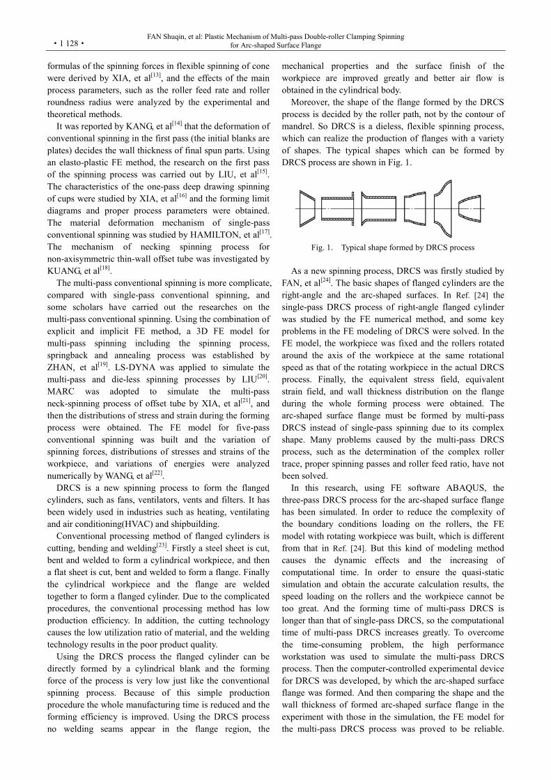
Moreover, the shape of the flange formed by the DRCS process is decided by the roller path, not by the contour of mandrel. So DRCS is a dieless, flexible spinning process, which can realize the production of flanges with a variety of shapes. The typical shapes which can be formed by DRCS process are shown in Fig. 1.
Fig. 1. Typical shape formed by DRCS process
As a new spinning process, DRCS was firstly studied by
FAN, et al[24]. The basic shapes of flanged cylinders are the right-angle and the arc-shaped surfaces. In Ref. [24] the single-pass DRCS process of right-angle flanged cylinder was studied by the FE numerical method, and some key problems in the FE modeling of DRCS were solved. In the FE model, the workpiece was fixed and the rollers rotated around the axis of the workpiece at the same rotational speed as that of the rotating workpiece in the actual DRCS process. Finally, the equivalent stress field, equivalent strain field, and wall thickness distribution on the flange during the whole forming process were obtained. The arc-shaped surface flange must be formed by multi-pass DRCS instead of single-pass spinning due to its complex shape. Many problems caused by the multi-pass DRCS process, such as the determination of the complex roller trace, proper spinning passes and roller feed ratio, have not been solved.
In this research, using FE software ABAQUS, the three-pass DRCS process for the arc-shaped surface flange has been simulated. In order to reduce the complexity of the boundary conditions loading on the rollers, the FE model with rotating workpiece was built, which is different from that in Ref. [24]. But this kind of modeling method causes the dynamic effects and the increasing of computational time. In order to ensure the quasi-static simulation and obtain the accurate calculation results, the speed loading on the rollers and the workpiece cannot be too great. And the forming time of multi-pass DRCS is longer than that of single-pass DRCS, so the computational time of multi-pass DRCS increases greatly. To overcome the time-consuming problem, the high performance workstation was used to simulate the multi-pass DRCS process. Then the computer-controlled experimental device for DRCS was developed, by which the arc-shaped surface flange was formed. And then comparing the shape and the wall thickness of formed arc-shaped surface flange in the experiment with those in the simulation, the FE model for the multi-pass DRCS process was proved to be reliable.
CHINESE JOURNAL OF MECHANICAL ENGINEERING
·1 129·
Furthermore, the FE model was verified by the energy conversation principle offered by the ABAQUS Analysis User’s Manual. Finally the effects of spinning passes on the spinning moment and the forming quality of the spun flange were studied. Furthermore, the variations of spinning forces, the distributions of stresses, strains and the wall thickness on the flange were analyzed. All these have revealed the deformation mechanism of multi-pass DRCS process.
2 Description of Multi-pass DRCS Process
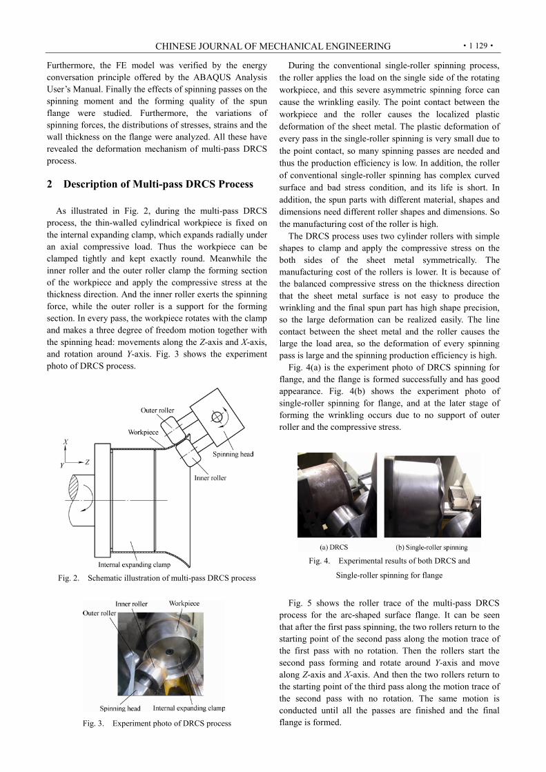
As illustrated in Fig. 2, during the multi-pass DRCS
process, the thin-walled cylindrical workpiece is fixed on the internal expanding clamp, which expands radially under an axial compressive load. Thus the workpiece can be clamped tightly and kept exactly round. Meanwhile the inner roller and the outer roller clamp the forming section of the workpiece and apply the compressive stress at the thickness direction. And the inner roller exerts the spinning force, while the outer roller is a support for the forming section. In every pass, the workpiece rotates with the clamp and makes a three degree of freedom motion together with the spinning head: movements along the Z-axis and X-axis, and rotation around Y-axis. Fig. 3 shows the experiment photo of DRCS process.
Fig. 2. Schematic illustration of multi-pass DRCS process
Fig. 3. Experiment photo of DRCS process
During the conventional single-roller spinning process, the roller applies the load on the single side of the rotating workpiece, and this severe asymmetric spinning force can cause the wrinkling easily. The point contact between the workpiece and the roller causes the localized plastic deformation of the sheet metal. The plastic deformation of every pass in the single-roller spinning is very small due to the point contact, so many spinning passes are needed and thus the production efficiency is low. In addition, the roller of conventional single-roller spinning has complex curved surface and bad stress condition, and its life is short. In addition, the spun parts with different material, shapes and dimensions need different roller shapes and dimensions. So the manufacturing cost of the roller is high.
The DRCS process uses two cylinder rollers with simple shapes to clamp and apply the compressive stress on the both sides of the sheet metal symmetrically. The manufacturing cost of the rollers is lower. It is because of the balanced compressive stress on the thickness direction that the sheet metal surface is not easy to produce the wrinkling and the final spun part has high shape precision, so the large deformation can be realized easily. The line contact between the sheet metal and the roller causes the large the load area, so the deformation of every spinning pass is large and the spinning production efficiency is high.
Fig. 4(a) is the experiment photo of DRCS spinning for flange, and the flange is formed successfully and has good appearance. Fig. 4(b) shows the experiment photo of single-roller spinning for flange, and at the later stage of forming the wrinkling occurs due to no support of outer roller and the compressive stress.
Fig. 4. Experimental results of both DRCS and
Single-roller spinning for flange
Fig. 5 shows the roller trace of the multi-pass DRCS
process for the arc-shaped surface flange. It can be seen that after the first pass spinning, the two rollers return to the starting point of the second pass along the motion trace of the first pass with no rotation. Then the rollers start the second pass forming and rotate around Y-axis and move along Z-axis and X-axis. And then the two rollers return to the starting point of the third pass along the motion trace of the second pass with no rotation. The same motion is conducted until all the passes are finished and the final flange is formed.

FAN Shuqin, et al: Plastic Mechanism of Multi-pass Double-roller Clamping Spinning for Arc-shaped Surface Flange
·1 130·
Fig. 5. Schematic diagram of the roller trace
of multi-pass DRCS process
3 Experimental Investigations Based on the G-CNC6135 NC lathe, the
computer-controlled experimental device for DRCS was developed, as shown in Fig. 6. The main technical parameters of G-CNC6135 NC lathe is shown in Table 1.
Fig. 6. Computer-controlled experimental device for DRCS
Table 1. Main technical parameters of G-CNC6135 NC lathe
Parameter Value Maximum workpiece tactical diameter Dtmax mm 350 Maximum workpiece length Lmax mm 750 Maximum machining diameter Dpmax mm 350 Maximum machining length Lpmax mm 450 Cross travel of tool post Sc mm 178 Longitudinal travel of tool post Sl mm 630 Spindle speed range n (r·min–1 ) 25–1 600 Spindle motor power P / kW 4.5
The necessary components of DRCS experimental
device, internal expanding clamp and spinning head were designed and manufactured, as shown in Fig. 7. It can be seen from Fig. 7 that the internal expanding clamp is fixed on the three-jaw chuck of NC lathe to clamp the cylindrical workpiece, and the spinning head with two rollers is driven by an AC servo motor with a speed reducer, and the clearance between the two rollers can be adjusted according to the workpiece thickness. Then the original lathe tool was replaced by the spinning head which was driven by the servo motor fixed on it and rotate around Y axis, and also was driven by the X axis and Z axis servo motors on the NC lathe, and thus the spinning head can realize the three-axis linkage.
Fig. 7. Necessary components of DRCS experimental device
Furthermore, the type of the servo motor fixed on the spinning head (Y-axis servo motor) is SM130-150-15LFB, and its nominal torque is 15 N·m, nominal power is 2.3 kW, and the speed reducer is the PL160 planetary reducer with the reduction ratio 100:1. The X-axis servo motor is 130STZ5-1-HM, and its nominal torque is 5 N·m, nominal power is 1.0 kW. The Z-axis servo motor is 130STZ7.5-1-HM, and its nominal torque is 7.5 N·m, nominal power is 1.4 kW. The three servo motors were controlled using the computer control system including the motion control card, the computer and the control software to finish the DRCS experiments automatically.
4 Finite Element Analysis
The initial cylindrical workpiece in the DRCS
experiment was made by rolling an ordinary Q235A steel plate up and then welding and abrading. The geometry model of the DRCS process for complex flange is shown in Fig. 8, and its main parameters are shown in Table 2.
The control point of rollers is the bending point marked in Fig. 8(a), and it is defined as the reference point of the rollers in the FE model. p is the vertical distance between the bending point and the bottoms of the rollers, and c is the distance between the clamp position and bending point.
Both the modeling and the simulation of DRCS process are time-consuming and always occupy a lot of computational resources. Thus, it is necessary to choose efficient FE software to build the FE model and simulate the DRCS process, and the FE software must have good

CHINESE JOURNAL OF MECHANICAL ENGINEERING
·1 131·
robustness. According to these requirements, nonlinear FE analysis software ABAQUS/Explicit was used in this study. In addition, some simplifications and reasonable assumptions were made. For example, the blank material was homogeneous, isotropic and incompressible, the rollers and internal expanding clamp were rigid bodies, and no deformation occurred. Furthermore, the temperature effect was neglected.
Fig. 8. Geometry model
Table 2. Main parameters of the geometry model
Parameter Value Diameter of initial workpiece D0 mm 200 Wall thickness of initial workpiece δ0 mm 1 Height of initial workpiece L mm 160 Roller clamping length l mm 54 Vertical distance between the bending point and the bottoms of the rollers p mm
1
Distance between the clamp position and bending point c mm
5
Flange width W / mm 10, 20, 30 Diameter of the final part D1 mm 220, 240, 260 Arc radius of arc-shaped surface flange R mm 134, 90, 122 Diameter of rollers d mm 100 Height of rollers h mm 60 Round radius of rollers r mm 2
Ordinary Q235A steel was chosen as the material of the
workpiece in the experiment and simulation of the DRCS process, and its main material parameters were determined using the tensile test, and they are shown in Table 3. The true stress-strain curve of Q235A is shown in Fig. 9.
Table 3. Material parameters of Q235A
Material parameter Value Young’s modulus E GPa 210 Poisson ratio υ 0.3 Density ρ (kg·m–3) 7 850 Yield stress σs MPa 200
Mass fraction ω %
C 0.18 Mn 0.47 Si 0.26 S 0.049 P 0.044 Fe Balance
Fig. 9. True stress-strain curve for the material
Using above parameters, the 3D FE model for the DRCS
process of arc-shaped surface flange was established, as shown in Fig. 10.
Fig. 10. FE model of DRCS process for arc-shaped surface flange
In the FE model, the workpiece rotates with the clamp
and the rollers make a three degree of freedom motion. The roller feed rate f is defined as the rotating angle of the rollers when the workpiece rotates through a complete cycle around the main spindle. In this study, the roller feed rate f is 0.01 rad·r–1.
As the DRCS process involves only local deformation, a small portion of the workpiece is in contact with the rollers at any given time. Furthermore, the workpiece rotates with the clamp throughout the forming process, which makes the workpiece bear cyclic load, and thus the contact condition varies frequently and rapidly. During the DRCS process, both the contact between the workpiece and internal expanding clamp and the contact between the workpiece and rollers are complex and dynamic. So the contact pairs were defined between the internal expanding clamp and the cylindrical workpiece, as well as between the rollers and the cylindrical workpiece. In addition, the coulomb friction formulation and penalty contact method were used.
The internal expanding clamp and rollers were simplified as discrete rigid parts, meshed by 3D bilinear rigid quadrilateral element with four nodes. The workpiece was defined as a deformable shell, meshed by S4R element which is 4-node doubly curved general-purpose shell, reduced integration with hourglass control. The flange

FAN Shuqin, et al: Plastic Mechanism of Multi-pass Double-roller Clamping Spinning for Arc-shaped Surface Flange
·1 132·
forming area of the workpiece had a higher density than the rest of the workpiece.
5 Results and Discussion
5.1 Verification of FE analysis model In order to verify the FE model of DRCS process for
arc-shaped surface flange, experiments were carried out in this work. Fig. 11 shows both the simulation result and experiment result of single-pass DRCS process for arc-shaped surface flange with the flange width W 30 mm.
Fig. 11. Single-pass DRCS (Flange width W 30 mm)
It can be seen from Fig. 11 that the simulation result is consistent with the experiment result, and there are obvious bulges and wrinkles on the surface of flange.
Fig. 12 shows both the simulation result and experiment result of two-pass DRCS process for arc-shaped surface flange with the flange width W 20 mm. It can be seen from Fig. 12 that the simulation result has a good appearance, which is consistent with the experiment result.
Fig. 12. Two-pass DRCS (Flange width W 20 mm) Then the wall thickness distribution of the final spun part
with the flange width 20 mm obtained from the simulation is compared with that from the experiment, as shown in Fig. 13.
Fig. 13 (a) shows the measuring points of wall thickness, and there are 10 measuring points which distribute on the outer edge of the flange with the interval of 3 mm. The distance between the first measuring point and the last one is 27mm. It can be seen from Fig. 13 (b) that the wall thickness distributions of measuring points obtained from simulation is consistent with that of experiment, and the wall thickness increases gradually from the outer edge to
the inner edge of the flange. The maximum relative error of wall thickness between experimental and simulation results is 1.6 %, which is mainly due to the simplification of the model and the measurement error in the experiment. Thus, the FE model adopted in this study is reliable and practical.
Fig. 13. Comparison of wall thickness of the final spun part
In addition, ABAQUS offers the energy conversation
principle, and it is a criterion to judge whether the simulation process is quasi-static. It can be known by ABAQUS Analysis User’s Manual[25] that the FE model is reliable if the ratio of kinetic energy of the deformable material to its internal energy is not exceed 10 % during the mostly simulation time. And the ratio of artificial strain energy to internal energy is not greater than 5 %. Finally the variations of energies ratio were obtained in the simulation of DRCS, and they are in agreement with the energy criterion, as shown in Fig. 14. So it can be concluded that the FE model of DRCS is reliable.
Fig. 14. Variations of energy ratio
CHINESE JOURNAL OF MECHANICAL ENGINEERING
·1 133·
5.2 FE results analysis
5.2.1 Effects of spinning passes on the shape error of formed arc-shaped surface flange
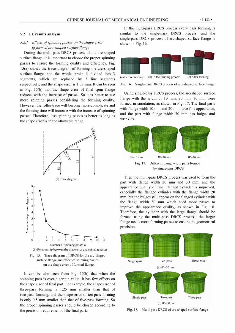
During the multi-pass DRCS process of the arc-shaped surface flange, it is important to choose the proper spinning passes to ensure the forming quality and efficiency. Fig. 15(a) shows the trace diagram of forming the arc-shaped surface flange, and the whole stroke is divided into 3 segments, which are replaced by 3 line segments respectively, and the shape error is 1.38 mm. It can be seen in Fig. 15(b) that the shape error of final spun flange reduces with the increase of passes. So it is better to use more spinning passes considering the forming quality. However, the roller trace will become more complicate and the forming time will increase with the increase of spinning passes. Therefore, less spinning passes is better as long as the shape error is in the allowable range.
Fig. 15. Trace diagram of DRCS for the arc-shaped
surface flange and effect of spinning passes on the shape error of formed flange
It can be also seen from Fig. 15(b) that when the
spinning pass is over a certain value, it has few effects on the shape error of final part. For example, the shape error of three-pass forming is 1.25 mm smaller than that of two-pass forming, and the shape error of ten-pass forming is only 0.5 mm smaller than that of five-pass forming. So the proper spinning passes should be chosen according to the precision requirement of the final part.
In the multi-pass DRCS process every pass forming is similar to the single-pass DRCS process, and the single-pass DRCS process of arc-shaped surface flange is shown in Fig. 16.
Fig. 16. Single-pass DRCS process of arc-shaped surface flange Using single-pass DRCS process, the arc-shaped surface
flange with the width of 10 mm, 20 mm, 30 mm were formed in simulation, as shown in Fig. 17. The final parts with flange width 10 mm and 20 mm have fine appearance, and the part with flange width 30 mm has bulges and wrinkles.
Fig. 17. Different flange width parts formed by single-pass DRCS
Then the multi-pass DRCS process was used to form the
part with flange width 20 mm and 30 mm, and the appearance quality of final flanged cylinder is improved, especially the flanged cylinder with the flange width 20 mm, but the bulges still appear on the flanged cylinder with the flange width 30 mm which need more passes to improve the appearance quality, as shown in Fig. 18. Therefore, the cylinder with the large flange should be formed using the multi-pass DRCS process, the larger flange needs more forming passes to ensure the geometrical precision.
Fig. 18. Multi-pass DRCS of arc-shaped surface flange

FAN Shuqin, et al: Plastic Mechanism of Multi-pass Double-roller Clamping Spinning for Arc-shaped Surface Flange
·1 134·
5.2.2 Effects of spinning passes on the spinning moment and the wall thickness of final flange
Using single-pass, two-pass and three-pass DRCS process, the arc-shaped surface flange with the width of 20 mm was formed in simulation, and the effects of spinning passes on the spinning moment and the wall thickness of final flange were obtained.
There is no obvious difference of the maximum moment between single-pass spinning and two-pass spinning, both are about 50 N·m, while the maximum moment of three-pass spinning reduces obviously, is about 40 N·m, as shown in Fig. 19. To the multi-pass spinning, the moment of the first pass spinning is the largest, and the spinning moments of the subsequent passes decrease gradually. With the increase of passes, the moment has a tendency to reduce.
Fig. 19. Spinning moment of different spinning pass DRCS
The more passes can improve the shape precision of the final part, and make the part formed completely which results in the increase of the wall thickness reduction ratio. Fig. 20 shows the effect of spinning passes on the maximum wall thickness reduction ratio (ψmax), and it can be seen that the wall thickness reduction ratio increases with the spinning passes.
Fig. 20. Curve of maximum wall thickness reduction ratio versus number of spinning passes
5.2.3 Spinning forces To the three-pass DRCS for the arc-shaped surface
flange with the width of 20 mm, the spinning forces were analyzed.
In this study, the force along the axis of the mandrel (Z-axis as shown in Fig. 2) was defined as axial spinning force and the force along the radial direction of the mandrel was defined as radial force (X-axis as shown in Fig. 2). As shown in Fig. 21, the change process of spinning force includes five stages, and they are three forward passes (stage1, stage 3, stage 5) and two backward passes (stage 2, stage 4). In the two backward pass forming the rollers don’t exert the load on the workpiece, so the forces are zero. Thus the forming process was called as three-pass DRCS process in this study.
Fig. 21. Spinning forces

CHINESE JOURNAL OF MECHANICAL ENGINEERING
·1 135·
It can be seen that the radial force is the greatest throughout the whole DRCS process, and this is because the increase of diameter is dominant during the DRCS process, which is different from the conventional spinning in which the axial force is the largest [16, 22]. While the axial force and tangential force is small, compared with the radial force. Furthermore, in the first pass the tangential force is greater than the axial force, because under the action of the rollers the workpiece expands in tangential direction at this stage.
With the progress of the roller passes, both the radial force and tangential forces decrease gradually, while the axial force gradually increases and is greater than the tangential force in the third pass. It may be because the more material deformations occur in both radial and tangential directions during the earlier stage and in the axial direction during the later stage. As shown in Fig. 21, the obvious increase of the axial force can be seen at the last two passes. This is because the rollers squeeze the material tightly in axial direction at these two stages.
To the three-pass DRCS for the arc-shaped surface flange with the width of 20 mm, the distributions of stresses and strains analyzed.
5.2.4 Stresses In this section, radial and tangential stress distributions
on the flange at the initial stage of the first forward pass (t 0.287 s) are discussed.
It can be seen from Fig. 22(a), the roller contact area (Region B) shows the maximum compressive tangential stress, which will reduce to the lower compressive tangential stress when Region B rotates away from the rollers, as shown in the Region C. Both sides of the roller contact area show the tensile tangential stress, as shown in the Region A, which will reduce to the lower tensile tangential stress when Region B rotates away from the rollers, as shown in the Region D.
It can be seen from Fig. 22(b), the roller contact area (Region B) shows the maximum compressive radial stress, and the both sides of the roller contact area (Region A) show the high tensile radial stress. With the rotation of workpiece, the Region B will rotate away from the rollers, and then the radial stress in the Region B changes from the high compressive state to the lower tensile state, as shown in the Region C. In addition, the radial stress in the Region A changes from tensile state into the lower tensile state too.
5.2.5 Strains
In this section, the distributions of tangential strain, radial strain and thickness strain on the flange at the initial stage of the first forward pass (t 0.287 s) are discussed.
It can be seen in Fig. 23 that the flange area shows tensile tangential strain and compressive radial strain, and both the maximum tensi le tangential strain and compressive radial strain are at the outer edge of the flange. Along the generatrix direction the thickness strain changes
from compressive strain to tensile strain, and the maximum compressive thickness strain appear at the outer edge of the flange, while the maximum tensile thickness strain appear at the inner edge of the flange.
Fig. 22. Distribution of stresses at the initial stage
of the first forward pass
On the deformation zone of final formed part 20 points
are chosen as abscissa, and these points are named as 1, 2, 3…, 19, and 20 from the outer edge to the inner edge of the flange. The ordinate is the strain of corresponding point, as shown in Fig. 24. It can be seen that the strains at the inner edge of the flange are small, the strains increase from the inner edge to the outer edge of the flange. Thus the diameter of workpiece enlarges and the wall thickness on the outer edge of the flange reduces.
5.2.6 Wall thickness During the three-pass DRCS process of the arc-shaped
surface flange with the width of 20 mm, the distribution of the wall thickness is shown in Fig. 25. Likewise, 20 points on the deformation zone are chosen as abscissa, and the ordinate is the wall thickness of corresponding point.
As shown in Fig. 25, in every pass forming the outer edge of flange has the minimum wall thickness, and along the generatrix direction the wall thickness increases gradually from the outer to the inner, and the maximum wall thickness appear on the inner edge. In addition, the wall thickness difference after the first pass forming is the smallest, and with the increase of spinning passes, the

FAN Shuqin, et al: Plastic Mechanism of Multi-pass Double-roller Clamping Spinning for Arc-shaped Surface Flange
·1 136·
wall thickness of outer edge becomes smaller and smaller, and the wall thickness difference becomes greater and greater.
Fig. 23. Distribution of strains
Fig. 24. Final distribution of strains
Fig. 25. Wall thickness distribution of arc-shaped surface flange formed by three-pass DRCS
6 Conclusions Using numerical simulation and experimental methods,
the investigations on the multi-pass DRCS are carried out, and the followings have been concluded:
(1) Less spinning passes is better as long as the shape error is in the allowable range, and the larger flange needs the more passes forming to ensure the geometrical precision. During the multi-pass DRCS process, with the increase of passes the spinning moment has a tendency to reduce, while the wall thickness reduction ratio increases.
(2) During the whole DRCS process, the radial spinning force is the greatest among three spinning force components. In the first forward pass the tangential spinning force is greater than the axial force. Both the radial spinning force and tangential forces decrease gradually with the progress of the roller passes, while the axial force gradually increases especially at the last two passes and is greater than the tangential force in the third pass.
(3) The roller contact area shows the maximum compressive tangential stress and maximum compressive radial stress. When the roller rotates away, the high compressive tangential stress on the roller contact area reduces to the lower compressive tangential stress, and the high compressive radial stress changes into the lower tensile radial stresses.
(4) The flange area shows tensile tangential strain and compressive radial strain, and both the maximum tensile tangential strain and compressive radial stain are at the outer edge of the flange. Along the generatrix direction the thickness strain changes from compressive strain to tensile strain, and the maximum compressive thickness strain appear at the outer edge of the flange, while the maximum tensile thickness strain appear at the inner edge of the flange.
(5) In every pass forming the outer edge of flange has the minimum wall thickness, and along the generatrix direction the wall thickness increases gradually from the outer to the inner, and the maximum wall thickness appear on the inner edge. In addition, the wall thickness difference increases

CHINESE JOURNAL OF MECHANICAL ENGINEERING
·1 137·
with the increase of spinning passes.
References [1] WONG C C, DEAM T A, LIN J. A review of spinning, shear
forming and flow forming processes[J]. International Journal of Machine Tools and Manufacture, 2003, 43(14): 1 419–1 435.
[2] MUSIC O, ALLWOOD J M, KAWAI K. A review of the mechanics of metal spinning[J]. Journal of Materials Processing Technology, 2010, 210(1): 3–23.
[3] KOBAYASHI S, HALL I K, THOMSEN E G. A theory of shear spinning of cones[J]. Journal of Engineering for Industry: Transactions of the ASME, 1961, 83: 485–495.
[4] CHEN M D, HSU R Q, FUH K H. Forecast of shear spinning force and surface roughness of spun cones by employing regression analysis[J]. International Journal of Machine Tools and Manufacture, 2001, 41(12): 1 721–1 734.
[5] XU Yi, ZHANG Shihong, LI Ping, et al. 3D rigid-plastic FEM numerical simulation on tube spinning[J]. Journal of Materials Processing Technology, 2001, 113(1–3): 710–713.
[6] HUA F A, YANG Y S, ZHANG Y N, et al. Three-dimensional finite element analysis of tube spinning[J]. Journal of Materials Processing Technology, 2005, 168(1): 68–74.
[7] LEXIAN H, DARIANI B M. Effect of roller nose radius and release angle on the forming quality of a hot-spinning process using a non-linear finite element shell analysis[J]. Proceedings of the Institution of Mechanical Engineers, Part B: Journal of Engineering Manufacture, 2009, 223(6): 713–722.
[8] JIANG Shuyong, REN Zhengyi. Analysis of mechanics in ball spinning of thin-walled tube[J]. Chinese Journal of Mechanical Engineering, 2008, 21(1): 25–30.
[9] MOHEBBI M S, AKBARZADEH A. Experimental study and FEM analysis of redundant strains in flow forming of tubes[J]. Journal of Materials Processing Technology, 2010, 210(2): 389–395.
[10] PARSA M H, PAZOOKI A M A, AHMADABADI M N. Flow- forming and flow formability simulation[J]. International Journal of Advanced Manufacturing Technology, 2009, 42(5–6): 463–473.
[11] MORI K, ISHIGURO M, ISOMURA Y. Hot shear spinning of cast aluminium alloy parts[J]. Journal of Materials Processing Technology, 2009, 209(7): 3 621–3 627.
[12] ZHAN Mei, YANG He, ZHANG Jinhui, et al. 3D FEM analysis of influence of roller feed rate on forming force and quality of cone spinning[J]. Journal of Materials Processing Technology, 2007, 187–188: 486–491.
[13] XIA Qinxiang, SUSUMU S. Analysis on the spinning forces in flexible spinning of cones[J]. Chinese Journal of Mechanical Engineering, 2003, 16(4): 376–378.
[14] KANG Dachang, GAO Xicheng, MENG Xiaofeng, et al. Study on the deformation mode of conventional spinning of plates[J]. Journal of Materials Processing Technology, 1999, 91(1–3): 226–230.
[15] LIU Jianhua, YANG He, LI Yuqiang. A study of stress and strain distributions of first-pass conventional spinning under different roller-traces[J]. Journal of Materials Processing Technology, 2002, 129(1–3): 326–329.
[16] XIA Qinxiang, SHIMA S, KOTERA H, et al. A study of the one-path deep drawing spinning of cups[J]. Journal of Materials Processing Technology, 2005, 159(3): 397–400.
[17] HAMILTON S, LONG H. Analysis of conventional spinning process of a cylindrical part using finite element method[J]. Steel Research International, 2008, 79(1): 632–639.
[18] KUANG Weihua, XIA Qinxiang, RUAN Feng. Mechanism research for 3D non-axisymmetric thin-wall tube offset spinning[J]. Chinese Journal of Mechanical Engineering, 2006, 19(2): 217–222.
[19] ZHAN Mei, ZHOU Qiang, YANG He, et al. Establishment of 3D FEM Model of multi-pass spinning[J]. Chinese Journal of Mechanical
Engineering, 2007, 20(4): 19–23. [20] LIU Chunho. The simulation of the multi-pass and die-less spinning
process[J]. Journal of Materials Processing Technology, 2007, 192–193: 518–524.
[21] XIA Qinxiang, XIE Shiwei, HUO Y L, et al. Numerical simulation and experimental research on the multi-pass neck-spinning of non-axisymmetric offset tube[J]. Journal of Materials Processing Technology, 2008, 206(1–3): 500–508.
[22] WANG Lin, LONG Hui. Investigation of material deformation in multi-pass conventional metal spinning[J]. Materials and Design, 2011, 32(5): 2 891–2 899.
[23] ZHAO Shengdun, SHEN Yajing, SHANG Wanfeng, et al. The actuality and trend of spinning machine for manufacture of fan casting[C]//The Tenth National Plastic Engineering Academic Annual Meeting, The Third Session of International Seminar on Advanced Plastic Processing Technology, Nanchang, China, October, 2007: 557–562. ( in Chinese)
[24] FAN Shuqin, ZHAO Shengdun, ZHANG Qi, et al. Finite-element modeling of a novel flanging process on a cylinder with a large diameter-thickness ratio[J]. Proceedings of the Institution of Mechanical Engineers, Part B: Journal of Engineering Manufacture, 2011, 225(7): 1 117–1 127.
[25] ABAQUS, Inc. ABAQUS analysis user’s manual[M]. Version 6.8, 2008.
Biographical notes FAN Shuqin, born in 1977, is currently a post doctorate at School of Mechanical Engineering, Xi’an Jiaotong University, China. She received her PhD degree from School of Mechanical Engineering, Xi’an Jiaotong University, China, in 2011. Her research interests include material forming theoretical analysis and numerical simulation, etc. Tel: +86-29-82668607; E-mail: [email protected] ZHAO Shengdun, born in 1962, is a professor at School of Mechanical Engineering, Xi’an Jiaotong University, China. He received his PhD degree from School of Mechanical Engineering, Xi’an Jiaotong University, China, in 1997. His research interests include plastic forming technology and equipment, computer control of mechanical-electrical-hydraulic system, fluid transmis- sion and control, etc. Tel: +86-29-82668607; E-mail: [email protected] ZHANG Qi, born in 1978, is a currently an associate professor at School of Mechanical Engineering, Xi’an Jiaotong University, China. He received his PhD degree from School of Materials Science and Engineering, Harbin Institute of Technology, China, in 2007. His research interests include material forming theoretical analysis and numerical simulation, etc. Tel: +86-29-82668607; E-mail: [email protected] LI Yongyi, born in 1986, is currently a doctoral candidate at School of Mechanical Engineering, Xi’an Jiaotong University, China. His research interests include advanced plastic forming technology and equipment, direct-drive electromechanical system, etc. Tel: +86-29-82668607; E-mail: [email protected]


![LOW COST AUTOMATION USING ELECTRO PNEUMATIC SYSTEM … · fixed station through a roller. ... The indexing mechanism is achieved through limit switches for every 72º [1]. The clamping](https://img.pdfslide.us/doc/110x75/5e8aa80ee1526458c604250e/low-cost-automation-using-electro-pneumatic-system-fixed-station-through-a-roller.jpg)