Embed Size (px)
Citation preview
International Journal of Mechanical And Production Engineering, ISSN: 2320-2092, Volume- 2, Issue- 4, April-2014
Theoretical & CFD Analysis Of De Laval Nozzle
33
THEORETICAL & CFD ANALYSIS OF DE LAVAL NOZZLE
1NIKHIL D. DESHPANDE, 2SUYASH S. VIDWANS, 3PRATIK R. MAHALE, 4RUTUJA S. JOSHI, 5K. R. JAGTAP
1,2,3,4,5Department of Mechanical Engineering, Sinhgad Institute of Technology and Science, Pune, India
Email; [email protected], [email protected],[email protected] Abstract — de Laval nozzles are mechanical devices which are used to convert the thermal and pressure energy into useful kinetic energy. The values of temperature, pressure and velocity should be available at every section of the nozzle so as to design the nozzle shape, insulation and cooling arrangements. This paper aims at providing theoretical formulae to calculate the above. The validation of these formulae is carried out using the Computational Fluid Dynamics (CFD) software ANSYS Fluent. Keywords — De Laval nozzle, Theoretical equations, Computational Fluid Dynamics, ANSYS Fluent. I. INTRODUCTION A de Laval nozzle was invented by Gustaf de Laval, a Swedish inventor. It is a converging-diverging type of nozzle, generally employed to provide supersonic jet velocity at the exit of the nozzle. In this paper, analysis of de Laval nozzle is carried out theoretically by formulating required nozzle equations and the results have been validated by computer simulation using the CFD software ANSYS FLUENT. Firstly, velocity, temperature and pressure have been calculated theoretically at different cross-sections of the nozzle using the formulated equations. Secondly, the theoretical results are verified with the help of computer simulation approach. II. THEORETICAL FORMULATION OF
NOZZLE The equations used below are for one dimensional nozzle flow. It corresponds to the idealization and simplification of full two or three dimensional flow equations and real aero-thermochemical behaviour. The suffixes ch, th, x denote chamber, throat, and cross section at a particular length from the inlet of the nozzle respectively. Nomenclature of symbols used is as follows: P – Pressure (Pa) T – Temperature (K) V – Velocity (m/s) g – Gravitational acceleration (m/s2) z – Height (m) A – Area (m2) Cp – Specific heat at constant pressure (J/kg K) Cv – Specific heat at constant volume (J/kg K) γ – Adiabatic index (Cp/Cv) h – Enthalpy (J) R – Specific gas constant (J/kg K) ρ – Density (kg/m3)
– Heat input to the system (J) – Work done by the system (J) – Mass flow rate (kg/s)
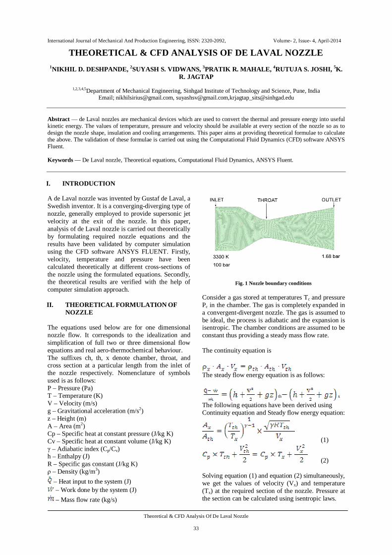
Fig. 1 Nozzle boundary conditions
Consider a gas stored at temperatures Tc and pressure Pc in the chamber. The gas is completely expanded in a convergent-divergent nozzle. The gas is assumed to be ideal, the process is adiabatic and the expansion is isentropic. The chamber conditions are assumed to be constant thus providing a steady mass flow rate. The continuity equation is
The steady flow energy equation is as follows:
th x The following equations have been derived using Continuity equation and Steady flow energy equation:
(1)
(2) Solving equation (1) and equation (2) simultaneously, we get the values of velocity (Vx) and temperature (Tx) at the required section of the nozzle. Pressure at the section can be calculated using isentropic laws.
International Journal of Mechanical And Production Engineering, ISSN: 2320-2092, Volume- 2, Issue- 4, April-2014
Theoretical & CFD Analysis Of De Laval Nozzle
34
TABLE I THEORETICAL RESULTS
III. COMPUTER SIMULATION OF
NOZZLE CFD is an engineering tool that assists experimentation. The following steps were performed in CFD of nozzle: Modelling, meshing, pre-processing, solution, post-processing. A. Modelling The 2-Dimensional modelling of the nozzle was done using CATIA-V5 and file was saved in .stp format. The dimensions of the de Laval nozzle are presented in the table given below.
TABLE II NOZZLE DIMENSIONS
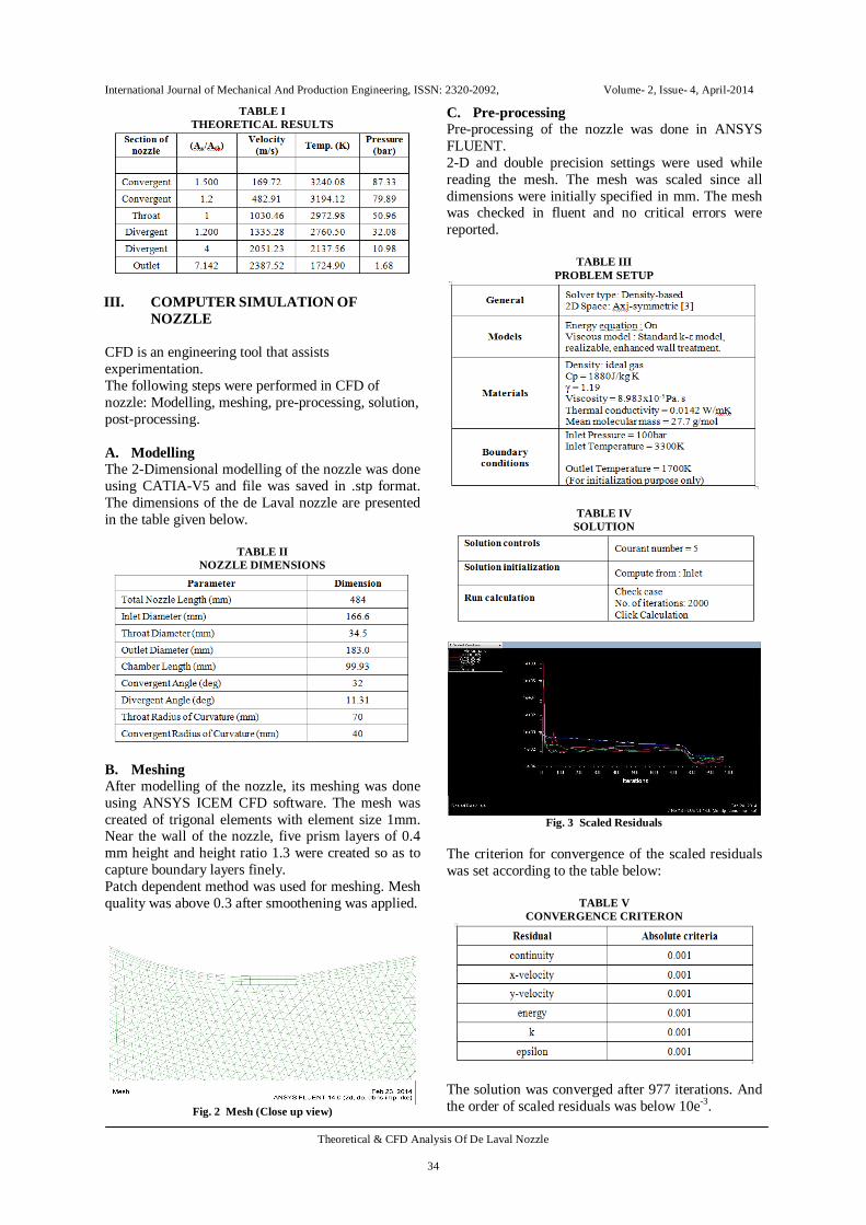
B. Meshing After modelling of the nozzle, its meshing was done using ANSYS ICEM CFD software. The mesh was created of trigonal elements with element size 1mm. Near the wall of the nozzle, five prism layers of 0.4 mm height and height ratio 1.3 were created so as to capture boundary layers finely. Patch dependent method was used for meshing. Mesh quality was above 0.3 after smoothening was applied.
Fig. 2 Mesh (Close up view)
C. Pre-processing Pre-processing of the nozzle was done in ANSYS FLUENT. 2-D and double precision settings were used while reading the mesh. The mesh was scaled since all dimensions were initially specified in mm. The mesh was checked in fluent and no critical errors were reported.
TABLE III PROBLEM SETUP
TABLE IV SOLUTION
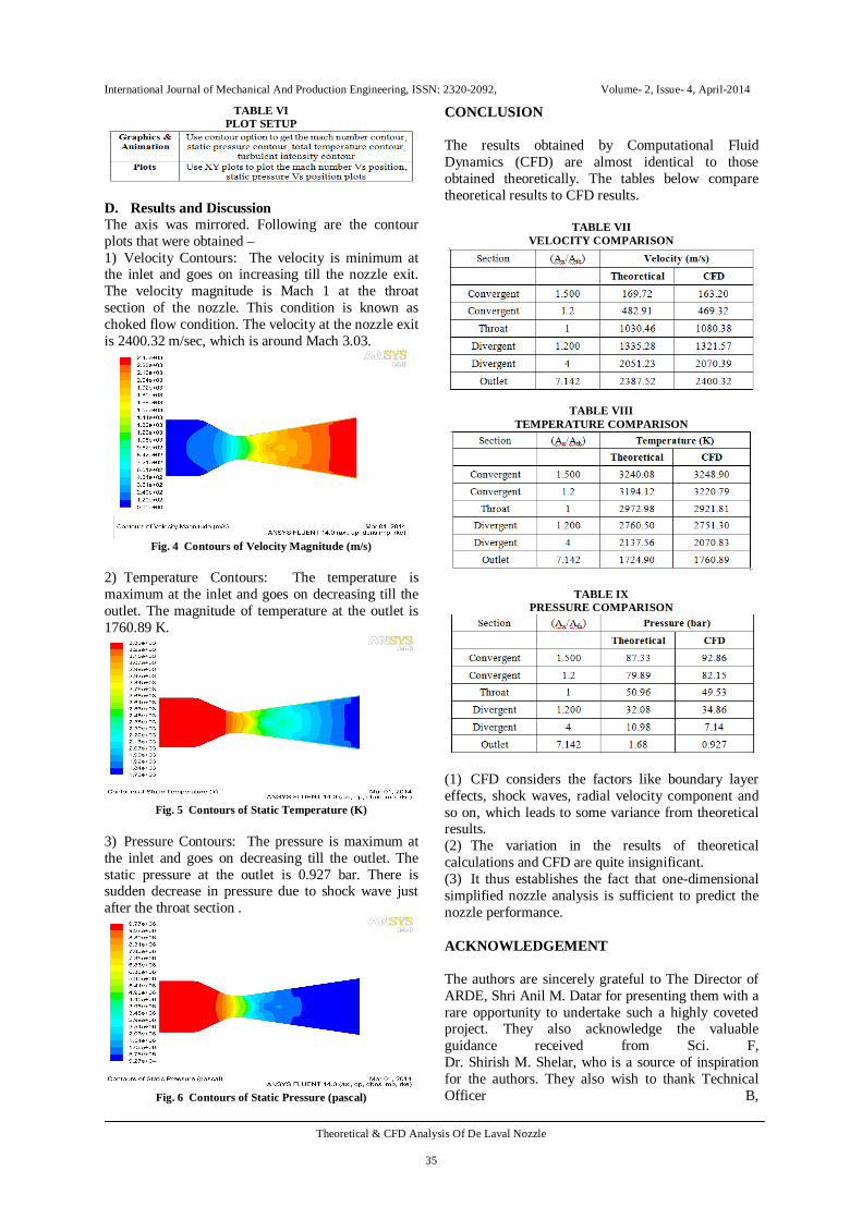
Fig. 3 Scaled Residuals
The criterion for convergence of the scaled residuals was set according to the table below:
TABLE V CONVERGENCE CRITERON
The solution was converged after 977 iterations. And the order of scaled residuals was below 10e-3.
International Journal of Mechanical And Production Engineering, ISSN: 2320-2092, Volume- 2, Issue- 4, April-2014
Theoretical & CFD Analysis Of De Laval Nozzle
35
TABLE VI PLOT SETUP
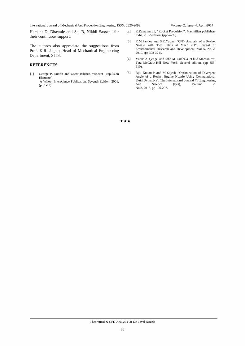
D. Results and Discussion The axis was mirrored. Following are the contour plots that were obtained – 1) Velocity Contours: The velocity is minimum at the inlet and goes on increasing till the nozzle exit. The velocity magnitude is Mach 1 at the throat section of the nozzle. This condition is known as choked flow condition. The velocity at the nozzle exit is 2400.32 m/sec, which is around Mach 3.03.
Fig. 4 Contours of Velocity Magnitude (m/s)
2) Temperature Contours: The temperature is maximum at the inlet and goes on decreasing till the outlet. The magnitude of temperature at the outlet is 1760.89 K.
Fig. 5 Contours of Static Temperature (K)
3) Pressure Contours: The pressure is maximum at the inlet and goes on decreasing till the outlet. The static pressure at the outlet is 0.927 bar. There is sudden decrease in pressure due to shock wave just after the throat section .
Fig. 6 Contours of Static Pressure (pascal)
CONCLUSION
The results obtained by Computational Fluid Dynamics (CFD) are almost identical to those obtained theoretically. The tables below compare theoretical results to CFD results.
TABLE VII VELOCITY COMPARISON
TABLE VIII TEMPERATURE COMPARISON
TABLE IX PRESSURE COMPARISON
(1) CFD considers the factors like boundary layer effects, shock waves, radial velocity component and so on, which leads to some variance from theoretical results. (2) The variation in the results of theoretical calculations and CFD are quite insignificant. (3) It thus establishes the fact that one-dimensional simplified nozzle analysis is sufficient to predict the nozzle performance. ACKNOWLEDGEMENT The authors are sincerely grateful to The Director of ARDE, Shri Anil M. Datar for presenting them with a rare opportunity to undertake such a highly coveted project. They also acknowledge the valuable guidance received from Sci. F, Dr. Shirish M. Shelar, who is a source of inspiration for the authors. They also wish to thank Technical Officer B,
International Journal of Mechanical And Production Engineering, ISSN: 2320-2092, Volume- 2, Issue- 4, April-2014
Theoretical & CFD Analysis Of De Laval Nozzle
36
Hemant D. Dhawale and Sci B, Nikhil Saxsena for their continuous support. The authors also appreciate the suggestions from Prof. K.R. Jagtap, Head of Mechanical Engineering Department, SITS. REFERENCES [1] George P. Sutton and Oscar Biblarz, “Rocket Propulsion
Elements”, A Wiley- Interscience Publication, Seventh Edition, 2001, (pp 1-99).
[2] K.Ramamurthi, “Rocket Propulsion”, Macmillan publishers India, 2012 edition, (pp 54-89).
[3] K.M.Pandey and S.K.Yadav, “CFD Analysis of a Rocket Nozzle with Two Inlets at Mach 2.1”, Journal of Environmental Research and Development, Vol 5, No 2, 2010, (pp 308-321).
[4] Yunus A. Çengel and John M. Cimbala, “Fluid Mechanics”, Tata McGraw-Hill New York, Second edition, (pp 853- 910).
[5] Biju Kuttan P and M Sajesh, "Optimization of Divergent Angle of a Rocket Engine Nozzle Using Computational Fluid Dynamics", The International Journal Of Engineering And Science (Ijes), Volume 2, No 2, 2013, pp 196-207.