Embed Size (px)
Citation preview

THEORETICAL ANALYSIS OF LATERAL RESPONSE DUETO TORSIONAL EXCITATION OF GEARED ROTORS
J. S. RAOtDepartment of Mechanical Engineering, Indian Institute of Technology, New Delhi-110 016, India
T. N. SHIAU and J. R. CHANGGraduate Institute of Mechanical Engineering, National Chung Cheng University, 621 Chia Yi,
Taiwan, Republic of China
(Received 6 June 1996; in revised form 26 March 1997)
Abstract—This paper is concerned with lateral response of geared rotors due to torsional excitation.Usually torsional response is determined due to excitation torque, such as short circuit torque, to deter-mine the safety of a turbo generator set and the coupling of bending and torsion in such an analysis isignored. Such an analysis gives an accurate prediction only when the bending natural frequencies arenot close to the spin speed and its higher as well as lower orders. In this work, the coupling betweenbending and torsion due to gears as well as the effect of axial torque on bending vibrations is takeninto account to determine the coupled lateral and torsional response due to torsional excitation.Examples are given which illustrate the importance of such coupling mechanism giving rise to largeamplitudes of bending vibrations which may be harmful to the operation of geared turbine rotors. Theeffect of axial torque is shown to be less significant, even when the rotor runs at the bending naturalfrequency and is subjected to a short circuit torque.
NOMENCLATURE
A—cross-section area of the shaftC—cos 4>p
[C]—damping matrixc—damping coefficient
c,.,,, c..—direct damping coefficientscr=< c=v—cross-coupled damping coefficients
E—Young's modulusF—force
Fs—force applied by systemG—shear modulus
[G]—gyroscopic matrix/—second moment of area
/D. h—diametral and polar mass momentsJ—polar second moment of areaK—bearing stiffness
** /o.-U)[K\—stiffness matrixK—shear form factorkt,—gear mesh stiffness
krr, kz-_—direct stiffness coefficientskyz, k:y—cross-coupled stiffness coefficients
/'(l-t-O)
/—length of shaft elementM—mass
[M]—mass matrixN,—ith shape functionq,—nodal displacements
i"!, ri—base circle radii of 1st and 2nd gearS—sin (/>,,
[S]—gear mesh stiffness matrices.?—distance measured along coordinate X
761

762 J. S. Rao et al.
T—kinetic energy, also moment, also applied torqueV—strain energy
V, W- -lateral displacements in Y, Z directionsX, Y, Z—system coordinates
a—torsional displacement about X directiona, /f— saliency constantsB, F—angles of rotation about Y, Z directions
d> u a ,0P—pressure angle[ill]—shape function matrixQ—rotational (spin) speedw—whirl speedp—mass density
Subscripts
1, 2—1st and 2nd shaft or geara—air gaph -gear meshn—nominal valueR—rotational directionS—systems -armature
sc—short circuitT—translational direction
Ti—incremental stiffness matrixV, v, y—Y direction
W, w, z -Z direction0—torsional direction
Superscripts
b—bearingC—coupled lateral-torsional modec—couplingd—disks—shaft elementg—gearh—gear meshL lateral modeT—torsional mode'—denotes differentiation with s' —denotes differentiation with time
1. INTRODUCTION
Determination of lateral and torsional frequencies of rotor systems is an important factor inthe design of turbo-alternator rotor systems. A considerable amount of work has been reportedin this direction, and reference may be made to the books of Rao[l] and Lalanne[2].
When the drive system incorporates gear transmission units, the lateral and torsional modesget coupled. Lund [3] considered such coupling in the torsional-lateral vibrations in a gearedsystem of rotors. Iida et al. [4] studied a simple geared system including coupling in the torsionaland flexural vibration and calculated the response due to mass unbalance and eccentricity in thegears.
Kahraman et al. [5] developed a finite element model of a geared rotor system on flexible bear-ings, including rotary inertia, axial loading and stiffness and damping of the gear mesh. Eventhough specific pressure angle term does not show up explicitly, his model implicitly accountsfor the pressure angle in the formulation. He considered three examples, with distributed shaftson isotropic bearings, and only two disks. Shiau et al. [6] used a generalized polynomial expan-sion method for the dynamic analysis of rotor-bearing systems. Later Shiau et al. [7] presented ahybrid method to study the dynamic characteristics of geared rotor systems. A general finite el-

Lateral response of geared rotors 763
ement model is presented for determining the coupled bending torsion natural frequencies andmode shapes of geared rotors by Rao et al. [8).
An important factor in the design of transmission systems between the turbine and generatoris the excessive torques that are generated due to sudden loads. The most significant disturb-ances creating abnormal pulsating torques in a turbo-alternator shafting system are short cir-cuits at generator terminals, faulty synchronizing, short circuit clearing and line switching.Sudden short circuit at generator terminals is the most unfavorable condition, setting up largetorques in the rotor and induces severe stresses of the order of five times the normal values, seeSaling and Schwinder[9]. Concordia[10] discussed the nature of the electrical short circuits insub-transient and transient periods. Rao et al. [11] determined the transient torsional response ofa turbo-alternator system due to such electrical short circuits. Later, Rao [12] determined thetorsional response of a turbo-alternator set due to short circuiting torque excitation and usinglife estimation procedures, showed that its gear box can fail under these conditions.
Zorzi and Nelson [13] considered the effect of axial torque on coupled bending-bendingmotion. They showed that very large torques are required to produce a significant change in thenatural frequencies of a system in bending vibrations, see also[l]. This effect of axial torque in ageared system has not been studied so far, where coupled bending-bending-torsion motionoccurs. A review paper by Ozguven[14] may be referred to for a study of different mathematicalmodels in gear dynamics.
The usual practice in the study of dynamics of turbo-alternator systems is to determine theuncoupled bending and torsional critical speeds and tune them away from the operational speedand its multiples. In geared rotor systems, it is now becoming a practice to determine thecoupled bending-torsion critical speeds and detune them from the possible speeds where an exci-tation can cause resonance, e.g. detune the first and second harmonics of running speed fromthe torsional natural frequency. The influence of coupled bending and torsion motions in thepresence of a gear box and the effect of axial torque on the bending stiffness are ignored whiledetermining the response under torsional excitation. In this paper, it is shown that the coupledbending torsion motion due to gears has significant influence on the rotor dynamics of turbo-al-ternator systems and induce large amplitude whirls in bending due to torsional excitation, asunder short circuit conditions. The effect of axial torque is shown to have no significant influ-ence.
2. FINITE ELEMENT FORMULATION
2.1. Rigid disk
A rigid disk in Y-Z plane is shown in Fig. 1. The displacements V, W and the correspondingslopes B, F for lateral motion and the spin speed Q with torsional velocity a are as denoted.The kinetic energy of the disk for lateral motion is given by [8]
i ^ + (fd)2]
(1)
Following Lagrangian approach, we can obtain
Fig. 1. Typical rotor configuration and coordinate system.
764 J. S. Rao el al.
where
and
[Md] =
[Gd] =
md
0
0
0
0
0
0 0
0 0
0 0
0 0
mu
0 ft0 0
0 0
-n o0 0 0 skew sym
(2)
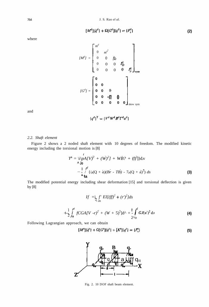
2.2. Shaft element
Figure 2 shows a 2 noded shaft element with 10 degrees of freedom. The modified kineticenergy including the torsional motion is [8]
= \i\pA[V)2 + (W)2] + WB? + (f)2]}d.v^ Jo
- / {/P(Q + a)(Br - TB) - 7P(Q + a)2) ds1 la
(3)
The modified potential energy including shear deformation [15] and torsional deflection is givenby [8]
If =i f' EI[(ff)2
*• Jo(r')2]ds
-- I fCGA[V -r)2 + (W + 5)2]d^ + -2^o
Following Lagrangian approach, we can obtain
(4)
(5)
q, B q.
q. a Uff qtt
Fig. 2. 10 DOF shaft beam element.

Lateral response of geared rotors 765
where
{q)T = {q\qi[W] = [M\] + [M\] + [Ml]
[M\] =
[MR] =
s],+<D2[GS]2
and
\2EI<b =
K'GAPThe elements of the above matrices are given in the Appendix.
2.3. Incremental stiffness due to axial torque
The shear angles of the shaft element are V - F and W + B. Following Zorzi andNelson [13], the total virtual work of the axial torque on the bending curvatures is
8W= f(TTSB'-TBSr')dsJo
In the above Equation (6), the axial torque is time dependent and varies from element to el-ement. For /th element it is given as
Equation (6) can now be rewritten as
(7)
where the shape function matrix is given by
0 -Ni N2 0 0 0 -N3 N4 0 0/V, 0 0 iV2 0 iV, 0 0 N4 0
with
I(.v
The incremental stiffness matrix [ A -̂j] due to the axial torque is then obtained from Equation (7)as

766 J. S. Rao el at.
(8)
which is defined in the Appendix.
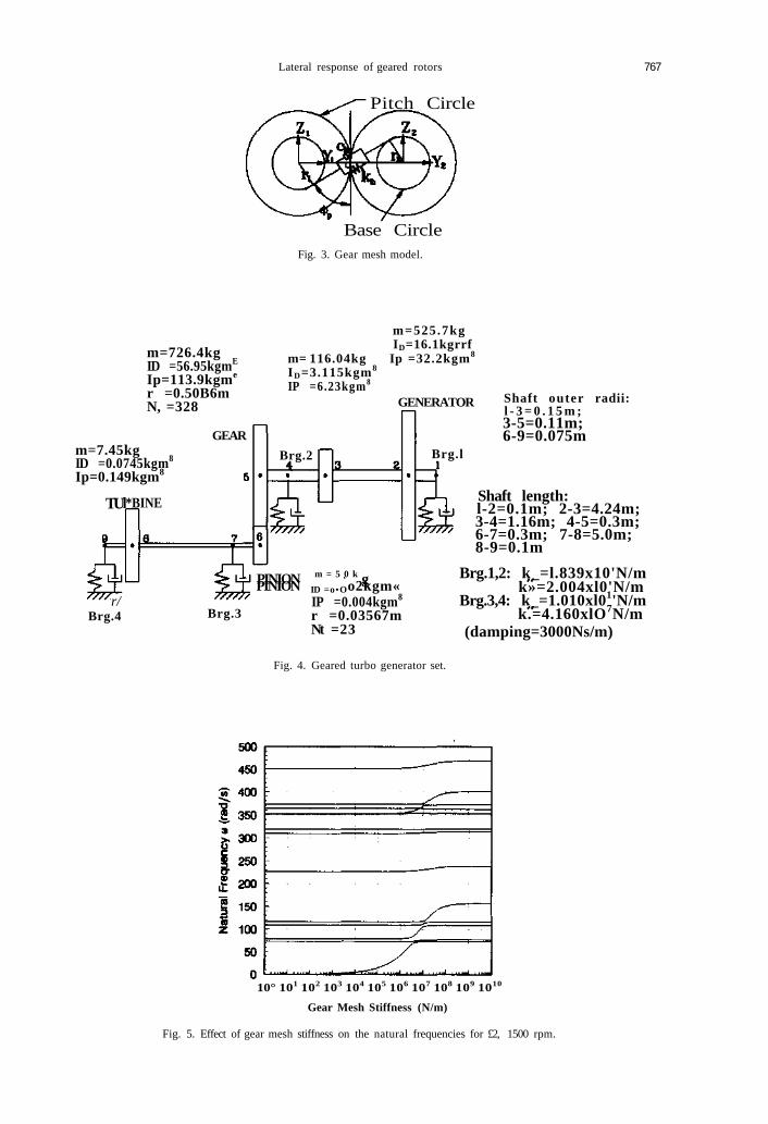
2.4. Gear mesh
Figure 3 shows a gear pair, in which the teeth are replaced by equivalent stiffness and damp-ing along the pressure line. In the present model, damping is not taken into account. The gearmesh force is
Fh = *h[( A ~ 1) sin 0p + (PFf - W*) cos </>p - (r,af + r2af)]
On gear 1, the components of the gear mesh force can be expressed as
Fhvi = F h s i n 0 p =kh[-S2-SC 0 0 - r , 5 S2 SC 0 0 - r2S]{qs
FhWi = Fh cos 4>p = kh[-SC -C2 0 0 - r, C SC C2 0 0 - n
(9)
0 0 - ry 0 0 - (10)
Similarly, on gear 2,
Fh\2 = —Ft) sin</>p = kh[S~ SC 0 0 r\S — S~ — SC 0 0
Fm2 = -Fh cos 4>p=kb[SC C2 0 0 rxC - SC - C2 0 0 r2C]{qs)
Th2 = r2Fh = kh[-r2S - r2C 0 0 - rxr2 r2S r2C 0 0 - r2,]^8}
For the gear pair, we can obtain
|~[Mf]
where
[Mf ] = [M*]
[Gf] = [Gf]
SC 0 0 n S - S 2 -SC 0 0 r2S
C2 0 0 rxC -SC -C2 0 0 r2C
0 0 0 0 0 0 0 0 0
0 0 0 0 0 0 0 0 0
(11)
(12)
s 2
SC
0
0r\S rxC 0 0 r l
-S2 -SC 0 0 -riS
-SC -C2 0 0 -r\C
-r{S -rxC 0 0 rxr2
XS S2 SC 0 0 -r2S'
SC C2 0 0 -nC
0
0
T S
0
0
0
0
0
0
0
0
0
0
/ " 1 /••)
0
0
-nS
0
0
-r-,C
0
0
0
0
0
0
0
0
and
Lateral response of geared rotors
Pitch Circle
767
Base CircleFig. 3. Gear mesh model.
m=726.4kgID =56.95kgmE
Ip=113.9kgme
r =0.50B6mN, =328
m=7.45kgID =0.0745kgm8
Ip=0.149kgm8
TU*BINE
r/Brg.4
GEAR
m=525.7kgID=16.1kgrrf
m= 116.04kg Ip =32.2kgm8
ID=3.115kgm8
IP =6.23kgm8
GENERATOR
Brg.2
Brg.3
Brg.l
Shaft outer radii:l - 3 = 0 . 1 5 m ;3-5=0.11m;6-9=0.075m
PINION m = 5 0 k gPINION ID =o.Oo2kgm«IP =0.004kgm8
r =0.03567mNt =23
Fig. 4. Geared turbo generator set.
Shaft length:l-2=0.1m; 2-3=4.24m;3-4=1.16m; 4-5=0.3m;6-7=0.3m; 7-8=5.0m;8-9=0.1m
Brg.1,2: k_=l.839x10'N/mk»=2.004xl0'N/m
Brg.3,4: k_=1.010xl01'N/mk.=4.160xlO7N/m
(damping=3000Ns/m)
10° 101 102 103 104 105 106 107 108 109 1010
Gear Mesh Stiffness (N/m)
Fig. 5. Effect of gear mesh stiffness on the natural frequencies for £2, 1500 rpm.

768 J. S. Rao et al.
500
450
400
I 3 5 0~ 3003
250
200—
I 150100
500
0 50 100 150 200 250 300 350 400 450 500Spin Speed a (rad/s)
Fig. 6. Campbell diagram for geared turbine generator.
/r ' /
- . - r - - ! i / )—
/ /
t.,
/ . . /' • ; Z _
1 i * •
. i...! .,.y —i—
Table 1. Coupled natural frequencies and response spectra in rad/s of the sys-tem gear mesh stiffness 108 N/m, fi, = 1500 rpm = 157.08 rad/s
Modenumber
123456789
10111213
Naturalfrequency
73.177.2
108.5116.0150.5236.8313.5319.6353.5362.9371.9396.6466.2
Lateralresponsespectra
—108.75116.8151.03
—314.15
——
362.49———
Torsionalresponsespectra
—
——
151.03———
———
465.2
H8
0 2 4 6
Time/period
Fig. 7. Two phase short circuiting torque.

Lateral response of geared rotors 769
1.5
{£ 0.5
I °5 -0.5
-1 -
-1.5 ^0
(b)
r-
: :
- • s . s
MMUflWim8 104 6
Time/period
Fig. 8. (a) Generator shaft torque, (b) Turbine shaft torque.
2.5. Bearing
The strain energy and the dissipation function of an eight coefficient bearing can be written as
(13)
2.6. System equations of motion
Equations (2), (5), (8), (12) and (13) can be combined for the system to give
= 0 (14)
3. SHORT CIRCUITING TORQUE
The short circuiting torque 7"sc= TgL+ Ts consists of two components[12]:

770 J. S. Rao el al.
(b)--Y-direction—Z-direction
0.01
0.005
0
-0.005
•O.01
-0.0152 4 6
Time/period
8 10
Fig. 9. (a) Lateral response at bearing No. 1. (b) Lateral response at pinion.
3.1. Air gap torque
This torque is given by
= Tnmd e"5" sin cot (15)
which dominates during the sub-transient period. In the above m is the oscillating moment, Tn
is the nominal torque and a is the sub-transient saliency constant.
3.2. Armature torque
The armature torque which acts at twice the rotational speed is given by
Js = Tnms e~p' sin lent (16)
which dominates during the transient period. In the above fi is the transient saliency constant.

Lateral response of geared rotors
(a)
771
4 6
Time/period
4 6
Time/period
Fig. 10. (a) Torsional response at bearing No. 1. (b) Torsional response at gear
The system Equation (14) can now be modified to include the excitation torque
[M\{q\ + [Q,[G] + [C]][q} + ([K\ - [KT]){q] = {F\ (17)
4. TURBO-ALTERNATOR EXAMPLE
Based on the finite element formulation in Section 2, a computer program is developed usingIMSL library to determine the natural frequencies, critical speeds and the response due to shortcircuiting torque given in Section 3.
Figure 4 shows a typical example of a turbo-alternator rotor system. The generator, rotor 1,runs at Q, = 1500 rpm. The Young's modulus of the shaft material is E = 207 GPa, shear mod-ulus is G = 79.5 GPa and the density of the material is 7800 kg/m3. The transmission unitbetween the generator rotor 1 and turbine 2, is a simple spur gear pair with gear ratio = 328/23and the pressure angle 22.5°. All the other data except the gear mesh stiffness for the system isshown in the figure.

772
(8E-005
7E-005
6E-005
5E-005
4E-005
3E-005
2E-005
1E-005
0
J S. Rao et al.
a)
-
-
-
-
-
- I
H , 1 A- .0.5 1 1.5 2 2.5
Frequency (x1500rpm)
0.004
3
0.5 1 1.5 2 2.5 3
Frequency (x1500rpm)
Fig. 11. (a) Frequency spectrum of y direction response at bearing No. 1 for £h=108 N/m. (b)Frequency spectrum of v direction response at pinion for kh= 108 N/m.
4.1. Effect of gear mesh stiffness
The natural frequencies of the system at the operational speed are obtained for differentvalues of gear mesh stiffness and shown in Fig. 5. The natural frequencies are affected for thegear mesh stiffness in the region 104 to 108 N/m, particularly around 107 N/m. In the analysisthat follows, three gear mesh stiffness values are chosen.
4.2. Gear mesh stiffness 108 N/m (bending critical speed close to spin speed)
The Campbell diagram for this case is shown in Fig. 6. The natural frequencies at the oper-ational speed are given in Table 1.
From the above table, it can be seen that there are several frequencies close to the spin speedand half spin speed and 2 times the spin speed.
The normalized short circuit torque
T1 .se-
denned in Section 3 is shown in Fig. 7 for Tn = 6366.2 Nm, m.d= 12.353, ms = 0.5, a = 33.97

Lateral response of geared rotors
(a)
773
U.UU1Z
0.001
0.0008
0.0006
0.0004
0.0002
n
Ij
0 0.5 1 1.5 2 2.5
Frequency (x1500rpm)
(b)0.0006
0.0005
0.0004
0.0003
0.0002
0.0001
0 0.5 1 1.5 2 2.5 3
Frequency (x1500rpm)
Fig. 12. (a) Frequency spectrum of torsional response at bearing No. 1. (b) Frequency spectrum of tor-sional response at gear.
and /? = 5.45. The shaft torque due to this excitation is given in Fig. 8(a) and Fig. 8(b). Thegenerator rotor experiences torque values which are five times, or more, that of the nominal tor-que and the turbine rotor pulsating torque magnitude is the same as the nominal torque.
The lateral response (y direction) at the right bearing 1 of the generator is found to be mini-mum as shown in Fig. 9(a) and the pinion on the turbine rotor experiences maximum responseas shown in Fig. 9(b). It may be noted that the response shown in Fig. 9(a) is only for 10periods of time and that it is not as unstable as it may appear to be. For clarity only 10 periodsof time is shown and if one takes into account, say, 50 periods of time the signal is clearly seento be stable. The torsional response is maximum again at the bearing 1 as shown in Fig. 10(a)and the minimum response in torsion is experienced by the gear on the generator as shown inFig. 10(b).
FFT analysis is made for all the response signals starting from time t = 0 (signal duration3.12 s corresponding to 78 revs of rotor 1 is used) given in Figs 9 and 10. The results are shownin Fig. 11 (a) for the lateral response of bearing 1 and in Fig. ll(b) for the lateral response ofthe pinion. For the torsional response the results are given in Fig. 12(a) for bearing 1 and inFig. 12(b) for the gear. These frequency components are also shown in Table 1. The lateral re-sponse has shown frequency components to be 108.75, 116.8, 151.03, 314.15 and 362.49 rad/s

774 J. S. Rao el al.
(a)
H--+ - —
(b)
Fig. 13. (a) Mode shape of natural frequency 150.5 rad/s at Q| = 1500 rpm. (b) Mode shape of naturalfrequency 466.2 rad/s £1, = 1500 rpm.
0 50 100 150 200 250 300 350 400 450 500
Spin Speed 0 (rad/s)
Fig. 14. Campbell diagram for geared turbine generator.
Table 2. Coupled natural frequencies and response spectra in rad/s of the sys-tem gear mesh stiffness 107 N/m, Cl, = 1500 rpm
Modenumber
123456789
10111213
Naturalfrequency
73.076.3
105.7112.2117.9231.0311.9319.3354.3363.9370.0374.6457.6
Lateralresponsespectra
72.576.5
105.7112.8118.8
————————
Torsionalresponsespectra
76.5104.7112.8118.8
_..
—
——
457.1

Lateral response of geared rotors 775
10 20 30 40
Time/period
50 60
10 20 30
Time/period
40 50
Fig. 15. (a) Lateral response in y direction at pinion for kh= 107 N/m. (b) Torsional response at gearfor A.h=107 N/m.
and the torsional response has shown two predominant frequencies 151.03 and 465.2 rad/s. Inboth the cases, the response is very predominant at 151.03 rad/s, which is close to the naturalfrequency 150.05 rad/s. Thus, the rotor without any unbalance (perfectly balanced) exhibits pre-dominant lateral amplitudes of whirl at its critical speed when the torsional excitation frequencyis close to it. The severity is significant at the gear pair and may be harmful for the running ofthe machine. This can be observed from the mode shape at 151.03 rad/s given in Fig. 13(a). Thetorsional response is predominant at 465.2 rad/s, since the mode shape at 466.2 rad/s is the fun-damental torsion mode as can be seen in Fig. 13(b). It may be noted that the response spec-trums do not exhibit any synchronous components with spin speed, since the excitation istransient in nature. All the response spectra are around one or more of the natural frequenciesonly.
The response of the system is obtained with the incremental stiffness matrix set to zero, theresults show no visible difference when compared with those above in Figs 9 and 10 which takeinto account the incremental stiffness. It may be said here that the incremental stiffness termseffect is practically negligible even under short circuiting conditions.

776 J. S. Rao el al.
0.5 1 1.5 2 2.5
Frequency (xi500rpm)
(b)0.0007
0 0.5 1 1.5 2 2.5 3
Frequency (x1500rpm)
Fig. 16. (a) Frequency spectrum of y direction response at pinion for kh= 107 N/m. (b) Frequency spec-trum of torsional response at gear for kh = 107 N/m.
500
450
400
350
300
250
200
150
100
50 L / X
7
Fig.
0 50 100 150 200 250 300 350 400 450 500
Spin Speed 0 (rad/s)
17. Campbell diagram for geared turbine generator.

Lateral response of geared rotors
Table 3. Coupled natural frequencies and response spectra in rad/s of the sys-tem gear mesh stiffness 106 N/m, Qi = 1500 rpm
777
Modenumber
123456789
10111213
Naturalfrequency
42.773.479.6
109.1116.4227.2309.9319.1353.4354.2364.1373.1452.3
Lateralresponsespectra
42.3———
———
————
Torsionalresponsespectra
42.3__.——
—
453.1
10 20 30 40
Time/period
50
20 30
Time/period
Fig. 18. (a) Lateral response in r direction at pinion for />,, = 10'' N/m. (b) Torsional response at gearfor kh= 106 N/m.

778
(0.0018
0.0016
0.0014
=• 0.0012
| 0.001
- 0.0008o
| 0.0006
0.0004
0.0002
0
J. S. Rao et al.
a)
-
-
-
v , , , ,0.5 1 1.5 2 2.5
Frequency (xi500rpm)
0.5 1 1.5 2 2.5 3
Frequency (xi500rpm)
Fig. 19. (a) Frequency spectrum of y direction response at pinion for A:h = 10** N/m. (b) Frequency spec-trum of torsional response at gear for kh = 106 N/m.
4.3. Gear mesh stiffness I07 N/m (no critical speed near the spin speed)
The Campbell diagram for this case is shown in Fig. 14. The natural frequencies at the oper-ational speed are given in Table 2.
The lateral response (y direction) at the pinion is shown in Fig. 15(a) and the torsional re-sponse for the gear on the generator as shown in Fig. 15(b).
FFT analysis is made for the response as in the previous case 4.1. The significant responsespectra for the pinion in bending and for the gear in torsion are given in Fig. 16(a) andFig. 16(b), respectively. The corresponding frequency components are also shown in Table 2.The lateral response has predominant components at 104.7 and 112.8 rad/s natural frequencies.In the present case, there is no natural frequency near to the running speed, and the response atthe 104.7 and 112.8 rad/s is about half of that at 151.03 in Fig. ll(b). The response at 457.1rad/s in torsion in Fig. 16(b) is predominant and is four times that in Fig. 12(b). In the previouscase of Table 1, there is a resonant frequency quite close to the running speed and most of theenergy is dissipated in the mode 150.05 rad/s, whereas in the present case, there is no resonantcondition near the operating speed and therefore the energy is dissipated in the first torsionmode and hence increased response at the frequency 457.1 rad/s.

Lateral response of geared rotors 779
4.4. Gear mesh stiffness l(f Njm (torsional critical speed close to 3 per rev)
The Campbell diagram for this case is shown in Fig. 17. The natural frequencies at the oper-ational speed are given in Table 3.
The lateral response (y direction) at the pinion is shown in Fig. 18(a) and the torsional re-sponse for the gear on the generator as shown in Fig. 18(b).
The significant response spectra for the pinion in bending and for the gear in torsion aregiven in Fig. 19(a) and Fig. 19(b), respectively. The corresponding frequency components arealso shown in Table 3. The lateral response has a predominant component at 42.3 rad/s naturalfrequency which is very close to one-fourth of the operational speed. In this case also, there isno natural frequency near to the running speed. The response at 453.1 rad/s in torsion, which is2.88 times the spin speed (closer to 3 per rev), in Fig. 19(b) is predominant and is higher thanthat in Fig. 16(b) for case 4.3, even though 457.1 rad/s is 2.91 times the spin speed (more closerto 3 per rev). This can be attributed to the fact that there is only one frequency 42.3 rad/s atwhich the rest of the energy is dissipated in the present case 4.4 as compared to five other fre-quencies in the case 4.3.
(a)1500
1000
500
0
-500
-1000
-1500 u
0 50 100 150 200 250 300 350 400
Time/period
0 50 100 150 200 250 300 350 400
Time/period
Fig. 20. (a) Lateral response in y direction at gear for kh = 0 N/m, Tn = 2,546,480 Nm at fi, = 104.7 rad/s. (b) Torsional response at gear for kh = 0 N/m, Tn = 2.546,480 Nm at fli = 104.7 rad/s.

780 J. S. Rao et at.
4.5. Case 4.2 with k^ = Q with a hypothetically large torque
In all cases 4.2-4.4 above, the spin speed is far lower than that of the first torsion mode.Therefore, the torsional response is almost rigid body mode with no difference or very littledifference between the torsional amplitudes from one station to another. Hence, the torquevalues
GJ <—-(a,-+i - a , )
are almost negligible even under the short circuiting conditions. In order to study the influenceof the incremental stiffness due to axial torque, the rotor system in Fig. 4 is modified by makinggear mesh stiffness equal to zero, i.e. the two rotors are decoupled and that there is no coupledbending-torsion motion. A coupling is introduced at station 3 to lower the torsional mode. Theleft half of the coupling has /p = 2.43 kgm2, 1^= 1.215 kgm2 and m — 54 kg and the right half7P = 3.8 kgm2, 7D= 1.9 kgm2 and m = 62.4 kg with a torsional stiffness 4.75 x 10⁵ Nm/rad. Thetorsional natural frequency is now obtained as 104.7 rad/s. The excitation torque is given to thegenerator as in the previous cases and the rotor is run at 104.7 rad/s spin speed so that the tor-que values will be very large in the shaft sections. For a nominal value of the torque,Tn = 6366.2 Nm as in the previous cases and an initial disturbance V = 0.0002 m,W = 0.0001 m V= 0.002 m/s, ^=0.001 m/s at stations 2 and 5, the lateral response is found tonegligible. However, for a very large value of torque, say, 2,546,480 Nm, the lateral responsebecomes unstable with large amplitudes of whirl as shown in Fig. 20(a) and Fig. 20(b) and thetorsional response remains stable, though it is very large in view of the excessive torque appliedto the system. The instability in lateral vibration occurs for very large value of torques when theelements of incremental stiffness matrix become sufficiently larger than the conventional stiffnessmatrix elements making the system to have an overall negative bending stiffness. In otherwords, for large values of torques that may be encountered in practice, like a short circuit tor-que, the incremental stiffness may be neglected.
CONCLUSIONS
The lateral response of rotors under torsional excitation is studied. In the presence of geartransmission units, the lateral response due to short circuit excitation torques is shown to bevery significant. The severity is very high when a fully balanced rotor is run at a bending criticalspeed under the action of a short circuit torque. Even if the rotor has no critical speed close byto the running speed, the lateral response at a multiple of the spin speed as well as torsional re-sponse in the fundamental mode are very large. The influence of incremental bending stiffnessdue to axial torque is found to be insignificant.
Acknowledgements—The authors are very thankful to the National Science Council of Taiwan for the grant NSC 84-2212-E-194-001 to carry out this project. One of the authors of this paper, Professor J. S. Rao would like to thankNational Science Council of Taiwan for the award of the Research Chair at the National Chung Cheng University andto BHEL and the Indian Institute of Technology, Delhi for having given leave from the BHEL Chair position in Indiaduring 1994-1996.
REFERENCES1. Rao, J. S., in Rotor Dynamics, 3rd edn. New Age International Publishers, London, 1996.2. Lalanne, M. and Ferraris, G., Rotor Dynamics Prediction in Engineering, Wiley, New York, 1990.3. Lund, J., J. Mechanical Design, Trans ASME, 1978, 100, 535.4. Iida, H., Tamura, A., Kikuchi, K. and Agata, H., BullJSME, 1980, 23(186), 2111.5. Kahraman, A., Nevzat, Ozguven H., Houser, D. R. and Zakrajsek, J. J., J. of Mechanical Design, Trans ASME,
1992. 114, 507.6. Shiau, T. N. and Hwang, J. L., J. q/ Engineering for Gas Turbines and Power, Trans ASME. 1993, 115, 209.7. Shiau, T. N., Chou, Y. W., Chang, J. R. and Nelson, H. D., ASME 94-GT-355, 1994.8. Rao, J. S.. Chang, J. R. and Shiau, T. N., DE-Vol. 84-2, 1995 ASME Design Engineering Technical Conferences. 2,
Part B, 1995.9. Saling, K. H. and Schwinder, Th. CIGRE Report, 1966, p. 138.
10. Concordia, C, Synchronous Machine Theory and Performance. Wiley, New York, 1956.11. Rao, J. S., Rao, D. K. and Bhaskara, Sarma K. V., GOT/'. /. Mech. E. Cambridge, England, 1980, p. 271.12. Rao, J. S., Mech. Much. Theory, 1992, 27(3), 283.13. Zorzi, E. S. and Nelson, H. D., ASME J. of Mech. Des.. 1980, 102, 158.

Lateral response of geared rotors 781
14. Nezat, Ozguven H. and Houser, D. R., J. Sound Biv., 1988. 121(3), 383.15. Nelson, H. D., ASME J. of Mech. Des., 1980. 102, 793.
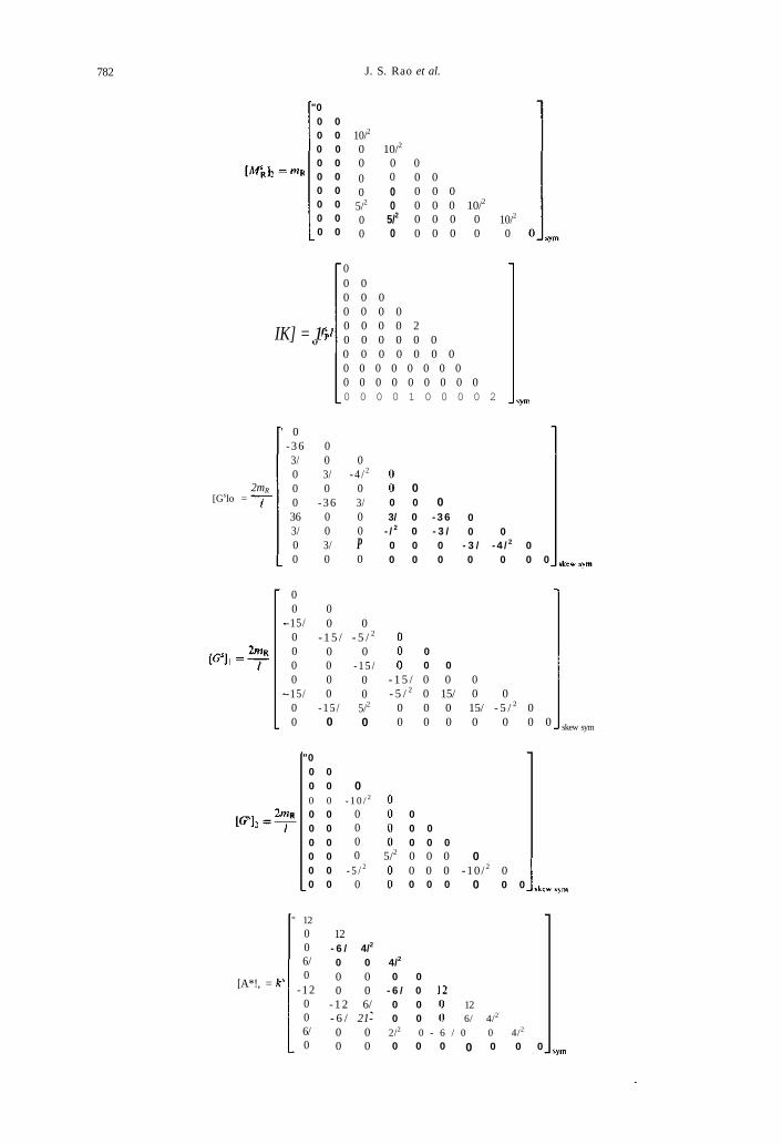
APPENDIX A
The shaft element matrices are:
[M\}0 = mTT
31200
44/0
10800
- 2 6 /0
5880 588
312-44/
000
10826/00
8/2
000
- 2 6 /- 6 / 2
00
0 - 7 7 / 14/2
77/ 00 0
252 00 2520 63/
- 6 3 / 00 0
T
2800
000
- 6 3 /-14/ 2
00
2800 - 3 5 /
35/0
14000
- 3 5 /0
mR
mR
" 36003/0
-36003/0
" 000
- 1 5 /0000
- 1 5 /0
000
14035/00
36- 3 /000
-36- 3 /00
015/0000
15/00
7/2
000
- 3 5 /7/2
00
4/2
0003/
- / 2
00
5/2
000
- 1 5 /- 5 / 2
00
8/2
026/00
- 6 / 2
0
14/2
063/00
-14/2
0
7/2
035/00
- 7 / 2
0
4/2
0- 3 /00
-P0
5/2
015/00
- 5 / 2
0
000000
000000
000000
000000
000000
31200
- 4 4 /0
58800
- 7 7 /0
28000
- 3 5 /0
3600
- 3 /0
000
15/0
31244/00
58811100
28035/00
36
8/2
00
14/2
00
7/2
00
3/ 4/2
00
015/00
8/2
0 0_ sym
-
14/2
0 0
-
7/2
0 0_
- i
0 4/2
0
5/2
00
0 0_
5/2
0 0
sym
sym
782 J. S. Rao et al.
"00 00 00 00 00 00 00 00 00 0
10/2
0 10/2
0 000
05/2
00
00
5/2
0
00 00 0 00 0 0 10/2
0 0 0 00 0 0 0
10/2
0
IK] = 1
00 00 0 00 0 0 00 0 0 0 20 0 0 0 0 00 0 0 0 0 0 00 0 0 0 0 0 0 00 0 0 0 0 0 0 0 00 0 0 0 1 0 0 0 0 2
[Gslo =2mR
' 0- 3 63/000363/00
003/0
- 3 6003/0
0- 4 / 2
03/00P0
000 0
3/ 0 - 3 6- / 2 0 - 3 /0 0 00 0 0
00 0
- 3 / - 4 / 2 00 0 0 0
00
-15/0000
-15/00
00 0
- 1 5 / - 5 / 2
0 0- 1 5 /
00
5/2
000
- 1 5 /0 0
00 0
- 1 5 / 0 0- 5 / 2 0 15/
0 0 00 0 0
00 0
15/ - 5 / 2 00 0 0 0 skew sym
"00 00 0
0 00 00 00 00 00 0
00 0 - 1 0 / 2
0000
- 5 / 2
0
00 00 0 0
5/2 0 0 0 00 0 0 -10 / 2 00 0 0 0 0 0
[A*!, =
" 12006/0
-12006/0
12- 6 / 4/2
0 0 4/2
0 00 0
- 1 2 6/- 6 / 21-0 00 0
0 0- 6 / 00 00 0
126/ 4/2
2/2 0 - 6 / 0 0 4/2
0 0 0 0 0 0 0

Lateral response of geared rotors 783
[**], = k"
00 00 00 00 00 00 0
00 00 0 0
0 0 -I2 0 0 0 0 I2
0 0 0 -I2 0 0 0 0 I2
0 0 0 0 0 0 0 0 0 0
and
[*Ti]l = T
00 00 0 00 0 0 00 0 0 00 0 0 00 0 0 00 0 0 00 0 0 0
00 00 0 00 0 0 0
0 0 0 0 - 1 0 0 0 0 1
00<*0000
00
000
K$0000
0
K$00i
6
00
- i + IK^' 0
0
#<„- i
0"00
-Kit,
00
0000000
, 0
00
00
-K9
0000
K®00
000
0000
KQ
0
—A"o
00
\ - K<*
0K<t>
00
_ |0"
0-K®
-k + l&' 0
00
Kp1T
60
00
» 00000000
where
840(1 +<D)-
120/(1+<D)2
k* =
K'GAP
El