Embed Size (px)
Citation preview

The world is movemenT
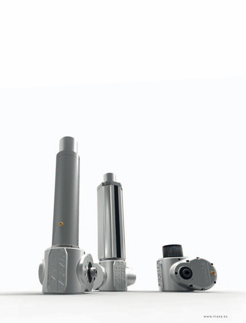
04LINEAR ACTUATORS WITH INTEGRATED REDUCTION AND COMPACT GEARBOX
FHM Series: Steel tubeAHM Series: Aluminum tube


“WE HAVE A STRATEGIC PLAN. IT'S CALLED DOING THINGS.”HERB KELLEHERSOUTHWEST AIRLINES

148
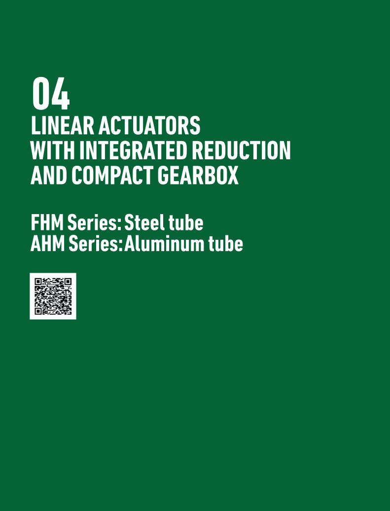
NIASA FHM/AHM Series electro-mechanical actuators have evolved from the FM/AM Series, aimed at specific requirements in the solar energy generation sector (photovoltaic, thermo-solar, etc.). They can also be used in any other kind of application with demanding environmental conditions.
The gearbox is round and not cubic, and the input shaft offers the possibility to connect directly to any type of drive. Additionally, the D variant includes a second reduction, thus avoiding the use of reducers in solar tracking or similar applications, where very slow advance speeds are required.
Their main advantages against other systems, such as pneumatic or hydraulic cylinders, are the following:
… Greater movement and positioning precision.
… Greater safety, due to their irreversibility in many configurations (ask NIASA) and/or the incorporation of different braking devices.
… Superior energy efficiency, as their parts offer high/very high performance, especially with the ball screws, low transmission ratios and high speeds.
… Easier and faster assembly, since hydraulic or pneumatic groups are not required, just an electric motor on the unit itself.
… Greater reliability and duration, and less maintenance, due to the mechanical robustness and construction simplicity.
… Possibility to operate in multiple positions.
… Lower size for the same load capacity.
… …
The screw supports also characterized for offering an extensive range of:
… Axial load capacities, from 5 kN up to 250 kN.
… Advance speeds, depending on the screw pitch and gearbox. Three possible reductions per actuator size are offered, from 4:1 up to 160:1.
… Trapezoidal and ball screws, depending on the performance required, precision of movement and positioning, etc.
… Fastening accessories and elements, for optimal adaptation.
… Control and safety systems (mechanical/inductive limit switches, absolute/incremental encoders, etc.).
… Materials and surface coverings, depending on the environmental conditions in which the unit will be installed.
… Two types of external sleeve for the stem
· Steel round tube.
· Aluminum extrusion profile.
· ...
Please do not hesitate to contact NIASA if you require FHM/AHM actuators (and their drive mechanisms) with specifications other than those covered in this chapter. The NIASA technical department will specifically develop the special units that best meet your requirements.
LINEAR ACTUATORS WITH INTEGRATED REDUCTION AND COMPACT GEARBOX. FHM SERIES: STEEL TUBE | AHM SERIES: ALUMINUM TUBE
INTRODUCTION
04
149
www.niasa.es
150
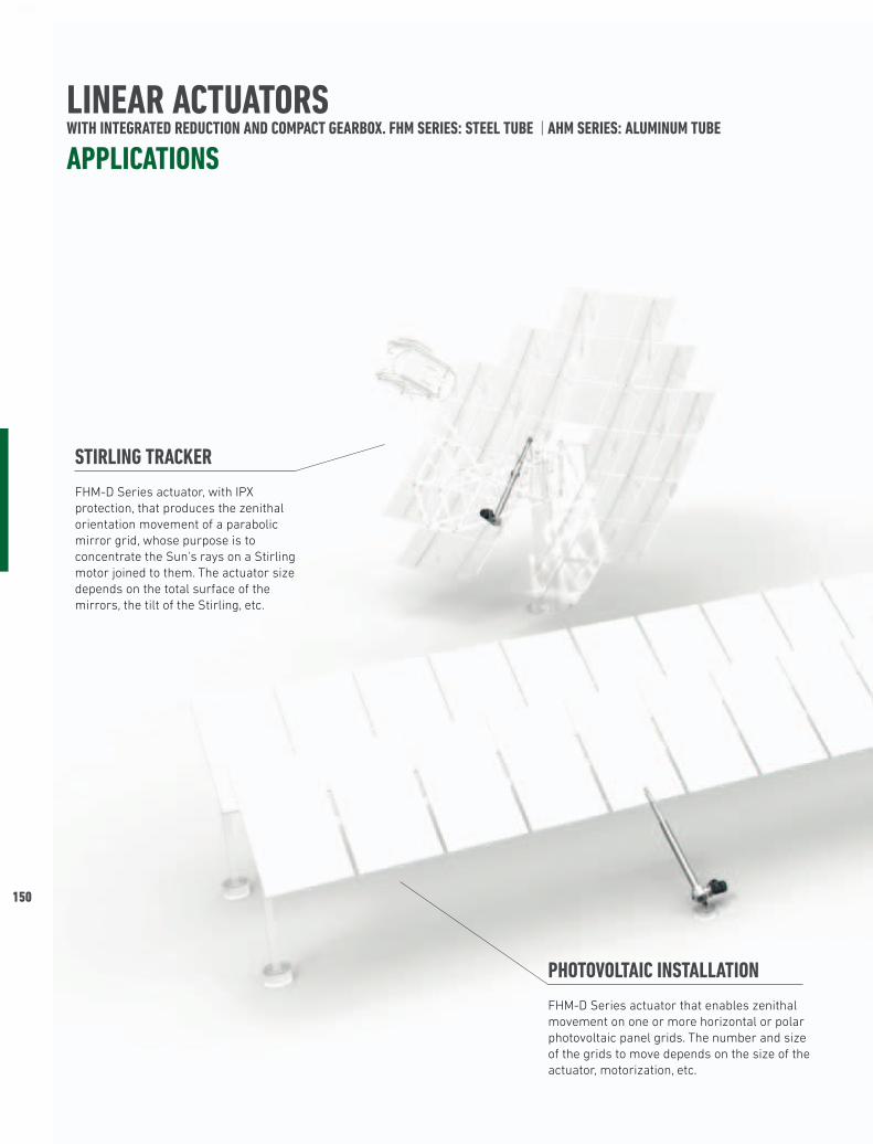
LINEAR ACTUATORS WITH INTEGRATED REDUCTION AND COMPACT GEARBOX. FHM SERIES: STEEL TUBE | AHM SERIES: ALUMINUM TUBE
APPLICATIONS
PHOTOVOLTAIC INSTALLATION FHM-D Series actuator that enables zenithal movement on one or more horizontal or polar photovoltaic panel grids. The number and size of the grids to move depends on the size of the actuator, motorization, etc.
STIRLING TRACKER FHM-D Series actuator, with IPX protection, that produces the zenithal orientation movement of a parabolic mirror grid, whose purpose is to concentrate the Sun's rays on a Stirling motor joined to them. The actuator size depends on the total surface of the mirrors, the tilt of the Stirling, etc.
04
151
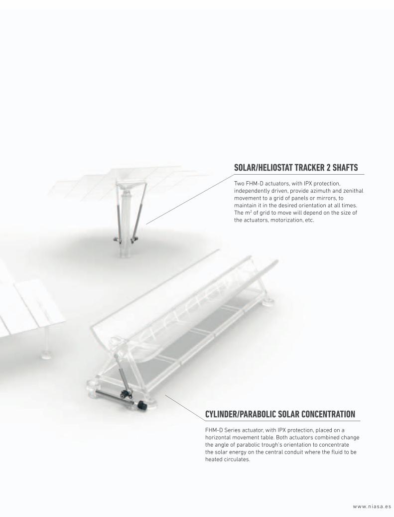
CYLINDER/PARABOLIC SOLAR CONCENTRATION FHM-D Series actuator, with IPX protection, placed on a horizontal movement table. Both actuators combined change the angle of parabolic trough’s orientation to concentrate the solar energy on the central conduit where the fluid to be heated circulates.
SOLAR/HELIOSTAT TRACKER 2 SHAFTS Two FHM-D actuators, with IPX protection, independently driven, provide azimuth and zenithal movement to a grid of panels or mirrors, to maintain it in the desired orientation at all times. The m2 of grid to move will depend on the size of the actuators, motorization, etc.
www.niasa.es
152
LINEAR ACTUATORS WITH INTEGRATED REDUCTION AND COMPACT GEARBOX. FHM SERIES: STEEL TUBE | AHM SERIES: ALUMINUM TUBE
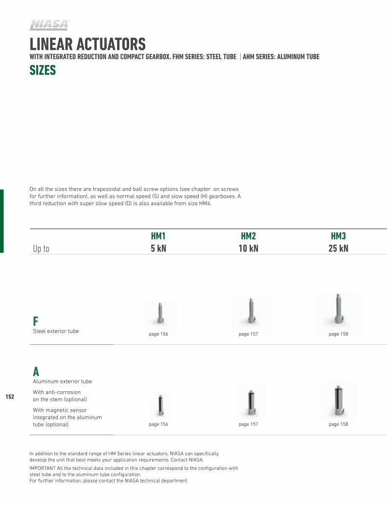
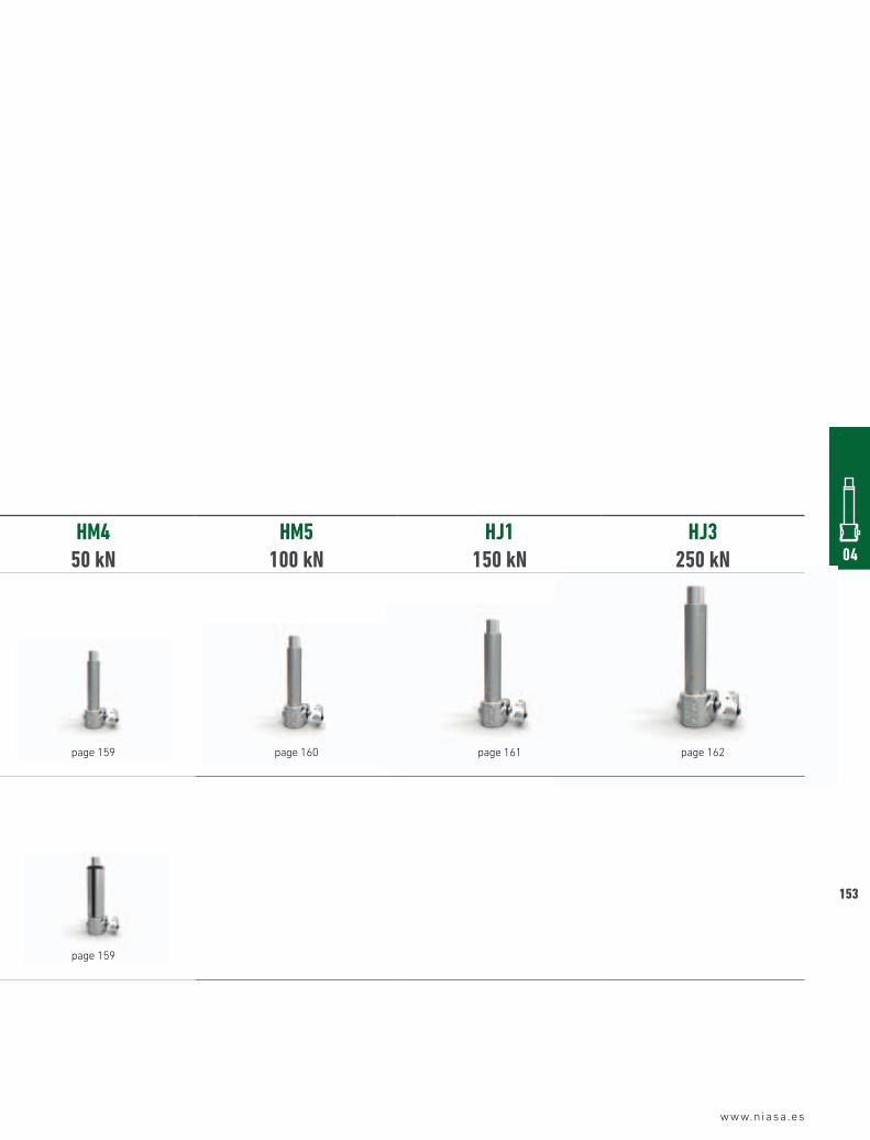
SIzES
On all the sizes there are trapezoidal and ball screw options (see chapter on screws for further information), as well as normal speed (S) and slow speed (H) gearboxes. A third reduction with super slow speed (D) is also available from size HM4.
In addition to the standard range of HM Series linear actuators, NIASA can specifically develop the unit that best meets your application requirements. Contact NIASA.
IMPORTANT All the technical data included in this chapter correspond to the configuration with steel tube and to the aluminum tube configuration. For further information, please contact the NIASA technical department.
Up toHM15 kN
HM210 kN
HM325 kN
HM450 kN
HM5100 kN
HJ1150 kN
HJ3250 kN
FSteel exterior tube page 156 page 157 page 158 page 159 page 160 page 161 page 162
AAluminum exterior tube
With anti-corrosion on the stem (optional)
With magnetic sensor integrated on the aluminum tube (optional) page 156 page 157 page 158 page 159
www.niasa.es
04
153
Up toHM15 kN
HM210 kN
HM325 kN
HM450 kN
HM5100 kN
HJ1150 kN
HJ3250 kN
FSteel exterior tube page 156 page 157 page 158 page 159 page 160 page 161 page 162
AAluminum exterior tube
With anti-corrosion on the stem (optional)
With magnetic sensor integrated on the aluminum tube (optional) page 156 page 157 page 158 page 159
154
LINEAR ACTUATORS WITH INTEGRATED REDUCTION AND COMPACT GEARBOX. FHM SERIES: STEEL TUBE | AHM SERIES: ALUMINUM TUBE
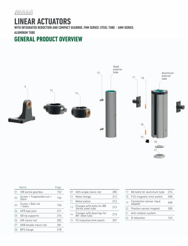
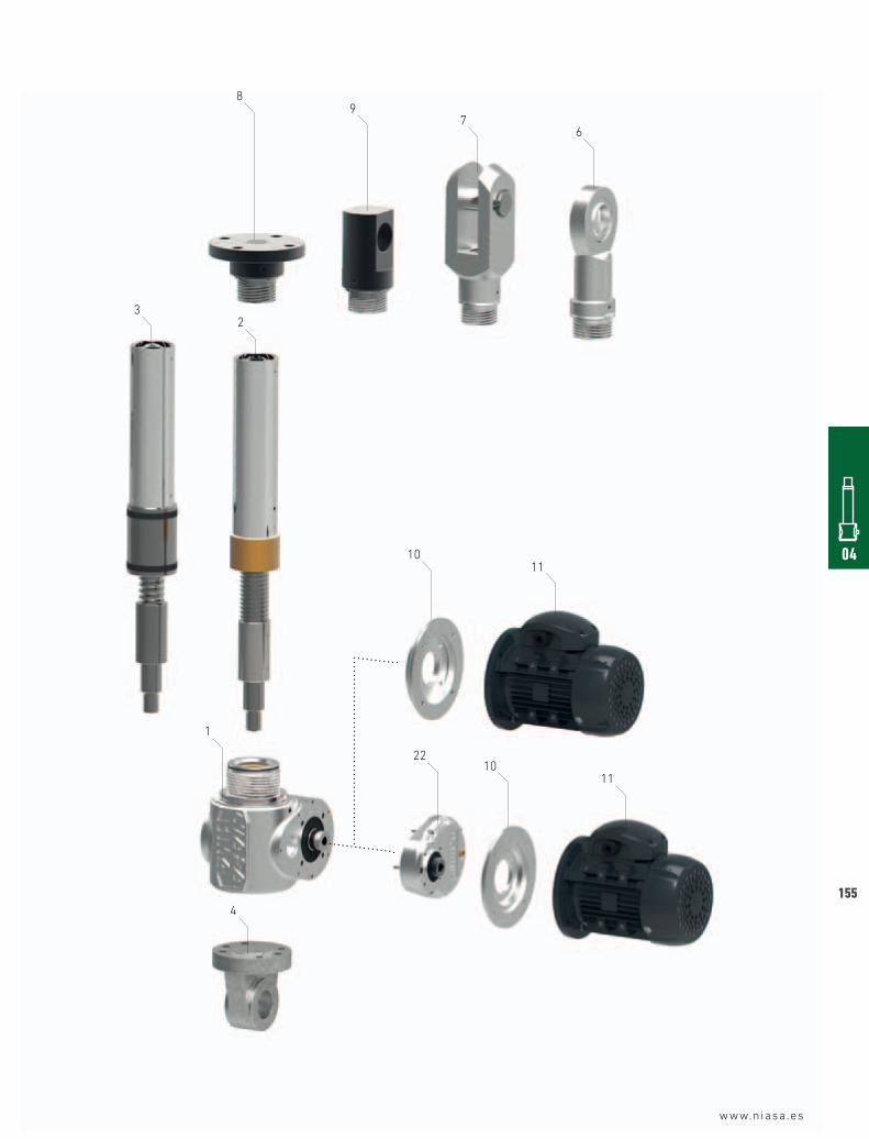
GENERAL PRODUCT OVERVIEW
01 HM series gearbox 152
02 Screw + Trapezoidal nut + Stem 156
03 Screw + Ball nut + Stem 156
04 HFR ball joint 271
05 SB tip supports 276
06 GIR clevis rod 282
07 GKB double clevis rod 281
08 BPS flange 278
09 GKS single clevis rod 280
10 Motor flange 312
11 Motorization 312
13 Flanges with bolts for BB Series steel tube 272
14 Flanges with bearings for BH steel tube 273
15 FCI inductive limit switch 307
17 BA bolts for aluminum tube 274
18 FCG magnetic limit switch 308
19 Connection sensor input adapter 308
20 Position sensor magnet 308
21 Anti-rotation system
22 D reduction 163
Name Page
5
Steel exterior tube Aluminum
exterior tube17
18
19
20
21
18
15
1314
04
155
www.niasa.es
8
3
10
1
2210
11
4
11
2
97
6
156
www.niasa.es
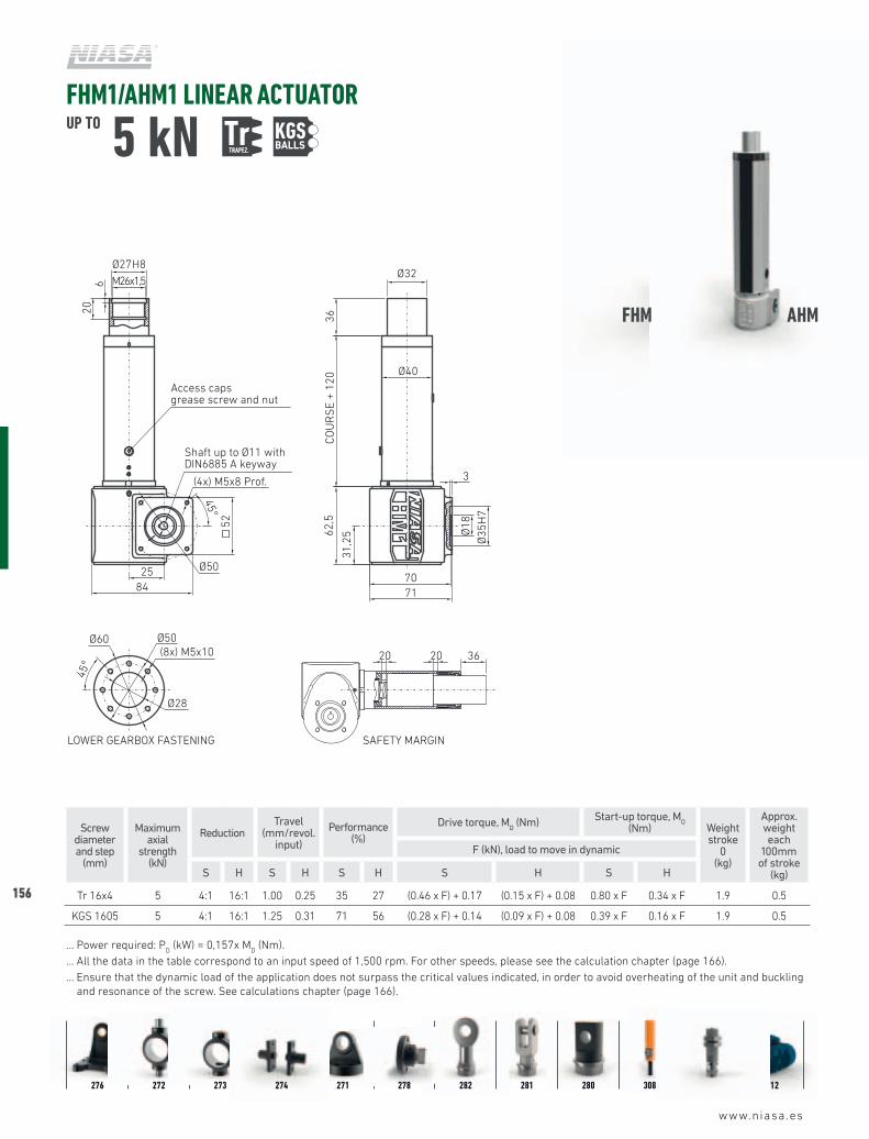
FHM1/AHM1 LINEAR ACTUATORUP TO 5 kN Tr
TRAPEZ. KGS
Screw diameter and step
(mm)
Maximum axial
strength (kN)
ReductionTravel
(mm/revol. input)
Performance (%)
Drive torque, MD (Nm) Start-up torque, M
O
(Nm) Weightstroke
0(kg)
Approx. weight each
100mm of stroke
(kg)
F (kN), load to move in dynamic
S H S H S H S H S H
Tr 16x4 5 4:1 16:1 1.00 0.25 35 27 (0.46 x F) + 0.17 (0.15 x F) + 0.08 0.80 x F 0.34 x F 1.9 0.5
KGS 1605 5 4:1 16:1 1.25 0.31 71 56 (0.28 x F) + 0.14 (0.09 x F) + 0.08 0.39 x F 0.16 x F 1.9 0.5
… Power required: PD (kW) = 0,157x M
D (Nm).
… All the data in the table correspond to an input speed of 1,500 rpm. For other speeds, please see the calculation chapter (page 166).... Ensure that the dynamic load of the application does not surpass the critical values indicated, in order to avoid overheating of the unit and buckling
and resonance of the screw. See calculations chapter (page 166).
276 272 273 274 271 278 282 281 280 308 307 312
FHM AHM
Shaft up to Ø11 withDIN6885 A keyway
Shaft up to Ø30 withDIN6885 A keyway
Shaft up to Ø24 withDIN6885 A keyway
70
HM1 HM2 HM3 HM4 HM5 HJ1 HJ3
LOWER GEARBOX FASTENING
220
(4x) M12x18 Prof.
Shaft up to Ø42 withDIN6885 A keyway
Shaft up to Ø34 withDIN6885 A keyway
Ø114 H8M110x2
6510
R80
Ø125
100
195
COU
RS
E +
360
Ø130
Ø150
Ø165(8x) M16x25
Ø100
45°
45°
97,5
Ø205
80300
Ø80
Ø14
0 H
7
260
= =
3 40
Access capsgrease screw and nut
20 20 110
SAFETY MARGINLOWER GEARBOX FASTENING
190
(4x) M10x16 Prof.
Ø100 H8M95x2
4510
R70Ø105
9518
0CO
UR
SE
+ 32
5
Ø110
Ø150
Ø45
Ø160(8x) M12x20
Ø90
45°
45°
Ø85
H7
16
268
71
220
3 30
Ø180
= =
Access capsgrease screw and nut
20 20 95
SAFETY MARGINLOWER GEARBOX FASTENING
160
(4x) M12x16 Prof.
Ø82 H8
M80x2
3710
R75
Ø100
6517
0CO
UR
SE
+ 30
0
Ø90
Ø115
Ø120(8x) M12x18
Ø80
45°
45°
85
= =
Ø145
71
226185
Ø40
Ø80
H7
252
Access capsgrease screw and nut
20 20 65
SAFETY MARGINLOWER GEARBOX FASTENING
144
(4x) M10x16 Prof.
Ø62 H8M60x2
359
R 65
Ø90
6714
0CO
UR
SE
+ 26
2
Ø70
Ø90
Ø 95
(8x) M10x16
Ø 62
45°
45°
22
70
3
= =
166
Ø35
Ø72
H7
196
Ø 125
63
Access capsgrease screw and nut
20 20 67
SAFETY MARGINLOWER GEARBOX FASTENING
110
(4x) M6x12 Prof.
Ø43 H8M42x2
309
Ø70
3795
COU
RS
E +
224
Ø50
Ø75
Ø70(8x) M8x16
Ø47
45°
45°
15
47,5
3
Ø98
45
125
Ø30
Ø62
H7
125
R40
Access capsgrease screw and nut
20* 20* 37
SAFETY MARGIN(*) If incorporating a KGM 3220 nut, the safety margin is 15 mm.LOWER GEARBOX FASTENING
100
Ø29 H8M27x2
267
Ø65
3689
COU
RS
E +
161
Ø35
Ø55
Ø65(8x) M6x12
Ø52
45°
45°
(4x) M5x10 Prof.
44,5
99
Ø85
112
32
Ø30
Ø60
H7
3
Access capsgrease screw and nut
20 20 36
SAFETY MARGINLOWER GEARBOX FASTENING
71
Ø27 H8
M26x1,5
206
Ø50
3662
,5CO
UR
SE
+ 12
0
Ø32
Ø40
Ø18
Ø50(8x) M5x10
Ø28
45°
45°
Ø35
H7
(4x) M5x8 Prof.
31,2
5
Ø60
25
3
7084
Access capsgrease screw and nut
20 20 36
SAFETY MARGIN
52
Shaft up to Ø20 withDIN6885 A keyway
Shaft up to Ø20 withDIN6885 A keyway
BALLS
www.niasa.es
04
157
Screw diameter and step
(mm)
Maximum axial
strength (kN)
ReductionTravel
(mm/revol. input)
Performance (%)
Drive torque, MD (Nm) Start-up torque, M
O
(Nm) Weightstroke
0(kg)
Approx. weight each
100mm of stroke
(kg)
F (kN), load to move in dynamic
S H S H S H S H S H
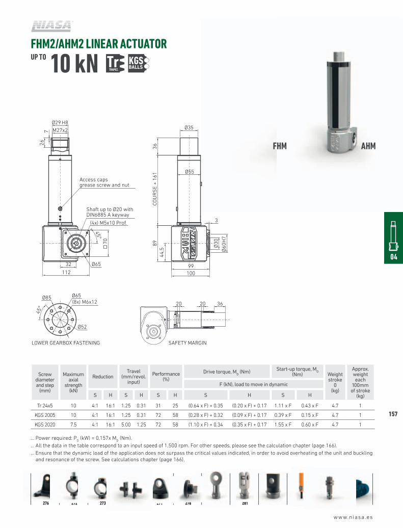
Tr 24x5 10 4:1 16:1 1.25 0.31 31 25 (0.64 x F) + 0.35 (0.20 x F) + 0.17 1.11 x F 0.43 x F 4.7 1
KGS 2005 10 4:1 16:1 1.25 0.31 72 58 (0.28 x F) + 0.32 (0.09 x F) + 0.17 0.39 x F 0.15 x F 4.7 1
KGS 2020 7.5 4:1 16:1 5.00 1.25 72 58 (1.10 x F) + 0.34 (0.35 x F) + 0.17 1.55 x F 0.60 x F 4.7 1
… Power required: PD (kW) = 0,157x M
D (Nm).
… All the data in the table correspond to an input speed of 1,500 rpm. For other speeds, please see the calculation chapter (page 166).... Ensure that the dynamic load of the application does not surpass the critical values indicated, in order to avoid overheating of the unit and buckling
and resonance of the screw. See calculations chapter (page 166).
FHM2/AHM2 LINEAR ACTUATORUP TO 10 kN Tr
TRAPEZ. KGS
276 272 273 274 271 278 282 281 280 308 307 312
FHM AHM
Shaft up to Ø11 withDIN6885 A keyway
Shaft up to Ø30 withDIN6885 A keyway
Shaft up to Ø24 withDIN6885 A keyway
70
HM1 HM2 HM3 HM4 HM5 HJ1 HJ3
LOWER GEARBOX FASTENING
220
(4x) M12x18 Prof.
Shaft up to Ø42 withDIN6885 A keyway
Shaft up to Ø34 withDIN6885 A keyway
Ø114 H8M110x2
6510
R80
Ø125
100
195
COU
RS
E +
360
Ø130
Ø150
Ø165(8x) M16x25
Ø100
45°
45°
97,5
Ø205
80300
Ø80
Ø14
0 H
7
260
= =
3 40
Access capsgrease screw and nut
20 20 110
SAFETY MARGINLOWER GEARBOX FASTENING
190
(4x) M10x16 Prof.
Ø100 H8M95x2
4510
R70Ø105
9518
0CO
UR
SE
+ 32
5
Ø110
Ø150
Ø45
Ø160(8x) M12x20
Ø90
45°
45°
Ø85
H7
16
268
71
220
3 30
Ø180
= =
Access capsgrease screw and nut
20 20 95
SAFETY MARGINLOWER GEARBOX FASTENING
160
(4x) M12x16 Prof.
Ø82 H8
M80x2
3710
R75
Ø100
6517
0CO
UR
SE
+ 30
0
Ø90
Ø115
Ø120(8x) M12x18
Ø80
45°
45°
85
= =
Ø145
71
226185
Ø40
Ø80
H7
252
Access capsgrease screw and nut
20 20 65
SAFETY MARGINLOWER GEARBOX FASTENING
144
(4x) M10x16 Prof.
Ø62 H8M60x2
359
R 65
Ø90
6714
0CO
UR
SE
+ 26
2
Ø70
Ø90
Ø 95
(8x) M10x16
Ø 62
45°
45°
22
70
3
= =
166
Ø35
Ø72
H7
196
Ø 125
63
Access capsgrease screw and nut
20 20 67
SAFETY MARGINLOWER GEARBOX FASTENING
110
(4x) M6x12 Prof.
Ø43 H8M42x2
309
Ø70
3795
COU
RS
E +
224
Ø50
Ø75
Ø70(8x) M8x16
Ø47
45°
45°
15
47,5
3
Ø98
45
125
Ø30
Ø62
H7
125
R40
Access capsgrease screw and nut
20* 20* 37
SAFETY MARGIN(*) If incorporating a KGM 3220 nut, the safety margin is 15 mm.LOWER GEARBOX FASTENING
100
Ø29 H8M27x2
267
Ø65
3689
COU
RS
E +
161
Ø35
Ø55
Ø65(8x) M6x12
Ø52
45°
45°
(4x) M5x10 Prof.
44,5
99
Ø85
112
32
Ø30
Ø60
H7
3
Access capsgrease screw and nut
20 20 36
SAFETY MARGINLOWER GEARBOX FASTENING
71
Ø27 H8
M26x1,5
206
Ø50
3662
,5CO
UR
SE
+ 12
0
Ø32
Ø40
Ø18
Ø50(8x) M5x10
Ø28
45°
45°
Ø35
H7
(4x) M5x8 Prof.
31,2
5
Ø60
25
3
7084
Access capsgrease screw and nut
20 20 36
SAFETY MARGIN
52
Shaft up to Ø20 withDIN6885 A keyway
Shaft up to Ø20 withDIN6885 A keyway
BALLS
158
www.niasa.es
FHM3/AHM3 LINEAR ACTUATORUP TO 25 kN Tr
TRAPEZ. KGS
Screw diameter and step
(mm)
Maximum axial
strength (kN)
ReductionTravel
(mm/revol. input)
Performance (%)
Drive torque, MD (Nm) Start-up torque, M
O
(Nm) Weightstroke
0(kg)
Approx. weight each
100mm of stroke
(kg)
F (kN), load to move in dynamic
S H S H S H S H S H
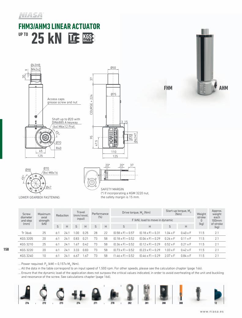
Tr 36x6 25 6:1 24:1 1.00 0.25 28 22 (0.58 x F) + 0.57 (0.18 x F) + 0.31 1.04 x F 0.40 x F 11.5 2.1
KGS 3205 20 6:1 24:1 0.83 0.21 73 58 (0.18 x F) + 0.52 (0.06 x F) + 0.29 0.26 x F 0.11 x F 11.5 2.1
KGS 3210 25 6:1 24:1 1.67 0.42 73 58 (0.36 x F) + 0.52 (0.12 x F) + 0.29 0.52 x F 0.21 x F 11.5 2.1
KGS 3220 20 6:1 24:1 3.33 0.83 73 58 (0.73 x F) + 0.52 (0.23 x F) + 0.29 1.03 x F 0.42 x F 11.5 2.1
KGS 3240 10 6:1 24:1 6.67 1.67 73 58 (1.46 x F) + 0.52 (0.46 x F) + 0.29 2.07 x F 0.84 x F 11.5 2.1
… Power required: PD (kW) = 0,157x M
D (Nm).
… All the data in the table correspond to an input speed of 1,500 rpm. For other speeds, please see the calculation chapter (page 166).... Ensure that the dynamic load of the application does not surpass the critical values indicated, in order to avoid overheating of the unit and buckling
and resonance of the screw. See calculations chapter (page 166).
276 272 273 274 271 278 282 281 280 308 307 312
FHM AHM
Shaft up to Ø11 withDIN6885 A keyway
Shaft up to Ø30 withDIN6885 A keyway
Shaft up to Ø24 withDIN6885 A keyway
70
HM1 HM2 HM3 HM4 HM5 HJ1 HJ3
LOWER GEARBOX FASTENING
220
(4x) M12x18 Prof.
Shaft up to Ø42 withDIN6885 A keyway
Shaft up to Ø34 withDIN6885 A keyway
Ø114 H8M110x2
6510
R80
Ø125
100
195
COU
RS
E +
360
Ø130
Ø150
Ø165(8x) M16x25
Ø100
45°
45°
97,5
Ø205
80300
Ø80
Ø14
0 H
7
260
= =
3 40
Access capsgrease screw and nut
20 20 110
SAFETY MARGINLOWER GEARBOX FASTENING
190
(4x) M10x16 Prof.
Ø100 H8M95x2
4510
R70Ø105
9518
0CO
UR
SE
+ 32
5
Ø110
Ø150
Ø45
Ø160(8x) M12x20
Ø90
45°
45°
Ø85
H7
16
268
71
220
3 30
Ø180
= =
Access capsgrease screw and nut
20 20 95
SAFETY MARGINLOWER GEARBOX FASTENING
160
(4x) M12x16 Prof.
Ø82 H8
M80x2
3710
R75
Ø100
6517
0CO
UR
SE
+ 30
0
Ø90
Ø115
Ø120(8x) M12x18
Ø80
45°
45°
85
= =
Ø145
71
226185
Ø40
Ø80
H7
252
Access capsgrease screw and nut
20 20 65
SAFETY MARGINLOWER GEARBOX FASTENING
144
(4x) M10x16 Prof.
Ø62 H8M60x2
359
R 65
Ø90
6714
0CO
UR
SE
+ 26
2
Ø70
Ø90
Ø 95
(8x) M10x16
Ø 62
45°
45°
22
70
3
= =
166
Ø35
Ø72
H7
196
Ø 125
63
Access capsgrease screw and nut
20 20 67
SAFETY MARGINLOWER GEARBOX FASTENING
110
(4x) M6x12 Prof.
Ø43 H8M42x2
309
Ø70
3795
COU
RS
E +
224
Ø50
Ø75
Ø70(8x) M8x16
Ø47
45°
45°
15
47,5
3
Ø98
45
125
Ø30
Ø62
H7
125
R40
Access capsgrease screw and nut
20* 20* 37
SAFETY MARGIN(*) If incorporating a KGM 3220 nut, the safety margin is 15 mm.LOWER GEARBOX FASTENING
100
Ø29 H8M27x2
267
Ø65
3689
COU
RS
E +
161
Ø35
Ø55
Ø65(8x) M6x12
Ø52
45°
45°
(4x) M5x10 Prof.
44,5
99
Ø85
112
32
Ø30
Ø60
H7
3
Access capsgrease screw and nut
20 20 36
SAFETY MARGINLOWER GEARBOX FASTENING
71
Ø27 H8
M26x1,5
206
Ø50
3662
,5CO
UR
SE
+ 12
0
Ø32
Ø40
Ø18
Ø50(8x) M5x10
Ø28
45°
45°
Ø35
H7
(4x) M5x8 Prof.
31,2
5
Ø60
25
3
7084
Access capsgrease screw and nut
20 20 36
SAFETY MARGIN
52
Shaft up to Ø20 withDIN6885 A keyway
Shaft up to Ø20 withDIN6885 A keyway
BALLS
www.niasa.es
04
159
Screw diameter and pitch
(mm)
Maximum axial
strength (kN)
Reduction Travel (mm/revol. input)
S H D S H D
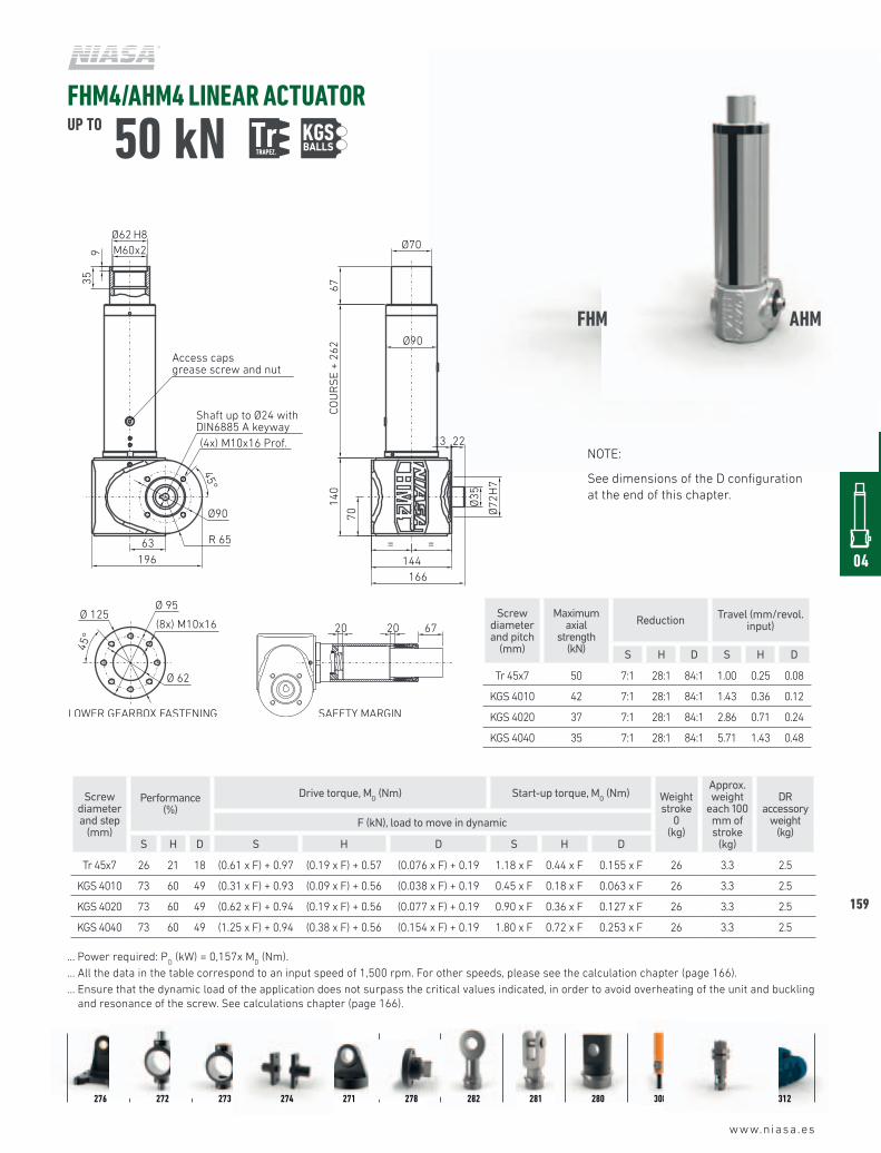
Tr 45x7 50 7:1 28:1 84:1 1.00 0.25 0.08
KGS 4010 42 7:1 28:1 84:1 1.43 0.36 0.12
KGS 4020 37 7:1 28:1 84:1 2.86 0.71 0.24
KGS 4040 35 7:1 28:1 84:1 5.71 1.43 0.48
Screw diameter and step
(mm)
Performance (%)
Drive torque, MD (Nm) Start-up torque, M
O (Nm) Weight
stroke 0
(kg)
Approx. weight
each 100 mm of stroke
(kg)
DR accessory
weight(kg)
F (kN), load to move in dynamic
S H D S H D S H D
Tr 45x7 26 21 18 (0.61 x F) + 0.97 (0.19 x F) + 0.57 (0.076 x F) + 0.19 1.18 x F 0.44 x F 0.155 x F 26 3.3 2.5
KGS 4010 73 60 49 (0.31 x F) + 0.93 (0.09 x F) + 0.56 (0.038 x F) + 0.19 0.45 x F 0.18 x F 0.063 x F 26 3.3 2.5
KGS 4020 73 60 49 (0.62 x F) + 0.94 (0.19 x F) + 0.56 (0.077 x F) + 0.19 0.90 x F 0.36 x F 0.127 x F 26 3.3 2.5
KGS 4040 73 60 49 (1.25 x F) + 0.94 (0.38 x F) + 0.56 (0.154 x F) + 0.19 1.80 x F 0.72 x F 0.253 x F 26 3.3 2.5
… Power required: PD (kW) = 0,157x M
D (Nm).
… All the data in the table correspond to an input speed of 1,500 rpm. For other speeds, please see the calculation chapter (page 166).... Ensure that the dynamic load of the application does not surpass the critical values indicated, in order to avoid overheating of the unit and buckling
and resonance of the screw. See calculations chapter (page 166).
FHM4/AHM4 LINEAR ACTUATORUP TO 50 kN Tr
TRAPEZ. KGS
NOTE:
See dimensions of the D configuration at the end of this chapter.
276 272 273 274 271 278 282 281 280 308 307 312
FHM AHM
Shaft up to Ø11 withDIN6885 A keyway
Shaft up to Ø30 withDIN6885 A keyway
Shaft up to Ø24 withDIN6885 A keyway
70
HM1 HM2 HM3 HM4 HM5 HJ1 HJ3
LOWER GEARBOX FASTENING
220
(4x) M12x18 Prof.
Shaft up to Ø42 withDIN6885 A keyway
Shaft up to Ø34 withDIN6885 A keyway
Ø114 H8M110x2
6510
R80
Ø125
100
195
COU
RS
E +
360
Ø130
Ø150
Ø165(8x) M16x25
Ø100
45°
45°
97,5
Ø205
80300
Ø80
Ø14
0 H
7
260
= =
3 40
Access capsgrease screw and nut
20 20 110
SAFETY MARGINLOWER GEARBOX FASTENING
190
(4x) M10x16 Prof.
Ø100 H8M95x2
4510
R70Ø105
9518
0CO
UR
SE
+ 32
5
Ø110
Ø150
Ø45
Ø160(8x) M12x20
Ø90
45°
45°
Ø85
H7
16
268
71
220
3 30
Ø180
= =
Access capsgrease screw and nut
20 20 95
SAFETY MARGINLOWER GEARBOX FASTENING
160
(4x) M12x16 Prof.
Ø82 H8
M80x2
3710
R75
Ø100
6517
0CO
UR
SE
+ 30
0
Ø90
Ø115
Ø120(8x) M12x18
Ø80
45°
45°
85
= =
Ø145
71
226185
Ø40
Ø80
H7
252
Access capsgrease screw and nut
20 20 65
SAFETY MARGINLOWER GEARBOX FASTENING
144
(4x) M10x16 Prof.
Ø62 H8M60x2
359
R 65
Ø90
6714
0CO
UR
SE
+ 26
2
Ø70
Ø90
Ø 95
(8x) M10x16
Ø 62
45°
45°
22
70
3
= =
166
Ø35
Ø72
H7
196
Ø 125
63
Access capsgrease screw and nut
20 20 67
SAFETY MARGINLOWER GEARBOX FASTENING
110
(4x) M6x12 Prof.
Ø43 H8M42x2
309
Ø70
3795
COU
RS
E +
224
Ø50
Ø75
Ø70(8x) M8x16
Ø47
45°
45°
15
47,5
3
Ø98
45
125
Ø30
Ø62
H7
125
R40
Access capsgrease screw and nut
20* 20* 37
SAFETY MARGIN(*) If incorporating a KGM 3220 nut, the safety margin is 15 mm.LOWER GEARBOX FASTENING
100
Ø29 H8M27x2
267
Ø65
3689
COU
RS
E +
161
Ø35
Ø55
Ø65(8x) M6x12
Ø52
45°
45°
(4x) M5x10 Prof.
44,5
99
Ø85
112
32
Ø30
Ø60
H7
3
Access capsgrease screw and nut
20 20 36
SAFETY MARGINLOWER GEARBOX FASTENING
71
Ø27 H8
M26x1,5
206
Ø50
3662
,5CO
UR
SE
+ 12
0
Ø32
Ø40
Ø18
Ø50(8x) M5x10
Ø28
45°
45°
Ø35
H7
(4x) M5x8 Prof.
31,2
5
Ø60
25
3
7084
Access capsgrease screw and nut
20 20 36
SAFETY MARGIN
52
Shaft up to Ø20 withDIN6885 A keyway
Shaft up to Ø20 withDIN6885 A keyway
BALLS
160
www.niasa.es
FHM5 ACTUATORUP TO 100 kN Tr
TRAPEZ. KGS
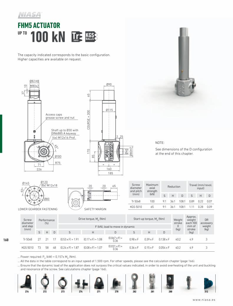
NOTE:
See dimensions of the D configuration at the end of this chapter.
Screw diameter and pitch
(mm)
Maximum axial
strength (kN)
Reduction Travel (mm/revol. input)
S H D S H D
Tr 50x8 100 9:1 36:1 108:1 0.89 0.22 0.07
KGS 5010 65 9:1 36:1 108:1 1.11 0.28 0.09
Screw diameter and step
(mm)
Performance (%)
Drive torque, MD (Nm) Start-up torque, M
O (Nm) Weight
stroke 0
(kg)
Approx. weight
each 100 mm of stroke
(kg)
DR accessory
weight(kg)
F (kN), load to move in dynamic
S H D S H D S H D
Tr 50x8 27 21 17 (0.53 x F) + 1.91 (0.17 x F) + 1.08 (0.067 x F) + 0.36 0.98 x F 0.39 x F 0.138 x F 40.2 4.9 3
KGS 5010 73 58 48 (0.24 x F) + 1.87 (0.08 x F) + 1.07 (0.031 x F) + 0.36 0.36 x F 0.15 x F 0.054 x F 40.2 4.9 3
… Power required: PD (kW) = 0,157x M
D (Nm).
… All the data in the table correspond to an input speed of 1,500 rpm. For other speeds, please see the calculation chapter (page 166).... Ensure that the dynamic load of the application does not surpass the critical values indicated, in order to avoid overheating of the unit and buckling
and resonance of the screw. See calculations chapter (page 166).
276 272 273 274 271 278 282 281 280 307 312
The capacity indicated corresponds to the basic configuration. Higher capacities are available on request.
Shaft up to Ø11 withDIN6885 A keyway
Shaft up to Ø30 withDIN6885 A keyway
Shaft up to Ø24 withDIN6885 A keyway
70
HM1 HM2 HM3 HM4 HM5 HJ1 HJ3
LOWER GEARBOX FASTENING
220
(4x) M12x18 Prof.
Shaft up to Ø42 withDIN6885 A keyway
Shaft up to Ø34 withDIN6885 A keyway
Ø114 H8M110x2
6510
R80
Ø125
100
195
COU
RS
E +
360
Ø130
Ø150
Ø165(8x) M16x25
Ø100
45°
45°
97,5
Ø205
80300
Ø80
Ø14
0 H
7
260
= =
3 40
Access capsgrease screw and nut
20 20 110
SAFETY MARGINLOWER GEARBOX FASTENING
190
(4x) M10x16 Prof.
Ø100 H8M95x2
4510
R70Ø105
9518
0CO
UR
SE
+ 32
5
Ø110
Ø150
Ø45
Ø160(8x) M12x20
Ø90
45°
45°
Ø85
H7
16
268
71
220
3 30
Ø180
= =
Access capsgrease screw and nut
20 20 95
SAFETY MARGINLOWER GEARBOX FASTENING
160
(4x) M12x16 Prof.
Ø82 H8
M80x2
3710
R75
Ø100
6517
0CO
UR
SE
+ 30
0Ø90
Ø115
Ø120(8x) M12x18
Ø80
45°
45°
85
= =
Ø145
71
226185
Ø40
Ø80
H7
252
Access capsgrease screw and nut
20 20 65
SAFETY MARGINLOWER GEARBOX FASTENING
144
(4x) M10x16 Prof.
Ø62 H8M60x2
359
R 65
Ø90
6714
0CO
UR
SE
+ 26
2
Ø70
Ø90
Ø 95
(8x) M10x16
Ø 62
45°
45°
22
70
3
= =
166
Ø35
Ø72
H7
196
Ø 125
63
Access capsgrease screw and nut
20 20 67
SAFETY MARGINLOWER GEARBOX FASTENING
110
(4x) M6x12 Prof.
Ø43 H8M42x2
309
Ø70
3795
COU
RS
E +
224
Ø50
Ø75
Ø70(8x) M8x16
Ø47
45°
45°
15
47,5
3
Ø98
45
125
Ø30
Ø62
H7
125
R40
Access capsgrease screw and nut
20* 20* 37
SAFETY MARGIN(*) If incorporating a KGM 3220 nut, the safety margin is 15 mm.LOWER GEARBOX FASTENING
100
Ø29 H8M27x2
267
Ø65
3689
COU
RS
E +
161
Ø35
Ø55
Ø65(8x) M6x12
Ø52
45°
45°
(4x) M5x10 Prof.
44,5
99
Ø85
112
32
Ø30
Ø60
H7
3
Access capsgrease screw and nut
20 20 36
SAFETY MARGINLOWER GEARBOX FASTENING
71
Ø27 H8
M26x1,5
206
Ø50
3662
,5CO
UR
SE
+ 12
0
Ø32
Ø40
Ø18
Ø50(8x) M5x10
Ø28
45°
45°
Ø35
H7
(4x) M5x8 Prof.
31,2
5
Ø60
25
3
7084
Access capsgrease screw and nut
20 20 36
SAFETY MARGIN
52
Shaft up to Ø20 withDIN6885 A keyway
Shaft up to Ø20 withDIN6885 A keyway
BALLS
www.niasa.es
04
161
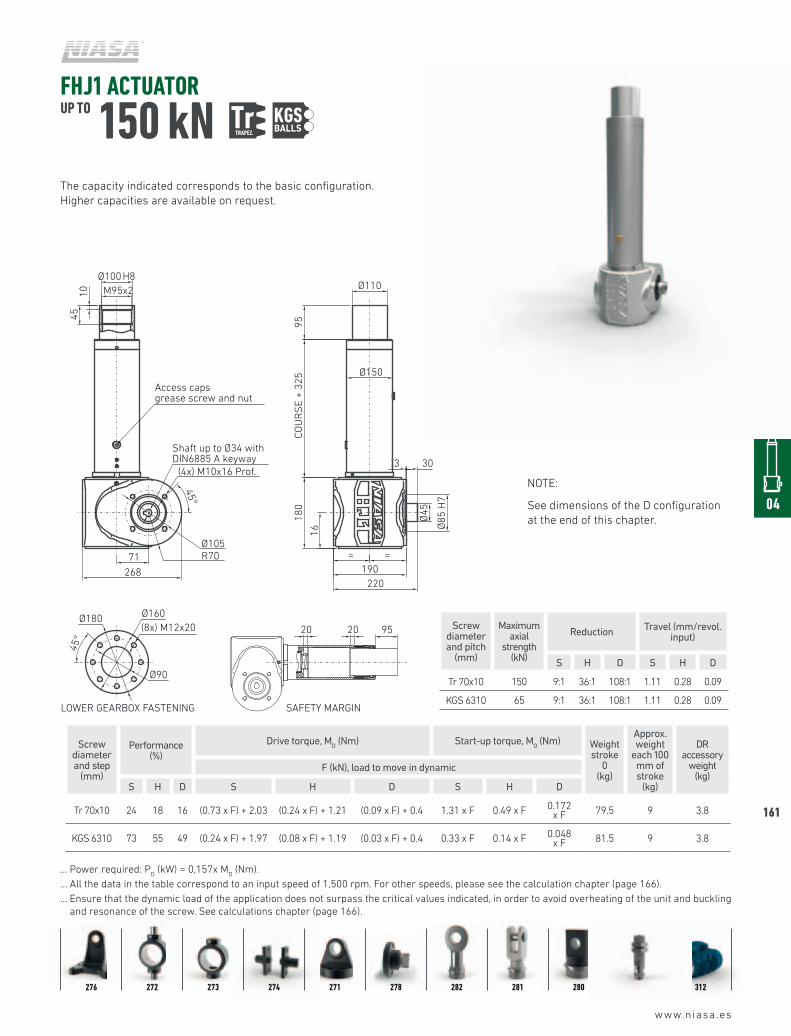
FHJ1 ACTUATOR UP TO 150 kN Tr
TRAPEZ. KGS
Screw diameter and pitch
(mm)
Maximum axial
strength (kN)
Reduction Travel (mm/revol. input)
S H D S H D
Tr 70x10 150 9:1 36:1 108:1 1.11 0.28 0.09
KGS 6310 65 9:1 36:1 108:1 1.11 0.28 0.09
Screw diameter and step
(mm)
Performance (%)
Drive torque, MD (Nm) Start-up torque, M
O (Nm) Weight
stroke 0
(kg)
Approx. weight
each 100 mm of stroke
(kg)
DR accessory
weight(kg)
F (kN), load to move in dynamic
S H D S H D S H D
Tr 70x10 24 18 16 (0.73 x F) + 2.03 (0.24 x F) + 1.21 (0.09 x F) + 0.4 1.31 x F 0.49 x F 0.172 x F 79.5 9 3.8
KGS 6310 73 55 49 (0.24 x F) + 1.97 (0.08 x F) + 1.19 (0.03 x F) + 0.4 0.33 x F 0.14 x F 0.048 x F 81.5 9 3.8
… Power required: PD (kW) = 0,157x M
D (Nm).
… All the data in the table correspond to an input speed of 1,500 rpm. For other speeds, please see the calculation chapter (page 166).... Ensure that the dynamic load of the application does not surpass the critical values indicated, in order to avoid overheating of the unit and buckling
and resonance of the screw. See calculations chapter (page 166).
NOTE:
See dimensions of the D configuration at the end of this chapter.
276 272 273 274 271 278 282 281 280 307 312
The capacity indicated corresponds to the basic configuration. Higher capacities are available on request.
Shaft up to Ø11 withDIN6885 A keyway
Shaft up to Ø30 withDIN6885 A keyway
Shaft up to Ø24 withDIN6885 A keyway
70
HM1 HM2 HM3 HM4 HM5 HJ1 HJ3
LOWER GEARBOX FASTENING
220
(4x) M12x18 Prof.
Shaft up to Ø42 withDIN6885 A keyway
Shaft up to Ø34 withDIN6885 A keyway
Ø114 H8M110x2
6510
R80
Ø125
100
195
COU
RS
E +
360
Ø130
Ø150
Ø165(8x) M16x25
Ø100
45°
45°
97,5
Ø205
80300
Ø80
Ø14
0 H
7
260
= =
3 40
Access capsgrease screw and nut
20 20 110
SAFETY MARGINLOWER GEARBOX FASTENING
190
(4x) M10x16 Prof.
Ø100 H8M95x2
4510
R70Ø105
9518
0CO
UR
SE
+ 32
5Ø110
Ø150
Ø45
Ø160(8x) M12x20
Ø90
45°
45°
Ø85
H7
16
268
71
220
3 30
Ø180
= =
Access capsgrease screw and nut
20 20 95
SAFETY MARGINLOWER GEARBOX FASTENING
160
(4x) M12x16 Prof.
Ø82 H8
M80x2
3710
R75
Ø100
6517
0CO
UR
SE
+ 30
0
Ø90
Ø115
Ø120(8x) M12x18
Ø80
45°
45°
85
= =
Ø145
71
226185
Ø40
Ø80
H7
252
Access capsgrease screw and nut
20 20 65
SAFETY MARGINLOWER GEARBOX FASTENING
144
(4x) M10x16 Prof.
Ø62 H8M60x2
359
R 65
Ø90
6714
0CO
UR
SE
+ 26
2
Ø70
Ø90
Ø 95
(8x) M10x16
Ø 62
45°
45°
22
70
3
= =
166
Ø35
Ø72
H7
196
Ø 125
63
Access capsgrease screw and nut
20 20 67
SAFETY MARGINLOWER GEARBOX FASTENING
110
(4x) M6x12 Prof.
Ø43 H8M42x2
309
Ø70
3795
COU
RS
E +
224
Ø50
Ø75
Ø70(8x) M8x16
Ø47
45°
45°
15
47,5
3
Ø98
45
125
Ø30
Ø62
H7
125
R40
Access capsgrease screw and nut
20* 20* 37
SAFETY MARGIN(*) If incorporating a KGM 3220 nut, the safety margin is 15 mm.LOWER GEARBOX FASTENING
100
Ø29 H8M27x2
267
Ø65
3689
COU
RS
E +
161
Ø35
Ø55
Ø65(8x) M6x12
Ø52
45°
45°
(4x) M5x10 Prof.
44,5
99
Ø85
112
32
Ø30
Ø60
H7
3
Access capsgrease screw and nut
20 20 36
SAFETY MARGINLOWER GEARBOX FASTENING
71
Ø27 H8
M26x1,5
206
Ø50
3662
,5CO
UR
SE
+ 12
0
Ø32
Ø40
Ø18
Ø50(8x) M5x10
Ø28
45°
45°
Ø35
H7
(4x) M5x8 Prof.
31,2
5
Ø60
25
3
7084
Access capsgrease screw and nut
20 20 36
SAFETY MARGIN
52
Shaft up to Ø20 withDIN6885 A keyway
Shaft up to Ø20 withDIN6885 A keyway
BALLS
162
www.niasa.es
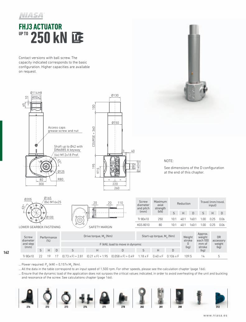
FHJ3 ACTUATOR UP TO 250 kN Tr
TRAPEZ.
NOTE:
See dimensions of the D configuration at the end of this chapter.
Screw diameter and pitch
(mm)
Maximum axial
strength (kN)
Reduction Travel (mm/revol. input)
S H D S H D
Tr 80x10 250 10:1 40:1 160:1 1.00 0.25 0.06
KGS 8010 80 10:1 40:1 160:1 1.00 0.25 0.06
Screw diameter and step
(mm)
Performance (%)
Drive torque, MD (Nm) Start-up torque, M
O (Nm) Weight
stroke 0
(kg)
Approx. weight
each 100 mm of stroke
(kg)
DR accessory
weight(kg)
F (kN), load to move in dynamic
S H D S H D S H D
Tr 80x10 22 19 17 (0.73 x F) + 2.81 (0.21 x F) + 1.95 (0.058 x F) + 0.49 1.18 x F 0.40 x F 0.106 x F 109.5 14 5
… Power required: PD (kW) = 0,157x M
D (Nm).
… All the data in the table correspond to an input speed of 1,500 rpm. For other speeds, please see the calculation chapter (page 166).... Ensure that the dynamic load of the application does not surpass the critical values indicated, in order to avoid overheating of the unit and buckling
and resonance of the screw. See calculations chapter (page 166).
Contact versions with ball screw. The capacity indicated corresponds to the basic configuration. Higher capacities are available on request.
276 272 273 274 271 278 282 281 280 307 312
Shaft up to Ø11 withDIN6885 A keyway
Shaft up to Ø30 withDIN6885 A keyway
Shaft up to Ø24 withDIN6885 A keyway
70
HM1 HM2 HM3 HM4 HM5 HJ1 HJ3
LOWER GEARBOX FASTENING
220
(4x) M12x18 Prof.
Shaft up to Ø42 withDIN6885 A keyway
Shaft up to Ø34 withDIN6885 A keyway
Ø114 H8M110x2
6510
R80
Ø125
100
195
COU
RS
E +
360
Ø130
Ø150
Ø165(8x) M16x25
Ø100
45°
45°
97,5
Ø205
80300
Ø80
Ø14
0 H
7
260
= =
3 40
Access capsgrease screw and nut
20 20 110
SAFETY MARGINLOWER GEARBOX FASTENING
190
(4x) M10x16 Prof.
Ø100 H8M95x2
4510
R70Ø105
9518
0CO
UR
SE
+ 32
5
Ø110
Ø150
Ø45
Ø160(8x) M12x20
Ø90
45°
45°
Ø85
H7
16
268
71
220
3 30
Ø180
= =
Access capsgrease screw and nut
20 20 95
SAFETY MARGINLOWER GEARBOX FASTENING
160
(4x) M12x16 Prof.
Ø82 H8
M80x2
3710
R75
Ø100
6517
0CO
UR
SE
+ 30
0
Ø90
Ø115
Ø120(8x) M12x18
Ø80
45°
45°
85
= =
Ø145
71
226185
Ø40
Ø80
H7
252
Access capsgrease screw and nut
20 20 65
SAFETY MARGINLOWER GEARBOX FASTENING
144
(4x) M10x16 Prof.
Ø62 H8M60x2
359
R 65
Ø90
6714
0CO
UR
SE
+ 26
2
Ø70
Ø90
Ø 95
(8x) M10x16
Ø 62
45°
45°
22
70
3
= =
166
Ø35
Ø72
H7
196
Ø 125
63
Access capsgrease screw and nut
20 20 67
SAFETY MARGINLOWER GEARBOX FASTENING
110
(4x) M6x12 Prof.
Ø43 H8M42x2
309
Ø70
3795
COU
RS
E +
224
Ø50
Ø75
Ø70(8x) M8x16
Ø47
45°
45°
15
47,5
3
Ø98
45
125
Ø30
Ø62
H7
125
R40
Access capsgrease screw and nut
20* 20* 37
SAFETY MARGIN(*) If incorporating a KGM 3220 nut, the safety margin is 15 mm.LOWER GEARBOX FASTENING
100
Ø29 H8M27x2
267
Ø65
3689
COU
RS
E +
161
Ø35
Ø55
Ø65(8x) M6x12
Ø52
45°
45°
(4x) M5x10 Prof.
44,5
99
Ø85
112
32
Ø30
Ø60
H7
3
Access capsgrease screw and nut
20 20 36
SAFETY MARGINLOWER GEARBOX FASTENING
71
Ø27 H8
M26x1,5
206
Ø50
3662
,5CO
UR
SE
+ 12
0
Ø32
Ø40
Ø18
Ø50(8x) M5x10
Ø28
45°
45°
Ø35
H7
(4x) M5x8 Prof.
31,2
5
Ø60
25
3
7084
Access capsgrease screw and nut
20 20 36
SAFETY MARGIN
52
Shaft up to Ø20 withDIN6885 A keyway
Shaft up to Ø20 withDIN6885 A keyway
www.niasa.es
04
163
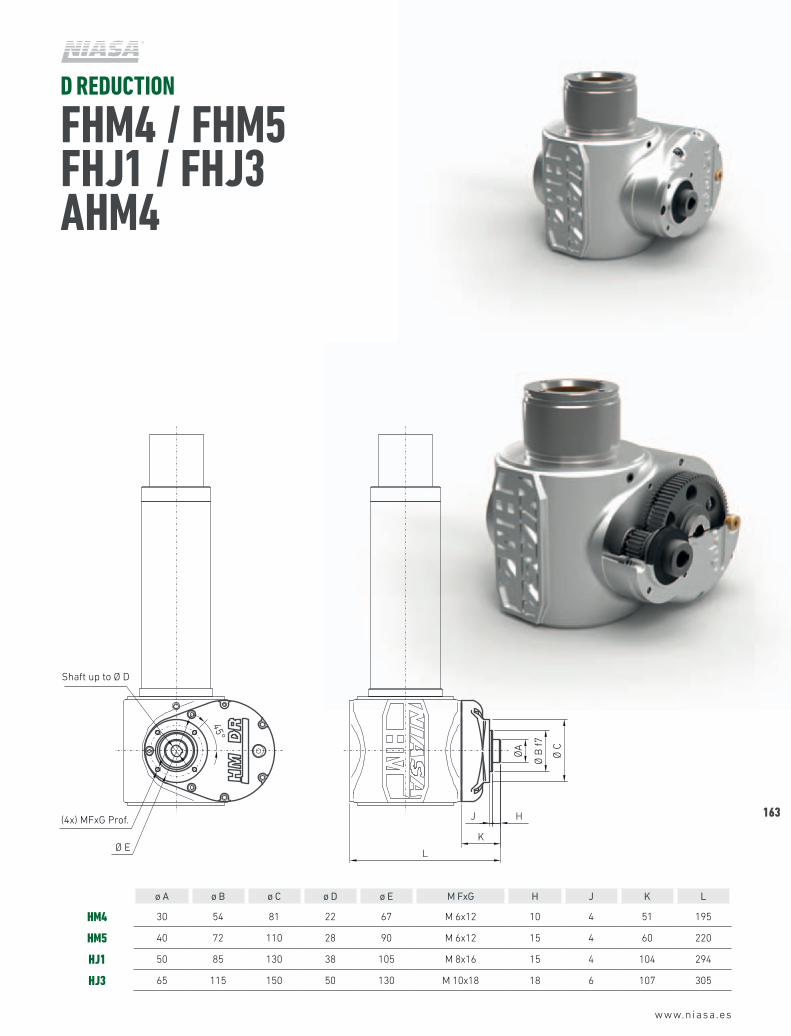
ø A ø B ø C ø D ø E M FxG H J K L
HM4 30 54 81 22 67 M 6x12 10 4 51 195
HM5 40 72 110 28 90 M 6x12 15 4 60 220
HJ1 50 85 130 38 105 M 8x16 15 4 104 294
HJ3 65 115 150 50 130 M 10x18 18 6 107 305
D REDUCTION
FHM4 / FHM5 FHJ1 / FHJ3 AHM4
Ø E
(4x) MFxG Prof.
45°
K
H
ØA
Ø B
f7
J
L
Ø C
Shaft up to Ø D
DR (HM4 - HM5 - HJ1 - HJ3)
Insertar tabla dimensiones
164
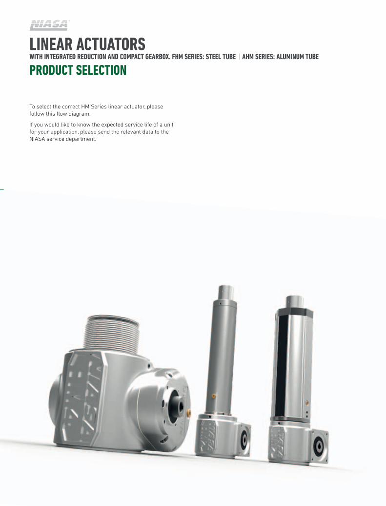
LINEAR ACTUATORS WITH INTEGRATED REDUCTION AND COMPACT GEARBOX. FHM SERIES: STEEL TUBE | AHM SERIES: ALUMINUM TUBE
PRODUCT SELECTION
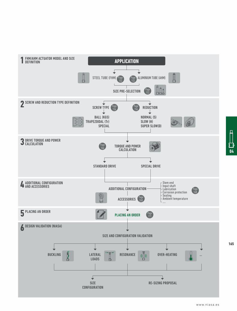
To select the correct HM Series linear actuator, please follow this flow diagram.
If you would like to know the expected service life of a unit for your application, please send the relevant data to the NIASA service department.
www.niasa.es
04
165
APPLICATION
6
5
4
3
2
1
STEEL TUBE (FHM)
Ball (KGS) Trapezoidal (Tr)
SpeCial
SCreW TYpe
ALUMINIUM TUBE (AHM)
- Stem end- Input shaft- Lubrication - Corrosion protection- Sealing- Ambient temperature- ....
NorMal (S)SloW (H)Super SloW(d)
reduCTioN
Size pre-SeleCTioN
Page 152
Page 152
Page 152
Page 166
Page 260
Page 168
Page 171
Page 156
Page 156
STaNdard driVe
addiTioNal CoNFiGuraTioN
aCCeSSorieS
plaCiNG aN order
TorQue aNd poWer CalCulaTioN
SpeCial driVe
SCreW aNd reduCTioN TYpe deFiNiTioN
FHM/aHM aCTuaTor Model aNd Size deFiNiTioN
driVe TorQue aNd poWer CalCulaTioN
addiTioNal CoNFiGuraTioN aNd aCCeSSorieS
plaCiNG aN order
deSiGN ValidaTioN (NiaSa)
Size aNd CoNFiGuraTioN ValidaTioN
Size CoNFiGuraTioN
re-SiziNG propoSal
BuCKliNG laTeral loadS
reSoNaNCe oVer-HeaTiNG …F F F
166166
TORQUE AND POWER OF A LINEAR ACTUATORHM SERIES LINEAR
LINEAR ACTUATORS WITH INTEGRATED REDUCTION AND COMPACT GEARBOX. FHM SERIES: STEEL TUBE | AHM SERIES: ALUMINUM TUBE
PRODUCT SELECTION
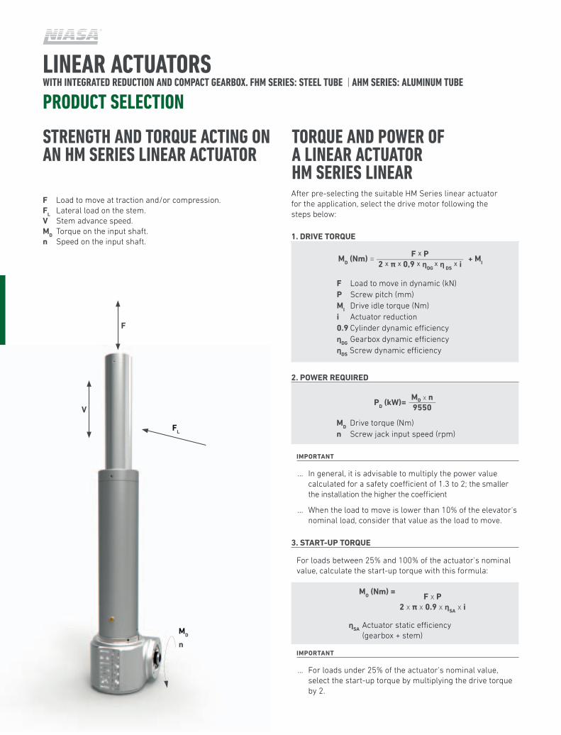
After pre-selecting the suitable HM Series linear actuator for the application, select the drive motor following the steps below:
1. DRIVE TORQUE
2. POWER REQUIRED
ImPORTAnT
… In general, it is advisable to multiply the power value calculated for a safety coefficient of 1.3 to 2; the smaller the installation the higher the coefficient
… When the load to move is lower than 10% of the elevator's nominal load, consider that value as the load to move.
3. START-UP TORQUE
For loads between 25% and 100% of the actuator's nominal value, calculate the start-up torque with this formula:
mO (nm) =
ImPORTAnT
… For loads under 25% of the actuator's nominal value, select the start-up torque by multiplying the drive torque by 2.
ηSA Actuator static efficiency (gearbox + stem)
F x P2 x π x 0.9 x ηSA x i
STRENGTH AND TORQUE ACTING ON AN HM SERIES LINEAR ACTUATOR
F Load to move at traction and/or compression.FL Lateral load on the stem.V Stem advance speed.mD Torque on the input shaft.n Speed on the input shaft.
F
FL
mD
n
V
mD Drive torque (Nm)n Screw jack input speed (rpm)
F Load to move in dynamic (kN) P Screw pitch (mm)mI Drive idle torque (Nm)i Actuator reduction0.9 Cylinder dynamic efficiencyηDG Gearbox dynamic efficiencyηDS Screw dynamic efficiency
mD (nm) = + mI
F x P2 x π x 0,9 x ηDG
x η DS x i
mD x n9550
PD (kW)=
www.niasa.es
04
167
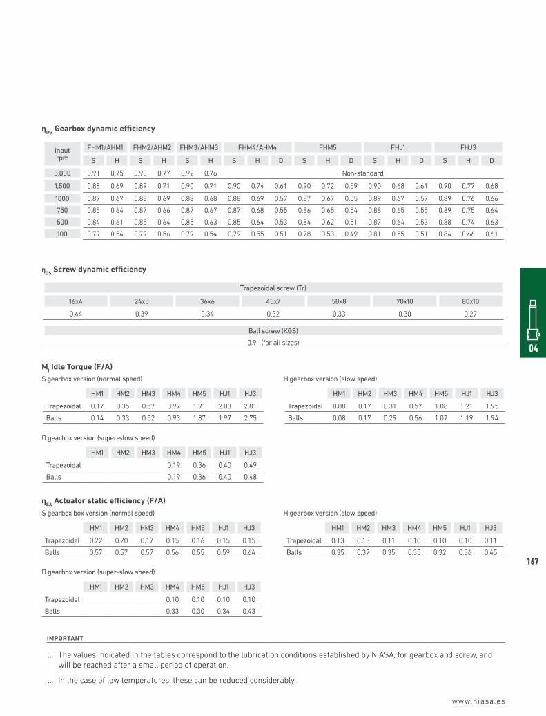
ImPORTAnT
… The values indicated in the tables correspond to the lubrication conditions established by NIASA, for gearbox and screw, and will be reached after a small period of operation.
… In the case of low temperatures, these can be reduced considerably.
HM1 HM2 HM3 HM4 HM5 HJ1 HJ3
Trapezoidal 0.13 0.13 0.11 0.10 0.10 0.10 0.11
Balls 0.35 0.37 0.35 0.35 0.32 0.36 0.45
ηSA Actuator static efficiency (F/A)
HM1 HM2 HM3 HM4 HM5 HJ1 HJ3
Trapezoidal 0.22 0.20 0.17 0.15 0.16 0.15 0.15
Balls 0.57 0.57 0.57 0.56 0.55 0.59 0.64
HM1 HM2 HM3 HM4 HM5 HJ1 HJ3
Trapezoidal 0.10 0.10 0.10 0.10
Balls 0.33 0.30 0.34 0.43
S gearbox box version (normal speed)
D gearbox version (super-slow speed)
H gearbox version (slow speed)
mI Idle Torque (F/A)
HM1 HM2 HM3 HM4 HM5 HJ1 HJ3
Trapezoidal 0.17 0.35 0.57 0.97 1.91 2.03 2.81
Balls 0.14 0.33 0.52 0.93 1.87 1.97 2.75
S gearbox version (normal speed)
HM1 HM2 HM3 HM4 HM5 HJ1 HJ3
Trapezoidal 0.08 0.17 0.31 0.57 1.08 1.21 1.95
Balls 0.08 0.17 0.29 0.56 1.07 1.19 1.94
H gearbox version (slow speed)
HM1 HM2 HM3 HM4 HM5 HJ1 HJ3
Trapezoidal 0.19 0.36 0.40 0.49
Balls 0.19 0.36 0.40 0.48
D gearbox version (super-slow speed)
input rpm
FHM1/AHM1 FHM2/AHM2 FHM3/AHM3 FHM4/AHM4 FHM5 FHJ1 FHJ3
S H S H S H S H D S H D S H D S H D
3,000 0.91 0.75 0.90 0.77 0.92 0.76 Non-standard
1,500 0.88 0.69 0.89 0.71 0.90 0.71 0.90 0.74 0.61 0.90 0.72 0.59 0.90 0.68 0.61 0.90 0.77 0.68
1000 0.87 0.67 0.88 0.69 0.88 0.68 0.88 0.69 0.57 0.87 0.67 0.55 0.89 0.67 0.57 0.89 0.76 0.66
750 0.85 0.64 0.87 0.66 0.87 0.67 0.87 0.68 0.55 0.86 0.65 0.54 0.88 0.65 0.55 0.89 0.75 0.64
500 0.84 0.61 0.85 0.64 0.85 0.63 0.85 0.64 0.53 0.84 0.62 0.51 0.87 0.64 0.53 0.88 0.74 0.63
100 0.79 0.54 0.79 0.56 0.79 0.54 0.79 0.55 0.51 0.78 0.53 0.49 0.81 0.55 0.51 0.84 0.66 0.61
ηDG Gearbox dynamic efficiency
Trapezoidal screw (Tr)
16x4 24x5 36x6 45x7 50x8 70x10 80x10
0.44 0.39 0.34 0.32 0.33 0.30 0.27
Ball screw (KGS)
0.9 (for all sizes)
ηDS Screw dynamic efficiency
168
www.niasa.es
LINEAR ACTUATORS WITH INTEGRATED REDUCTION AND COMPACT GEARBOX. FHM SERIES: STEEL TUBE | AHM SERIES: ALUMINUM TUBE
PRODUCT SELECTION
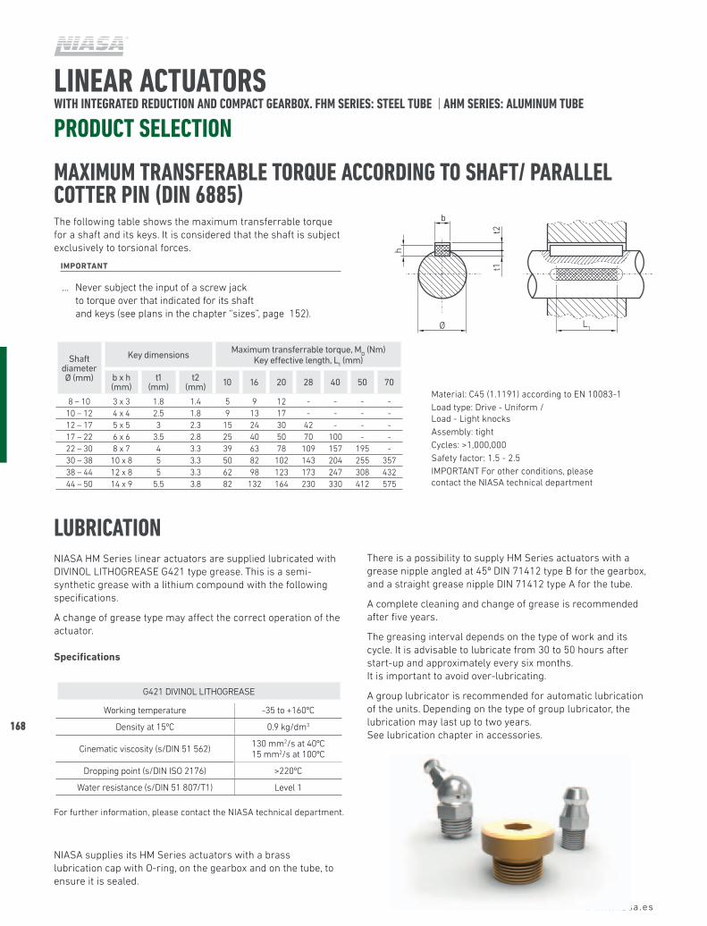
LUBRICATIONNIASA HM Series linear actuators are supplied lubricated with DIVINOL LITHOGREASE G421 type grease. This is a semi-synthetic grease with a lithium compound with the following specifications.
A change of grease type may affect the correct operation of the actuator.
Specifications
NIASA supplies its HM Series actuators with a brass lubrication cap with O-ring, on the gearbox and on the tube, to ensure it is sealed.
There is a possibility to supply HM Series actuators with a grease nipple angled at 45º DIN 71412 type B for the gearbox, and a straight grease nipple DIN 71412 type A for the tube.
A complete cleaning and change of grease is recommended after five years.
The greasing interval depends on the type of work and its cycle. It is advisable to lubricate from 30 to 50 hours after start-up and approximately every six months. It is important to avoid over-lubricating.
A group lubricator is recommended for automatic lubrication of the units. Depending on the type of group lubricator, the lubrication may last up to two years. See lubrication chapter in accessories.
G421 DIVINOL LITHOGREASE
Working temperature -35 to +160ºC
Density at 15ºC 0.9 kg/dm3
Cinematic viscosity (s/DIN 51 562) 130 mm2/s at 40ºC 15 mm2/s at 100ºC
Dropping point (s/DIN ISO 2176) >220ºC
Water resistance (s/DIN 51 807/T1) Level 1
For further information, please contact the NIASA technical department.
The following table shows the maximum transferrable torque for a shaft and its keys. It is considered that the shaft is subject exclusively to torsional forces.
ImPORTAnT
… Never subject the input of a screw jack to torque over that indicated for its shaft and keys (see plans in the chapter “sizes”, page 152).
MAXIMUM TRANSFERABLE TORQUE ACCORDING TO SHAFT/ PARALLEL COTTER PIN (DIN 6885)
Shaft diameter Ø (mm)
Key dimensions Maximum transferrable torque, MD (Nm)
Key effective length, L1 (mm)
b x h (mm)
t1 (mm)
t2 (mm) 10 16 20 28 40 50 70
8 – 10 3 x 3 1.8 1.4 5 9 12 - - - -10 – 12 4 x 4 2.5 1.8 9 13 17 - - - -12 – 17 5 x 5 3 2.3 15 24 30 42 - - -17 – 22 6 x 6 3.5 2.8 25 40 50 70 100 - -22 – 30 8 x 7 4 3.3 39 63 78 109 157 195 -30 – 38 10 x 8 5 3.3 50 82 102 143 204 255 357 38 – 44 12 x 8 5 3.3 62 98 123 173 247 308 432 44 – 50 14 x 9 5.5 3.8 82 132 164 230 330 412 575
Material: C45 (1.1191) according to EN 10083-1Load type: Drive - Uniform / Load - Light knocksAssembly: tightCycles: >1,000,000Safety factor: 1.5 - 2.5IMPORTANT For other conditions, please contact the NIASA technical department
b
t2
Ø
t1
h
L1
www.niasa.es
04
169
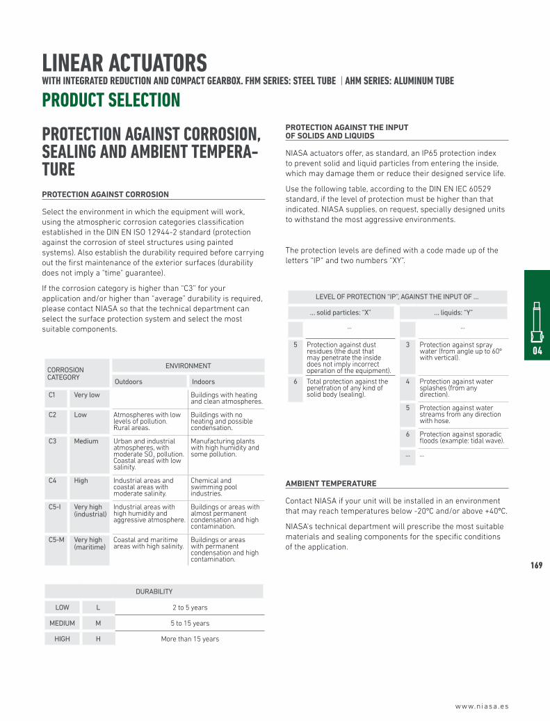
PROTECTION AGAINST CORROSION, SEALING AND AMBIENT TEMPERA-TUREPROTECTIOn AGAInST CORROSIOn
Select the environment in which the equipment will work, using the atmospheric corrosion categories classification established in the DIN EN ISO 12944-2 standard (protection against the corrosion of steel structures using painted systems). Also establish the durability required before carrying out the first maintenance of the exterior surfaces (durability does not imply a "time" guarantee).
If the corrosion category is higher than “C3” for your application and/or higher than “average” durability is required, please contact NIASA so that the technical department can select the surface protection system and select the most suitable components.
CORROSION CATEGORY
ENVIRONMENT
Outdoors Indoors
C1 Very low Buildings with heating and clean atmospheres.
C2 Low Atmospheres with low levels of pollution. Rural areas.
Buildings with no heating and possible condensation.
C3 Medium Urban and industrial atmospheres, with moderate SO
2 pollution.
Coastal areas with low salinity.
Manufacturing plants with high humidity and some pollution.
C4 High Industrial areas and coastal areas with moderate salinity.
Chemical and swimming pool industries.
C5-I Very high (industrial)
Industrial areas with high humidity and aggressive atmosphere.
Buildings or areas with almost permanent condensation and high contamination.
C5-M Very high(maritime)
Coastal and maritime areas with high salinity.
Buildings or areas with permanent condensation and high contamination.
DURABILITY
LOW L 2 to 5 years
MEDIUM M 5 to 15 years
HIGH H More than 15 years
PROTECTIOn AGAInST THE InPUT OF SOLIDS AnD LIQUIDS
NIASA actuators offer, as standard, an IP65 protection index to prevent solid and liquid particles from entering the inside, which may damage them or reduce their designed service life.
Use the following table, according to the DIN EN IEC 60529 standard, if the level of protection must be higher than that indicated. NIASA supplies, on request, specially designed units to withstand the most aggressive environments.
The protection levels are defined with a code made up of the letters “IP“ and two numbers “XY”.
LEVEL OF PROTECTION “IP”, AGAINST THE INPUT OF …
… solid particles: “X” … liquids: “Y”
... ...
5 Protection against dust residues (the dust that may penetrate the inside does not imply incorrect operation of the equipment).
3 Protection against spray water (from angle up to 60º with vertical).
6 Total protection against the penetration of any kind of solid body (sealing).
4 Protection against water splashes (from any direction).
5 Protection against water streams from any direction with hose.
6 Protection against sporadic floods (example: tidal wave).
... ...
AmBIEnT TEmPERATURE
Contact NIASA if your unit will be installed in an environment that may reach temperatures below -20ºC and/or above +40ºC.
NIASA's technical department will prescribe the most suitable materials and sealing components for the specific conditions of the application.
LINEAR ACTUATORS WITH INTEGRATED REDUCTION AND COMPACT GEARBOX. FHM SERIES: STEEL TUBE | AHM SERIES: ALUMINUM TUBE
PRODUCT SELECTION
170
www.niasa.es
LINEAR ACTUATORS WITH INTEGRATED REDUCTION AND COMPACT GEARBOX. FHM SERIES: STEEL TUBE | AHM SERIES: ALUMINUM TUBE
PRODUCT SELECTION
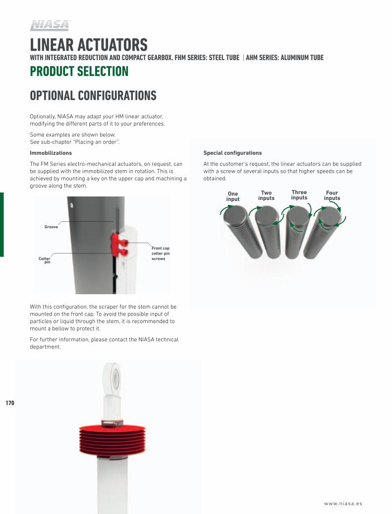
Special configurations
At the customer's request, the linear actuators can be supplied with a screw of several inputs so that higher speeds can be obtained.
Three inputs
One input
Two inputs
Four inputs
OPTIONAL CONFIGURATIONSOptionally, NIASA may adapt your HM linear actuator, modifying the different parts of it to your preferences.
Some examples are shown below. See sub-chapter “Placing an order”.
Immobilizations
The FM Series electro-mechanical actuators, on request, can be supplied with the immobilized stem in rotation. This is achieved by mounting a key on the upper cap and machining a groove along the stem.
With this configuration, the scraper for the stem cannot be mounted on the front cap. To avoid the possible input of particles or liquid through the stem, it is recommended to mount a bellow to protect it.
For further information, please contact the NIASA technical department.
Front cap cotter pin screwsCotter
pin
Groove
www.niasa.es
04
171
LINEAR ACTUATORS WITH INTEGRATED REDUCTION AND COMPACT GEARBOX. FHM SERIES: STEEL TUBE | AHM SERIES: ALUMINUM TUBE
PLACING AN ORDER
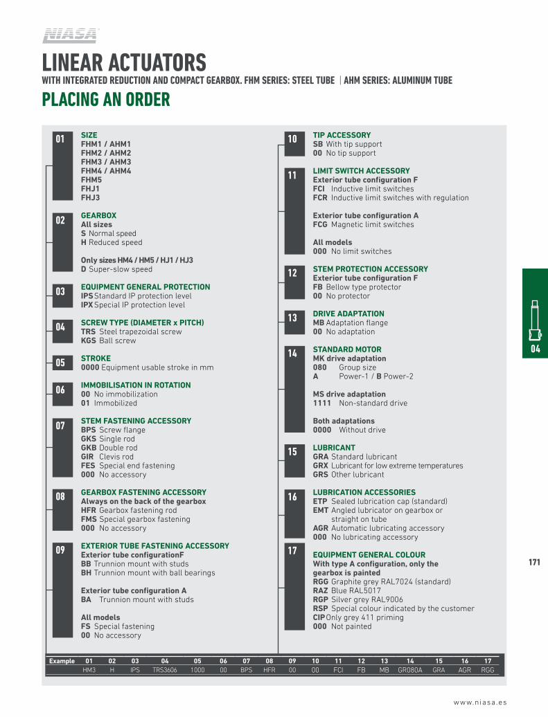
SIZEFHm1 / AHm1FHm2 / AHm2FHm3 / AHm3FHm4 / AHm4FHm5FHJ1FHJ3
GEARBOXAll sizesS Normal speedH Reduced speed
Only sizes Hm4 / Hm5 / HJ1 / HJ3D Super-slow speed
EQUIPmEnT GEnERAL PROTECTIOnIPS Standard IP protection levelIPX Special IP protection level
SCREW TYPE (DIAmETER x PITCH)TRS Steel trapezoidal screwKGS Ball screw
STROKE0000 Equipment usable stroke in mm
ImmOBILISATIOn In ROTATIOn00 No immobilization01 Immobilized
STEm FASTEnInG ACCESSORYBPS Screw flangeGKS Single rodGKB Double rodGIR Clevis rodFES Special end fastening000 No accessory
GEARBOX FASTEnInG ACCESSORYAlways on the back of the gearboxHFR Gearbox fastening rodFmS Special gearbox fastening000 No accessory
EXTERIOR TUBE FASTEnInG ACCESSORYExterior tube configurationFBB Trunnion mount with studsBH Trunnion mount with ball bearings
Exterior tube configuration ABA Trunnion mount with studs
All modelsFS Special fastening00 No accessory
10
11
12
16
15
14
13
17
01
02
03
05
07
08
09
04
06
TIP ACCESSORYSB With tip support00 No tip support
LImIT SWITCH ACCESSORYExterior tube configuration FFCI Inductive limit switchesFCR Inductive limit switches with regulation
Exterior tube configuration AFCG Magnetic limit switches
All models000 No limit switches
STEm PROTECTIOn ACCESSORYExterior tube configuration FFB Bellow type protector00 No protector
DRIVE ADAPTATIOnmB Adaptation flange00 No adaptation
STAnDARD mOTORmK drive adaptation080 Group sizeA Power-1 / B Power-2
mS drive adaptation1111 Non-standard drive
Both adaptations0000 Without drive
LUBRICAnTGRA Standard lubricantGRX Lubricant for low extreme temperaturesGRS Other lubricant
LUBRICATIOn ACCESSORIESETP Sealed lubrication cap (standard)EmT Angled lubricator on gearbox or
straight on tubeAGR Automatic lubricating accessory000 No lubricating accessory
EQUIPmEnT GEnERAL COLOUR With type A configuration, only the gearbox is paintedRGG Graphite grey RAL7024 (standard)RAZ Blue RAL5017RGP Silver grey RAL9006RSP Special colour indicated by the customerCIP Only grey 411 priming000 Not painted
Example 01 02 03 04 05 06 07 08 09 10 11 12 13 14 15 16 17HM3 H IPS TRS3606 1000 00 BPS HFR 00 00 FCI FB MB GR080A GRA AGR RGG
172
www.niasa.es
LINEAR ACTUATORS WITH INTEGRATED REDUCTION AND COMPACT GEARBOX. FHM SERIES: STEEL TUBE | AHM SERIES: ALUMINUM TUBE
DISASSEMBLY
621
138
28
16
37
17
3512
18
41
19
19
39
10
5
29
3
2332
4
20
7
20
25
2
11
9
15
14
8
40
13
24
30
31
2738
4122
36
www.niasa.es
04
173
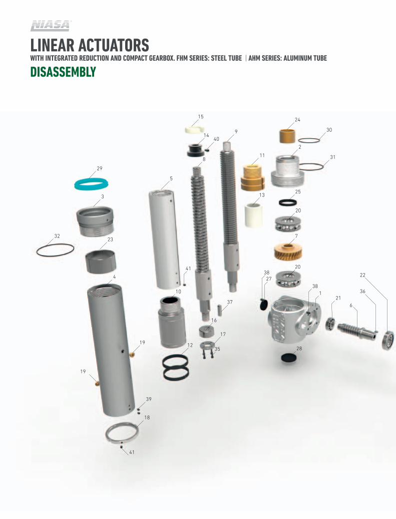
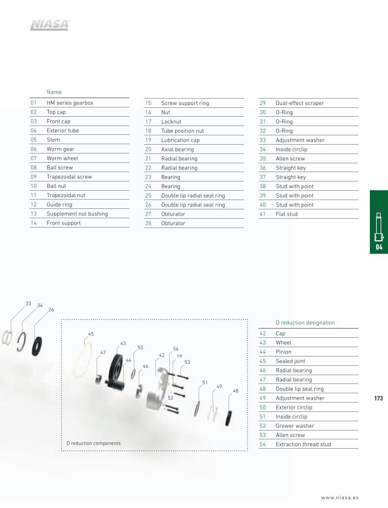
Name
01 HM series gearbox
02 Top cap
03 Front cap
04 Exterior tube
05 Stem
06 Worm gear
07 Worm wheel
08 Ball screw
09 Trapezoidal screw
10 Ball nut
11 Trapezoidal nut
12 Guide ring
13 Supplement nut bushing
14 Front support
D reduction designation
42 Cap
43 Wheel
44 Pinion
45 Sealed joint
46 Radial bearing
47 Radial bearing
48 Double lip seal ring
49 Adjustment washer
50 Exterior circlip
51 Inside circlip
52 Grower washer
53 Allen screw
54 Extraction thread stud
4849
51
52
4653
54
1942
5043
45
263433
44
47
D reduction components
15 Screw support ring
16 Nut
17 Locknut
18 Tube position nut
19 Lubrication cap
20 Axial bearing
21 Radial bearing
22 Radial bearing
23 Bearing
24 Bearing
25 Double lip radial seal ring
26 Double lip radial seal ring
27 Obturator
28 Obturator
29 Dual-effect scraper
30 O-Ring
31 O-Ring
32 O-Ring
33 Adjustment washer
34 Inside circlip
35 Allen screw
36 Straight key
37 Straight key
38 Stud with point
39 Stud with point
40 Stud with point
41 Flat stud
174
LINEAR ACTUATORS WITH INTEGRATED REDUCTION AND COMPACT GEARBOX. FHM SERIES: STEEL TUBE | AHM SERIES: ALUMINUM TUBE
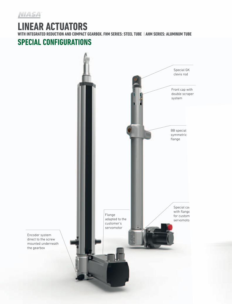
SPECIAL CONFIGURATIONS
Encoder system direct to the screw mounted underneath the gearbox
Flange adapted to the customer's servomotor
Special GK clevis rod
Front cap with double scraper system
BB special non-symmetrical flange
Special cast gearbox with flange adapted for customer's servomotor
www.niasa.es
04
175