Embed Size (px)
Citation preview

US $29.95 Canada $34.95
©2003 Trapeze Networks | 1.877.FLY.TRPZ | www.trapezenetworks.com 700-9501-0001
Why Deploy WirelessLANs Now?
What Type of Wireless LAN is Best for the Enterprise?
Is Secure Mobility Possiblein a Wireless LAN?
The Wireless LAN Bookfor Enterprises
Can a Wireless LANPrevent Rogue Intruders?
Capacity vs. Coverage:Can this Complex
Design Challenge Be Solved?
Secure and Manageable:Is One Access Point Architecture
Best for the Enterprise?
Scalable, Effective, Resilient:Is One Access Point
Architecture Best for the Enterprise?
How Can Wireless LANs BePlanned and Managed?
Designing aWLAN System
The Wireless LAN Bookfor Enterprises
Th
e Wireless
LAN
Bo
ok fo
r Enterp
rises
03C08 WirelessLAN BkCvr/BkCvr 4/17/03 11:42 AM Page 1
The Wireless LAN Bookfor Enterprises

ii
Trapeze Networks, the Trapeze Networks logo, the Trapeze Networks flyer icon, Mobility System, Mobility Exchange, MX,
Mobility Point, MP, Mobility System Software and RingMaster are trademarks of Trapeze Networks, Inc.
All other products and services are trademarks, registered trademarks, service marks or registered service marks of their
respective owners.
© 2003 Trapeze Networks, Inc. All rights reserved.

iii
The Wireless LAN Book
for Enterprises
Acknowledgements
Editor: Taffy Everts
Contributing Writers: Malik Audeh
Brian Bailey
Andris Dindzans
Taffy Everts
Michelle Rae McLean
David Phillips
Contributing Editors: Mike Banic
Steven Fukuda
Amy Gardner
Michelle Rae McLean
Editorial Concept: George Prodan


Table of Contents
Acknowledgments . . . . . . . . . . . . . . . . . . . . . . . . . . . . . . . . . . . . . . iii
Foreword by Dr. Jim Metzler . . . . . . . . . . . . . . . . . . . . . . . . . . . . vii
Chapter 1 Why Deploy Wireless LANs Now? . . . . . . . . . . . . . . . . 1.1
Chapter 2 What Type of Wireless LAN is . . . . . . . . . . . . . . . . . . . 2.1Best for the Enterprise?
Chapter 3 Is Secure Mobility Possible in a Wireless LAN? . . . . . . . . . 3.1
Chapter 4 Can a Wireless LAN Prevent Rogue Intruders? . . . . . . . . . 4.1
Chapter 5 Capacity vs. Coverage: . . . . . . . . . . . . . . . . . . . . . . . . . 5.1Can this Complex Design Challenge Be Solved?
Chapter 6 Secure and Manageable: . . . . . . . . . . . . . . . . . . . . . . . . 6.1Is One Access Point Architecture Best for the Enterprise?
Chapter 7 Scalable, Effective, Resilient: . . . . . . . . . . . . . . . . . . . . . . 7.1Is One Access Point Architecture Best for the Enterprise?
Chapter 8 How Can Wireless LANs Be Planned and Managed? . . . . . 8.1
Chapter 9 Designing a WLAN System . . . . . . . . . . . . . . . . . . . . . . . 9.1
References . . . . . . . . . . . . . . . . . . . . . . . . . . . . . . . . . . . . . . . . . . 10.1
Appendix Request for Proposal (RFP) Example . . . . . . . . . . . . . . . . 11.1
Glossary . . . . . . . . . . . . . . . . . . . . . . . . . . . . . . . . . . . . . . . . . . 12.1
v

1.11 Why Deploy Wireless LANs Now? Chapter 1

Foreword
The Emergence of Second-Generation WLANProducts
Wireless LANs (WLANs) are undergoing a fundamental transformation.
Until recently, they were an expensive, slow technology used in a few
industrial sites where it was either too expensive or outright impossible
to deploy a wired LAN. Dramatic cost reductions in WLANs for the
small office/home office (SOHO) have fueled their proliferation in the
enterprise.
That’s good news and bad news. The good news is that end users
enthusiastically embrace wireless because of its mobility benefits. The
bad news is SOHO WLAN products were not designed for the
enterprise. Their presence introduces major security vulnerabilities.
There are also huge limitations in their scalability, performance,
resilience and manageability.
This void makes SOHO WLAN products inappropriate for broad
deployment in the enterprise. But that void is about to be filled by
second-generation WLAN products that are designed and engineered
to enable the broad use of WLANs in the enterprise.
vii The Emergence of Second-Generation Foreword
WLAN Products

To assess the validity of the claim that WLANs are about to undergo a
fundamental transformation, it is necessary to understand the factors
that enable such a transformation within the IT industry, and determine
if those factors are indeed coalescing in the WLAN marketplace:
1. Does this technology address issues that enterprises are willing to spend money on to resolve? As IT professionals know all too well, the IT industry has a rich history of developing technologies in search of a problem to solve.
2. Are aspects of this technology “fundamental,” or is it merely an evolutionary step? For example, the movement from shared LANs to switched LANs was a fundamental transformation, while the movement from Fast Ethernet to Gigabit Ethernet was a predictable step in Ethernet’s evolution.
3. How does IT successfully architect, plan and manage this new technology? By definition, a fundamental transformation in the IT industry necessitates a fundamental shift in how we architect, plan and manage the infrastructure.
Putting Second-Generation WLANs into Business Context
Certainly, the wide deployment of rogue access points (APs) indicates
that there is a strong market demand for second-generation WLANs.
However, to get a broader perspective, it is necessary to analyze four
mega trends that shape the development and utilization of IT in
general, and of LAN technologies in particular. Those mega trends are:
1. The role that IT plays in supporting business initiatives
2. Reductions in the funding of most IT organizations
3. The adoption cycle for end-user centric technologies
4. The long period of time since significant end-user functionality has been deployed in LANs
Foreword The Emergence of Second-Generation viiiWLAN Products
The first mega trend concerns the role of IT in the success of a
company. Most businesses today depend on IT. And while this
has brought respectability to IT, maintaining that respectability is an
ongoing battle. Many business unit managers take IT for granted – they
just want everything to work, and do not want to think about it.
Therefore, IT must run the network infrastructure as a utility,
while continually finding ways to delight the company’s business
unit managers.
The second mega trend involves the reduction in IT funding. After a
good five-year run where companies spent heavily on IT (Y2K, CRM,
ERP, SFA and SCM) and got a few tangible results, the environment has
changed. The worldwide economy is struggling, and there are few
obvious life or death business issues that require massive IT investments
—the exception being security. As a result, IT spending is at best flat,
and the IT organization’s influence is waning.
The third mega trend is the rapid adoption of end-user centric
technologies. These technologies typically exhibit three traits: They
offer visible and direct end-user benefits; they carry a low price point,
enabling enterprise deployment without IT support; and they have
broad market potential. WLANs represent such a technology, in
contrast to data compression, which is useful but offers no visible and
direct benefits as seen by end users.
The fourth mega trend concerns what has and has not been happening
in the enterprise for the last 15 years. PCs proliferated in the enterprise
ix The Emergence of Second-Generation Foreword
WLAN Products
in the mid to late 1980s. At the same time, the first wired LANs were
deployed to enable file and print sharing. These first-generation LANs
are another example of an end-user centric technology.
The Primary Components of Second-Generation WLANs
To take hold, a new technology must cause a fundamental shift in
thinking, rather than just provide an evolutionary step. Second-
generation WLANs are doing just that in three areas:
1. Shifting the focus to end users, and away from the ports on a switch or a router
2. Driving the integration of security, the existing infrastructure, and management
3. Necessitating a fundamental shift in LAN design principles
As you’ll read in this book, traditional LAN design focuses on
geography and physical devices. This works in a static environment
where an end user is associated with a port for very long period of
time. But in a mobile environment, an end user can be wired or
wireless at any given time. As a result, focusing on the identity of end
users becomes vital.
Second generation WLANs also require rethinking the way that
networks are designed. The network must be designed as an integrated
system, capable of supporting policies from wired to wireless—without
modifying clients or existing backbones. It must also be designed in
ways that ensure that virtual LAN (VLAN) memberships, subnet
assignments and access control lists (ACLs) stay with users wherever
they go.
Foreword The Emergence of Second-Generation xWLAN Products
Security was a known weakness in first-generation WLANs. For
example, static Wired Equivalent Privacy (WEP) keys were easily hacked.
The IEEE is addressing these issues through a variety of new standards,
such as 802.11i and 802.1X. Even WEP has improved—dynamic WEP
with broadcast/multicast key rotation is a viable security mechanism.
As this book points out, tougher security standards in the future will
increase protection, but will not make mobility any easier. Mobility has
two key flaws: It is difficult to identify mobile users, and mobility affects
the configuration and deployment of existing networks.
Second-generation WLANs hold the promise of enabling security and
mobility to co-exist by seamlessly integrating wired and wireless. For
seamless integration, second-generation WLANs utilize authentication,
authorization, and accounting (AAA), an approach that already runs on
many common operating systems.
AAA uses client authentication information that is part of 802.1X to
map users to their native VLANs, no matter where they are. This
enables the enforcement of VLAN memberships, encryption settings,
roaming policies, and quality of service (QoS) priorities based on a
user’s authenticated identity. AAA also enables policies that give visitors
Internet access in public areas, such as lobbies and meeting rooms,
while preventing them from accessing internal resources or gaining
access from unauthorized areas in the building.
Second-generation WLAN design principles combine the familiar with
the new. For example, it is common knowledge that whether wired or
xi The Emergence of Second-Generation Foreword
WLAN Products
wireless, networks must have enough bandwidth to support the
applications that run on it, plus the flexibility to adapt to changing
application requirements. However, WLAN bandwidth is shared, not
switched, which alters the network design principles that have been
used during the past eight or so years.
As discussed later in this book, one of the most fundamental changes
brought about by second-generation WLANs is the relationship
between coverage and capacity. Three WLAN design issues contribute
to the understanding of this complex balance.
The first issue is that WLAN capacity varies based on the distance
between the end user and the AP. As a rule, signal strength decreases as
the distance between an end user and AP increases. And as signal
strength decreases, so does WLAN capacity.
The second issue concerns the difference between the theoretical
capacity and the achievable capacity of a WLAN. For planning
purposes, it is advisable to factor in overhead by assuming that the
achievable capacity of a WLAN is roughly half the theoretical capacity.
The third issue involves signal loss caused by the attenuation of various
objects—such as walls, windows and doors—and building materials
found in an enterprise facility. Again, as signal strength decreases, so
does WLAN capacity.
While first-generation WLANs advocated coverage due to their SOHO
beginnings, second-generation WLANs emphasize capacity to support
vital enterprise applications. With sufficient capacity to accommodate
Foreword The Emergence of Second-Generation xiiWLAN Products

users and applications, coverage can easily follow by deploying the
correct number of APs.
To understand why coverage and capacity are important, consider an
802.11b enterprise WLAN. If an end user is within 100 feet of an
802.11b AP, the theoretical maximum throughput for that user is 11
Mbps. If that user is 300 feet from the AP, the theoretical maximum
drops to 1 Mbps.
Accounting for overhead and radio frequency (RF) interference, the
actual throughput is reduced to 400 Kbps. Assume that 10 active users
share this throughput and realize that this throughput has to support
bi-directional communications. In this case, each user’s experience on
this WLAN would be very similar to what they would experience on a
20 Kbps wired connection. Few IT professionals will be successful
offering this type of service to enterprise users.
Architecting, Planning and Managing Second-GenerationWLANs
There is considerable discussion relative to the right architecture for
WLAN APs. Is the best AP “fat” or “thin”? A fat AP functions as a radio,
provides routing capabilities and handles authentication, encryption,
and management. A thin AP is a radio that communicates with a single
intelligent control point, where the higher-level WLAN functionality
occurs.
As a rule, it makes sense to centralize intelligence and distribute
processing. It’s not about fat or thin—it’s about being “fit.” A fit, or
xiii The Emergence of Second-Generation Foreword
WLAN Products
“integrated,” AP performs higher-level WLAN functionality where it is
most appropriate, either in an intelligent, wire-speed mobility switch or
in the AP. A fit, or integrated, AP handles encryption, RF statistics
gathering and monitoring, and real-time QoS treatment. A mobility
switch handles authentication control, configuration and image
storing, and ACL enforcement.
Today, planning, deploying, managing and optimizing WLANs can be a
time-consuming and primitive process built on trial and error. Going
forward, IT professionals require enterprise-grade software tools that
fully automate the unwieldy tasks offline before committing them
online. These tasks include:
• Enterprise-wide site surveys
• Capacity planning
• RF coverage and coverage verification using “what-if” scenarios
• Automatic AP power level adjustment, channel assignment anddata rate
• RF topology mapping to manage the air
• Overcome signal loss and interference due to attenuation factors
• Centralized configuration deployment
• Detection of rogue APs and ad hoc users
Foreword The Emergence of Second-Generation xivWLAN Products
Summary
The factors that enable a fundamental transformation in the IT industry
are coalescing in the WLAN marketplace. In order for enterprise IT
organizations to take advantage of this transformation they must begin
to plan their networks as integrated systems across wired and wireless
domains. One of the cornerstones of such a plan is to develop an
architecture that places network functionality where it is most
appropriate. The second cornerstone of the plan is to develop and
implement structured planning and management processes that are
supported by sophisticated software tools.
Dr. Jim MetzlerSanibel, Florida
Dr. Jim Metzler is widely recognized as an authority on both
network technology and its business applications. He is
co-author of the book, “Layer 3 Switching: A Guide for IT
Professionals” and is a faculty member and advisor to
Northeastern University’s State of the Art Program in
Networking.
xv The Emergence of Second-Generation Foreword
WLAN Products

Foreword The Emergence of Second-Generation
WLAN Products
1.1 Why Deploy Wireless LANs Now? Chapter 1
Chapter 1
Why Deploy Wireless LANsNow?
Once upon a time, business applications for WLANs were limited to
industries dominated by mobile workers, such as transportation, retail,
and health care, or to industrial sites where cable installation is
prohibitively expensive or impossible, such as in manufacturing
facilities.
Today’s Wireless Mandate
Recently, cost reductions in SOHO products have made WLANs
incredibly popular with home users. A number of vendors are shipping
a wide range of wireless products. The wireless industry has developed
and endorsed an interoperability standard with independent
certification testing. These advances and the growing popularity of
WLANs in the homes of corporate users are challenging IT
organizations in the enterprise.
For many enterprise IT organizations, the primary challenge is the
deployment of unauthorized 802.11-based WLANs at the departmental
level. Users want the flexibility that mobility brings them—they like the
instant collaboration it provides and enjoy the convenience of having
network resources available to them away from their desks. With APs
widely available from retailers and more affordable than personal

digital assistants (PDAs), and with novice experience from home
deployments, employees feel empowered to set up their own WLANs
at work, with no consideration for IT policies or security.
This user-driven initiative is likely to strike a familiar chord of discomfort
with many IT managers. The first coaxial cable-based PC LANs
propagated in the same way and for similar reasons. Users didn’t wait
for IT organizations to respond to their calls to action, but installed
departmental PC LANs on their own, to meet application needs where
mainframes fell short. As LANs increased in number and functionality,
IT organizations were forced to deal with a range of issues from span of
control to information security to application design.
Today, the WLAN mandate presents IT managers with the same
challenges that PC LANs introduced nearly two decades ago. In
addition, because adoption of wireless technology is so rapid,
organizations are likely to need enterprise-wide WLAN services sooner
rather than later to maintain control and security of their networks.
WLAN Challenges for the Enterprise
First and foremost, WLANs are viewed as a security risk. IT
organizations must mitigate the security risks associated with
deployment of rogue APs and ensure that WLANs are as secure as the
existing enterprise infrastructure. Industry research indicates that in the
next two years more than 50 percent of enterprises will have exposed
sensitive information over WLANs (Figure 1-1).
Chapter 1 Why Deploy Wireless LANs Now? 1.2
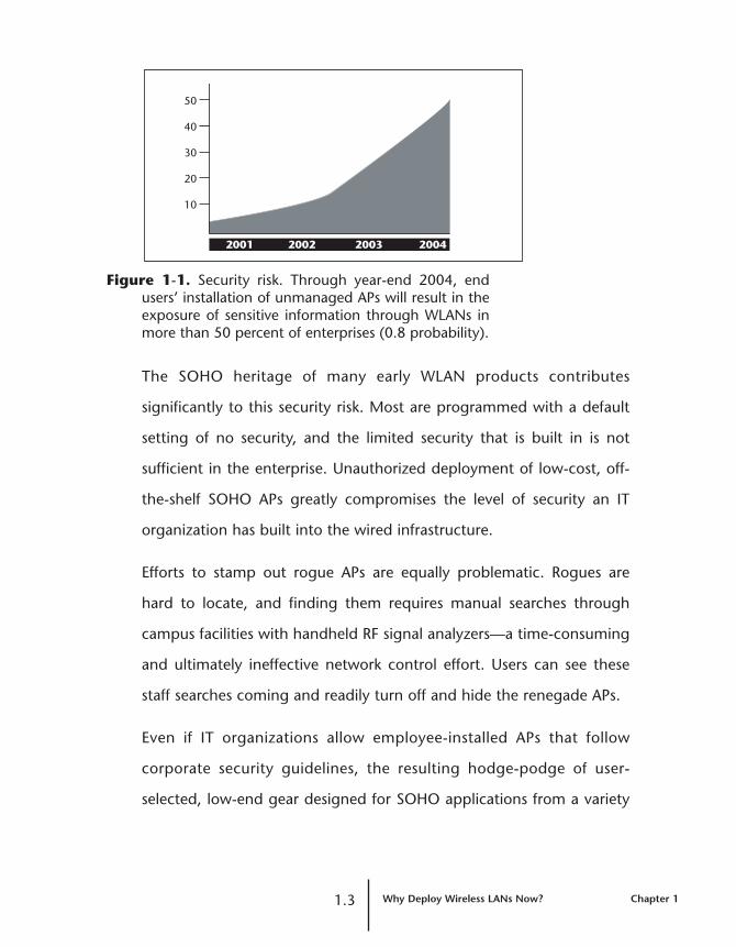
Figure 1-1. Security risk. Through year-end 2004, endusers’ installation of unmanaged APs will result in theexposure of sensitive information through WLANs inmore than 50 percent of enterprises (0.8 probability).
The SOHO heritage of many early WLAN products contributes
significantly to this security risk. Most are programmed with a default
setting of no security, and the limited security that is built in is not
sufficient in the enterprise. Unauthorized deployment of low-cost, off-
the-shelf SOHO APs greatly compromises the level of security an IT
organization has built into the wired infrastructure.
Efforts to stamp out rogue APs are equally problematic. Rogues are
hard to locate, and finding them requires manual searches through
campus facilities with handheld RF signal analyzers—a time-consuming
and ultimately ineffective network control effort. Users can see these
staff searches coming and readily turn off and hide the renegade APs.
Even if IT organizations allow employee-installed APs that follow
corporate security guidelines, the resulting hodge-podge of user-
selected, low-end gear designed for SOHO applications from a variety
1.3 Why Deploy Wireless LANs Now? Chapter 1
2001 2002 2003 2004
10
20
30
40
50

of vendors lacks the management, scalability, integration, or secure
mobility required for the enterprise.
Making the Choice
With such strong user demand for WLANs, IT organizations must have
a strategy. Three major choices have emerged for how to approach
wireless in the enterprise:
• No wireless deployment—trying to persistently eradicate all wirelessdeployments
• Small pilot projects—rolling out limited coverage for a small user set
• Doing it right—initiating an enterprise deployment
No Wireless Deployment
Taking the “just-say-no” approach will not succeed because it is
impossible to enforce. Recent studies have shown that most enterprises
have rogue AP deployments, and without the tools to be RF aware—
tools that a WLAN implementation can offer—those rogues will
continue to go without detection. So just saying “no” to wireless is not
only a policy that is difficult to enforce, it’s irresponsible not deploy the
WLAN tools for rogue detection.
Without implementing a WLAN with integrated rogue detection
capability, the manual resources needed to detect rogues are high, and
the process is intensely time-consuming, driving up network operating
costs. Surveillance must be frequent enough to effectively stop
unauthorized APs as they appear. Reliance on a total ban can lead IT
organizations to mistakenly assume they are successfully avoiding
Chapter 1 Why Deploy Wireless LANs Now? 1.4

wireless security holes. Some enterprises have set a zero-tolerance
policy that mandates immediate dismissal for anyone who installs a
rogue AP. However, this type of strict policy might not be enforced if a
vice president or CEO installs the rogue.
Because users will ultimately find a way to implement a tool that makes
their jobs easier, IT managers must take action to avoid losing control.
For example, despite security risks, users deployed desktop modems
until IT organizations finally provided modem pools.
Small Pilot Projects
Deploying a pilot WLAN for a limited group of users is almost as
difficult as the “just-say-no” approach. Even when the IT organization
expands the coverage area and broadens the scope of deployment,
users without access will become resourceful and find a way to obtain
access on their own.
Modest WLAN deployments can mask problems that surface only when
the installation grows. As the coverage area, user count, and
performance needs increase, an IT organization is confronted with
challenges well beyond overcoming the initial security risk. An IT
manager who does not plan for enterprise use from the start will face a
host of scalability problems, including trying to make a homogeneous
system out of a collection of miscellaneous APs.
Wireless Deployment—Doing it Right
To deploy secure WLANs effectively, IT organizations need a
1.5 Why Deploy Wireless LANs Now? Chapter 1
designable, scalable, enterprise-class system with the proper tools:
• Tools that reduce the complexity and cost of time-consuming site surveys
• Tools for understanding the RF environment as it changes
• Strong security features that allow roaming, but do not require complex new protocols or discrete appliances
• Hardware and software that complement and integrate seamlessly into the wired infrastructure already in place
• Features that leverage the existing network engineering, including wired network security, ACLs, class of service (CoS) and route policies.
Planning
A positive wireless experience for an enterprise-class network requires
IT planning to meet user expectations. Over the past few years, IT
organizations have migrated user connections from shared to switched
media. Users are now accustomed to the high-performance, switched
Ethernet connections that dominate wired desktop links. They have
come to expect bandwidth to be free, plentiful and instantaneous, and
they have specific expectations about how business applications
perform. Moving from a switched to a shared environment requires
careful planning for capacity that supports each user’s applications. The
primary applications mobile users want—including access to file
servers, email, customer relationship management (CRM) and
enterprise resource planning (ERP) applications, and the Internet—
work well in a wireless system that is designed properly. To avoid
frustrating users who have higher bandwidth demands, IT managers
must provision sufficiently when designing WLANs.
Chapter 1 Why Deploy Wireless LANs Now? 1.6

Budgeting
IT organizations need to budget appropriately for wireless adoption.
WLAN integration into a wired infrastructure increases networking
costs initially, but a phased approach that meets enterprise
requirements keeps the costs manageable. In the long term, a system
that simplifies growth and other aspects of operation greatly reduces
total cost of ownership for the WLAN.
In contrast, waiting to deploy a WLAN is likely to increase the total cost
of ownership. IT organizations must search for rogues and patch
security breaches in the interim, and replace inadequate APs when they
do roll out a bona fide corporate system. As reliance on WLANs
increases, the cost and complexity of moves and changes for mobile
workgroups is dramatically reduced, compared to the costs for wired
users.
Doing It Now
IT organizations can take control of WLANs to deliver user flexibility,
mobility, and productivity benefits throughout the corporate
enterprise. But to do so, they must deploy a system that truly meets the
enterprise requirement for management, scalability, integration, and
secure mobility. Wireless is here to stay. Early adoption will help avoid
the headaches, costs, and risks of waiting. The time is now.
1.7 Why Deploy Wireless LANs Now? Chapter 1

Chapter 1 Why Deploy Wireless LANs Now? 1.
2.1 What Type of Wireless LAN Chapter 2is Best for the Enterprise?
Chapter 2
What Type of Wireless LANis Best for the Enterprise?
Deploying an enterprise-class wireless system is the best way to avoid
the disruption caused by unauthorized 802.11-based WLAN
deployments. This proactive approach meets user demands, alleviates
security threats, and lays the groundwork for a scalable, cost-effective
WLAN installation.
Unfortunately, the current crop of wireless products for enterprise
deployment falls short in the critical areas of security, integration,
performance, and planning.
Problems with Add-Ons
Security remains the most significant concern for IT managers
considering a WLAN deployment. (See Chapter 3, “Is Secure Mobility
Possible in a Wireless LAN?”) News stories detailing the gaps in wireless
security abound in both business and trade news publications. The
trouble spots are well documented: WLAN equipment ships with
default settings that disable security, the minimal security standards are
easily spoofed, and rogue APs are easy for users to deploy and hard for
IT to detect.

Significant System Change
Some vendors have designed purpose-built appliances to deliver single
functions, such as security, mobility or rogue detection. But these add-
ons present their own challenges. Many require IT organizations to
make substantial changes to the core network, client devices, or both.
Some products require IT to learn new protocols and install them on all
edge routers. Other architectures mandate the installation of software,
such as virtual private network (VPN) client code, on each laptop to be
used on the wireless system.
Still other solutions require all wireless users to be in a single VLAN,
making obsolete any existing network engineering done with wired
VLANs. And some products depend on complicated deployments of
network address translation (NAT), in many cases breaking current
implementations of NAT and undoing critical security mechanisms such
as ACLs based on IP source addresses, or protections against denial-of-
service (DoS) attacks.
Poor System Integration
These layered approaches, in which IT staff adds one piece of
functionality at a time to WLANs, highlight the incompleteness of
today’s wireless system. Their lack of maturity forces IT managers to act
as network integrators and painstakingly try to combine products from
several vendors in an effort to get the required feature set. The
resulting WLAN is neither well integrated itself, nor integrated tightly
with the existing wired infrastructure.
Chapter 2 What Type of Wireless LAN 2.2is Best for the Enterprise?
Inadequate System Protection
In addition to forcing IT organizations to change their existing network
engineering policies and structures, add-ons fail to help IT address
wireless issues such as rogue detection. (See Chapter 4, “Can a Wireless
LAN Prevent Rogue Intruders?”) Delivering secure mobility across
subnets, supporting VLANs in the air, and delivering the power of
business applications and services to the mobile enterprise workforce
need not require a redesign of the network.
Coverage plus Capacity
Wireless users are focused on gaining access to vital business
applications, file servers, email, and the Internet while working
anywhere—not just at their desks. However, users won’t be happy if
throughput slows to a trickle. Recent corporate IT upgrades from
shared to switched media at the network edge have raised user
expectations to the high-performance network experience that
switched 100 Mbps desktop links provide.
As wireless deployments increase, the minimal “Can-you-hear-me-
now?” approach to delivering only coverage won’t work. Instead, IT
organizations must plan for capacity by designing a WLAN that ensures
enough bandwidth for each mobile user. (See Chapter 5, “Capacity vs
Coverage: Can this Complex Design Challenge Be Solved?”) Enforcing
CoS over WLANs does not guarantee performance, so IT managers
must understand the impact that the shared infrastructure will have on
certain applications.
2.3 What Type of Wireless LAN Chapter 2is Best for the Enterprise?
IT organizations must also take care not to accidentally create a
performance bottleneck by using appliances to solve the wireless
problems of security and mobility. Most appliances that provide secure
roaming are traditional servers that throttle performance, because they
must process all wireless traffic. Other systems provide only basic
connectivity information—simply telling users whether or not they’re
attached to the network. This information yields no insight into the
actual throughput of the connection.
Cohesive Network Planning
In wired networks, most network engineering tools are based on
geography and physical devices. Subnets are assigned to router or
switch ports, VLANs belong to specific subnets, and ACLs and multicast
protocols reside on routers.
Because wireless networks require user mobility, network attributes can
no longer be based on physical ports or device location. To enable
consistent VLAN and subnet membership, to apply appropriate ACLs to
users, and to deliver multicast services, the entire network must be
planned as one cohesive system, supporting network policies that span
the wired and wireless domains. Cohesive policies cannot be delivered
across the network if the WLAN is managed as a separate infrastructure
from the wired LAN.
The Dreaded Walkabout
A major shortcoming in today’s wireless systems is the lack of planning
tools to help IT organizations determine where to start this
overwhelming process of implementing the WLAN.
Chapter 2 What Type of Wireless LAN 2.4is Best for the Enterprise?
The first step most IT managers undertake when initiating a wireless
investigation is to partner with a team that can perform a site survey.
The process of walking around the campus to determine RF signal
strength and propagation is costly and time consuming, and the
survey’s accuracy is short-lived. The walkabouts do not significantly
reduce the trial and error associated with placing APs within the facility,
and do not ensure that the installed WLAN meets the objective set
during the site survey. Site surveys also cannot help reconfigure
existing APs to accommodate new ones as they’re needed to support
WLAN user growth.
Fundamentally, today’s wireless devices provide no RF awareness or
management tools. (See Chapter 8, “How Can Wireless LANs be
Planned and Managed?”) With no ability to see the air, IT personnel
can’t verify AP channel assignments, prevent configuration errors, set
AP power levels, measure system capacity, or verify signal coverage
without patrolling the building with a handheld analyzer, taking a hit-
or-miss snapshot approach to locating and isolating rogue AP
deployments, tracking user locations, and measuring performance
bandwidth.
Effective AP Architecture
Some vendors have attempted to overcome this shortfall of planning
tools by adding more intelligence to their APs, sparking a heated
industry discussion about fat vs. thin APs.
Proponents of fat APs argue that more intelligence is needed in the AP
to get network services, such as improved security, closer to the users.
2.5 What Type of Wireless LAN Chapter 2is Best for the Enterprise?
Other vendors insist that thin APs, with little software intelligence, are
cheaper and easier to deploy on a broad scale.
A simplistic discussion about the evolution of AP architecture misses the
balance that an effective design must meet. (See Chapters 6 and 7, “Is
One AP Architecture Best for the Enterprise?”) The integrated AP design
—one based on a cohesive WLAN mobility system—would offer
enough functionality to deliver the necessary RF awareness (thus
avoiding the dreaded walkabout) and participate in encryption and
security, but not be hampered by unnecessarily complex software,
require local configuration, or retain so much user and network
information that it becomes a security risk.
Enterprise-Class Scalability
A system designed to meet the needs of security, integration, planning,
and management in an enterprise organization is essential to scalable
WLAN deployments. IT managers need a complete system that lets
them avoid the integrator role. The system must incorporate planning
and management, and must integrate with the wired infrastructure to
form a single network with multiple media types. IT staff must be able
to leverage existing network engineering work without changing core
or client equipment and software. And the WLAN system must deliver
enterprise mobility without compromising security.
IT organizations chartered with meeting user demand for mobility
need to look beyond the current crop of piecemeal products in their
search for an integrated mobility system. Nothing less will scale.
Chapter 2 What Type of Wireless LAN 2.6is Best for the Enterprise?

3.1 Is Secure Mobility Possible in a Wireless LAN? Chapter 3
Chapter 3
Is Secure Mobility Possible ina Wireless LAN?
Concerns about IEEE 802.11 WLAN security are preventing many IT
directors from deploying large-scale WLANs. Adding mobile wireless
clients and APs to the network infrastructure knocks holes in the
network’s carefully constructed security perimeter. Designing a secure
WLAN by not allowing mobility eliminates the primary benefit of
wireless networking.
A WLAN can be both secure and mobile. Without mobility, a WLAN is
nothing but wire replacement. Without security, a WLAN is
unacceptable to any corporation. With secure mobility, a WLAN
becomes an integral element of the corporate network, enabling users
to be productive no matter where they are.
Some secure mobility solutions force IT managers to significantly
change their network backbones to accommodate mobile WLAN users.
Other solutions require users to significantly change their client
configuration and logon behavior, which becomes a challenge to IT
training, administration, and technical support. What’s needed is a
secure mobility solution that seamlessly integrates the WLAN with the
wired LAN and allows key network attributes to be associated with the
user’s identity, rather than with physical switch ports as in today’s wired

networks. That way, secure mobility is inherent in the WLAN system
architecture, enabling users to move securely with a minimal impact on
IT administration.
Secure Mobility: A Paradox
While mobility is the number one driver for wireless networking,
ensuring secure mobility isn’t a simple equation.
Secure Networks Aren’t Mobile
The problems of 802.11 WLAN security are well documented. Static
WEP keys, which secure the communication between the wireless client
and the AP, are shared across different users associated with an AP. A
savvy hacker can crack a static 128-bit WEP key with off-the-shelf tools
in a couple of hours. As a result, the IEEE developed new solutions for
access control and encryption.
New Standards Provide Security, not Mobility
The IEEE 802.1X task group was formed to authenticate users for
network access control, and the IEEE 802.11i task group was formed to
improve and standardize wireless encryption. 802.11 mandates the use
of 802.1X for authentication purposes. The 802.1X standard includes
the Extensible Authentication Protocol (EAP), which permits the use of
several authentications protocols (for example, EAP-Transport Layer
Security (TLS), Protected Extensible Authentication Protocol (PEAP),
and Tunneled Transport Layer Security (TTLS)) to control network
access. The new 802.11i standard for encrypting the wireless
Chapter 3 Is Secure Mobility Possible in a Wireless LAN? 3.2
transmissions between clients and APs will supercede WEP. The 802.11i
standard offers two choices for encryption:
• Temporal Key Integrity Protocol (TKIP) addresses WEP’s known
vulnerabilities and provides per-packet key mixing, a message
integrity check, and a re-keying mechanism.
• Advanced Encryption Standard (AES) is a new cryptography
algorithm from the U.S. government that will deliver the strongest
possible encryption, replacing the data encryption standards 3DES
and DES.
In October 2002, the Wi-Fi Alliance announced a certification process
for Wi-Fi Protected Access (WPA), which is an industry-supported, pre-
standard implementation of 802.11i that uses TKIP. WPA will serve until
the 802.11i standard is ratified the third quarter of 2003, with chip
vendors supporting the AES specification shortly thereafter. WPA
certification testing is scheduled to begin in the first quarter of 2003.
With WPA-certified products, you can build a WLAN that is secure but
not mobile. Suppose you want to give wireless access to the marketing
department. You set up 802.1X using dynamic WEP keys for
encryption, or WPA, for the users in marketing and put them in the
marketing VLAN or subnet. Now the marketers can have wireless access
as long as they stay within the wireless marketing VLAN. If they walk
down the hall to the finance department, or anywhere another subnet
is wired to the APs, marketing users no longer have access to the
marketing subnet and, because they are unable to keep the same IP
address as they roam, their active sessions break.
3.3 Is Secure Mobility Possible in a Wireless LAN? Chapter 3

Current Mobility Options Are Flawed
To add mobility to a WLAN today, IT managers can follow these
options:
• Put all wireless users on the same VLAN or subnet, and force all
wireless users to be routed to their resources.
• Use the complex Mobile IP protocol, which requires a new routing
protocol on all edge routers and a special proxy service in the APs.
• Create a service set identifier (SSID) per VLAN on all APs and bridge
all those various subnets to every AP using 802.1Q trunking.
These mobility options all have two inherent flaws. First, they are not
aware of a user’s identity. Second, all these techniques have a large
impact on configuration and deployment of the existing wired
backbone infrastructure.
While each of the above-mentioned approaches adds mobility to a
WLAN, IP security (IPsec) VPNs have been the most widely
implemented by early adopters to address security. For a VPN to
maintain its connection, the user session must retain the same IP
address as the user moves from AP to AP. To support this architecture,
either the network must have all wireless users on the same VLAN, or
the IT manager must put every VLAN everywhere. Client VPNs also
don’t scale easily, because of the cryptographic load they place on the
VPN server and the significant client configuration required.
Mobile Networks Aren’t Secure
In a wired network, the IT manager knows the locations of all user
Chapter 3 Is Secure Mobility Possible in a Wireless LAN? 3.4
devices and the switch ports they are connected to. In a wireless
network, as users move from AP to AP, the IT manager doesn’t know
the physical locations of users without significant effort. Securing a
network that mobile users move around in, enter, and leave is
not trivial.
APs Can Create Risks
APs themselves have security implications, because they must sit in
physically insecure locations. A malicious user can temporarily remove
an AP from a desk, wall, or ceiling and obtain its security configuration,
including authentication servers and encryption settings. Or the
intruder can easily replace the AP with his or her own hardware for
subsequent access to the corporate backbone from a wide area,
including the parking lot.
APs with console ports for local management are also a security risk.
The only port on a well-designed AP should be for the LAN connection.
Another security hole occurs if an AP has its own IP address. A malicious
user can manipulate such an AP to mount a DoS attack. Every AP with
an IP address or console port represents a target. Finally, these types of
APs can simply be stolen, reconfigured and used elsewhere.
How Traditional Networks Implement Security
Traditionally, networks have depended on physical connectivity as part
of their security implementation. The traditional tools for security and
traffic isolation—VLANs, subnets, ACLs, and route policies—depend on
the physical connectivity of clients to a switch or router port. The same
3.5 Is Secure Mobility Possible in a Wireless LAN? Chapter 3

is true for traffic management tools, such as CoS or even IP multicast
protocol functionality.
If a user can access the network from a given port, the switch or router
accepts the traffic. At Layer 2, VLANs are assigned to physical ports on
a switch within a subnet. At Layer 3, a subnet is configured on a router
port and corresponds to a physical area of the network (for example,
the third floor of Building 2). For more fine-grained access control, IT
managers set up ACLs, which are rules applied to traffic crossing a
Layer 3 switch or router. Route policies control forwarding between
subnets attached to a particular router.
QoS or CoS criteria enable IT managers to establish rules for prioritizing
traffic at the router or switch by marking traffic with its priority level as
it’s received on the port. IP multicast protocols used for streaming
video are enabled on a router for the attached subnets as well.
Network operating systems like Microsoft’s NT Domain or Active
Directory take a user-centered view. After a user logs into a server with
a username and password, NT Domain or Active Directory verifies
(authenticates) the user’s identity. As a direct result of authentication, a
user gains access rights (is authorized) based on a username or group
membership. In many instances, users are authenticated through an
authentication server like Microsoft’s Internet Access Server (IAS). In
addition, IT managers can account for users’ consumption of network and
server resources for billing purposes (accounting). This process is referred
to as authentication, authorization and accounting or AAA (“triple A”).
Chapter 3 Is Secure Mobility Possible in a Wireless LAN? 3.6

WLANs Break the Model
WLANs break the model for network device and network operating
system security. WLANs highlight the difference between network
device and network operating system security and demand that they
become aligned with a basis on the user’s identity. Whereas network
device security depends on user connections to physical ports or
devices, wireless users are mobile—they move from AP to AP. Location
and port identification per user is no longer effective in the WLAN for
network security. User identity is the one attribute that can be used to
employ security regardless of user location and mobility.
If network security is integrated with AAA and based on user identity,
then the network is constantly aware of each user’s physical location.
Having the ability to track the location of users as they roam on the
WLAN is necessary for detection of rogue APs and ad hoc users, and for
establishing roaming policies for authorized users. (For more
information about rogue APs and users, see Chapter 4, “Can a Wireless
LAN Prevent Rogue Intruders?” )
In practice, the most secure and mobile WLANs function at multiple
layers, with a user-identity perspective rather than a port, device, or
location perspective. With the right architecture, IT managers can be
assured that users have the right authentication and encryption
settings, VLAN or subnet membership, roaming policy, and QoS
priority, regardless of location.
3.7 Is Secure Mobility Possible in a Wireless LAN? Chapter 3

Today’s Landscape for Secure Mobility
Without a secure mobility solution based on user identity, users have to
log in multiple times, be re-authenticated, and obtain a new network
address as they roam. Alternatively, Identity-Based secure mobility
allows each user a single, persistent login for their network session. This
avoids the need to re-authenticate on the network and prevents
subsequent application interruption, regardless of where the user may
roam on the WLAN.
The first requirement of secure mobility is seamless integration into the
existing wired infrastructure. Many of the techniques for secure
mobility implemented by current WLAN vendors revive problems that
plagued wired networks in the past. These techniques include creating
a single flat VLAN for wireless clients, deploying a complex new
protocol—Mobile IP—through the network, putting every VLAN
everywhere or forcing users to run IPsec VPNs over the WLANs.
One Flat VLAN—An Imprecise Tool
The most common solution to the secure mobility problem has been to
put all WLAN users into a single VLAN, which creates a wireless “walled
garden” for security. A user has one subnet or VLAN membership when
wired, and a second different VLAN membership when mobile.
Although VLANs are a good solution for traffic engineering, they are an
imprecise tool for security. Consider some effects of the flat VLAN
solution:
• Too many users. As the WLAN becomes more popular, the IT
Chapter 3 Is Secure Mobility Possible in a Wireless LAN? 3.8
manager must move more users into the wireless VLAN. Eventually,
all users are grouped in a single flat VLAN and subnet.
• One large subnet. A single wireless VLAN has significant
administrative consequences for an IT organization. The backbone
router and distribution switches must be reconfigured to enable the
new wireless VLAN presence everywhere. Router-based ACLs
between existing subnets become useless, because all the wireless
users are now on the same subnet. Users cannot be organized into
different broadcast domains, which is particularly problematic on
bandwidth-constrained WLANs.
• Undifferentiated access. Once users are in the same VLAN, it is
more difficult to differentiate access privileges, with no distinction
among the CEO, a financial analyst, and a contractor.
Mobile IP—Complex and Ineffective
Mobile IP is touted as a secure mobility solution for several markets
ranging from mobile wireless carriers to small enterprises. Mobile IP, a
set of RFC, or “request for comment,” standards for performing
mobility across the Internet, is a complex solution that has significant
performance and scalability problems. Although the first Internet
Engineering Task Force (IETF) standards for Mobile IP date back to
1995, the protocol is not in widespread or large-scale deployment. The
following factors explain why:
• Mobile IP uses a confusing triangle routing scheme.
Every roaming user utilizes a home agent and a foreign agent router.
As the user roams from the home subnet, the traffic is first tunneled
from the foreign agent to the home agent and then routed to its
ultimate destination. Return traffic to the user is routed back through
3.9 Is Secure Mobility Possible in a Wireless LAN? Chapter 3
the foreign agent care-of address. The resulting routing data paths,
which form a triangle and in which a single outage can widely affect
connectivity, make troubleshooting difficult.
• Mobile IP requires special software installed on routers
and clients or APs.
All edge routers require significant configuration changes and
possible upgrades. Few IT managers want to add new software to
clients because of the time and cost required. The Gartner Group
estimates a $250 cost every time IT touches a user’s PC. As a result,
Mobile IP is more commonly supported by special Mobile IP proxy
software installed in each AP rather than directly in each user.
• Mobile IP exposes critical operations on APs.
Implementing the Mobile IP proxy and other system-level
functionality requires putting router-based operating system
software into APs. This effectively turns each AP into a mini-router.
An AP is not designed to be a router, because it lacks a router’s
horsepower, fault tolerance, and physical security. This design can
expose to attack dozens of APs running Mobile IP proxy software out
in the open on each floor of an office—all performing critical
network functions.
• Mobile IP can have a considerable performance impact on
the routers.
Every roaming user results in a tunnel being formed between a home
agent and a route entry in both routers’ route tables. The size of the
Chapter 3 Is Secure Mobility Possible in a Wireless LAN? 3.10

route tables expands as the number of roaming users increase. As
the Mobile IP deployment grows, edge routers are likely to require
an upgrade, adding considerable capital and labor expense.
• Mobile IP has significant scaling problems.
When using Proxy Mobile IP, each AP must propagate home agent
router information for all users across all APs in the network. As users
roam, these small devices must quickly make and break tunnels for
each user so that application sessions are maintained. In addition,
the home agent routers in the network must set up, track, and tear
down per-user tunnels for every move the user makes.
• Mobile IP can create a single point of failure for WLAN
users.
In a Mobile IP network, one AP designated as the “authoritative AP”
is responsible for propagating the table of user IP addresses and their
home agent routers. As a result, one AP in an insecure location
becomes a single point of failure for all mobile users. Designating a
secondary authoritative AP involves another redundancy protocol.
Normally a critical network function like this would be locked in a
wiring closet—with a backup—not hanging from the ceiling or wall.
• Setting up QoS, CoS and IP Multicast.
An IT manager must configure QoS or CoS parameters for each of
possibly hundreds of APs in an enterprise WLAN. The efficiency of
streaming protocols can be severely reduced. With Mobile IP, every
3.11 Is Secure Mobility Possible in a Wireless LAN? Chapter 3

roamed user requires a duplicate IP multicast stream, which can
overwhelm the network.
VPN Tunnels—Inconvenient and Vulnerable
VPNs are often used to create secure tunnels. All roaming users must
first go through a VPN server, which typically uses IPsec or the Point-to-
Point Tunneling Protocol (PPTP) to create the tunnels. Here are some of
the results:
• Bottlenecks. Forcing all users to go through one device to roam
creates a bottleneck. VPN protocols were designed for 56 Kbps dial-
up speeds, not the performance of 802.11b or 802.11a WLANs,
which is measured in several megabits per second. Although many
WLAN VPN servers use a distributed architecture to ease the
performance bottleneck, putting multiple boxes at the edge of the
network adds significant capital and labor expenses.
• Multiple logins. Because many VPN servers require an additional
login, a user must log in once to the network and a second time to
the wireless VPN—just as users do with dial-up VPNs. This process is
an inconvenience begging to be circumvented. Moreover, delay-
sensitive applications such as voice over wireless IP (VoWIP) do not
work if users are forced to re-authenticate.
• Vulnerable local data. A lesser-known but critical issue is that
VPNs often do not secure localized access on clients. A user with a
VPN connection from a laptop through an AP can communicate
securely to a VPN server, but another user communicating with the
same AP can access any local drive open on the laptop. To prevent
this, an additional piece of client software is required, usually in the
form of a personal firewall.
• Vulnerable APs. Some vendors have implemented the VPN server
directly into their APs. Many APs with an integrated VPN server also
Chapter 3 Is Secure Mobility Possible in a Wireless LAN? 3.12

store the database of usernames and passwords locally. The result is
a considerable security risk, because critical network security
elements are located out in the open among users and visitors.
Two New Secure Mobility Approaches
Because existing secure mobility solutions have been widely recognized
as problematic, WLAN vendors have come up with newer options. One
approach is to deploy the existing VLANs by creating an SSID for each
VLAN. Another is to deploy appliances on every subnet, with WLANs
and a centralized controller to deliver secure mobility. These methods
also have advantages and disadvantages.
SSID per VLAN
A recent development in mobility solutions is to create an SSID for
every VLAN. An SSID is a common name used across APs in an 802.11
network. An IT manager might create an SSID for marketing, another
for finance, and another for guests, all on the same AP.
Lack of IT Control
Although this approach appears simple, it creates a VLAN free-for-all,
because the IT organization cannot control the VLAN to which a user
connects. Success depends on trusting the user to choose the right
SSID and type the correct syntax. Users who choose wrongly, or enter
the wrong syntax, connect to the wrong VLAN—intentionally or
accidentally.
For example, although User 1 belongs in the marketing VLAN, IT can’t
force her to log into that VLAN. She is free to enter the SSID for any
3.13 Is Secure Mobility Possible in a Wireless LAN? Chapter 3

other VLAN, such as finance. Operating systems like Microsoft
Windows XP allow users to see and select the available SSIDs if the
WLAN is configured to transmit beacons. For example, Windows XP-
Service Pack 1 searches for another advertised SSID, which is typically
the “guest” SSID. If she selects this SSID, User 1 attaches, unencrypted,
to the guest VLAN, is unable to access the corporate resources she
needs, and advertises local shared files on her hard drive. If beacons for
other SSIDs are disabled, IT must trust users like User 1 to type the SSID
correctly to access the network, a situation that can generate technical
support calls. An IT manager can’t count on consistent client behavior,
because each service pack has different mechanisms for wireless
network search and user control.
Network Inefficiency
Perhaps even more significant are the changes to the network
backbone that SSID-based VLANs require. IT managers must pre-
configure 802.1Q-tagged VLANs throughout the backbone to all APs
where users need to roam, effectively making all VLANs run
everywhere. For example, if a network has 16 VLANs, the IT manager
must configure all 16 tagged VLANs on each router port that extends
through the wiring closets and out to all APs. That means a 16-fold
increase in the control traffic sent over the air spectrum, significantly
impacting WLAN performance. In addition, configuring all VLANs
everywhere defeats the purpose of using VLANs for traffic isolation.
IP multicast can quickly become a nightmare. If one person from each
of the 16 VLANs requests streamed video, the server sends 16 duplicate
Chapter 3 Is Secure Mobility Possible in a Wireless LAN? 3.14
streams to users who are physically located on the AP, grinding WLAN
performance to a halt.
Security Appliances
Another recent approach to secure mobility is to use appliances created
specifically to handle secure roaming. These appliances typically create
IPsec tunnels for clients to one appliance. As users roam across subnets,
their traffic goes through NAT and is forwarded back to the first
appliance. The NAT function allows the client to maintain its IP address
as it roams.
Most appliances use a two-tier architecture. An AP management
appliance resides on subnets, sitting between third-party APs and the
router. These devices handle user encryption and manage user subnet
roaming. A central controller appliance handles authentication, policy
management, and QoS priorities.
Lack of Wireless Awareness
A major drawback of these Layer 3 devices is that they do not secure
the air, because they are unaware of the WLAN. Appliances also don’t
secure the peer-to-peer communications between users on the same
WLAN. A rogue user can easily gain access to data on a mobile laptop
without being detected by the appliance.
Complex Integration
Appliances don’t seamlessly integrate into the existing infrastructure.
They typically require the deployment of IPsec software on the clients,
3.15 Is Secure Mobility Possible in a Wireless LAN? Chapter 3
which is a significant financial and administrative expense in a large
enterprise. The IT organization must reproduce any router-based ACLs
on the appliance, because the appliance ignores the existing ACLs.
Although many appliances offer QoS or CoS traffic policies, the IT
manager must set up the parameters separately from the QoS policies
that have been established for the existing infrastructure.
Don’t underestimate the difficulty of managing a large-scale NAT
solution. Appliance support for protocols such as FTP, H.323
videoconferencing, voice over IP (VoIP), and NetMeeting can vary
widely, because it depends on the appliance vendor’s specific NAT
implementation. Also, allowing guests to use their company’s own VPN
software is nearly impossible, because VPNs can’t typically handle a
second layer of NAT.
Poor Performance
Appliances also create a bottleneck. Because all users must authenticate
through the central management appliance, the total network
performance is limited by the appliance’s performance. Because most
appliances are based on PC platforms, the performance is seriously
lacking. An appliance with a 150 Mbps bus, for example, is capable of
supporting at most three 802.11a APs, which have a maximum data
rate of 54 Mbps. Any additional APs increase the traffic in the subnet
and might make an additional appliance necessary.
Chapter 3 Is Secure Mobility Possible in a Wireless LAN? 3.16

AAA Resolves the Secure Mobility Paradox
For security and mobility to co-exist, the WLAN must seamlessly
integrate into the existing wired network. The AAA model blends the
best of the user-centric and device-centric approaches.
The AAA approach to secure mobility uses information from 802.1X
client authentication to map users to their native VLAN, regardless of
where they are connected in the WLAN. This design enables IT
organizations to locate and follow users as they move, and applies
security contexts unique to each user. The AAA-based approach
provides one fundamental change—attributes such as VLAN
membership that are traditionally associated with physical ports now
follow the user, independent of the network attachment point or
medium (wired or wireless).
With the AAA solution, an IT manager can enforce VLAN membership,
encryption settings, roaming policies, and QoS priorities based on the
users’ authenticated identity. Because the AAA-based WLAN can detect
a user’s location, identifying, locating and diagnosing becomes a much
simpler task, not a complex afterthought.
Table 3-1 on the following page compares mobility solutions based on
Mobile IP, SSID per VLAN, and AAA.
Identity-Based AAA Advantages
With the AAA solution, users do not have to change their logon
behavior to go mobile. The same logon and authentication procedures
3.17 Is Secure Mobility Possible in a Wireless LAN? Chapter 3
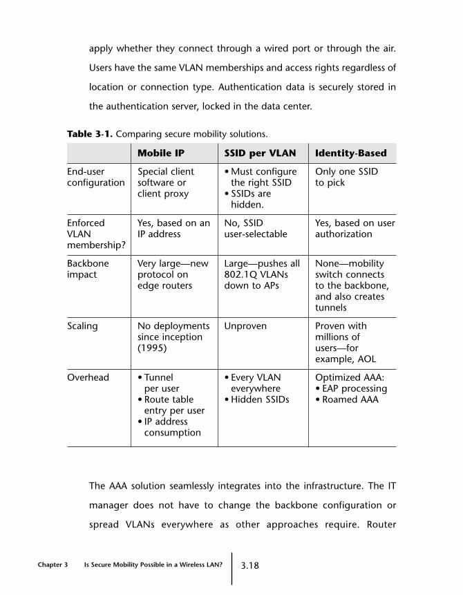
apply whether they connect through a wired port or through the air.
Users have the same VLAN memberships and access rights regardless of
location or connection type. Authentication data is securely stored in
the authentication server, locked in the data center.
Table 3-1. Comparing secure mobility solutions.
Mobile IP SSID per VLAN Identity-Based
End-user Special client • Must configure Only one SSID configuration software or the right SSID to pick
client proxy • SSIDs arehidden.
Enforced Yes, based on an No, SSID Yes, based on user VLAN IP address user-selectable authorizationmembership?
Backbone Very large—new Large—pushes all None—mobilityimpact protocol on 802.1Q VLANs switch connects
edge routers down to APs to the backbone,and also createstunnels
Scaling No deployments Unproven Proven withsince inception millions of(1995) users—for
example, AOL
Overhead • Tunnel • Every VLAN Optimized AAA:per user everywhere • EAP processing
• Route table • Hidden SSIDs • Roamed AAAentry per user
• IP addressconsumption
The AAA solution seamlessly integrates into the infrastructure. The IT
manager does not have to change the backbone configuration or
spread VLANs everywhere as other approaches require. Router
Chapter 3 Is Secure Mobility Possible in a Wireless LAN? 3.18
configurations and ACLs do not need to change or be recreated. A
subnet remains a subnet—it includes the same group of users whether
wired or wireless.
Nor do AAA solutions require changes to IP addressing. WLAN users get
their IP addresses from the same dynamic host configuration protocol
(DHCP) server, whether they are wired or wireless, and not from a NAT
appliance where the IP address constantly changes as they move.
Roaming Policies
With the AAA approach, setting and enforcing policies is part of the
authorization step. For instance, IT can consider establishing a roaming
policy. Roaming restrictions might seem counter-intuitive, because a
major benefit of a WLAN is mobility. However, the ability of users to
roam doesn’t make unlimited roaming a good idea. IT organizations
might want to establish a roaming policy for several reasons:
• Different types of users might require different levels of access. A
policy can establish that visitors or contractors are allowed to roam
only in public areas and conference rooms, but employees can roam
throughout the building.
• IT might not want to share the wireless resources in a particular area
with any other users, for security and bandwidth conservation.
Despite the technology advances, WLAN bandwidth remains a
precious resource.
User-Based ACLs
Using the AAA approach, IT managers can easily enforce access control
and CoS policies by creating user-based ACLs for individual users and
3.19 Is Secure Mobility Possible in a Wireless LAN? Chapter 3

groups. User-based ACLs are a new concept—access control rules
follow users wherever they move. For example, an IT organization
might want to create a policy that prevents guests from accessing
internal corporate resources and limits Internet access. To do so, IT can
set up a user-based ACL that permits guests to access just the Internet,
not internal IP addresses—no matter where those guests move—using
a lower QoS. Without a solution based on AAA, an IT manager cannot
implement this level of control. Other approaches use one policy to
apply to all users on a VLAN.
A secure, mobile solution must also deliver scalable corporate AAA
services for user authentication, bandwidth provisioning, and
management. An installed AAA server can increase its capacity by
offloading the front-end processing associated with 802.1X network
authentication onto WLAN devices, rather than passing them to the
authentication server.
Intelligent AAA
A solution based on AAA sounds great, but what IT organization
doesn’t run AAA today? AAA already runs on standard network
operating systems like Windows NT Domain or Active Directory. A
secure wireless solution from just about any vendor requires
standards-based 802.1X, one of the EAP authentication protocols for
wireless users, and a back-end server like Microsoft’s IAS or Funk
Software’s Steel-Belted Radius as a store for authentication and
authorization information.
Chapter 3 Is Secure Mobility Possible in a Wireless LAN? 3.20

The key difference is to deploy a system that uses AAA for secure
mobility instead of only simple yes-or-no access to the network. The
system must monitor and control the location of user identity so the
security contexts of the user can move across wireless networking
devices as the user’s authenticated identity. To deliver this benefit, the
network devices must be user aware. Traditional multilayer switches
lack this capability.
AAA solutions have repeatedly been proven to support very large
deployments. In fact, AAA is probably the most used, reliable, and
scalable method of controlling access to network resources. America
Online (AOL) uses AAA to help manage its 30+ million subscribers.
Most other Internet Service Providers (ISPs) use it as well.
To support wireless needs in the enterprise, WLAN equipment can
offload back-end AAA server processing in three ways:
• By not requiring an authenticated user to re-authenticate when
roaming
• By offloading protocol processing onto the WLAN system
• By distributing authentication requests to different servers based on
organizational name or load-sharing techniques
A smart WLAN doesn’t need to prompt a roaming user for credentials
more than once and becomes even more user aware by incorporating
802.1X and EAP authentication capabilities directly into its devices.
(See Figures 3-1 and 3-2.)
3.21 Is Secure Mobility Possible in a Wireless LAN? Chapter 3

Figure 3-1. A traditional authenticator pushes a significantload to the AAA server.
Chapter 3 Is Secure Mobility Possible in a Wireless LAN? 3.22
AuthenticationServer
Authenticator Supplicant
RADIUS Access Request
RADIUS Access Challenge
RADIUS Access Request
RADIUS Access Challenge
RADIUS Access Request
RADIUS Access Challenge
RADIUS Access Request
RADIUS Access Challenge
RADIUS Access Request
RADIUS Access Challenge
RADIUS Access Request
RADIUS Access Challenge
RADIUS Access Request
RADIUS Access Accept
RADIUS Access Request
RADIUS Access Challenge
RADIUS Access Request
RADIUS Access Response
EAP Request, Identity [RFC2284]
EAP Response, Identity [RFC2284]
Request, EAP-PEAP
TLS, Client Hello
TLS, Svr Hello, Cert, CR, Hello Done
Response, EAP-PEAP
TLS, Svr Hello, Cert, CR, Hello Done
Response, EAP-PEAP
TLS, Svr Hello, Cert, CR, Hello Done
TLS Change Cipher, Encrypted handshake
Request, EAP-PEAP
TLS Cert, Client key exchange, Cert verify,
Change Cipher, Encrypted handshake
TLS Change Cipher, Encrypted handshake
Response, EAP-PEAP
EAP Request, Identity [RFC2284]
EAP Response, Identity [RFC2284]
Challenge MSChapv2
Response MSChapv2
Success, MSChapv2
Ack MSChapv2
EAP Success
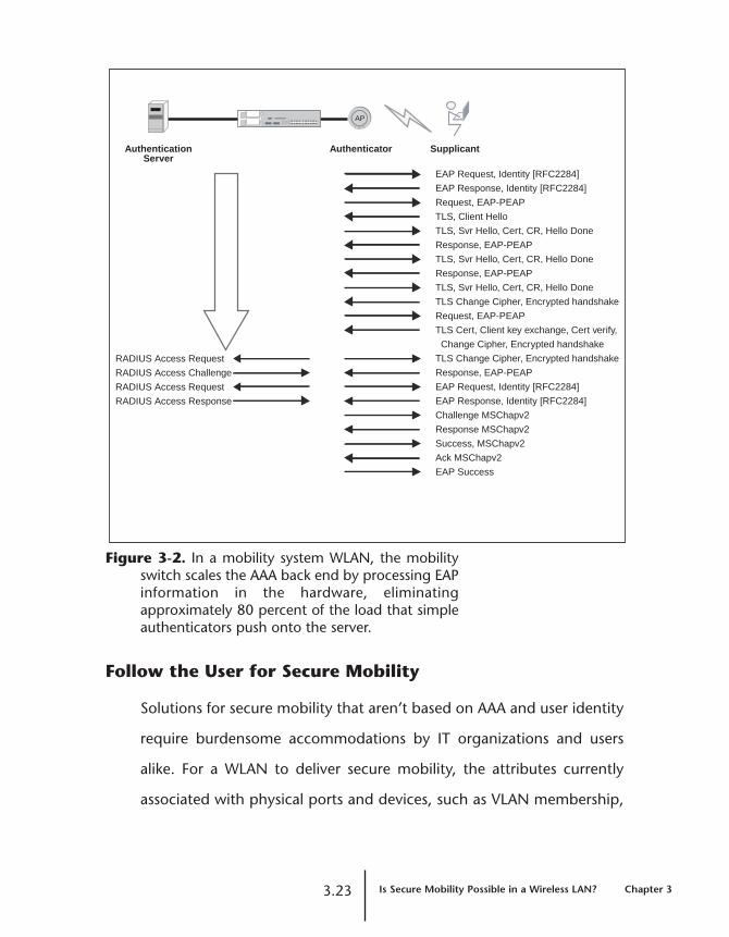
Figure 3-2. In a mobility system WLAN, the mobilityswitch scales the AAA back end by processing EAPinformation in the hardware, eliminatingapproximately 80 percent of the load that simpleauthenticators push onto the server.
Follow the User for Secure Mobility
Solutions for secure mobility that aren’t based on AAA and user identity
require burdensome accommodations by IT organizations and users
alike. For a WLAN to deliver secure mobility, the attributes currently
associated with physical ports and devices, such as VLAN membership,
3.23 Is Secure Mobility Possible in a Wireless LAN? Chapter 3
AuthenticationServer
Authenticator Supplicant
RADIUS Access Request
RADIUS Access Challenge
RADIUS Access Request
RADIUS Access Response
EAP Request, Identity [RFC2284]
EAP Response, Identity [RFC2284]
Request, EAP-PEAP
TLS, Client Hello
TLS, Svr Hello, Cert, CR, Hello Done
Response, EAP-PEAP
TLS, Svr Hello, Cert, CR, Hello Done
Response, EAP-PEAP
TLS, Svr Hello, Cert, CR, Hello Done
TLS Change Cipher, Encrypted handshake
Request, EAP-PEAP
TLS Cert, Client key exchange, Cert verify,
Change Cipher, Encrypted handshake
TLS Change Cipher, Encrypted handshake
Response, EAP-PEAP
EAP Request, Identity [RFC2284]
EAP Response, Identity [RFC2284]
Challenge MSChapv2
Response MSChapv2
Success, MSChapv2
Ack MSChapv2
EAP Success
AP

authentication policies, ACLs, and roaming policies, must follow the
user, regardless of where the user is or how he or she connects to the
network. A solution based on AAA associates those key attributes with
the user as his or her authenticated identity. When the WLAN system
can follow the user, identifying and locating rogues becomes much
simpler and more effective.
The AAA-based solution doesn’t force users to change their logon
behavior. Nor does it force IT managers to make large-scale changes to
their routed network backbones, IP addressing, or client software. In
the enterprise, ease of administration, scalability, and simplicity are
paramount. WLANs can be an integral part of enterprise infrastructure
networks, not an isolated workgroup solution, when a secure mobility
solution meets enterprise demands.
Chapter 3 Is Secure Mobility Possible in a Wireless LAN? 3.24
4.1 Can a Wireless LAN Prevent Rogue Intruders? Chapter 4
Chapter 4
Can a Wireless LAN PreventRogue Intruders?
Unsecured WLANs provide open doors to an enterprise network and its
valuable data. Mobile users armed with nothing but a laptop and a
wireless adapter can easily “drop in” on a network. These network
intruders are known as rogues.
How Real are Rogues?
Rogues are not just hackers and outside intruders “war driving”
through the parking lot with 802.11 antennas made from Pringles
cans. Most likely, they’re employees who are unaware of wireless
network usage policies. Perhaps they are experimenting with non-
enterprise-grade WLAN APs in the office, having grown impatient with
an IT organization’s pace in deploying wireless tools. Maybe they’ve
connected such an AP to the wired network, inadvertently creating a
huge security hole. In any case, corporate information is at risk, unless
the IT organization takes control.
Users love the freedom of mobility. They are not waiting for an IT
organization’s official approval to set up WLANs. Like the PC
transformation, wireless is a user-driven revolution. The Gartner Group
estimates that one in five companies has a WLAN that the CIO doesn’t
know about. (For more about the user-driven WLAN revolution, see
Chapter 1, “Why Deploy Wireless LANs Now?”)
If a company has deployed WLANs, a rogue AP can cause interference,
open a new security hole, and degrade the sanctioned WLAN’s
performance. Even a company with a wait-and-see approach to
enterprise WLANs must be prepared for unexpected rogue invasions.
Unsecured WLANs provide open doors to a corporate network and
its valuable data. In a wired network, access to the building itself,
structured wiring, and firewalls prohibit impromptu LAN connectivity.
With wireless, physical access no longer provides the most basic line
of security.
To control unsanctioned WLANs, IT organizations need the right tools
to detect and locate rogue users and APs. Rogue detection is essential
to maintaining network security, preventing the loss of critical data and
intellectual property, and avoiding potential liability. Today the process
is time-consuming, requiring an IT manager to walk around looking for
rogues. Rogue detection can be expensive, forcing IT organizations to
buy an add-on network of rogue AP sensors. Fortunately, the ability to
detect and locate rogues is becoming an integral part of enterprise
WLAN systems.
Identifying Rogues
The first step in protecting network resources from misuse is to
determine what constitutes a rogue. While various types of threats can
occur from both authorized and unauthorized users, the following
WLAN rogues are most common:
Chapter 4 Can a Wireless LAN Prevent Rogue Intruders? 4.2
• Unauthorized network AP—an unapproved, non-enterprise-
grade wireless AP that an employee connects to the wired LAN for
wireless access
• Unauthorized standalone AP—an AP set up by a group of
employees to create a standalone wireless workgroup LAN which is
not plugged into the wired network
• Unauthorized user—a guest, intruder, or hacker who uses his or
her own wireless tools and attempts to access the WLAN from
inside the facility or from the parking lot, street, or other location
physically nearby
Unauthorized Network AP
An internally deployed unauthorized AP is the most common threat to
WLANs. For example, an employee who has an 802.11 WLAN at home
to connect his laptop, printer, and PDA decides to bring his own AP
into the office, to more easily transfer data between his office desktop
and his mobile tools. He buys an AP that’s suited for home use, at a
local electronics store. But this AP lacks the security built into an
enterprise-grade AP, such as WPA or encryption.
Because the employee is unaware that his WLAN is a threat to
corporate network security, he doesn’t seek approval from the IT
manager. Nor does he need assistance from the IT help desk, because
wireless networking at this level is plug-and-play. As a result, the rogue
WLAN goes undetected by IT staff.
Unauthorized Standalone AP
A second type of rogue is a private WLAN user group of employees
with an AP or even a “soft AP,” which is software that gives AP
4.3 Can a Wireless LAN Prevent Rogue Intruders? Chapter 4

functionality to a wireless laptop. Although their WLAN is isolated from
the enterprise WLAN, the users are stealing bandwidth in the air from
legitimate WLAN users. The private WLAN can also cause interference
to an authorized WLAN in other parts of the enterprise.
An uninvited guest who eavesdrops on the private WLAN can gain
access to the network through the employees’ wired LAN connections,
or by intercepting their usernames and passwords on the official
wireless LAN. A network breach might occur without IT staff ever
knowing about it.
Unauthorized User
Once an external rogue user has gained access to the network, he or
she can launch a man-in-the-middle attack to gain full network access
or launch a DoS attack that jams the airwaves for all users.
Unauthorized use of the network or ISP connection can also create a
legal liability for the enterprise.
An external attack is a real threat, especially if the WLAN security
settings, such as 802.1X authentication and encryption, are not
operational or configured to prevent unauthorized intrusions. A
knowledgeable intruder with an 802.11 device or other wireless access
tool can easily determine the necessary SSIDs of the WLAN and media
access control (MAC) addresses and steal the identity of an authorized
AP or users.
Such intrusions often occur when the enterprise IT manager doesn’t
change the AP’s default SSID. The defaults are common knowledge and
Chapter 4 Can a Wireless LAN Prevent Rogue Intruders? 4.4

are not hard to discover. For instance, Cisco APs use the SSID tsunami,
Linksys defaults to linksys, and Symbol defaults to 101. In this type of
intrusion, the rogue can easily log on by posing as a legitimate user or
as an AP. The intruder then has complete access to the WLAN and can
listen to the airwaves and intercept unencrypted messages. This
intrusion can remain undetected by an IT organization, because the
WLAN management system identifies the intruder as a legitimate client
or AP. Intrusion in this manner is not a difficult task for a hacker with
even a limited set of wireless intrusion tools and minimal skills.
Risk Factors of Rogues
Once a single rogue gains network access, he or she can severely
compromise network security in a number of ways.
Unsecured Holes in the Network
Although a wired network might be a walled fortress guarded by
multiple firewalls, a WLAN is much more vulnerable. A single rogue
wireless user can gain entry, bypassing the firewalls and opening the
floodgates for others to come in and access corporate data. An AP that
is suitable for home use, not enterprise use, can still have an IP address
and console port to facilitate remote configuration and management. It
might have an embedded DHCP server and be able to assign IP
addresses. APs with console ports and embedded DHCP servers are
vulnerable to reconfiguration and malicious use elsewhere.
4.5 Can a Wireless LAN Prevent Rogue Intruders? Chapter 4

Potential Loss of Private Data or Intellectual Property
Once a rogue has penetrated a network, the door to the private data
network has been opened and the information security line has been
breached. For the CIO or IT manager, that means sensitive system data,
such as passwords and policy information, is no longer secure.
Confidential corporate information stored anywhere on the network
can be accessed or downloaded.
Legal Liability for the Enterprise
Unauthorized use of the network or the Internet connection is a legal
liability for the enterprise, not for the rogue user. If the rogue user
distributes illicit or illegal materials over the Internet from an
enterprise’s unsecured WLAN, that enterprise is held liable—not
the rogue.
Denial of Service to Legitimate Users
A rogue who launches a DoS attack can disrupt throughput and
performance in the airspace. Jamming the WLAN with data packets
forces clients to continuously disconnect from and reconnect to
legitimate APs, effectively knocking them off the network.
Man-in-the-Middle Attacks
In this type of attack, a rogue attracts a user at authorization time, or
jams a legitimate AP and forces the user to re-associate with the rogue.
A man-in-the-middle rogue AP is very difficult to detect and is
potentially very damaging, because it grants full network access to
the rogue.
Chapter 4 Can a Wireless LAN Prevent Rogue Intruders? 4.6

A man-in-the-middle rogue AP makes a PEAP-TLS Part 1 connection to
a corporate AP, masquerades as a client, and trivially authenticates the
corporate AP. This first step of this attack results in an encrypted TLS
session between the rogue and the authenticator. Next, the rogue AP
acts like a bug light, attracting legitimate clients and requesting TLS
authentication. The rogue tunnels the TLS authentication exchange
between the legitimate user and the authentication server. The system,
unaware of the rogue, completes the authentication process of PEAP-
TLS Part 2. Once the legitimate user is authenticated, the rogue can
derive the session encryption keys, which are based on information
exchanged in the original PEAP-TLS Part 1 phase. The rogue
disconnects the legitimate user and turns its bug light off.
The rogue now has complete, undetected network access. The
authentication server was unable to detect the rogue user. The
legitimate user retries authentication, connects to a corporate AP this
time, and is authenticated. Other than a slight delay in authentication,
which might be attributable to temporary RF interference, the user is
unaware of its manipulation by the rogue.
Wired and WLAN Performance Degradation
Whether a rogue launches a man-in-the-middle or DoS attack, or a user
inadvertently steals the air from legitimate users, enterprise network
performance and throughput can suffer. Once a rogue is on an
enterprise network, it can consume even more precious shared
resources, such as the Internet connection. The rogue can steal
4.7 Can a Wireless LAN Prevent Rogue Intruders? Chapter 4
intellectual property, post salaries on the Internet, or steal the launch
plans for a company’s next new product.
Undetected Rogues in the Wired Enterprise
Detecting and locating rogues is a challenge for WLAN systems,
because the requirements for security in a WLAN are different from
the security requirements of the operating systems and devices in
wired networks. These differences require WLAN system vendors to
address rogue identification and detection as an integrated part of
their solutions.
A traditional network operating system has no mechanism to detect or
locate rogue users, on either the wired or wireless LAN. The network
operating system employs usernames and passwords to authenticate
and authorize users, but doesn’t monitor where users and devices are
physically located once they are authenticated. Network devices such
as switches and routers base their security on the physical connection
between the user’s device and the switch or router port. Port security is
enforced by device MAC address or 802.1X authentication on a wired
switch port. Some switches are capable of reporting when
unauthorized MAC addresses are detected on the LAN. Today, these
primitive methods are the only possible means of rogue detection
currently available in a wired network.
Once users are mobile, they are no longer connected to a specific port
on a switch. Yet, port security is predicated on a physical connection.
Legitimate wireless users move—and so do rogues. The network
Chapter 4 Can a Wireless LAN Prevent Rogue Intruders? 4.8

operating system can’t detect the move. Nor can a wired Intrusion
Detection System (IDS) or Simple Network Management Protocol
(SNMP) management application detect a rogue user or AP, because
these tools lack awareness of the air.
External Tools for Rogue Detection
To detect a rogue user or AP, IT organizations have two choices. IT staff
can carry out a regular manual analysis of the WLAN by walking around
the building with a wireless device loaded with scanning or analysis
software. Or an IT organization can install an IDS of rogue AP sensors.
For either method, external tools are available.
WLAN Scanners and Analyzers
Several scanning tools are available to capture the 802.11 packets of
WLAN transmissions. For example, NetStumbler and AirSnort can scan
the airwaves for WLAN signals, list what is available, and reveal their
descriptors and vital statistics.
WLAN analyzers are another choice. Usually selling in the $1500 to
$4000 range, products such as AirMagnet’s AirMagnet, WildPackets’
AiroPeek, and Sniffer Wireless can capture 802.11 packets, analyze the
Layer 1 and Layer 2 information, and report transmission data such as
signal strength and channel and data rates. Some analyzers require
expert WLAN network and security analysts to understand the data and
locate the threats detected. Typically available in both laptop and
handheld formats, these tools usually can’t pick up signals from
microwaves or portable telephones operating in the same spectrum
4.9 Can a Wireless LAN Prevent Rogue Intruders? Chapter 4
that can also cause interference. In contrast, a spectrum analyzer can
resolve channel conflicts between 2.4 GHz cordless phones and
a WLAN.
The manual approach to rogue detection is time-consuming, requiring
IT staff to walk around the building performing WLAN packet analysis
on an ongoing and regular basis. Manually policing the building or
campus for rogue users is an unreasonable burden for IT staff.
In addition, the process of manual scanning and analysis is not
particularly accurate. Although this approach might help IT discover
some vulnerabilities in the network, the odds of locating a rogue who is
on the WLAN at the exact moment when an IT manager is conducting
a sweep are slim. Because these tests provide only a random sample of
the airwaves, a rogue can log on only seconds after a sweep and go
undetected. A rogue user can typically see that a sweep is taking place
and temporarily turn off and hide the rogue device.
Installed Wireless Intrusion Detection Systems
Continuous monitoring of the airwaves requires even more expensive
wireless intrusion detection tools, such as AirDefense. Similar to an IDS
for a wired network, a wireless IDS requires a network of sensor APs to
monitor the production WLAN for rogues. The sensor APs cannot carry
enterprise network traffic. Once a rogue is detected, the sensors use
triangulation techniques to locate the rogue. Without intimate
knowledge of the facility layout and the enterprise WLAN architecture,
the IDS can have difficulty pinpointing the location of a rogue AP or user.
Chapter 4 Can a Wireless LAN Prevent Rogue Intruders? 4.10
Because wireless intrusion detection tools typically start at $25,000 for
a minimum installation, round-the-clock rogue detection quickly
becomes a costly add-on if a WLAN system vendor doesn’t integrate
support for rogue detection and location. A better approach is to
deploy a WLAN system that is inherently able to detect and locate all
APs and users and easily distinguish legitimate APs and users from
unauthorized ones.
Advantages of Built-In 802.1X Authentication
Although expensive analysis and monitoring tools can help detect
rogue users and APs, implementing 802.1X with AAA, strong
encryption and an EAP method that is not vulnerable to a man-in-the-
middle attack, such as Microsoft Challenge Handshake Authentication
Protocol (MS-CHAP) version 2 or EAP-TLS, is the best defense. If only
authenticated users can communicate on the network and all
communication is encrypted, the chances are small that a rogue can
penetrate and do damage. By using the features of 802.1X, AAA and
encryption, an IT organization can severely limit if not completely
eliminate rogue attacks in the enterprise.
List of Legal Users
Because mobile users are not always associated with the same AP,
access control must be based on the user’s identity. Setting up 802.1X
authentication by user or group for a company severely limits the ways
in which a rogue user can penetrate the network. The 802.1X
authenticated users, along with all the authorized APs on the WLAN,
4.11 Can a Wireless LAN Prevent Rogue Intruders? Chapter 4
constitute a dynamic “legal users” list. With this list it becomes easy for
IT staff to identify rogue users and APs.
Mutual Authentication
Authentication must be a mutual process, in which the network
authenticates the user and the user authenticates the network. Mutual
authentication ensures that the user doesn’t accidentally join a rogue AP.
An intruder cannot use an unsecured AP to gain access to a corporate
network, because all users must authenticate the network, as well as be
authenticated before gaining access to corporate resources. A rogue AP
has a much harder time attracting and authenticating users, because
the user demands strong authentication from the rogue AP, as well.
Using 802.1X authentication completely integrates the detection of
rogue APs and users into the network system, rather than overlaying an
expensive and complex system specifically to identify rogues.
Authentication Server Implementation
Authentication by means of the 802.1X framework is best implemented
with a Remote Authentication Dial-In User Service (RADIUS) server,
either separately or as a part of Microsoft Windows NT Domain or
Active Directory. Either way, centralized 802.1X authentication is one of
the best ways to effectively manage WLAN usage and prevent rogues.
Although it is typically used in a WLAN, 802.1X running in both the
wireless and wired networks brings stronger authentication to the
entire enterprise. Defense against rogues becomes an integral part of
the WLAN system, not an expensive and complex after-market add-on.
Chapter 4 Can a Wireless LAN Prevent Rogue Intruders? 4.12
To Catch a Rogue: Location, Location, Location
Detecting a rogue is not enough. An IT organization must be able to
locate a rogue to stop it. Some vendors recommend complex
approaches, such as triangulating a rogue’s location with a Global
Positioning System (GPS), which doesn’t work reliably indoors (where
an office WLAN is typically located). The best solution lies in knowing
the locations of all APs and wireless users and being able to distinguish
authorized users from unauthorized ones.
RF Topology Maps
To locate rogues, the WLAN system must have an accurate and
thorough map of the RF topology. WLAN system tools must recognize
the facility’s physical attributes, such as the locations of the walls and
floors. The WLAN system must be able to detect where all its APs are
located—and map them to the floor plans.
RF Sweeps
WLAN system software must be able to perform regular RF sweeps of
the WLAN domain. During a sweep, each AP listens across every
channel for RF activity to determine who’s using the air and who’s
connected. Listening across all channels, not just on the channels
actively transmitting, is critical, because a rogue might be quietly
hiding on another channel. Some rogue detection methods rely on
listening only to beacons. Smart hackers turn off beaconing when
trying to penetrate a network.
4.13 Can a Wireless LAN Prevent Rogue Intruders? Chapter 4

An RF sweep provides the IT organization with a complete view of all
802.11 APs and devices, whether legitimate or not. From this
information, the WLAN system can determine which APs and users are
rogues and which are approved and authenticated. If it detects a
rogue, the system can triangulate the known physical location of the
APs to determine the rogue’s location. The WLAN system can use RF
signal strength to help IT staff identify the device in question.
Once they confirm the presence of a rogue, IT staff can narrow the
scope of the RF sweep and perform it again, or use a WLAN analyzer to
look for the illegal device.
Common Sense
Detecting rogues is an inexact science. IT managers need to be wary of
rogue-detection tools that offer automatic control or shutdown.
Rogue-detection tools are rarely, if ever, able to exercise any control
over the rogue. Breaking encryption keys is virtually impossible,
because of the improvements to WLAN security. Identifying the brand
of a rogue AP and its operational commands is difficult for anyone
other than the AP vendor. The goal of rogue detection is to quickly
detect, locate and remove the rogue AP, and not to knock off a
legitimate but unrecognized user, such as a guest who didn’t properly
log on to the network.
Chapter 4 Can a Wireless LAN Prevent Rogue Intruders? 4.14
Rogue Prevention in a WLAN System
Determining a rogue’s location within an enterprise WLAN can be
difficult and expensive. To build the best defense against rogues:
• Know what constitutes a rogue in the network and how to identify
rogue usage on a WLAN.
• Make sure everyone in the IT organization is aware of the risk factors
associated with rogue users and APs.
• Know how to fully implement authentication and encryption tools,
including 802.1X, dynamic WEP, WPA, and 802.11i.
• Make 802.1X authentication with AAA the cornerstone of WLAN
access control in both wired and wireless networks.
• Require vendors to provide rogue detection tools as part of the
WLAN system.
4.15 Can a Wireless LAN Prevent Rogue Intruders? Chapter 4

Chapter 4 Can a Wireless LAN Prevent Rogue Intruders? 3.16
5.1 Capacity vs. Coverage: Can this Complex Chapter 5
Design Challenge be Solved?
Chapter 5
Capacity vs. Coverage: Can this Complex DesignChallenge be Solved?
Designing enterprise WLANs is a new craft, even for many experienced
IT organizations. Most IT managers can plan sufficient capacity for the
users and applications in a wired network. However, in IEEE 802.11
WLAN design, a new factor comes into play: distinguishing between
designing merely for RF coverage versus designing for network
capacity. For an IT organization attempting to determine the number
and placement of APs in a WLAN, planning for both capacity and
coverage is a key design challenge.
Enterprise users accustomed to high-speed, full-duplex 100 Mbps
switched networks expect similar performance from their shared WLAN
connections. The important question for enterprise WLAN designers is
how to deliver enough bandwidth to meet the demands of business
applications, not how far the RF signal can travel. Planning for optimal
capacity automatically guarantees complete coverage.
Existing manual methods for determining WLAN capacity and coverage
are laborious and time-consuming for IT organizations.
Planning WLAN Capacity for the Enterprise
Many IT organizations mistakenly focus on providing adequate
coverage for their users, rather than the required bandwidth capacity.
Although coverage might be the primary goal in a WLAN based on a
single AP for a conference room or a workgroup, the application
demands of an enterprise network make bandwidth capacity the
critical design criterion. A WLAN designed for coverage alone will not
deliver enough bandwidth. In addition, WLAN designers must account
for the shared nature and growth of the network.
Accounting for Shared Connections
WLANs provide shared, not switched, connections. The first structured
wiring implementations were a shared medium and congestion
problems drove a migration from shared to switched wired networks.
But WLANs are shared networks by nature, because the air cannot be
switched.
This difference makes WLAN design more difficult. Users expect
applications to be as responsive on a WLAN as on a switched Ethernet
network, but they also want the benefits of wireless mobility. A shared
wireless network must be designed to deliver the mobility demanded
by users and the application responsiveness they have come to expect.
Using a Structured, Scalable Design Method
Successfully designing a WLAN requires more than a one-time site
survey to check RF coverage. WLAN design requires the same
structured, scalable approach that IT managers apply to their wired
networks, which ensures that sufficient capacity—as well as coverage—
is available to users.
Chapter 5 Capacity vs. Coverage: Can this Complex 5.2Design Challenge be Solved?

Typically, the first step in planning an 802.11 WLAN is a site survey. An
IT manager walks around an office that has an AP installed, using a
wireless-enabled laptop or PDA with site survey software to measure
the RF signal strength. Once he or she tabulates the collected data—a
tedious process at best—the IT manager can calculate the number and
locations of APs required. Site surveys are something of an art, and
many enterprises must rely on system integrators for assistance.
This approach simply doesn’t scale. WLAN management tools must
come into play that allow the IT manager to design, plan and verify AP
installation and manage those APs from a central management interface.
Factors Affecting WLAN Capacity
APs are the communication hubs of WLANs, linking mobile wireless
devices to network services. Key factors to consider when planning
WLAN capacity include the RF coverage of each AP in the WLAN and
the bandwidth required to support the user population. Designing
smaller coverage areas – or cells – with higher throughput can create
an enterprise-quality experience. Other factors to consider are the
bandwidth required for user applications, the achievable (as opposed
to theoretical) throughput, the effects of signal loss and interference,
and the differences between 802.11a and 802.11b technologies.
RF Coverage of an AP
An IT organization can establish the RF coverage of each AP in a WLAN
by determining the diameter of the AP’s service range. Because data
rate is a function of distance, the farther a user is from the AP, the
5.3 Capacity vs. Coverage: Can this Complex Chapter 5
Design Challenge be Solved?

weaker the signal and the lower the data rate. The data rate a WLAN
achieves depends on its wireless standard and the distance of a user
from an AP:
• 802.11a WLANs. The 802.11a standard is so new that detailed
measurements on coverage are scarce. However, 802.11a radio
manufacturers anticipate a data rate of 36 Mbps within a 23-meter
(75-foot) radius. Users must be in very close range—within 3
meters (10 feet)—of an AP to maintain the maximum data rate of
54 Mbps.
• 802.11b WLANs. Networks using the 802.11b standard have a
maximum data rate of 11 Mbps within a radius of 30 meters (100
feet) when indoors.
These data rates are theoretical. For actual rates, see “Achievable
Throughput” beginning on page 5.8.
Effect of Association Data Rate on Throughput
Many APs have an auto-step feature that automatically decreases the
data rate at which a user can associate with it. As the user moves
farther from the AP, the RF signal degrades. An 802.11a AP with this
capability is expected to step down from 54 Mbps to 36 Mbps, 24
Mbps, 12 Mbps, and finally 6 Mbps. Similarly, an 802.11b AP typically
steps down from 11 Mbps to 5.5 Mbps, 2 Mbps, and finally 1 Mbps.
Figure 5-1 shows how the association data rate of an AP decreases as
the RF coverage increases.
Chapter 5 Capacity vs. Coverage: Can this Complex 5.4Design Challenge be Solved?

Figure 5-1. 802.11 data rates are highest closest to the AP.Many APs automatically decrease their associationdata rates as the user moves farther from the AP.Network designers can set a minimum associationdata rate to deliver more bandwidth to all users.
5.5 Capacity vs. Coverage: Can this Complex Chapter 5
Design Challenge be Solved?
23m (75')
100m (300')
48 Mbps
6 Mbps
9 Mbps
12 Mbps
18 Mbps
24 Mbps
36 Mbps
54 M
30m (100')
100m - 150m (300' - 500')
1 Mbps
2 Mbps
5.5 Mbps
11Mbps
802.11b
802.11a

IT organizations can take advantage of the auto-step feature.
Mandating a minimum association data rate improves the overall
experience for all users and enables a more efficient deployment of
multiple cells. One user associated at 1 Mbps slows down an entire cell.
Because the AP takes longer to communicate with the 1 Mbps user,
bandwidth is reduced for all other connected users. Setting 5.5 Mbps
as the lowest allowable association rate for an 802.11b network, for
example, forces users to associate with a new AP if their signal quality
degrades below that threshold.
Cell Size to Accommodate User Density
The number of users and their applications are major drivers of
bandwidth requirements. The WLAN design must account for the
number of users within the AP’s cell diameter. In a large, open office
with a high user density, where walls and other objects do not naturally
define the cells, designing smaller cells can achieve a higher data rate.
Smaller cells can reuse frequencies more often and thus ensure that the
channels do not overlap. Figure 5-2 shows how the use of smaller cell
sizes on an 802.11b WLAN in a 100-user office increases throughput
and improves the user experience.
Chapter 5 Capacity vs. Coverage: Can this Complex 5.6Design Challenge be Solved?

Figure 5-2. In a 100-user office, smaller cells achieve a higherthroughput for more users. Smaller cells can reusefrequencies more often to minimize inference.
5.7 Capacity vs. Coverage: Can this Complex Chapter 5
Design Challenge be Solved?
11
1
6
100 users per office11 Mbps peak 802.11b3 APs per office17 Mbps total throughput
1
11
11
6
6
100 users per office11 Mbps peak 802.11b5 APs per office55 Mbps total throughput

In most enterprise-class APs, transmit power settings can be adjusted to
change the cell size. But depending on the implementation, that
adjustment can be an arduous manual task, rather than a simple one.
Application Bandwidth Needs
Determining how much bandwidth each user needs is critical, because
these calculations define the user experience as well as the number of
APs required. A good rule of thumb for an 802.11a network is to allow
for 2 Mbps downstream and upstream (4 Mbps total) per user, which
delivers about the same user experience as a wired LAN. For an
802.11b network, a rule of thumb is to allow for 500 Kbps each way (1
Mbps total), which delivers a user experience similar to a broadband
DSL connection.
Bandwidth estimates must account for the impact of user applications
on radio activity. Radio activity occurs when data is transmitted and
received by the user. For example, reading a web page entails no radio
activity. However, a large application for ERP or CRM requires many
interactions between the clients and servers and much radio activity.
Achievable Throughput
IEEE 802.11 systems are time-division duplexed. Upstream and
downstream communications use the same frequency over the air and
thus cannot occur simultaneously. For 802.11a networks, the 54 Mbps
data rate is split between upstream and downstream traffic. For
802.11b networks, the downstream and upstream traffic flows share a
total of 11 Mbps.
Chapter 5 Capacity vs. Coverage: Can this Complex 5.8Design Challenge be Solved?

Several factors reduce the achievable throughput on a wireless system
to a rate much lower than the technology’s specified data rate. One
factor is overhead from the media-access control method in 802.11
networks, called carrier sense multiple access with collision avoidance
(CSMA/CA). In CSMA/CA, a client ready to transmit determines
whether the transmission medium is busy before it sends. If the
medium is busy, the client waits a random amount of time before
attempting to resend. In addition, even if the medium appears to be
clear, a collision might occur because not all clients can monitor all
other clients. Collisions cause additional throughput decline. Devices
using 802.11a have other sources of inefficiency, including orthogonal
frequency division multiplexing (OFDM) modulation, in which only
48 of the 64 tones are used for data and the rest are used for
protocol overhead and signal protection. Error-correction coding adds
further overhead.
When all these effects are combined, the net result is to reduce
achievable throughput to approximately 50 percent of the theoretical
data rate. For instance, with even a one-way transmission on a 54
Mbps system, the best possible throughput is approximately 30 Mbps.
For an 802.11b network, the best possible throughput is 4 Mbps to
6 Mbps.
Signal Loss and Interference
A major difference between designing for wired LANs and WLANs is the
RF signal loss caused by attenuation from walls, doors, windows, and
other fixed objects in a building. Concrete walls absorb more signals
5.9 Capacity vs. Coverage: Can this Complex Chapter 5
Design Challenge be Solved?

than plaster. Even an office aquarium soaks up signals, as do the people
in the building.
Calculating RF signal loss is an inexact science, but common sense
applies. For instance, a cloth cubicle partition has less attenuation than
a concrete wall.
When building an 802.11b network, avoid placing APs within a few
feet of devices that transmit within the same 2.4 GHz frequency, such
as the microwave oven in the lunchroom or any 2.4 GHz cordless
telephones or Bluetooth devices. An 802.11a network has fewer
interference problems.
Choosing between 802.11a and 802.11b Technology
The 802.11 specification includes an alphabet soup of standards, with
two technologies, 802.11a and 802.11b, to choose from as the
fundamental WLAN standard. The 802.11g standard will be another
option when it is finalized.
The 802.11b standard, which is currently more widely deployed,
features a raw data rate of 11 Mbps and a range of 100 feet at that
data rate. The 802.11a standard, which will be widely supported in
2003, offers a peak throughput of 54 Mbps and has a higher
throughput at similar ranges than 802.11b. For an enterprise
environment, 802.11a is likely to be the better choice because of its
higher throughput and larger number of non-overlapping channels.
Table 5-1 summarizes the advantages and disadvantages of 802.11a
and 802.11b.
Chapter 5 Capacity vs. Coverage: Can this Complex 5.10Design Challenge be Solved?

Table 5-1. Comparison of 802.11a and 802.11b capabilities.
802.11a 802.11b
Raw data rate Up to 54 Mbps Up to 11 Mbps
Achievable 20 Mbps to 30 Mbps 4 Mbps to 6 Mbpsthroughput
Association rate 54 Mbps, 48 Mbps, 36 Mbps, 11 Mbps, 5.5 Mbps,auto-step levels 24 Mbps, 18 Mbps, 12 Mbps, 2 Mbps and 1 Mbps
9 Mbps and 6 Mbps
Range 23 meters (75 feet) @ 36 Mbps 30 meters (100feet) @ 11 Mbps
Spectrum range U-NII and ISM 5 GHz to 6 GHz ISM 2.4 GHz to 2.4835 GHz
Modulation type OFDM Direct-sequence spread-spectrum (DSSS)
Non-overlapping Up to twelve Threechannels
Advantages • High data rate • Widespread• Higher spectral efficiency so product
more data can be transmitted availabilityover a smaller amount of • Low costbandwidth
• Resistance to multipath or reflected signals
• Relative immunity to interference
Disadvantages • More expensive components • Lower data rate• High power consumption • Interference from
other 2.4 GHzdevices, such as microwave ovens and 2.4 GHz cordless phones
• Fewer available channels for frequency reuse
5.11 Capacity vs. Coverage: Can this Complex Chapter 5
Design Challenge be Solved?
For regulatory reasons, not all 802.11 technologies are currently
available worldwide. Within the European Union, 802.11a is not
universally accepted, and it competes with Broadband Radio Access
Network (BRAN) HiperLAN2, an alternative standard that the European
Telecommunications Standards Institute (ETSI) ratified in February
2000. Japan allows the use of a smaller band that permits the use of
only four 802.11a channels.
Many organizations probably already have some 802.11b networks,
whether or not officially sanctioned by the IT staff, and will likely soon
have 802.11a. The 802.11a and 802.11b technologies can co-exist
peacefully. Dual 802.11a/802.11b adapter cards and APs are already
available. Enterprise WLANs are likely to use 802.11a in all new
implementations, with 802.11b for guest access and existing WLANs.
Manually Determining WLAN Capacity and Coverage
With the foregoing design factors in mind, an IT organization can
determine the number and placement of APs in a WLAN to ensure
optimal capacity and coverage. This process is complicated and time-
consuming when performed manually:
1. Determine the area or areas in which WLAN coverage is needed.
2. Define the size of each area.
3. Determine the number of users in each area.
4. Estimate the total bandwidth needed to serve the area.
5. Define a minimum data association rate at which the system must
function to achieve the estimated bandwidth in the area.
Chapter 5 Capacity vs. Coverage: Can this Complex 5.12Design Challenge be Solved?

6. Compute the number of APs needed to provide enough bandwidth
for the area.
7. Determine the number of APs needed for area coverage.
8. Place and configure the APs.
Defining Coverage Areas and Area Size
IT staff must define the areas of the enterprise in which WLAN coverage
is needed. An office building can be divided into multiple sections for
planning. Departments with bandwidth-intensive applications, such as
engineering, are best planned separately from departments with less
intensive office applications, such as sales and marketing. Hot-spot
areas such as conference rooms need to be planned separately from
the rest of the enterprise, because they have different requirements for
access and QoS.
IT staff can then define the size of each area by multiplying its width
and length.
Determining Area Users and Expected Bandwidth
After counting the number of uses in an area, IT staff can calculate the
expected total bandwidth needed to serve the area. This calculation
involves the expected number of users and throughput, and the
specifics of the 802.11 protocol.
Defining a Minimum Data Rate
Once it knows the expected total bandwidth for an area, IT staff can
define a minimum over-the-air rate at which the system needs to
function. Some locations might exceed the baseline rate, but IT must
5.13 Capacity vs. Coverage: Can this Complex Chapter 5
Design Challenge be Solved?

design for the baseline data association rate. For enterprise-style
deployments, a good rule of thumb is to set the baseline data
association rates at 11 Mbps for 802.11b and 36 Mbps for 802.11a.
Using Capacity to Compute APs
IT staff can compute the number of APs required to meet the
bandwidth requirements of a given service area, with the following
equation:
(bandwidth x number of users x % activity rate per user) ÷
(% efficiency x baseline association rate per AP) =
number of APs needed
The % efficiency value is the overall overhead efficiency factor of the
network, including MAC inefficiency and error correction overhead.
For example, a medium-size call center using 802.11b technology
wants to provide 500 Kbps of bidirectional data for 100 employees.
The activity rate per user is high throughout the day. The company
wants the maximum association rate per AP—for 802.11b technology,
the rate is 11 Mbps within 30 meters (100 feet) of the AP—and the
network is running at 50 percent efficiency. When bandwidth is
multiplied by 2 for bidirectional data, the equation yields the following
result:
Chapter 5 Capacity vs. Coverage: Can this Complex 5.14Design Challenge be Solved?
(1 Mbps) x 100 x 25%
5.5 Mbps
25 Mbps
5.5 Mbps
Always round up the total to the next whole number to ensure
adequate capacity. In this example, five APs are needed to meet the
capacity demands of the call center’s wireless network.
Using Coverage to Determine APs
After IT has computed the number of APs required for each area based
on capacity, they can also calculate how many APs are required for
adequate coverage. The extent of an AP’s coverage at a particular
association data rate is based on the sensitivity of the receiving device
and the transmission power of the AP.
Determining the distance that a particular AP can reach requires a
propagation model for computation of a link budget. Much of the
information about propagation in cellular and personal
communications service (PCS) devices is useful for indoor APs. Free-
space loss can be an accurate factor for determining propagation in
many environments at short distances.
5.15 Capacity vs. Coverage: Can this Complex Chapter 5
Design Challenge be Solved?
= 4.5 = 5
(500 Kbps x 2 bidirectional BW) x (100 users) x (25% activity rate)
(50% efficiency) x (11 Mbps baseline association per AP)= # of APs
= # of APs

Based on the transmitter power, the receiver sensitivity at the desired
over-the-air bit rate, and the desired operational link margin, IT staff
can compute the extent of coverage from a particular AP and
determine the number of APs required to cover the area. This
computation must take into account any physical obstacles in the path
from transmitter to receiver which shrink the coverage area of a
particular AP.
For most high-speed enterprise deployments, the number of APs
required for proper capacity is greater than the number required for
coverage alone. For example, based on coverage calculations, the
medium-size call center in the previous example can cover its square
footage with three APs. However, because the resulting cell sizes are so
large, some users are probably associating at 1 Mbps or 2 Mbps, a data
rate that slows down all traffic. The per-cell throughput would then be
approximately 5 Mbps. The resulting aggregate throughput for the
three-cell system would not be 3 x 11 = 33 Mbps, but more likely 3 x 5 =
15 Mbps. In contrast, the five-cell system determined by capacity
calculations has fewer users per AP, all associating at 11 Mbps to
provide 5 x 11 = 55 Mbps, a significant improvement.
Positioning and Configuring APs
Once an IT organization knows the number of APs required, it can
place them appropriately in the coverage area and configure their
channel assignments. Adjacent APs must use non-overlapping
channels. The 802.11b technology provides three non-overlapping
channels, while 802.11a offers eight or more, depending on the
Chapter 5 Capacity vs. Coverage: Can this Complex 5.16Design Challenge be Solved?

country. Channel overlap between floors must be considered in a
multistory building.
Many enterprises install APs on the ceiling to provide a clearer path and
to increase security and control. Placing APs on the ceiling puts the signal
above cubicle walls, off users’ desks—and away from curious hands.
Finally, IT staff can fine-tune the network to verify that the channel and
transmit power choices adequately cover the area. Lowering an AP’s
transmit power or setting the transmit power appropriately allows
other APs to reuse frequencies and reduce co-channel interference.
Certain brands of APs allow the transmit power to be easily modified
from the default (typically maximum) value.
Where are the Automated Tools?
Today, designing and deploying a WLAN requires time-consuming,
manual analysis. IT managers must demand enterprise-quality design
and management tools for their WLANs—the same types of tools that
are available for wired networks. Quality WLAN design tools can assist
IT staff with the design parameters, including building size and
topology, obstacles, throughput per user, country of operation, and
choice of 802.11 technologies. The tools can automatically assess
how many APs are needed, their locations, and appropriate settings.
Automated tools will save IT managers lots of time, money, and
headaches and enable them to more easily deliver an enterprise-
quality WLAN.
5.17 Capacity vs. Coverage: Can this Complex Chapter 5
Design Challenge be Solved?
How the Workflow Would Change
How would the workflow change for an IT manager attempting to plan
for adequate capacity across a WLAN if he had an automated tool?
First, he imports electronic files of the floor plans for the site where he’s
supporting a new WLAN.
The floor plan shows all the building structures, and by simply clicking
on the appropriate material make up of the structures, the tool
calculates the resulting attenuation factors for those structures. In a
matter of minutes, from his desktop, the IT manager has successfully
characterized RF behavior for his entire site, without a manual
walkabout and without intensive training in RF performance.
Next, he outlines various coverage areas where he wants to provide
access to the WLAN. He defines the user count and desired bandwidth
per user for each area, and then the tool would take over, applying the
RF attenuation factors it calculated based on building materials,
determining the number of APs needed to meet the performance needs,
placing them on the floor plan, and calculating the appropriate power
levels and channel assignments to avoid co-channel interference.
The Result is in the Bottom Line
These steps alone can dramatically reduce the total cost of ownership
(TCO) for designing and deploying WLANs. A small site plan which
might have cost approximately $5500 in site survey and IT manager
time will cost just under $300 with this kind of sophisticated tool.
Chapter 5 Capacity vs. Coverage: Can this Complex 5.18Design Challenge be Solved?

In addition, these savings apply just to the design phase. The same kind
of automated tool would also vastly simplify deployment. Once the
configuration for each AP is known, it could push that data directly to
those devices, doing away with the hours needed to link to each AP
separately to provide it with its appropriate channel and power settings.
And the same simplification helps when making updates to the wireless
network. Increasing the user count, changing the performance metrics,
or increasing the WLAN’s reach in the company will all require more
planning. With an automated tool, these changes would take just
minutes, updating the channel and power settings and pushing the
new configurations to each device automatically.
Fundamentally, any network manager confronted with the challenge of
deploying an enterprise-class WLAN cannot meet this challenge
without the help of an automated tool. Rather than a “nice to have”
feature, such a tool becomes a prerequisite to planning, deploying,
scaling, and managing a WLAN.
Designing Capacity into the WLAN System
IT managers are accustomed to designing networks for enterprise-class
application performance, and this same structured, scalable approach
needs to be applied to WLANs as well. Although both RF coverage and
capacity are key design criteria, designers must realize that designing
for capacity rather than coverage is critical to delivering enterprise-
quality throughput.
5.19 Capacity vs. Coverage: Can this Complex Chapter 5
Design Challenge be Solved?

To calculate capacity as well as coverage, designers must consider key
WLAN issues such as the number of users, the types of applications, RF
signal loss factors, and whether to choose 802.11a or 802.11b
technology, or 802.11g when it becomes generally available. Today’s
painstaking, labor-intensive calculations will be unnecessary as
automated tools come to market to help network managers successfully
plan WLAN rollouts and assist them with ongoing management.
A WLAN is not a collection of individual APs, but rather an entire
enterprise system. The WLAN system must scale to meet enterprise
demands, ensuring high throughput, secure mobility, and seamless
integration with the wired network.
Chapter 5 Capacity vs. Coverage: Can this Complex 5.20Design Challenge be Solved?
6.1 Secure and Manageable: Is One AP Chapter 6
Architecture Best for the Enterprise?
Chapter 6
Secure and Manageable: Is One AP Architecture Bestfor the Enterprise?
Must an IEEE 802.11 AP be a highly intelligent device? Or can an AP be
little more than a radio-for-wire media converter? This little device,
attached to the ceiling or wall, has ignited an industry-wide debate on
whether the most effective APs are “fat” or “thin.” Fat APs control
WLAN functions, while thin APs rely on a centralized central controller.
Confining the debate to fat vs. thin oversimplifies AP architecture. A
third type of “fit,” or integrated, AP puts intelligence in the network
infrastructure.
This chapter evaluates AP architectures for enterprise security and
management. For more information, see Chapter 7, “Scalable,
Effective, Resilient: Is One AP Architecture Best for the Enterprise?”
Fat vs. Thin
At the heart of the debate about AP architecture is whether critical
WLAN functions such as user authentication, encryption, and AP
configuration are better centralized at an intelligent control point or
distributed to the APs.

Fat APs
The traditional AP architecture uses fat APs. These standalone devices
handle all WLAN functionality, from the 802.11 radio to 802.1X user
authentication, wireless encryption, secure mobility, and management.
Many fat APs also handle critical network functions like routing, IP
tunneling, 802.1Q trunking, NAT, and VPN creation. Although a typical
enterprise WLAN includes dozens or even hundreds of APs, fat APs
function as independent devices. Each AP autonomously manages all
data and control frames and must in turn be managed as an
autonomous device.
Fat APs (Figure 6-1) typically connect to switch ports in the wiring
closet, preferably equipped with sufficient PoE integrated into the
closet switch, or as a separate PoE appliance or single “power brick”
power injector. If PoE is not available, a separate power supply at the
AP’s location will be necessary.
Figure 6-1. Fat APs are standalone devices responsible forall WLAN functionality. They typically connect towiring closet switch ports that are equipped with PoE.
Chapter 6 Secure and Manageable: Is One AP 6.2Architecture Best for the Enterprise?
Routed Core
Edge Routers
Wiring Closet Distribution
(Power over Ethernet)
Floor A
Floor B
(Power over Ethernet)

Thin APs
In an architecture that uses thin APs, the APs are little more than a
radio-for-wire media converter, communicating with a single
centralized intelligent control point in the network core. The intelligent
control point handles all aspects of 802.1X user authentication, wireless
encryption, secure mobility, and WLAN management. The central
controller configures and manages the APs, which cannot function
as standalone units. Figure 6-2 shows a typical example of thin AP
WLAN architecture.
The architecture of pairing thin APs with an intelligent controller device
has gained industry support recently, because it greatly simplifies
management responsibilities and can be less costly in large-scale
deployments. The controller device aggregates the APs and handles the
data and control frames entering and leaving the APs. Thin AP
architecture requires a Layer 2 data path to each AP through the
network infrastructure, because a thin AP does not have an IP address.
Figure 6-2. Thin AP architecture pairs stripped-down APs with asingle centralized central controller that sits in the network core.The controller handles the configuration and management ofthe APs, which cannot function as standalone units.
6.3 Secure and Manageable: Is One AP Chapter 6
Architecture Best for the Enterprise?
Routed Core
Edge Routers
Central Controller
Wiring Closet Distribution
(Power over Ethernet)
All VLANsfrom APs
(Power over Ethernet)
Floor A
Floor B
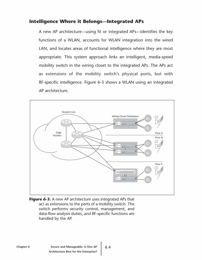
Intelligence Where it Belongs—Integrated APs
A new AP architecture—using fit or integrated APs—identifies the key
functions of a WLAN, accounts for WLAN integration into the wired
LAN, and locates areas of functional intelligence where they are most
appropriate. This system approach links an intelligent, media-speed
mobility switch in the wiring closet to the integrated APs. The APs act
as extensions of the mobility switch’s physical ports, but with
RF-specific intelligence. Figure 6-3 shows a WLAN using an integrated
AP architecture.
Figure 6-3. A new AP architecture uses integrated APs thatact as extensions to the ports of a mobility switch. Theswitch performs security control, management, anddata-flow analysis duties, and RF-specific functions arehandled by the AP.
Chapter 6 Secure and Manageable: Is One AP 6.4Architecture Best for the Enterprise?
Routed Core
EdgeRouters
Wiring Closet Distribution
Floor A
Floor B
Floor C
Distributed Intelligence
The mobility switch and integrated APs operate as an integrated
system, with the WLAN functions distributed where appropriate.
For example:
• All security-related control functions such as 802.1X authentication,
AAA integration and secure mobility are placed as close to the user
as possible while still remaining physically secure—inside the locked
wiring closet.
• All wireless traffic from an integrated AP goes to the mobility switch
for traffic isolation and filtering. This transfer is handled centrally and
at media speeds.
• The integrated APs perform packet-for-packet encryption of data
over the air, while derivation and tracking of session-specific master
keys is done at the mobility switch.
• RF data and statistics for troubleshooting and locating rogue APs and
users are provided by the integrated APs.
• All configuration and control of the integrated APs are performed by
the mobility switch. The integrated AP has no IP address, service
port, configuration information, or firmware storage.
• For QoS prioritization, traffic to the integrated APs is classified by the
mobility switch according to IP DiffServ, 802.1p, or Layer 3 and
Layer 4 policies. But the real-time treatment of when and how the
classified traffic is transmitted onto the air is handled by the
integrated APs, which use multiple CoS queues per user and are
closest to the potentially congested wireless medium.
6.5 Secure and Manageable: Is One AP Chapter 6
Architecture Best for the Enterprise?
A planning, deployment, and management tool suite allows IT
managers to gain a centralized view and control of the enterprise
WLAN and perform critical online and off-line functions.
By distributing the responsibilities of the APs and intelligent control
point, an integrated AP architecture creates a WLAN environment that
diminishes security risks and simplifies configuration and management
requirements. This architecture is scalable, improves performance, and
integrates seamlessly into the wired LAN.
Integrated WLAN Functions
Table 6-1 shows that WLAN functions in fat and thin AP architectures
are all located on either the AP or the central controller. In contrast, an
integrated AP architecture distributes WLAN functions so that the AP
and mobility switch work together in an integrated system.
Chapter 6 Secure and Manageable: Is One AP 6.6Architecture Best for the Enterprise?

Table 6-1. How functions are distributed in fat, thin, andintegrated AP architectures
Fat AP Thin AP Integrated AP
802.11 to 802.3 packet AP Central APconversion controller
Wireless encryption AP Central AP(WEP, TKIP, AES) controller
TCP/IP stack AP Central Mobility switchcontroller
Authentication control AP Central Mobility switchcontroller
Wireless-to-wireless AP Central Mobility switchforwarding controller
Stored configuration AP Central Mobility switchand image controller
Console port configuration AP Central Mobility switchcontroller
RF statistics gathering AP Central APand monitoring controller
Real-time CoS treatment AP Central APcontroller
Traffic classification for CoS AP Central Mobility switchcontroller
ACL enforcement AP Central Mobility switchcontroller
Security Consequences of AP Architecture
Security is one of the biggest concerns of CIOs and IT managers who
are considering deploying a WLAN. Much of the attention has focused
around security over the air and the ability to crack static WEP keys.
WEP weaknesses are being resolved with the introduction of the IEEE
6.7 Secure and Manageable: Is One AP Chapter 6
Architecture Best for the Enterprise?

802.11i supplement, which includes use of the 802.1X standard for
access control, and authentication and encryption technologies like
TKIP and AES.
However, the architecture of the AP itself has a significant impact on an
IT organization’s ability to secure the network and protect it against
intrusions. Security over the air is a must. What if security is completely
compromised by someone unplugging or replacing an AP, or even
simply by an uninformed user plugging in his or her own AP?
Physical Security of the AP
The office is the very definition of an unsecured environment. APs are
mounted on ceilings and walls and sometimes perched on desks and
cubicle walls. The first line of defense against physical security and
intrusion threats is to make sure that the AP architecture itself does not
create a security risk.
Fat APs—A Theft Risk
Fat APs are a significant security and theft risk. They are theft targets
because they function as standalone devices and place critical network
information like the following in the open office environment:
• Stored information about authentication servers, including their IP
address, configuration and access passwords
• Stored wireless encryption keys
• VPN or routing configurations necessary to enable secure roaming
Chapter 6 Secure and Manageable: Is One AP 6.8Architecture Best for the Enterprise?
A fat AP configuration exposes the whole network infrastructure,
revealing important information about many potential targets. Fat APs
also include a console port for configuration and management, another
glaring security hole. A well-designed AP should have only Ethernet
ports for data and PoE support.
Thin and Integrated APs—Nothing to Steal
Both thin and integrated APs offer better security because they store no
security-related information and cannot operate as standalone devices.
Physical Security of the Ethernet Link
The Ethernet connection between the AP and the wired LAN can also
be the source of a serious security problem.
Fat and Thin APs—Risky Links
In the fat AP world, the Ethernet link represents the trusted side of the
network. Yet that trusted interface is available to anyone who removes
the AP and connects his or her own device in its place. No
sophisticated attack is required.
Unfortunately, the same security problem exists in WLAN architectures
that use thin APs. Fat APs rely on common Layer 2 and Layer 3
connectivity to the network core. Thin AP architecture also requires
unencumbered Layer 2 connectivity all the way from the AP to the
central management device in the core. Those paths represent
vulnerabilities. Employees, guests, contract workers, or anyone
roaming through the office can simply remove the device and gain
access to the network.
6.9 Secure and Manageable: Is One AP Chapter 6
Architecture Best for the Enterprise?

Integrated APs—Secure Links
An architecture that uses integrated APs prevents unauthorized use of the
AP’s Ethernet link to send and receive data. A stateful link established
between the mobility switch and the integrated AP accepts only
authenticated traffic from the AP for transmission into the network core.
Security for an integrated AP is based on two fundamental principles:
• The best place to enforce security policies is as close to the user as
possible, to protect the core and distribution layers and to reduce or
prevent attacks against other edge devices or users.
• Physical security matters. Assets placed in insecure locations and the
links to them must mitigate any potential security threat or theft risk.
An integrated AP architecture balances these two principles by locating
security and policy enforcement functions in the place closest to the
user that also provides physical security: the locked wiring closet. All
other assets between the end user and the mobility switch in the wiring
closet must represent a minimal security threat and minimal theft risk.
Securing valuable data away from potential thieves or employees who
like to tinker with the network is the only solution for building a secure,
scalable WLAN. Limiting the type of network information available
from APs protects the WLAN and prevents people from accessing
network data. By storing essential network data on APs or allowing AP
removal to open a path to the network core, IT organizations can
create a gaping security threat.
Chapter 6 Secure and Manageable: Is One AP 6.10Architecture Best for the Enterprise?
Rogue Detection
The idea of a hacker with a Pringles-can antenna and an 802.11-
enabled PDA carrying out a “war drive” on an enterprise WLAN
certainly captures the imagination. However, the most likely rogue
threats come from internal users misusing the network or unauthorized
users stealing the air. (For more information about rogues, see Chapter
4, “Can a Wireless LAN Prevent Rogue Intruders?”)
Most APs, whether fat or thin, lack the horsepower to detect and locate
rogue APs and their users. To maintain their low cost, thin APs lack the
localized processing power. Fat APs are burdened with other tasks, such
as creating Mobile IP tunnels or VPN connections for secure roaming.
Moreover, fat APs lack the systemwide perspective and analysis
required for identifying rogue communication and rogue location.
Rogue detection must be handled at the APs because RF information is
required. But just listening for a rogue AP to broadcast a beacon
containing its identity is insufficient to detect rogues.
• Rogue APs can be configured to “speak only when spoken to” so
they don’t broadcast their identity.
• If a rogue AP is outside the RF range of the network, the IT
organization must be able to identify and locate who is
communicating with the rogue.
• 802.11 ad hoc networks, in which users can communicate peer-to-
peer without the use of an AP, can also represent security risks and
steal bandwidth from legitimate users.
6.11 Secure and Manageable: Is One AP Chapter 6
Architecture Best for the Enterprise?

Integrated APs are best suited for rogue detection. The data-collection
horsepower of the AP is combined with the ability of the mobility
switch to collate data from several APs. This information can be further
processed on-demand by a management tool suite to depict and
further refine the location of a rogue user or AP.
Manageability—Hidden Costs of AP Architectures
AP architecture has a significant impact on the ease of WLAN
configuration, ongoing management, and software upgrades.
Architecture selection can determine whether an IT organization can
manage WLAN components as a system, or whether they must telnet
or set up a browser window to each AP to manage it.
A system perspective is essential to the process of building and
integrating an enterprise WLAN into an existing wired LAN. IT
organizations require comprehensive information about how WLAN
components are configured, deployed, and managed through the
lifecycle of the equipment. If the WLAN is not treated as a unified
system, then the simple task of adding even a single AP requires
significant individual, manual reconfiguration of surrounding APs just
to handle RF channel assignment properly.
Sheer Numbers
Because fat APs are self-contained WLANs, they are appropriate for
home offices and small businesses that will never grow beyond a
handful of APs and a few dozen users. In an enterprise network, their
autonomy makes fat APs a management challenge:
Chapter 6 Secure and Manageable: Is One AP 6.12Architecture Best for the Enterprise?

• Each AP must be individually configured and managed.
• Each AP has its own software image and configuration, IP address,
SNMP agent, and web interface.
Managing dozens or hundreds of standalone devices quickly becomes
overwhelming for IT managers and makes basic trouble-shooting tasks
such as locating users and managing a coherent set of security policies
nearly impossible to perform. The multiplicity of management tasks
significantly raises the deployment costs of a scaled WLAN far beyond
the actual purchase price of a fat AP.
Most implementations of thin AP architecture have a related problem.
Although it lacks an IP address, each thin AP has a separate firmware
and configuration stored in the central controller—an approach that
does not take sufficient advantage of thin AP architecture.
Configuration
AP configuration includes assigning RF channels and setting transmit
power levels, as well as establishing VLAN memberships and roaming
policies for users and groups. IT managers can adjust an AP’s channel,
transmit power levels and association rate to mitigate co-channel
interference, control the cell size and ensure that the appropriate RF
capacity is available to enterprise users. Just one AP’s configuration
impacts its users and the surrounding APs—for most APs assigning
channels and adjusting the transmit power is a laborious, manual
process, not one automated through software.
6.13 Secure and Manageable: Is One AP Chapter 6
Architecture Best for the Enterprise?
Fat APs = Many Tasks
Because fat APs do not function as an integrated system, the IT
manager must configure each one individually. Although some vendors
of fat APs include a web-based management console to ease this
process, configuring dozens or hundreds of APs individually is still
burdensome. The repetitive tasks are time-consuming and mind-
numbing enough to lead to configuration error. For a WLAN with more
than a handful of APs, IT directors will want to consider adopting the
thin AP or integrated AP architectures for their ease of configuration
and management.
Thin APs = Fewer Tasks
Thin APs significantly ease the IT manager’s job, reducing configuration
tasks by a significant ratio. For example, instead of configuring 20 APs
individually, IT staff can configure 20 or more systems at once from a
single interface. Instead of configuring dozens—or hundreds—of APs
individually, IT organizations can push the configurations out to all APs
from single points – the central controllers.
Integrated APs Can Multitask
An integrated AP architecture simplifies the process even further, by
automatically pushing the configurations, including the AP’s channel
and transmit power settings, from the centralized management
application out to the mobility switch, which in turn controls the
integrated APs. Templates and rules-based applications can speed
configuration tasks by permitting cookie-cutter configuration of AAA
Chapter 6 Secure and Manageable: Is One AP 6.14Architecture Best for the Enterprise?

services, encryption settings, policy management, and CoS functions.
System-dependent configurations such as AP location, power settings
and RF channels are automatically assigned based on relevant criteria
such as the desired bandwidth per user.
Upgrades
Because new 802.11 encryption and authentication technologies are
developing rapidly, IT organizations can expect to update AP software
and firmware frequently. In a fat AP architecture, all intelligence is
located at the AP. To upgrade the firmware or software, IT staff must
touch each AP individually.
Architectures that use thin and integrated APs store software and
firmware in a central location on the management console or mobility
switch—not within each individual AP—reducing the number of
devices that IT staff must touch to upgrade. There is some doubt,
however, whether the thin AP coupled with a central controller has the
horsepower to scale to those evolving security requirements.
In architectures that use integrated APs, when the configuration is
modified or the system software is updated, a mobility switch can push
the software image out to the individual APs.
Deployment
Deploying APs throughout an enterprise environment can be
complicated or straightforward, depending on the AP architecture.
6.15 Secure and Manageable: Is One AP Chapter 6
Architecture Best for the Enterprise?

For enterprises deploying thin or fat APs, IT managers must perform
physical site surveys. To ensure optimal WLAN performance, someone
must walk around the entire building, take RF measurements, and
assess the appropriate areas for placing APs. The site-survey tools
included with most vendors’ APs are bare-bones applications. The more
sophisticated (and expensive) applications have been adapted from
cellular network design tools and are correspondingly difficult to use.
(For more information about the difficulties of AP deployment, see
Chapter 5, “Capacity vs. Coverage: Can This Complex Design
Challenge Be Solved?”)
Integrated APs can significantly ease deployment by including WLAN
design tools that assess the system’s capacity and coverage
requirements. Assessments are based on the number of users,
application requirements, and RF loss factors. These tools help IT
managers size cells and assign channels to minimize co-channel
interference. By creating work orders for deployment that depict floor
plans with the physical locations and dimensions for AP installation, the
integrated tools save IT time and resources.
Choosing the Best Architecture for Security andManagement
When evaluating AP architectures, IT organizations must be on the
lookout for APs that are disproportionately fat or thin. Even more
important is to understand the different functions of a WLAN system
and where those functions are best performed. Rogue detection,
Chapter 6 Secure and Manageable: Is One AP 6.16Architecture Best for the Enterprise?
encryption, and real-time QoS services are most effectively performed
closest to the users—at the AP. Configuration, VLAN membership, off-
loaded 802.1X authentication, and IP addressing are handled best
within the network infrastructure—where the necessary switches are
secured in locked data centers and wiring closets.
Only an integrated AP architecture distributes the intelligence to where
it is best suited in the enterprise WLAN. By separating the
responsibilities of the AP and the intelligent control point, integrated
AP architecture creates a WLAN environment that diminishes security
risks, simplifies configuration and management requirements, is highly
scalable, improves performance, and seamlessly integrates with the
wired LAN.
For more information about selecting a WLAN architecture, see
Chapter 7, “Scalable, Effective, Resilient: Is One AP Architecture Best for
the Enterprise?”
6.17 Secure and Manageable: Is One AP Chapter 6
Architecture Best for the Enterprise?

Chapter 6 Secure and Manageable: Is One AP 6.18Architecture Best for the Enterprise?

Chapter 7
Scalable, Effective, Resilient:Is One AP Architecture Bestfor the Enterprise?
An AP, that little device attached to the ceiling or wall that provides RF
connectivity, has a fundamental impact on the scalability, performance,
and resilience of an enterprise WLAN. Much industry debate has
centered on whether WLAN functions are best distributed to fat APs, or
whether a thin AP can be paired with a single intelligent control point.
A new category of WLAN architecture based on integrated APs
distributes WLAN functions where they are most appropriate.
Chapter 6, “Secure and Manageable: Is One AP Architecture Best for
the Enterprise?,” contrasts fat, thin, and integrated APs and their effects
on WLAN security and manageability. This chapter evaluates AP
architecture for WLAN scalability, performance, resilience, and
integration with the existing wired LAN.
Integrated AP Architecture
An integrated AP architecture identifies the key functions of a WLAN
and its integration into the wired LAN, placing the intelligence where
it’s most appropriate. A “user-aware” media-speed mobility switch in
the wiring closet is linked to integrated APs that act as extensions to the
switch’s physical ports, but with RF-specific intelligence. The mobility
7.1 Scalable, Effective, Resilient: Is One AP Chapter 7
Architecture Best for the Enterprise?

switch and its APs operate as an integrated system, with the WLAN
functions distributed where appropriate. The mobility switch handles
user authentication, security control, management, and data flow
analysis, and the integrated AP handles the RF-specific functions such
as RF information gathering and wireless encryption.
Scaled Deployment and AP Architecture
An IT organization’s choice of AP architecture affects the ability of a
WLAN to accommodate a growing number of users and applications.
The consequences are especially significant for the critical WLAN
functions of AAA, mobility processing, and wireless encryption.
AAA Processing
Authentication plays a major role in the deployment of a secure WLAN.
The prescribed standard for authenticating users across a WLAN, and
increasingly across wired LANs, is IEEE 802.1X. 802.1X, in turn, makes
use of any number of EAP methods which owe their heritage to PPTP.
This “802.1X/EAP” standard is the authentication standard utilized by
WPA and the IEEE 802.11i supplement for WLAN security.
What effects do authentication standards have on enterprise-scale
deployment? The use of 802.1X or any authentication mechanism
requires an enterprise network to run at least one AAA server. These
servers utilize authentication protocols such as RADIUS or Lightweight
Directory Access Protocol (LDAP). As critical elements in gaining access
to the WLAN, AAA servers must be scalable and resilient to meet
changing WLAN requirements. Peak load demand on AAA servers,
Chapter 7 Scalable, Effective, Resilient: Is One AP 7.2Architecture Best for the Enterprise?
measured in authentications per second, also makes the servers
potential bottlenecks for users gaining access to the network. AP
architecture has a serious impact on AAA server scalability.
Fat and Thin APs—Little or No Processing
Fat APs represent the worst possible load on AAA back-end services. Fat
APs do not perform any EAP processing locally but simply wrap the EAP
packet into a RADIUS request and sent it to the server. This
implementation means that EAP—a potentially heavy-weight protocol
—must now be deployed on the RADIUS server. The RADIUS server
must have extended features and processing power to handle the
particular EAP protocol being used as well as perform the duties of
master-key generation for each session, which provides the basis for
wireless encryption for every user on every AP. Each time a user crosses
from one AP to the next, a complete re-authentication can occur. The
number of active “authenticator” sessions a AAA server must support is
equal to the number of APs in the network. If the AAA server fails, most
fat APs have only simplistic failover mechanisms to a second defined
AAA server.
Thin APs use the central controller to help AAA servers with the
authenticator session count, but they do not process the EAP protocols
or distribute the AAA processing load across multiple servers.
Integrated APs—Shared Processing
Integrated APs offload EAP processing as well as master-key generation
to the mobility switch. The AAA server receives simple RADIUS requests
without the load of EAP processing and master-key generation. As a
7.3 Scalable, Effective, Resilient: Is One AP Chapter 7
Architecture Best for the Enterprise?

result, for some EAP protocols, the integrated AP eliminates 80% of the
load from the RADIUS server compared to the fat or thin AP
implementation. Additionally, the mobility switch can intelligently
distribute authentication requests across named sets of AAA servers.
The results are significant. By offloading processing, an integrated AP
architecture can reduce the number of authenticator sessions with AAA
servers by as much as 20 to 1 and the packet load by as much as 80%.
Moreover, distributing the remaining process across multiple AAA
servers significantly reduces the load while increasing resilience on a
systemwide basis.
Mobility Processing
In WLAN deployments, one of the critical capabilities is mobility.
Mobility is a user’s ability to maintain his or her IP address, active
sessions, and security associations while roaming across a campus,
independent of physical location. The mobility techniques used by fat,
thin, and integrated AP architectures have widely varying implications
for scalability.
Fat and Thin APs Complicate Mobility
For example, if the mobility technique is Mobile IP with fat APs using
“proxy mobile IP,” IP-in-IP tunnels are created and torn down for every
mobile user who crosses subnet boundaries when moving from AP to AP.
Accustomed to handling a few stable routes, the edge routers
participating in Mobile IP need enough control and data processing
power to handle hundreds of dynamic tunnels that must now be part
of the route-forwarding table. Additionally, Mobile IP does not support
Chapter 7 Scalable, Effective, Resilient: Is One AP 7.4Architecture Best for the Enterprise?
existing IP multicast applications that might be in use. Because Mobile
IP is complex to deploy and control, it is a poor choice for an IT
organization wanting to use existing enterprise network and
application infrastructure.
Both fat and thin APs support VLAN mobility by configuring an SSID for
each VLAN. This implementation requires significant change to the
existing network infrastructure. Typically a subnet or VLAN is
configured on a single router port, but this approach requires that
every router port be reconfigured to support every VLAN and that
those VLANs be trunked to the fat APs or central controllers.
Additionally every wireless device must be individually configured with
the proper SSID that corresponds to its VLAN.
Even after configuring each user device and every VLAN, there is still
nothing to stop a user from selecting the SSID for a different VLAN –
one from which IT may normally exclude that user, thus losing control
over the user’s VLAN membership.
Integrated APs Enhance Mobility
An integrated AP architecture uses the mobility switch’s knowledge of
each user’s identity and authorizations to manage mobility. The
mobility switch learns each user’s identity during authentication to the
network and it obtains the user’s authorizations from the AAA server so
that it can enforce those permissions. As the user moves through the
network, the user’s authorizations, such as subnet/VLAN membership,
ACLs and prioritization, follow him and provide uninterrupted session
capabilities.
7.5 Scalable, Effective, Resilient: Is One AP Chapter 7
Architecture Best for the Enterprise?
Together, the mobility switches and integrated APs keep users on their
local VLAN and subnet so that their IP address and network
authorizations remain unchanged. Regardless of whether one or 100
users from a VLAN roam, the mobility switches create and terminate a
single Layer 2 tunnel to the appropriate location for the users on that
VLAN.
In contrast to Mobile IP, the number of tunnels is greatly reduced, no
new protocols had to be installed on the routers, the user’s network
authorizations remain enforced while they roam, all existing network
engineering (inter-subnet ACLs or QoS) is maintained, and all existing
business applications continue to function the same as when the user
was connected to the wire. (For more about secure mobility, see
Chapter 3, “Is Secure Mobility Possible in a Wireless LAN?”)
Wireless Encryption
The purpose of wireless encryption is to make transmission over the air
secure from eavesdropping and spoofing or man-in-the-middle attacks
that are forms of identity theft on the network. The 802.11i standard
offers two options for encryption: the new wireless encryption protocol
TKIP, and AES which provides the strongest encryption available.
Integrated and Fat APs Support the AAA Server
Both integrated APs and fat APs support wireless packet encryption at
the AP, where it’s closest to the user, to reduce network traffic and
deliver the best encryption performance. Embedding the key
management function into the mobility switch offloads the AAA server
Chapter 7 Scalable, Effective, Resilient: Is One AP 7.6Architecture Best for the Enterprise?
and ensures that the system can scale with the growing WLAN user
population. Scaling the AAA backend also reduces the TCO of a WLAN.
Thin APs Overburden the Central Controller
A thin AP architecture performs all wireless encryption at the central
controller instead of at the APs. As the number of APs and users
increases, so do the encryption duties that the controller must perform.
In an environment with dozens or hundreds of APs, the encryption load
can severely reduce the controller’s ability to handle data.
Thin AP architecture has another encryption limitation. Encryption
schemes like TKIP and AES to be used in WLANs give each user a
unique security association to the device he or she is communicating
with—in this case, the central controller. Tracking separate security
contexts for every user not only makes the controller a central point of
failure, but can also reduce controller performance as the number of
users grows.
Alternatively, an integrated AP encrypts the user traffic, instead of
counting on the mobility switch to do all the heavy lifting. With this
approach there is no traffic bottleneck at the mobility switch, and the
system scales with each AP.
Performance Quality and AP Architecture
How can the architecture of the APs affect overall performance of the
network? After all, most enterprise-class APs can get approximately the
same amount of bandwidth out of the air and onto the wire.
7.7 Scalable, Effective, Resilient: Is One AP Chapter 7
Architecture Best for the Enterprise?

Basic Bandwidth Capacity
The slowest media bottleneck is likely to be the shared air space of the
WLAN, not the wired network. Today’s enterprise networks that consist
of switched 10/100 Mbps links to users and gigabit uplinks to a routed
or switched core have excellent bandwidth capacity. Bandwidth is not
an issue, except in a WLAN using thin AP architecture.
Thin APs Can Overwhelm the Central Controller
Often, all of the thin APs in the network send traffic through a weak
central control device with only a few 10/100 Mbps ports.
Even a powerful central controller can constrain its thin APs, because it
does all the work. What’s worse, a WLAN using thin AP architecture
puts 802.11-encoded packets on the wire. Because of encoding and
encryption overhead, the 802.11 standard is only about 45 percent
efficient. Although the wired network carries 54 MB of traffic for every
802.11a or 802.11g radio, only about 25 Mbps of 802.3 packet data is
actually transmitted. Under these conditions, a small number of thin
APs can overtax a central control device even if the ports run at wire
speed.
Integrated APs Distribute Bandwidth Management
An integrated AP architecture distributes traffic handling and
bandwidth management across the edge of the network with mobility
switches. Each switch is capable of sending 2 Gbps of bidirectional
traffic to the network core, just like a high-performance distribution
switch. An integrated AP is better equipped than any other in handling
Chapter 7 Scalable, Effective, Resilient: Is One AP 7.8Architecture Best for the Enterprise?

the only remaining bottleneck, the shared wireless bandwidth, by its
proximity to the air and the processing power of the mobility switch.
Capacity Planning, CoS, and QoS
All AP architectures share one common constraint: the shared wireless
medium of 802.11. If users are moving from switched 100 Mbps
Ethernet to a shared wireless media, how does an IT organization
maximize use of this scarce resource?
Regardless of the architecture, planning for AP capacity is a critical step
in the deployment of any WLAN. (See Chapter 5, “Capacity vs.
Coverage: Can This Complex Design Challenge Be Solved?”) Required
are systemwide planning tools that allow “what if” deployment
scenarios for coverage, capacity, and radio technologies, and provide
complete off-line and online configuration for the system as a whole.
This capability must include rules-based automatic selection of
channels, transmit power, and minimum bandwidth rate negotiation.
Only through a planning process that utilizes tools incorporating the
shared attributed of WLANs and the trade-offs between coverage and
capacity can the IT organization set expectations on the performance
and the user experience with the WLAN.
Fat APs—Decentralized Classification
Fat AP architectures don’t have the granularity or horsepower to
perform sufficient CoS functions. For example, the typical fat AP can’t
use IP DiffServ and Layer 3 or Layer 4 packet information for classification,
7.9 Scalable, Effective, Resilient: Is One AP Chapter 7
Architecture Best for the Enterprise?

and then perform queuing treatment on a per-user basis. Even with CoS
classification, an IT staff has difficulty managing a cohesive set of
policies on dozens or hundreds of APs. On the positive side, a fat AP has
the intelligence to respond quickly to rapidly changing congestion
conditions on the shared wireless medium and modify its transmissions
appropriately.
Thin APs—Ineffective Classification
Thin AP architectures make all the classification and treatment decisions
at the central controller, which has enough horsepower to perform
these functions. Once traffic is classified, however, thin AP architectures
can have problems treating traffic appropriately:
• The controller’s decisions are often nullified, because the switching
infrastructure between the controller and the APs doesn’t ensure
consistent traffic treatment policies.
• Rapid changes in conditions on the wireless medium make the
controller’s decisions inappropriate or irrelevant, and thin APs don’t
have the queuing and treatment capabilities to make their own
intelligent prioritization decisions.
• The unintelligent wire-for-air exchange of thin APs is their biggest
potential congestion point. Controlling latency and jitter is nearly
impossible when the classification and treatment functions are so far
removed from the congestion point.
Integrated APs—Intelligent Classification
An integrated AP architecture does the sensible thing in the sensible
place. The mobility switch performs complex flow-classification
Chapter 7 Scalable, Effective, Resilient: Is One AP 7.10Architecture Best for the Enterprise?

functions based on DiffServ, 802.1p, and Layer 3 and Layer 4
information, and can do so on a per-user basis. Traffic is classified with
appropriate CoS signaling and sent to the integrated AP.
The integrated APs are responsible for traffic treatment over the air.
Each AP maintains separate treatment queues for each authenticated
user and CoS. The total number of queues is dynamic and equals the
number of users multiplied by the number of service classifications.
Because it maintains a set of queues for each user, each integrated AP
can provide per-user QoS. Each user has the same types of CoS queues.
Each CoS has its own treatment policy. The integrated APs can respond
immediately to the changing congestion conditions on the wireless
medium and make timely queuing decisions.
Traffic Engineering and Traffic Flows
In a thin AP architecture, all data traffic flows through the central
controller, creating a dilemma for subnet or VLAN routing. In addition,
all wireless traffic flows to the wired backbone through a single device,
regardless of a user’s location or whether he or she is roaming.
From a traffic engineering perspective, a fat AP that runs Mobile IP is
more effective when users do not roam, because traffic local to the
subnet of the AP stays local. Unfortunately, when multiple users from
the same location roam to an AP that is not on their native subnet, a
separate Mobile IP tunnel is built for every user. Even for users who talk
to each other, traffic is routed all the way to their native subnet before
they can perform a simple Layer 2 packet exchange.
7.11 Scalable, Effective, Resilient: Is One AP Chapter 7
Architecture Best for the Enterprise?
An integrated AP architecture keeps localized traffic local, regardless of
VLAN or subnet membership. Multiple roaming users from the same
location share a tunnel back to their native location. If roaming users
need to exchange data, traffic stays local to the mobility switch they
are sharing. The integrated AP architecture offers the best fit and least
possible impact on the existing wired LAN infrastructure.
WLAN Resilience and AP Architecture
Although a workgroup or ad hoc WLAN can tolerate downtime, an
enterprise WLAN must be as reliable as the wired network. To minimize
downtime, AP architectures must incorporate system resilience.
Without resilience a single AP failure can disable a portion of the WLAN,
and the failure of a wiring closet switch or PoE appliance can
disconnect several hundred users. To ensure WLAN resilience, an IT
organization must examine potential single points of failure and the
possible scope and impact of any failure, and plan the appropriate
redundancy into the WLAN system.
AP Failure
An AP failure can affect coverage for users, but is easily avoided by
sufficient capacity planning. When an AP deployment is correctly
planned, the failure of a single AP reduces capacity, but not
connectivity, for the affected coverage area. Overall coverage is
maintained. Appropriate planning tools can demonstrate the impacts
of reduced RF coverage in a failure scenario.
Simplistic approaches to AP resiliency can do more harm than good.
Chapter 7 Scalable, Effective, Resilient: Is One AP 7.12Architecture Best for the Enterprise?

For example, increasing the transmit power on the APs surrounding a
failed AP results in increased co-channel interference for the
surrounding operational APs. The net result is more interference and
significantly less total throughput, compared to the simpler, more
straightforward approach of a sound plan for RF capacity.
For more information about capacity planning, see Chapter 5,
“Capacity vs. Coverage: Can This Complex Design Challenge Be
Solved?”
Switch and AP Link Failure
All AP architectures connect to a device within the wiring closet that
provides at least Layer 2 switching capabilities. Each port on the switch
connected to an AP represents several users who are disconnected if
the port fails. If the switch itself fails, the entire coverage area, easily
representing several hundred users, can be disconnected.
Because most fat and thin AP architectures have only a single Ethernet
port for attachment to the network, they offer no solution for
protecting against a switch failure, except to install a duplicate
network.
In an integrated AP architecture, user connectivity can be transparently
maintained in the event of a mobility switch failure. Each integrated AP
has two 10/100 Mbps Ethernet ports and can be dual-homed to two
mobility switches. These dual-homed ports provide redundancy for
both network traffic and for power, since the mobility switch delivers
PoE to the integrated APs.
7.13 Scalable, Effective, Resilient: Is One AP Chapter 7
Architecture Best for the Enterprise?

PoE and Power Supply Failure
Some thin and fat AP architectures require a separate injection device
in the wiring closet that provides PoE to the APs. Even if PoE is
integrated into the switch, as it is for integrated APs, the PoE link can
fail. All PoE provisioning devices should include hot-swappable,
redundant power capabilities.
An integrated AP architecture can use dual Ethernet links to provide
redundant and even load-shared PoE to the APs, as well as a redundant
data path. The mobility switch that supplies PoE should have
redundant, load-sharing, hot-swappable power supplies.
Backbone Attachment Failure
Like any sound wired LAN implementation, a WLAN requires a
distribution switch in the wiring closet with resilient connections to the
backbone network and compatible redundancy mechanisms. A
mobility switch should support dual-homed links to the backbone. In
addition, a mobility switch should support load-shared links and per-
VLAN spanning trees for compatible integration into the wired
backbone. These two schemes helps to ensure that traffic will keep
moving between wireless users and wired resources in the event of a
single link failure.
Centralized Point of Failure
When examining system redundancy, an IT organization must also look
closely at how WLAN functions are distributed or centralized and
isolate possible single points of failure. An integrated AP architecture
Chapter 7 Scalable, Effective, Resilient: Is One AP 7.14Architecture Best for the Enterprise?
distributes its functions across mobility switches so no single point of
failure exists.
A thin AP architecture, in which the central controller is a single point
of failure for the entire network, requires a redundant controller with
some associated redundancy protocol between the two units. If one
controller fails, all user sessions are lost and must re-authenticate unless
the redundancy mechanism provide a stateful failover between central
controllers.
Some IT organizations may attempt to use proxy Mobile IP software in
a fat AP architecture to avoid having to install Mobile IP client software.
IT staff must designate an “authoritative AP” that is responsible for
propagating the table of client IP addresses and their home agent
routers to all other APs in the network. Provisioning a single AP
attached to a ceiling tile with a critical, centralized network function
probably isn’t a good idea. Designating a backup authoritative AP is
possible, but requires an additional, new failover protocol.
Wired LAN Integration and AP Architecture
Many WLAN system vendors require IT managers to make significant
changes to the network backbone configuration or client configuration
to enable key WLAN functions such as secure mobility. An enterprise-
class WLAN can integrate into the existing wired LAN without requiring
IT managers to modify routing protocols, backbone configurations, or
client configurations.
7.15 Scalable, Effective, Resilient: Is One AP Chapter 7
Architecture Best for the Enterprise?
Configuration Changes Required for Mobility
Several solutions to the problem of secure mobility are supported by the
different AP architectures. The Mobile IP and SSID-per-VLAN solutions
can significantly affect existing backbone and client configurations, but
Identity-Based Networking requires no reconfiguration.
Mobile IP Configuration
Today, Mobile IP is supported primarily by fat APs, although other AP
architectures can support the protocol. Mobile IP is a complex solution
that requires additional routing protocols on the edge routers in the
network. Typically, Mobile IP requires software to be installed on the
client, but “proxy Mobile IP” can be used in fat APs. Each AP then
becomes integral to the Mobile IP protocol and is involved in setting up
individual IP tunnels for each user who roams away from his or her
native subnet.
The use of Mobile IP can have the following consequences for the
enterprise backbone and clients:
• New, compute-intensive routing and tunneling protocols must be
enabled on edge routers.
• Either Mobile IP software is installed on all clients, or proxy Mobile
services are run on APs.
• Any routing behavior or filtering in the backbone devoted to
preventing source IP spoofing attacks, such as reverse path
forwarding checks and ACLs, is usually incompatible with Mobile IP.
• Any IP multicast services run across the enterprise backbone are also
usually incompatible or highly inefficient when using Mobile IP.
Chapter 7 Scalable, Effective, Resilient: Is One AP 7.16Architecture Best for the Enterprise?
Mobile IP requires individual IP tunnels for every user who roams away
from his or her native subnet. Although users achieve mobility, security
must be accomplished with separate 802.11i authentication and
encryption mechanisms.
SSID per VLAN Configuration
Today, both thin and fat APs can use SSID per VLAN as a mobility
method. This method attempts to solve the mobility problem by
provisioning every VLAN to every AP. An SSID normally identifies a set
of APs serving a common network, but with an SSID per VLAN, all
client VLANs are trunked to each of the dozens or hundreds of APs in
the network. To connect to the right VLAN, a user must configure the
client machine with the correct SSID that matches the VLAN.
The SSID per VLAN mobility method can have the following effects on
the backbone and clients:
• 802.1Q tagged trunks must be distributed throughout the network
to carry all client VLANs to every AP in the network or to the central
controller in thin AP architectures.
• Layer 2 switched paths must be configured “around” all the edge
routers.
• Backbone traffic must carry all the broadcast and multicast traffic for
every VLAN.
This method provides mobility if all VLANs can be distributed to all the
APs in the network. However, SSIDs do nothing for security, which
must be accomplished separately by 802.11i authentication and
encryption mechanisms. In addition, VLAN or subnet membership is
7.17 Scalable, Effective, Resilient: Is One AP Chapter 7
Architecture Best for the Enterprise?
determined by client configuration and may not be under the control
of the IT manager.
Identity-Based Networking
An integrated AP architecture uses an Identity-Based approach to
mobility. Based on the user’s identity, the mobility switch connects the
user’s data traffic to the appropriate VLAN or subnet. The VLAN might
be locally attached to the mobility switch or remotely attached through
another mobility switch. Because the switches share information about
their connectivity, they can reach any given VLAN and subnet. This
mechanism works for both IP and non-IP traffic.
Neither the backbone switches and routers nor the clients need to be
reconfigured. Any existing protections for source IP spoofing such as
reverse path forwarding or ACLs continue to work properly. No
additional router configuration or protocols are required. VLANs do not
have to be configured “around” existing router boundaries.
Identity-Based Networking leverages the existing AAA-based 802.1X
authentication and standards-based encryption—dynamic WEP, TKIP
and AES—as the basis for mobility, learning the identity of the user
during the 802.1X authentication process and enforcing their
authorizations as they roam. Additional security attributes specific to a
user or group, like ACLs or roaming policies that restrict the geographic
roaming areas, can also be enforced and move with the user. Identity-
based networking preserves the traffic isolation and security of VLANs,
but adds per-user security attributes that follow the user regardless of
location.
Chapter 7 Scalable, Effective, Resilient: Is One AP 7.18Architecture Best for the Enterprise?
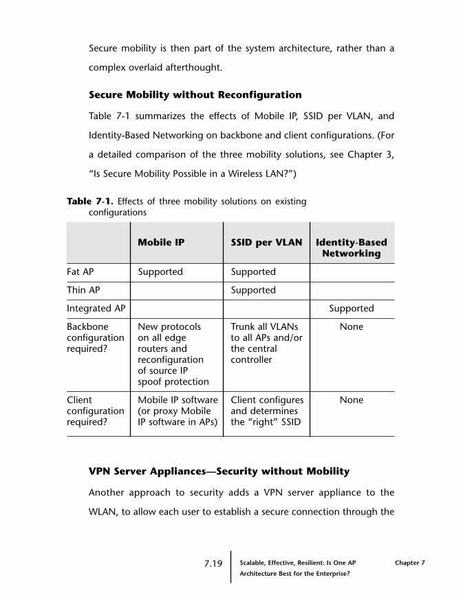
Secure mobility is then part of the system architecture, rather than a
complex overlaid afterthought.
Secure Mobility without Reconfiguration
Table 7-1 summarizes the effects of Mobile IP, SSID per VLAN, and
Identity-Based Networking on backbone and client configurations. (For
a detailed comparison of the three mobility solutions, see Chapter 3,
“Is Secure Mobility Possible in a Wireless LAN?”)
Table 7-1. Effects of three mobility solutions on existingconfigurations
Mobile IP SSID per VLAN Identity-BasedNetworking
Fat AP Supported Supported
Thin AP Supported
Integrated AP Supported
Backbone New protocols Trunk all VLANs Noneconfiguration on all edge to all APs and/orrequired? routers and the central
reconfiguration controllerof source IPspoof protection
Client Mobile IP software Client configures Noneconfiguration (or proxy Mobile and determinesrequired? IP software in APs) the “right” SSID
VPN Server Appliances—Security without Mobility
Another approach to security adds a VPN server appliance to the
WLAN, to allow each user to establish a secure connection through the
7.19 Scalable, Effective, Resilient: Is One AP Chapter 7
Architecture Best for the Enterprise?
WLAN. The VPN server can be embedded in the AP or can operate as a
separate device.
Although the VPN connection secures a user’s connection to a host, it
does not secure the network or the user from outside attacks, nor does
the VPN by itself provide mobility. When VPNs are terminated at an AP
or VPN appliance, users cannot roam from one subnet to another
without ending their sessions or using a tunneling mechanism between
the devices. To resume connection to the network, a roaming user
must log back into the network. Although the VPN connection is
encrypted over the air, the user is still subject to unencrypted access
over the same wireless connection.
Another drawback of using VPN servers as a solution to WLAN security
is the complexity they add to scalability and deployment. Every user
must be configured with the appropriate software and certificates, and
the VPN server must be able to handle all its potential users.
Choosing the Best Architecture for the Enterprise
An integrated AP architecture is built for the enterprise. With it an IT
organization can build a WLAN to meet the demands of thousands of
users. By carefully distributing WLAN functions to where they are most
appropriately performed, this scalable, resilient WLAN can seamlessly
integrate into an existing wired network, with no single point of failure
and no new client software or reconfigurations of the network
backbone.
Chapter 7 Scalable, Effective, Resilient: Is One AP 7.20Architecture Best for the Enterprise?

Table 7-2 summarizes the features of an integrated AP architecture and
compares it to fat and thin AP architectures.
Table 7-2. Comparison of AP architectures
Fat AP Thin AP Integrated AP
Security
Physical No Yes Yessecurity of APs
Security of AP link No No Yes
Identity-Based No No Yesauthorization and enforcement (VLAN membership, ACLs)
Security AP (insecure Central controller Within theenforcement location) (leaves path to wiring closetpoint core vulnerable)
Rogue detection No systemwide Insufficient RF Yeslocation coordination or processing
location horsepower
Management
Speeds network No Yes Yesdeployment
Reduces No Yes Yesmanagement tasks
Planning tools No No Yesfor integrated system deployment
7.21 Scalable, Effective, Resilient: Is One AP Chapter 7
Architecture Best for the Enterprise?

Table 7-2. Comparison of AP architectures—continued
Fat AP Thin AP Integrated AP
Deployment and Scalability
Impact to Mobile IP SSID per VLAN Nonebackbone SSID per VLAN (VLAN to all APs configuration plus the central
controller)
Client Mobile IP software SSID configuration Noneconfiguration (or proxy mobile (the same
IP) and/or SSID 802.1Xconfiguration configuration
as others)
Wiring closet Additional switch Additional switch Mobility switchimpact ports and PoE ports and PoE integrates PoE
required required and networkaccess
PoE External Third-party Integratedthird-party implementationimplementation
Scaling AAA Too many No EAP processing EAP processing,authenticators, no or edge low sessionEAP processing enforcement count, key
generation, distributed AAA load, and edge enforcement
Chapter 7 Scalable, Effective, Resilient: Is One AP 7.22Architecture Best for the Enterprise?

Table 7-2. Comparison of AP architectures—continued
Fat AP Thin AP Integrated AP
Performance
Network Media speed Central controller Media speedperformance limited
CoS and QoS Poor classification; Good classification; Goodgood treatment poor treatment classification
and treatment
Wireless Media speed Central controller Media speedencryption limitedperformance
Key generation Pushed to AAA Pushed to AAA Localized,server server with hardware
assistance
Preserves LAN Per-client tunnels All VLANs central No changetraffic with Mobile IP; all controller; Layer 2 engineering VLANs everywhere path to all APs
with SSID per VLAN
Resilience
Wired Single Ethernet Single Ethernet Dual-homedredundancy Ethernet
PoE Not redundant Not redundant Dual-homedload-shared PoE
Single points PoE, closet switch PoE, closet switch None of failure
AP redundancy Yes (standby AP) Depends on the Yes (plannedvendor coverage/
capacity)
7.23 Scalable, Effective, Resilient: Is One AP Chapter 7
Architecture Best for the Enterprise?

Chapter 7 Scalable, Effective, Resilient: Is One AP 7.24Architecture Best for the Enterprise?

Chapter 8
How Can Wireless LANs BePlanned and Managed?
End users assume that setting up a WLAN is as simple as popping
wireless adapter cards into their laptops and setting up an AP on their
desks. Voila—a WLAN! IT managers know better, but they might have
experience with only small WLANs set up for work groups or
conference rooms. Few IT organizations have built a WLAN with
dozens or hundreds of APs. Designing an enterprise-quality IEEE 802.11
WLAN requires the same disciplined approach that IT managers use for
wired networks.
Architecting WLANs has some unique challenges. Wireless LANs are a
shared media technology like the concentrators and hubs used in shared
Ethernet networks. The absence of dedicated high-speed bandwidth
means WLANs must be engineered to deliver the required capacity
rather than just adequate coverage. WLANs also present a control
challenge. Switched Ethernet links provide a point of control from which
IT staff can manage a user’s impact on the network. Although APs
connect to Ethernet switches, a WLAN cannot provide a fixed control
point, because many users share the connection to an AP. In addition,
because users are mobile and do not remain associated with just one AP,
WLAN architecture has security and management challenges.
8.1 How Can Wireless LANs Be Planned Chapter 8
and Managed?

Network Lifecycle
Building an enterprise WLAN requires a “lifecycle” approach whereby IT
regularly revisits and repeats key network engineering processes to
ensure smooth, ongoing operation. As figure 8-1 shows, these key life
cycle processes include network planning, verification, deployment,
another verification, management, and optimization. After planning the
network, the IT organization must verify the design before deploying it.
Once the WLAN is deployed, IT staff must verify the deployment and
then perform day-to-day monitoring and management tasks. And as
with most network infrastructures, WLAN designs must occasionally be
optimized, returning IT to the planning stage.
Figure 8-1. Building an enterprise WLAN requires a lifecycle approach. Network architects map out a plan,verify the design, and then deploy the WLAN. Oncethe WLAN is in place and physically verified, the ITstaff must have the right tools at their disposal toperform day-to-day management tasks and optimizethe network to accommodate changes. Theoptimization process requires additional planning.
Chapter 8 How Can Wireless LANs Be Planned 8.2and Managed?
TheNetworkLifecycle
Plan
Deploy
VerifyManage
Optimize
Verify

Today’s Planning Method: Trial and Error
Today, most wireless LAN designs rely on trial and error from the very
beginning of the planning stage.
Manual Site Surveys
In a site survey, a systems integrator or IT manager installs an AP and
walks around the office with a wireless-enabled laptop or PDA and site
survey software to take RF signal measurements at various points
throughout the building. Network architects with a couple of WLAN
designs under their belts have logged plenty of miles walking around
facilities to measure RF signal strength and path loss levels.
Even if an IT organization has the patience, time, and attention to
detail required for this tedious process, site surveys typically address
only one facet of building a wireless network—the size of area the RF
signal will cover. In addition, site surveys provide a one-time snapshot
of the RF environment that becomes outdated as soon as the IT
manager walks back to his desk. An IT organization has no way of
knowing about unauthorized wireless APs installed after the site survey
is completed—until IT staff can perform another site survey or wireless
users report performance problems. Today’s site-survey tools do not
consider the network bandwidth or capacity needed for enterprise
business applications, which is a more important design factor for an
enterprise deployment.
8.3 How Can Wireless LANs Be Planned Chapter 8
and Managed?

Site-Survey Tools
To answer the IT organization’s cry for help, many WLAN vendors
bundle basic site survey tools with their APs and network interface
cards. IT organizations planning to design a large number of WLANs
might want to purchase more fully featured site-survey software. Many
site-survey tools for cellular networks also support the 802.11 WLAN
standard. However, these sophisticated software packages are often
costly and geared toward a cellular network designer, not an enterprise
IT manager.
Manual Planning
After the site survey, the planning starts. First IT approximates how
many APs are needed and where to place them, based on the data
gleaned from the site survey, the office floor plan, and the WLAN
product data sheets. Then he or she figures out the correct channel
selections to provide the maximum coverage with a minimum of co-
channel interference. After that, IT fine tunes the quantity and
placement of APs as user feedback about application performance
comes in.
This hit-or-miss approach becomes less effective as the network gets
larger. When a WLAN covers hundreds of users, multiple floors, or very
large areas, back-of-the-envelope calculations can no longer deliver a
well-designed network. For an enterprise deployment, a more
structured and scalable approach is needed.
Chapter 8 How Can Wireless LANs Be Planned 8.4and Managed?
Structured Approach to Planning
The solution is for IT organizations to “plan the air” the way they plan
structured wire networks. When designing a wired enterprise, an IT
organization carefully plans for a connection to each user location,
taking into account the employee’s applications and the bandwidth
required to deliver a productive user experience. IT considers the
resources to be shared among network users, such as servers, printers
and gateways. IT also plans for network access from conference rooms
and other visitor locations.
The same traffic engineering discipline is required for an enterprise
WLAN:
• Can an initial system design that requires a small number of APs
scale to a system with 50 or even 100 APs?
• What is the performance impact of assigning 25 or 50 users to
each AP?
• How much bandwidth do users need from the WLAN?
• How does network performance degrade gracefully with growth?
• At what point does performance begin to degrade?
Designing the RF Plan
With a structured approach, an IT organization can create an RF plan
that includes the following decisions:
• WLAN technology—802.11a offers higher speeds at shorter
ranges, provides more channels, and is more expensive. The
802.11b standard offers lower speeds at greater ranges, provides
fewer channels, and is very cost-effective. The 802.11g standard,
8.5 How Can Wireless LANs Be Planned Chapter 8
and Managed?
when finalized in mid-2003, will offer the same number of channels
as 802.11b, at higher speeds.
• Number of APs required—An enterprise WLAN must be
designed for capacity first, and then for RF coverage. Planning for
capacity usually ensures appropriate coverage.
• Placement of the APs—Locate where the APs and other wireless
equipment will go. Consider mounting the APs on the ceiling and
securing all other equipment in a wiring closet.
• RF attenuation factors—Walls, windows, and elevators absorb
signals and must be considered in cell coverage calculations.
• Cell size—Use of smaller cells, or microcells, increases WLAN
throughput.
• Channel selection—Proper channel selection can minimize
co-channel interference with adjacent cells.
• Minimum user association rates—The data rate at which each
user associates with an AP affects the bandwidth of all users in the
coverage area.
• Margin for growth—Planning for growth at the start, designing
for greater usage than the initial deployment requires, can mitigate
the need for future adjustments.
Select a WLAN Technology
First, the network designer must select the 802.11 technology to use in
the WLAN.
802.11a
Products based on 802.11a technology will rapidly come to market in
2003, making them more affordable and widely available. Operating in
the 5 GHz band, 802.11a WLANs support a maximum theoretical data
Chapter 8 How Can Wireless LANs Be Planned 8.6and Managed?

rate of 54 Mbps, but after overhead deliver throughput somewhere
between 20 Mbps and 25 Mbps in normal traffic conditions. In a
typical office environment, the maximum signal range is 50 meters
(150 feet) at the lowest speed, but at higher speeds, the range is less
than 23 meters (75 feet). Transmission via 802.11a takes place on four,
eight, or more channels, depending on the country.
802.11b
Most WLANs deployed today use 802.11b technology. It operates in the
2.4 GHz band, uses three non-overlapping channels, and supports a
maximum theoretical data rate of 11 Mbps, with throughput averaging
in the 4 Mbps to 6 Mbps range. In a typical office environment, the
maximum signal range is 75 meters (250 feet) at the lowest speed, but
at higher speeds the range is about 30 meters (100 feet). Bluetooth
devices, 2.4 GHz cordless telephones, and even microwave ovens are
sources of interference and impact performance of 802.11b networks.
Products based on 802.11b have been shipping in quantity for several
years. Pricing is affordable and suppliers are plentiful.
802.11g
The 802.11 task force is still developing the 802.11g standard, which is
based on 802.11b and is likely to be ratified sometime in 2003.
Offering the throughput of 802.11a and backward compatibility to
802.11b, 802.11g operates in the 2.4 GHz band and delivers data rates
from 6 Mbps to 54 Mbps. Like 802.11b, 802.11g has up to three non-
overlapping channels. Because 802.11g is backward-compatible to
8.7 How Can Wireless LANs Be Planned Chapter 8
and Managed?
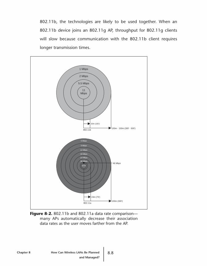
802.11b, the technologies are likely to be used together. When an
802.11b device joins an 802.11g AP, throughput for 802.11g clients
will slow because communication with the 802.11b client requires
longer transmission times.
Figure 8-2. 802.11b and 802.11a data rate comparison—many APs automatically decrease their associationdata rates as the user moves farther from the AP.
Chapter 8 How Can Wireless LANs Be Planned 8.8and Managed?
23m (75')
100m (300')
48 Mbps
6 Mbps
9 Mbps
12 Mbps
18 Mbps
24 Mbps
36 Mbps
54 M
30m (100')
100m - 150m (300' - 500')
1 Mbps
2 Mbps
5.5 Mbps
11Mbps
802.11b
802.11a

Plan for Capacity—Coverage Will Follow
A fundamental requirement for designing enterprise WLANs is planning
for capacity, rather than focusing on RF coverage, as designers of early
WLANs did. User devices in a successful enterprise deployment must
not only be able to detect the RF signal, they must also have adequate
bandwidth to run applications effectively. Planning for capacity almost
always guarantees the necessary coverage.
To determine capacity requirements, an IT manager must know how
many users will connect in a particular coverage area, what
applications they are running, and how much bandwidth they need.
(For an in-depth discussion of planning for capacity over coverage, see
Chapter 5, “Capacity vs. Coverage: Can This Complex Design Problem
Be Solved?”)
Based on the capacity requirements, the user count, and the coverage
areas, the IT manager can calculate how many APs need to be
deployed. The greater the capacity and users, the higher the number of
APs needed. A large WLAN might require hundreds of APs to deliver
throughput sufficient for enterprise applications.
Place the APs in the Floor Plan
The next step is to place the APs, central controllers, and other WLAN
components in the planning tool’s floor plan. In work group WLANs,
APs are often placed on desktops. But in enterprise deployments, APs
are typically mounted on the ceiling. In addition to having fewer
obstacles to interrupt the signal, ceiling-mounted APs stay above the
8.9 How Can Wireless LANs Be Planned Chapter 8
and Managed?

office fray, minimizing the possibility of tampering. Central controllers
must be secured in a locked wiring closet or data center located close
to the coverage area.
Consider the RF Attenuation Factors
WLAN planning must account for how physical objects reduce the
distance that an RF signal reaches. Structural elements such as doors,
windows, cubicles, elevators, and walls absorb and attenuate RF
signals. Sophisticated equations aid in calculating RF loss factors, but
common sense prevails, too. For instance, concrete walls absorb more
signal than glass windows and cause greater RF attenuation.
Determine the Cell Size and Select Channels
Cell size, a concept specific to WLANs, is the area within which the RF
signal from a given AP can be received. APs with the highest radio
power cover the broadest area. IT managers designing only for
coverage often maximize the radio power to lengthen the signal’s
reach. But designing only for coverage can deprive users of an
acceptable WLAN experience. To design for better capacity, IT
managers need to create microcells with APs.
Creating Microcells to Increase Capacity
Microcells are areas of RF coverage that are smaller than the AP’s full
power can achieve. They boost overall network throughput by sharing
more bandwidth among fewer users. Instead of operating an 802.11a
AP at its maximum power and achieving a cell radius of 50 meters (150
feet), IT staff might create cells with a radius of 25 meters (75 feet)
Chapter 8 How Can Wireless LANs Be Planned 8.10and Managed?

using a lower AP power setting. With 802.11b, a radius of 30 meters
(100 feet) might be preferable to a radius of 75 meters (250 feet).
Assigning Channels to Prevent Interference
As IT deploys more APs in a given physical part of the building by
shrinking the cell size, they must carefully vary channel assignments to
prevent co-channel interference. Signals from adjacent APs using the
same channel will interfere with each other, degrading WLAN
performance. The 802.11a technology offers at least eight non-
overlapping channels, while 802.11b and 802.11g have only three.
Although microcells deliver greater network capacity, they require a
greater number of channels than networks that are designed only for
coverage. As the number of APs increases, channel assignment
becomes complex. IT needs tools for channel assignment that
minimize co-channel interference.
Adjusting Power Carefully
IT must take care in adjusting the radio power of an AP. Power levels
that are too high create co-channel interference, and levels that are too
low leave coverage gaps.
Not all APs support power adjustments. To gain the needed design
control, IT managers must choose a vendor who offers this feature in
software. Adjusting the power levels is not intuitive. For example,
changing the power from 100 milliwatts to 50 milliwatts does not
necessarily cut the range in half. After adjusting power levels, managers
require tools that help them verify the resulting coverage area.
8.11 How Can Wireless LANs Be Planned Chapter 8
and Managed?

Specify Minimum User Association Rates
To achieve good network throughput also requires that managers
control the data rate clients are allowed to use when communicating
with an AP. To maximize the bandwidth capacity of a particular AP’s
cell, IT must make sure that all clients associating with the AP are
running at maximum rates—either 11 Mbps for 802.11b or greater
than 36 Mbps for 802.11a. Even one user communicating at a lower
speed affects the throughput of everyone else, because the slower user
takes up more air time for packet transmissions.
Allow a Growth Margin
A good design also incorporates a margin for growth and increased
usage. Adding a growth factor to the user count, bandwidth, and
coverage area makes the design useful for a longer period of time. For
example, to allow for new and roaming users IT might design a
coverage area intended for 50 users for 60 users instead.
Verifying, Deploying, and Verifying Again—with Tools
The next requirements in the WLAN life cycle are to verify the design,
deploy the APs, and verify the deployment. The greater the capacity
required by the users’ applications and office environment, the
greater the number of APs required. Because an enterprise WLAN
might need dozens to hundreds of APs, having automated software-
based deployment tools can dramatically simplify configuration
and management.
Chapter 8 How Can Wireless LANs Be Planned 8.12and Managed?
Tools for Verifying Plans and Pushing Configurations
How does IT verify that the WLAN design will work as expected? Site
surveys provide only a snapshot of the environment at a single instance
in time. Networks and offices are in a constant state of flux—users
connect and disconnect in random patterns; new applications are
deployed; cubicles and walls are constantly being built, moved, or torn
down; people and equipment coming in and out of the area change
the RF environment and affect the WLAN.
To reduce the cost and complexity associated with manual WLAN
deployments, enterprise-class planning tools can automatically convert
design plans into configuration data for APs and other system
elements. These tools allow the IT staff to stage and deploy the system
by pushing the configuration information out to all APs automatically.
In an enterprise-scale deployment, configuring each AP individually
is impractical.
Tools for Verifying the Network
Today, the network verification process consists of measuring user
complaints. Users inform the help desk that they have no network
access or that an application is unbearably slow. This approach to
verification cannot serve enterprise requirements. IT managers require
tools that simulate the WLAN environment and automate verification
tasks. The best WLAN vendors will provide tools that do the following:
• Automatically identify conflicts in channel assignments and make
recommended fixes—saving the IT manager hours of manual
adjustments in the process.
8.13 How Can Wireless LANs Be Planned Chapter 8
and Managed?
• Simulate the RF topology for the user count to verify that sufficient
bandwidth is available.
• Check service levels for each coverage area based on
predetermined throughput and capacity parameters.
• Verify the configurations of APs that support load-sharing to improve
performance and fault tolerance.
• Let managers double-check the planned design after they physically
deploy the network.
Managing the WLAN—with Tools
A web-based management application embedded in an AP might be fine
for a 20-user deployment, but AP-by-AP management isn’t appropriate
for a 200-user or 2000-user WLAN. Nor should a WLAN management
application break the IT budget. Today’s WLAN management software
lacks crucial capabilities for enterprise deployments.
WLAN management software can let IT staff know who is on the
network and where the users are located. It can help IT managers set
policies for users and groups of users to control what they access, what
type of encryption and authorization they have, how much bandwidth
they can consume, and where they can roam.
Management software can assist IT staff in configuring and managing
APs, and monitoring operational statistics and events. Although AP
configuration can be a one-time event, WLAN technologies are rapidly
evolving in every area from RF to access control to security. As a result,
firmware and software updates are a foregone conclusion. A useful
WLAN system supports AP software and firmware updates from a central
Chapter 8 How Can Wireless LANs Be Planned 8.14and Managed?

repository. Requiring an IT manager to update the configuration of each
individual AP via telnet or a web browser is impractical.
Detecting rogue APs, rogue users, and ad hoc user groups is an
ongoing requirement for intrusion detection, but today’s WLAN
management tools overlook this critical feature. Management software
can detect and locate these unauthorized elements. Knowing that an
unauthorized user is on the premise is useless without knowing his or
her location.
Obtaining concise and meaningful statistics about network
performance is critical to WLAN management. Reams of SNMP alerts
and statistics are not useful, because they provide no correlation to
help managers resolve problems. Statistics must be collected and
correlated on a system-wide basis for intelligent analysis by the IT
manager. Correlation of performance data alerts IT organizations to
trends such as peak usage at specific time periods by roaming users.
The trends might require tweaks to the network design for consistent
service during peak intervals.
Optimizing the WLAN—with Tools
Optimization tools let IT modify the RF plan based on actual
performance. For example, if users are moving around more than
anticipated, each AP must support more users. Or maybe application
performance is too slow. Management tools can indicate areas of
congestion in a hotspot area such as a conference room. Factoring in
some margin for growth at the beginning of the design helps delay
8.15 How Can Wireless LANs Be Planned Chapter 8
and Managed?
such optimization requirements, but ultimately IT needs optimization
tools that incorporate feedback, from users and from the system, for
different areas.
With the right set of optimization tools, IT can model changes to the
network. For example, IT might have designed for 1 Mbps of
bandwidth per user in an area where 2 Mbps is now required.
Optimization tools for the WLAN system can run the calculations and
recommend ways in which the network can be modified to meet new
requirements. Tools can also accommodate network additions, moves,
and changes—by automating all the configurations for new APs and
the changes to existing APs as it did for the initial deployment.
Today, because few WLAN vendors offer optimization tools, IT
must use time-consuming trial-and-error methods. Comprehensive
optimization tools need to be an essential part of an enterprise
WLAN system.
Effective Management Tools Make the Difference
As WLANs in the enterprise proliferate, IT must apply the same
structured and scalable approach to planning and design as they do to
the wired infrastructure. A trial-and-error design approach is ineffective
when dozens or hundreds of APs are needed. As a vital part of the
overall network framework, WLANs must be given proper consideration
in the network life cycle. Having the right set of tools for planning,
verifying, deploying, managing, and optimizing WLANs is paramount
to ensure a successful and scalable WLAN deployment.
Chapter 8 How Can Wireless LANs Be Planned 8.16and Managed?
Most tools that are available for WLANs today lack the system
capabilities necessary to sustain enterprise-class performance
throughout the network. Fortunately, higher-functioning system tools
will come to market in 2003 to help network architects plan and deliver
enterprise-grade WLANs wherever they are needed.
8.17 How Can Wireless LANs Be Planned Chapter 8
and Managed?

Chapter 8 How Can Wireless LANs Be Planned 8.18and Managed?

Chapter 9
Designing a WLAN MobilitySystem
There are a wide range of design scenarios that affect the planning,
deployment and management of WLAN infrastructures. Whether the
point of integration for wireless is in the data center, in wiring closets,
throughout an enterprise campus or limited to specific areas, unique
design considerations must be given to each practical application.
Integrating WLANs into the Data Center
To implement IEEE 802.1X user authentication on a WLAN, IT must
properly integrate the WLAN with the AAA server. Typically this is a
RADIUS server. This is done by ensuring that existing active directory
policies and workgroup assignments are consistent with existing VLAN
assignments configured for the network. During the active directory
integration, define and implement separate policies for wireless
workgroups using PEAP-MS-CHAP v2 and EAP-TLS to utilize digital
certificates for authenticating users in the wireless network.
After authenticating and authorizing a user, the RADIUS server stores
the usage records and other accounting information to a database for
reference during troubleshooting or for billing.
9.1 Designing a WLAN Mobility System Chapter 9

Consideration
When a large number of users simultaneously authenticate on a single
RADIUS server, there’s a significant impact on the performance of that
server. In the design of the WLAN it is imperative to account for the
peak number of clients that will be authenticated simultaneously,
rather than the total number of clients that will login to the network.
Below are the minimum performance and capacity requirements
Microsoft recommends for its IAS RADIUS Server:
Server requirement:
• Minimum: 1.8 GHz Pentium 4 processor
Client environment:
• Clients authenticate every 20 minutes
RADIUS processing performance and criteria:
• Password authentication - typical server handles approximately
100 PEAP-MSCHAPv2 transactions per second
• Certificate authentication with public key operation for first
authorization followed by a quick reauthorization for eight hours
by default. Typical server handles approximately 100 TLS and/or
PEAP-TLS transactions per second.
Recommendation
A minimum of two RADIUS servers are recommended in an enterprise
network to ensure support of all 802.1X users and for redundancy in
case of a primary server failure. Additionally, when two RADIUS servers
are configured for load balancing or round robin in the network, any
number of users simultaneously authenticating on the RADIUS server
will be load balanced between the two servers.
Chapter 9 Designing a WLAN Mobility System 9.2
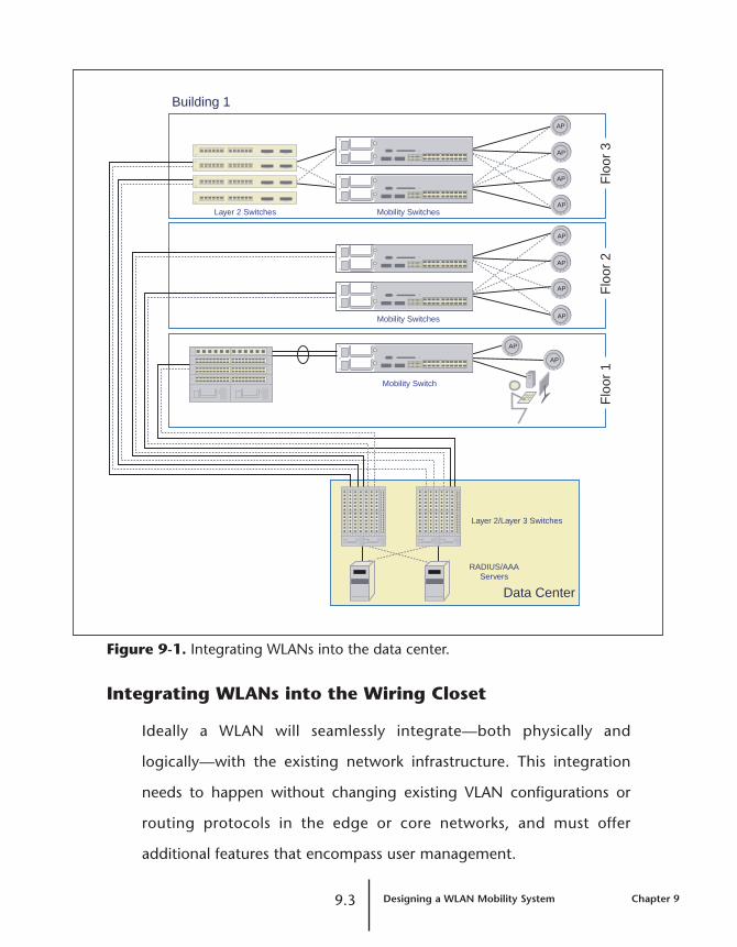
Figure 9-1. Integrating WLANs into the data center.
Integrating WLANs into the Wiring Closet
Ideally a WLAN will seamlessly integrate—both physically and
logically—with the existing network infrastructure. This integration
needs to happen without changing existing VLAN configurations or
routing protocols in the edge or core networks, and must offer
additional features that encompass user management.
9.3 Designing a WLAN Mobility System Chapter 9
Layer 2 Switches Mobility Switches
Building 1
Data CenterF
loor
3F
loor
2
Layer 2/Layer 3 Switches
RADIUS/AAAServers
Mobility Switch
Flo
or 1
Mobility Switches
AP
AP
AP
AP
AP
AP
AP
AP
AP
AP
Begin with determining the number and location of the mobility
switches and APs for a given floor of a building. A robust planning tool
can provide a work order showing the wiring closet and corresponding
mobility switches plus the list of APs to be installed throughout the
building. Without this type of planning tool, the network manager will
need a hand-held RF device and a lot of spare time for the trial-and-
error approach of placing APs for capacity and coverage.
Physical connectivity between the existing wiring closet Layer 2
switches and the mobility switch will use either Fast Ethernet or Gigabit
Ethernet uplinks. Use dual-homed links to connect to two different
switches for redundancy. For load-shared redundancy with VLANs, use
PVST+ to load share traffic from multiple VLANs over the active,
redundant links.
Physical connectivity between the mobility switch and AP will require
new cable to be pulled for both network connectivity and PoE to the AP
locations. If the APs are plenum rated they may mount either directly
on or behind the ceiling tiles. For redundancy, use APs that support
dual-homed links to two different mobility switches.
Next, determine user-based identity for VLAN assignments utilizing the
RADIUS server, as described in the previous data center section.
The WLAN in the following diagram, Figure 9-2, enables VLANs in the
air through the APs and mobility switches. When a wireless user first
logs in to the network, an association with the WLAN occurs through
the AP using 802.11a or 802.11b technology. The APs are directly
Chapter 9 Designing a WLAN Mobility System 9.4

connected to the mobility switch via dual redundant Fast Ethernet
links. The mobility switch is connected to the Layer 2/Layer 3 core
switch via 802.1Q, either directly using dual redundant Gigabit
Ethernet links, or via Layer 2 switches in the wiring closet. The
RADIUS AAA server propagates the user’s VLAN membership to the
mobility switches.
Figure 9-2. Integrating WLANs into the wiring closet.
9.5 Designing a WLAN Mobility System Chapter 9
Layer 2 Switches Mobility Switches
Building 1
Data Center
Flo
or 3
Flo
or 2
Layer 2/Layer 3 Switches
RADIUS/AAAServers
Mobility Switch
Wiring Closet
Wiring Closet
Wiring Closet
Flo
or 1
Mobility Switches
AP
AP
AP
AP
AP
AP
AP
AP
AP
AP

Recommendation
Make sure that the newly installed mobility switch and the existing
Layer 2 distribution switch in the wiring closet utilize the same trunking
protocol, such as 802.1Q. Additionally configure the mobility switch
with the same VLAN names as the Layer 2 switch to which they
directly connect. This will ensure that VLAN traffic travels consistently
and without interruption between the distribution switch and the
mobility switch.
Integrating WLANs throughout the Campus
Repeat the steps above for all remaining floors and buildings of the
campus. A robust planning tool can help avoid co-channel interference
between floors of a building.
Consideration
User roaming may be categorized into one of the following scenarios
when implementing secure mobility. The first scenario is a user
roaming between APs that are directly connected to the same mobility
switch. Since the roaming user’s VLAN is already on the same mobility
switch, the switch doesn’t have to perform a RADIUS look up and no
Layer 2 tunnel is formed.
The second scenario is a user roaming between two sets of mobility
switches and APs, with each mobility switch and AP pair containing the
user’s assigned VLAN. In this scenario no Layer 2 tunnel is necessary for
the user to have access to the assigned VLAN.
Chapter 9 Designing a WLAN Mobility System 9.6
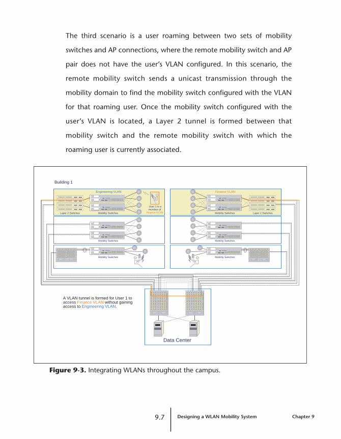
The third scenario is a user roaming between two sets of mobility
switches and AP connections, where the remote mobility switch and AP
pair does not have the user’s VLAN configured. In this scenario, the
remote mobility switch sends a unicast transmission through the
mobility domain to find the mobility switch configured with the VLAN
for that roaming user. Once the mobility switch configured with the
user’s VLAN is located, a Layer 2 tunnel is formed between that
mobility switch and the remote mobility switch with which the
roaming user is currently associated.
Figure 9-3. Integrating WLANs throughout the campus.
9.7 Designing a WLAN Mobility System Chapter 9
Building 1
A VLAN tunnel is formed for User 1 toaccess Finance VLAN without gainingaccess to Engineering VLAN.
Layer 2 Switches Mobility Switches
Data Center
Engineering VLAN
Mobility Switches
User 1 is amember of
Finance VLAN Layer 2 SwitchesMobility Switches
Finance VLAN
Mobility Switches
Mobility Switches
Mobility Switches
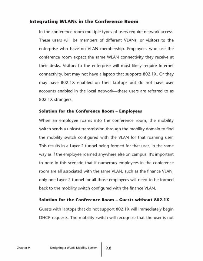
Integrating WLANs in the Conference Room
In the conference room multiple types of users require network access.
These users will be members of different VLANs, or visitors to the
enterprise who have no VLAN membership. Employees who use the
conference room expect the same WLAN connectivity they receive at
their desks. Visitors to the enterprise will most likely require Internet
connectivity, but may not have a laptop that supports 802.1X. Or they
may have 802.1X enabled on their laptops but do not have user
accounts enabled in the local network—these users are referred to as
802.1X strangers.
Solution for the Conference Room – Employees
When an employee roams into the conference room, the mobility
switch sends a unicast transmission through the mobility domain to find
the mobility switch configured with the VLAN for that roaming user.
This results in a Layer 2 tunnel being formed for that user, in the same
way as if the employee roamed anywhere else on campus. It’s important
to note in this scenario that if numerous employees in the conference
room are all associated with the same VLAN, such as the finance VLAN,
only one Layer 2 tunnel for all those employees will need to be formed
back to the mobility switch configured with the finance VLAN.
Solution for the Conference Room – Guests without 802.1X
Guests with laptops that do not support 802.1X will immediately begin
DHCP requests. The mobility switch will recognize that the user is not
Chapter 9 Designing a WLAN Mobility System 9.8
802.1X-enabled and will place that visitor on a guest VLAN, without
pushing that request back to the AAA server.
Figure 9-4. An unknown user in the conference room isimmediately placed on the appropriate guest VLAN.
Solution for the Conference Room – 802.1X Strangers
One type of 802.1X stranger is the recognized repeat-visitor who has
special requirements for QoS—for example, the vice president of sales
for the enterprise’s most strategic reseller partner, or members of the
board of directors. Their requirements will not be met if this recognized
visitor is placed on the same VLAN as an unknown guest. In order to
deliver appropriate services to this visitor, the MAC address of this
visitor’s laptop is stored on the back-end AAA server. Upon login the
9.9 Designing a WLAN Mobility System Chapter 9
Wiring Closet Conference Room
VLAN 1 = Guest VLANVLAN 2 = Guest-with-Privileges VLAN
Mobility Switches
User 2 is an unrecognized guest and does not have 802.1X enabled on its laptop. The mobility switchplaces him on the appropriate Guest VLAN.
Data Center
AP
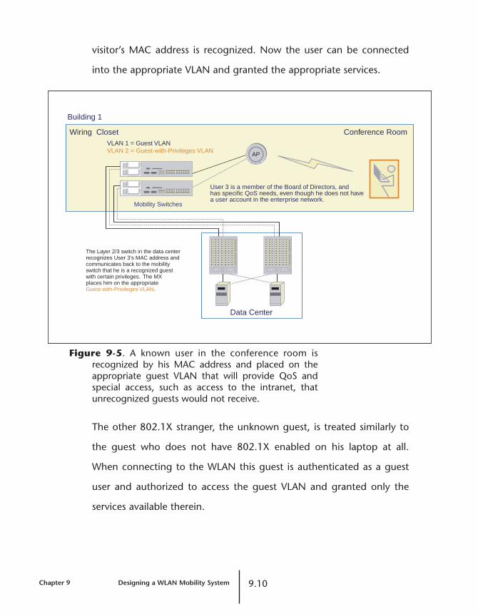
visitor’s MAC address is recognized. Now the user can be connected
into the appropriate VLAN and granted the appropriate services.
Figure 9-5. A known user in the conference room isrecognized by his MAC address and placed on theappropriate guest VLAN that will provide QoS andspecial access, such as access to the intranet, thatunrecognized guests would not receive.
The other 802.1X stranger, the unknown guest, is treated similarly to
the guest who does not have 802.1X enabled on his laptop at all.
When connecting to the WLAN this guest is authenticated as a guest
user and authorized to access the guest VLAN and granted only the
services available therein.
Chapter 9 Designing a WLAN Mobility System 9.10
Building 1
The Layer 2/3 switch in the data centerrecognizes User 3's MAC address andcommunicates back to the mobilityswitch that he is a recognized guestwith certain privileges. The MX places him on the appropriateGuest-with-Privileges VLAN.
Wiring Closet Conference RoomVLAN 1 = Guest VLANVLAN 2 = Guest-with-Privileges VLAN
Mobility Switches
User 3 is a member of the Board of Directors, andhas specific QoS needs, even though he does not havea user account in the enterprise network.
Data Center
AP
ReferencesJ. Andersen, T. Rappaport, and S. Yoshida
“Propagation Measurements and Models for Wireless Communications
Channels,” IEEE Communications Magazine, pp. 42-49, January 1995.
S. Arnesen and K. Haland
“Modeling of Coverage in WLAN,” PhD Thesis, Agder University,
2001.
J. Chen and J. Gilbert
“Measured Performance of 5-GHz 802.11a Wireless LAN Systems,”
Atheros white paper, 2001.
K. Dulaney and M. Margevicius
“Wireless LANs for Notebooks Begin to Make Sense,” Gartner’s
End-User Computing Research Note TG-17-3810, August 1, 2002.
V. Erceg, et al
“Channel Models for Fixed Wireless Applications,” IEEE 802.16a
standards document, July 2001,
http://ieee802.org/16/tg3/contrib/802163c-01_29r4.pdf.
V. Erceg, et al
“An Empirically Based Path Loss Model for Wireless Channels in
Suburban Environments,” IEEE Journal on Selected Areas in
Communications, pp. 1205-1211, July 1999.
10.1 References

M. Margevicius, J. Girard and M. Reynolds
“Finding ‘Rogue’ WLAN Access Points,” Gartner Research document
TG-17-2804, August 8, 2002.
J. Medbo, et al
“Measured Radiowave Propagation Characteristics at 5 GHz for
typical HIPERLAN/2 Scenarios,” ETSI EP BRAN document 3ERI084A,
March 1998.
NIST AES FAQ: http://csrc.nist.gov/CryptoToolkit/aes/aesfact.html
J. Yee and H. Pezeskhi-Esfahani
“Understanding Wireless LAN Performance Tradeoffs,”
Communication Systems Design, November 1, 2002,
http://www.commsdesign.com/story/OEG20021101S0015.
References 10.2

Appendix
Request for Proposal (RFP)Example
The bottom line for the implementation of a WLAN in the enterprise is
right here—the RFP. Any enterprise looking to deploy a wireless LAN
must define the set of requirements needed to select, install, and
manage a scalable, truly enterprise-class mobility system. The technical
requirements outlined below are designed to raise the bar on the
functional capabilities needed to meet these enterprise demands. The
sample data included here is confined to the technical requirements
section of an RFP. Enterprises would likely also include sections
requesting information about warranty, support, and maintenance
contracts, outlining their existing infrastructure with which the vendor
would have to integrate, and defining the goals, objectives and
timelines of the project.
Wireless LAN RFP: Technical Requirements
1. Architecture Overview and System Technology
1.1. Provide a brief overview of the wireless system architecture
and elements (i.e., is it an integrated system with a
centralized intelligent device or is it a collection of fat APs?).
1.2. Please describe any aspects of the architecture that help
scale the following:
1.2.1. Throughput
1.2.2. User and system control
11.1 Request for Proposal (RFP) Example Appendix

1.2.3. Management
1.3. For systems with a centralized intelligent device:
1.3.1. What functions are performed by the intelligent
device?
1.3.2. What functions are performed by the APs?
1.3.3. The centralized device should not limit the available
WLAN bandwidth. What is the data throughput of
the device? Please specify packets per second and
bits per second.
1.3.4. Where do the intelligent devices reside in the
network?
1.3.5. Does the device actively monitor and forward data
to and from the APs?
1.3.6. How do the intelligent devices attach to the network?
1.3.7. What media type and speeds are supported for
network connectivity of the intelligent device?
1.3.8. What redundancy and load-sharing capabilities are
supported on the network links of the intelligent
device (note that additional redundancy questions
follow in a later section)?
1.3.9. Do the intelligent devices communicate with each
other? How? For what purpose?
1.3.10. How do the intelligent devices physically link to the
APs/radios?
1.3.11. How do the intelligent devices communicate with
the APs?
1.3.12. Do the intelligent devices support wired users as
well as APs? What functions are supported for the
wired users?
Appendix Request for Proposal (RFP) Example 11.2

1.4. Describe the supported AP types and radios.
1.4.1. There is a desire to support both .11b and .11a or
to migrate between .11b and .11a. Is there an AP
type that supports this capability? Can the AP run
both radio types simultaneously and pass line-rate
traffic at their highest associate rate (54 Mbps and
11 Mbps respectively)?
1.4.2. Is there an AP type that is software-configurable to
run 802.11a or 802.11b?
1.4.3. What are the Power over Ethernet (PoE) restrictions
for the various AP types?
1.4.4. What is the AP’s Power over Ethernet (PoE) source?
1.4.5. What kind of antennas do the APs support?
1.4.6. Are the power settings tunable? If so, how? To what
level of granularity?
1.4.7. There is concern over the management, scalability
and deployment costs for a systemwide deployment
of APs.
1.4.7.1. Describe the management and
configuration model for the AP. Are
configuration elements stored on the AP?
How are firmware upgrades across dozens
or hundreds of APs handled? How are
unique configuration changes across
dozens or hundreds of APs handled?
1.4.7.2. Does the AP have a console port?
1.4.7.3. Does the AP utilize an IP address?
1.5. Describe system software functionality (detailed questions
follow later).
11.3 Request for Proposal (RFP) Example Appendix

1.6. Provide an overview of the management capabilities
(detailed questions follow later).
1.7. Describe the suitability of this architecture for supporting
voice over 802.11.
1.8. Describe what client software is supported.
2. Planning and Design
A significant concern is how the wireless LAN will be planned and
designed, incorporating both current coverage and capacity needs
but also future expectations. The questions below are focused on
understanding the planning process for the proposed system.
2.1. To what extent are site surveys required both now and
when a floor plan or office layout is changed?
2.2. Does the system allow the integration of CAD drawings for
floor plans (e.g. DXF, DWG file formats) to spatially
determine the number and placement of APs?
2.3. How do the planning process and tools determine the
number and placement of APs to deploy? Describe how
bandwidth requirements are incorporated into this design.
Please highlight where processes are automated.
2.4. Describe how “what-if” scenario planning is handled for
designs incorporating more or less bandwidth capacity,
various radio technologies, and differences in office layout
or other potential RF obstructions?
2.5. How does the planning tool support subsequent moves,
adds, and changes within the WLAN or the environment
(floor plan, office layout) that it serves?
2.6. Is this software internally developed, OEMed, or acquired
by the end user from a third party?
Appendix Request for Proposal (RFP) Example 11.4
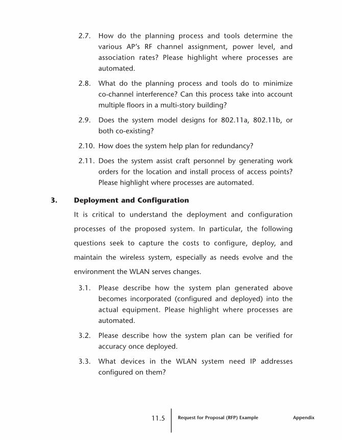
2.7. How do the planning process and tools determine the
various AP’s RF channel assignment, power level, and
association rates? Please highlight where processes are
automated.
2.8. What do the planning process and tools do to minimize
co-channel interference? Can this process take into account
multiple floors in a multi-story building?
2.9. Does the system model designs for 802.11a, 802.11b, or
both co-existing?
2.10. How does the system help plan for redundancy?
2.11. Does the system assist craft personnel by generating work
orders for the location and install process of access points?
Please highlight where processes are automated.
3. Deployment and Configuration
It is critical to understand the deployment and configuration
processes of the proposed system. In particular, the following
questions seek to capture the costs to configure, deploy, and
maintain the wireless system, especially as needs evolve and the
environment the WLAN serves changes.
3.1. Please describe how the system plan generated above
becomes incorporated (configured and deployed) into the
actual equipment. Please highlight where processes are
automated.
3.2. Please describe how the system plan can be verified for
accuracy once deployed.
3.3. What devices in the WLAN system need IP addresses
configured on them?
11.5 Request for Proposal (RFP) Example Appendix

3.4. What impact is there, if any, on client IP addressing and
address consumption in a DHCP environment? Please
specify the IP address architecture requirements for the
overall system.
3.5. If an intelligent device is used, please describe the
configuration. Is any part of the process automated?
3.6. Please describe the configuration of the APs. Is any part of
the process automated?
3.7. If it is determined that an existing deployment requires an
additional AP to improve coverage or capacity in an area
already surrounded by APs, please describe the process to
configure/re-configure all the affected APs.
3.8. Does client software need to be configured? Please detail.
3.9. Does client software need to be installed to support the
WLAN system? Is this software proprietary?
3.10. Are there configuration changes needed on the network
backbone to support the WLAN devices? Please detail.
3.11. Are there configuration changes needed on aggregation or
edge switches and routers? Please detail.
4. VLAN Support
A significant concern is the preservation of existing network
engineering in the form of VLANs already deployed on the wired
network. The questions below are focused on understanding the
VLAN implementation of the proposed system.
4.1. Please define the VLAN topology requirements and
restrictions for the wireless system.
4.2. How does the system support multiple VLANs in the air?
Appendix Request for Proposal (RFP) Example 11.6

4.3. Do any switch or router ports need to be changed to
support VLANs in the air?
4.4. Does every VLAN have to be accessible on every subnet
supporting the WLAN?
4.5. How does the system support guest access while still
securing employee traffic?
4.6. How does the VLAN implementation map to pre-existing
VLANs on the wired network?
4.7. Does the VLAN implementation maintain and invoke
network engineering already in the wired network (i.e., are
wireless traffic flows routed through the same infrastructure
as they would be on the wired network)?
4.8. Is VLAN membership explicitly controlled by the system or
can users select their VLAN (i.e. by choosing which SSID to
use)? What specific 802.11 client capabilities are required
to enable client VLAN selection, if supported?
5. Security – AAA, Encryption, Traffic Isolation
A significant concern is the breadth of security measures supported
by the proposed WLAN system. The following questions are
designed to determine standards adherence, range of security
protocols supported, and future-proofing of the system.
5.1. What methods of authentication are supported?
5.2. What EAP protocols are supported?
5.3. What client software configuration is needed to work with
these EAP protocols?
5.4. Which of the system devices act as the AAA authenticator?
11.7 Request for Proposal (RFP) Example Appendix
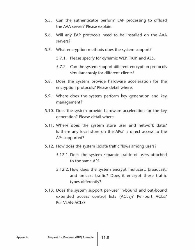
5.5. Can the authenticator perform EAP processing to offload
the AAA server? Please explain.
5.6. Will any EAP protocols need to be installed on the AAA
servers?
5.7. What encryption methods does the system support?
5.7.1. Please specify for dynamic WEP, TKIP, and AES.
5.7.2. Can the system support different encryption protocols
simultaneously for different clients?
5.8. Does the system provide hardware acceleration for the
encryption protocols? Please detail where.
5.9. Where does the system perform key generation and key
management?
5.10. Does the system provide hardware acceleration for the key
generation? Please detail where.
5.11. Where does the system store user and network data?
Is there any local store on the APs? Is direct access to the
APs supported?
5.12. How does the system isolate traffic flows among users?
5.12.1. Does the system separate traffic of users attached
to the same AP?
5.12.2. How does the system encrypt multicast, broadcast,
and unicast traffic? Does it encrypt these traffic
types differently?
5.13. Does the system support per-user in-bound and out-bound
extended access control lists (ACLs)? Per-port ACLs?
Per-VLAN ACLs?
Appendix Request for Proposal (RFP) Example 11.8

6. Rogue Detection
A primary goal of the WLAN deployment is to use the system as a
mechanism for detecting and locating rogue APs and users. The
following questions are aimed at understand how the proposed
system aids in this critical function.
6.1. How does the system identify, report, and locate rogue APs,
rogue users, and ad hoc networks?
6.2. Does the system need separate devices for rogue detection,
or does it use the system’s APs for this function?
6.3. Does the system perform rogue detection automatically?
Please detail.
6.4. Does the system listen for all RF activity or only beacons?
6.5. Can the system support timed intervals for sweeping a
facility or collection of facilities?
6.6. Does the system send alerts when rogues are detected?
7. Roaming
A primary goal for a WLAN is to support roaming. It is critical that
roaming not complicate deployment or troubleshooting, compromise
security, or necessitate multiple client logins and authentications.
The following questions are designed to explain how the system
supports roaming.
7.1. How does the system support roaming between APs or
between intelligent devices when the APs or intelligent
devices reside on different subnets?
7.2. Can users maintain the same IP address as they roam?
11.9 Request for Proposal (RFP) Example Appendix
7.3. As a user roams, does he need to re-authenticate or
re-login?
7.4. Does the user’s subnet attributes (VLAN, ACLs, route
policies) follow the user as he roams?
7.5. Does the system support any mechanisms to control where
users can physically roam throughout the WLAN
infrastructure?
7.6. Does roaming require changes to the network switches
or routers?
7.7. Does roaming require installation of new client software?
7.8. Does roaming require changes to existing client software?
7.9. Does roaming support only IP user traffic or other protocols?
Please specify how.
7.10. Is traffic switched locally among users roaming on the same
subnet, or is traffic always tunneled in some fashion?
8. System Capacity and Performance
A major concern is that the WLAN provide sufficient capacity for
business-level application performance. The following questions will
help in determining how the system helps IT design for performance
vs. simple RF signal reach.
8.1. Does the system help the IT staff design for overall capacity
rather than just coverage? Can it let IT set average
bandwidth requirements per user?
8.2. Does the system support setup and enforcement of
minimum association rates to improve system performance?
Please detail.
8.3. Does the system support per-user QoS capabilities and
prioritization via per-user queuing in the APs?
Appendix Request for Proposal (RFP) Example 11.10

8.4. Does the system support DiffServ packet classification and
marking over the air?
8.5. Does the system enable IT to control an AP’s transmit power
level via software?
8.6. What is the AP reset process (i.e., what triggers a reset of
the AP)?
8.7. Does the intelligent device provide wire-speed throughput
to ensure no bottlenecks in the networked WLAN
infrastructure?
8.8. What is the maximum number of VLANs, APs, and users that
can be supported in a single intelligent device? In a system of
intelligent devices?
8.9. Describe the process for adding a new AP to the system.
8.10. Describe the process for adding a new intelligent device to
the system.
9. Management
A major concern is the ability to manage the air as a network
resource. The following questions are critical to understanding the
controls and performance and the available user statistics of the
proposed wireless system.
9.1. Does the system use data from the planning process to
continually manage and verify WLAN operations?
9.2. If a configuration management application is provided,
describe how the application maintains a consistent view of
the network in the presence of multiple managers and/or
out-of-band management changes (e.g., console or Telnet).
9.3. What kinds of radio statistics does the system display/report?
11.11 Request for Proposal (RFP) Example Appendix

9.4. What kinds of network/port statistics does the system
display/report?
9.5. What kinds of VLAN statistics does the system display/report?
9.6. How does the system locate a user? Can IT find a user
based on identity or is the MAC address needed?
9.7. When the system locates a user, will it detail the AP the user
is attached to as well as the user’s username, IP address, and
MAC address?
9.8. Does the system allow IT to force a user off the network?
Please detail.
9.9. Does the system allow IT to set up a user session timeout?
9.10. Does the system allow IT to track a user’s AP associations,
both current and historical?
9.11. Can the system monitor a user’s bandwidth consumption,
system performance, roaming path, and time on the system?
9.12. What information about bandwidth usage does the system
track? Can it provide a breakdown by user? Can it provide
a breakdown of any other groupings?
9.13. Does the system tie to AAA accounting? Can the system
enable departmental charge back for WLAN services?
Please detail.
9.14. Does the system support exportation of management graphs
and files?
9.15. Does the system enable configuration of groups of users?
Does it support configuration templates? If so, what kind
and how are they applied?
9.16. Is the management path secure? What technology does it
use?
Appendix Request for Proposal (RFP) Example 11.12
9.17. Does the system automatically send alerts detailing changes
made directly on system hardware?
9.18. Is the management software interoperable with other
management platforms?
9.19. What events or alarms does the management software
support? Are they stored for historical purposes?
9.20. What types of users can be defined in the management
software?
10. High Availability and Failover
Given the expectation that wireless is migrating from a luxury service
to a primary means of network access and that the number of
wireless users will grow quickly, it’s critical to understand the
redundancy features of the proposed system.
10.1. What redundancy mechanisms are available in the AP?
Does it have two 10/100 Mbps ports for redundant
Ethernet and redundant power?
10.2. Describe what happens if an AP or the link to an AP fails.
10.3. What redundancy mechanisms are available in the intelligent
devices?
10.3.1. Does the intelligent device provide redundant
connections to the wired network? If so, do these
links support load-sharing? What technology is used
for load-sharing?
10.3.2. Does the intelligent device provide redundant power
supplies?
10.4. Describe what happens if an intelligent device fails.
10.5. Are any special protocols involved in failover?
11.13 Request for Proposal (RFP) Example Appendix
11. Scalability and Technology Migration
A primary concern is the ability to grow the wireless system easily
over time, both in user count and in overall capacity. The following
questions will help detail what tools are available to scale the
proposed system.
11.1. How does the system help IT to add capacity to new areas
of the facility?
11.1.1. Does the system help calculate new hardware
requirements?
11.1.2. Does the system re-allocate RF channels and adjust
power levels of existing hardware as needed? Please
detail how.
11.2. How does the system add capacity to an existing part of
the WLAN?
11.2.1. How does it help re-allocate RF channels?
11.2.2. How does the system adjust power settings to
accommodate new APs?
11.3. How does the system support future security requirements?
11.3.1. Can the devices migrate to AES encryption via only
software changes?
11.4. Can the AP’s radio switch between 802.11a and 802.11b
via software?
12. Standards and Interoperability
Adherence to industry standards is critical in the wireless arena,
especially since the environment will support a wide range of client
Appendix Request for Proposal (RFP) Example 11.14

types. The following questions will help detail the specifications the
proposed system supports.
12.1. Please define which 802.11 specifications the system
supports.
12.1.1. Please list which radio types are supported.
12.2. Is the system Wi-Fi certified? Does it meet the Wi-Fi
Alliance’s WPA (Wi-Fi Protected Access) specification?
12.3. Please describe the system’s authentication protocols.
12.3.1. Does the system support 802.1X?
12.4. Please define which security specifications the system
supports.
12.4.1. Does it support WEP with rolling keys, TKIP, and
AES? How will the system support AES?
12.5. Can the system accommodate third-party APs?
12.5.1. Can the management system register and track
third-party APs? Please describe.
12.5.2. What system features are enabled on third-party APs?
12.6. Does the system work with all client types? Please define
which client versions are supported.
13. Pricing
A key requirement is to understand the cost of the WLAN at a system
level. Component pricing does not provide the insight needed to
quantify the capital costs at a system level. The following parameters
will facilitate a like-system comparison of proposed wireless systems.
11.15 Request for Proposal (RFP) Example Appendix

13.1. Please outline the overall cost to support the following
bandwidth levels and technologies in a system supporting
500 users.
13.1.1. An average of 300 Kbps of throughput per user on
an 802.11b network.
13.1.2. An average of 3 Mbps of throughput per user on
an 802.11a network.
13.2. Please provide any comparative TCO data that you have.
Appendix Request for Proposal (RFP) Example 11.16

Glossary3DES
A Data Encryption Standard (DES) variant that is still in use. 3DES
uses an encryption key that is three times longer than that used by
DES. See also DES.
802.1D
The IEEE LAN specification for remote media access control (MAC)
bridging.
802.1Q
The IEEE LAN specification for bridged virtual LANs (VLANs).
802.1X
The primary IEEE standard for port-based network access control.
The 802.1X standard, which is based on the Extensible
Authentication Protocol (EAP), provides an authentication
framework that supports a variety of methods for authenticating and
authorizing network access for wired or wireless users. See also EAP;
EAP-TLS; PEAP; TLS.
802.2
An IEEE LAN specification that defines the logical link control (LLC)
sublayer, the upper portion of the Data Link layer. LLC encapsulation
can be used by any lower-layer LAN technology. Compare 802.3;
Ethernet.
12.1 Glossary

802.3
An IEEE LAN specification for a Carrier Sense Multiple Access with
Collision Detection (CSMA-CD) network, a type of network related
to Ethernet. In general, 802.3 specifies the physical media and the
working characteristics of LANs. An 802.3 frame uses source and
destination media access control (MAC) addresses to identify its
originator and receiver (or receivers). Compare 802.2; Ethernet II.
802.11
An IEEE LAN specification that defines the mobile (wireless) network
access link layer. The specification includes the 802.11 media access
control (MAC) sublayer of the Data Link layer, and two sublayers of
the Physical (PHY) layer—a frequency-hopping spread-spectrum
(FHSS) physical layer and a direct-sequence spread-spectrum (DSSS)
link layer. Later additions to 802.11 include additional physical
layers. See 802.11a; 802.11b; 802.11g; 802.11i.
802.11a
A supplement to the IEEE 802.11 wireless LAN (WLAN) specification
that describes transmission through the Physical layer (PHY) based
on orthogonal frequency division multiplexing (OFDM), at a
frequency of 5 GHz and data rates of up to 54 Mbps.
802.11b
A supplement to the IEEE 802.11 wireless LAN (WLAN) specification
that describes transmission through the Physical layer (PHY) based
on direct-sequence spread-spectrum (DSSS), at a frequency of 2.4
GHz and data rates of up to 11 Mbps.
Glossary 12.2

802.11g
A supplement to the IEEE 802.11 wireless LAN (WLAN) specification
that describes transmission through the Physical layer (PHY) based
on orthogonal frequency division multiplexing (OFDM), at a
frequency of 2.4 GHz and data rates of up to 54 Mbps.
802.11i
A supplement to the IEEE 802.11 wireless LAN (WLAN) specification
for enhanced security through the use of stronger encryption
protocols such as the Temporal Key Integrity Protocol (TKIP) and AES
Counter-Mode Cipher Block Chaining Message Authentication Code
Protocol (AES-CCMP). These protocols provide replay protection,
cryptographically keyed integrity checks, and key derivation based
on the IEEE 802.1X port authentication standard. See also AES;
CCMP; TKIP; WPA.
AAAA
Authentication, authorization, and accounting. A framework for
configuring services that provide a secure network connection and a
record of user activity, by identifying who the user is, what the user
can access, and what services and resources the user is consuming.
In a Trapeze Networks™ Mobility System™, the Mobility Exchange™
(MX™) can use a RADIUS server or its own local database for AAA
services.
12.3 Glossary

Access Point (AP)
A hardware unit that acts as a communication hub by linking
wireless mobile 802.11 stations such as PCs to a wired backbone
network. A Trapeze Networks Mobility System has Mobility Points
(MPs). See also ad hoc network; infrastructure network; Mobility
Point™ (MP™).
ACL
Access control list. A list kept by a router or switch to control access
to and from a network by helping the device determine whether to
forward or filter packets that are entering or exiting it. For example,
an ACL can prevent packets with a certain IP address from leaving a
particular interface on the switch.
ad hoc network
One of two 802.11 network frameworks. In an ad hoc network, a set
of wireless stations communicate directly with one another without
using an access point (AP) or any connection to a wired network.
With an ad hoc network, also known as a peer-to-peer network or
independent basic service set (IBSS), you can set up a wireless
network in which a wireless infrastructure does not exist or is not
required for services (in a classroom, for example), or through which
access to the wired network is prevented (for consultants at a client
site, for example). Compare infrastructure network.
Glossary 12.4
AES
Advanced Encryption Standard. One of the Federal Information
Processing Standards (FIPS). The AES, documented in FIPS
Publication 197, specifies a symmetric encryption algorithm for use
by organizations to protect sensitive information. See 802.11i;
CCMP.
AP
See Access Point (AP).
association
The relationship established between mobile (wireless) stations and a
wireless access point (AP) in which the stations receive services from
the AP.
authenticated identity
In a Trapeze Networks Mobility System, the correspondence
established between a user and his or her authentication attributes.
User authentication attributes are linked to the user, rather than to a
physical port or device, regardless of the user’s location or type of
network connection. Because the authenticated identity follows the
user, he or she requires no re-authentication when roaming.
authentication mobility
The ability of a user (client) authenticated via Extensible
Authentication Protocol (EAP)—plus an appropriate subprotocol and
back-end authentication, authorization, and accounting (AAA)
service—to roam to different access points (APs) without re-
authentication.
12.5 Glossary
authentication server
An entity that provides an authentication service to an authenticator.
From the credentials provided by a client (or supplicant), the
authentication service determines whether the supplicant is
authorized to access the services of the authenticator. In a Trapeze
Networks Mobility System, one or more RADIUS servers can act as
authentication servers.
authenticator
A device that authenticates a client. In a Trapeze Networks Mobility
System, the authenticator is a Mobility Exchange (MX) switch.
BBSS
Basic service set. A set of wireless stations that communicate with
one another through an access point (AP).
BSSID
Basic service set identifier. The 48-bit media access control (MAC)
address of the radio in the access point (AP) that serves the stations
in a basic service set (BSS).
CCCMP
Counter-Mode Cipher Block Chaining Message Authentication Code
Protocol. A wireless encryption protocol based on the Advanced
Glossary 12.6

Encryption Standard (AES) and defined in the IEEE 802.11i
specification. CCMP uses a symmetric key block cipher mode that
provides privacy by means of counter mode and data origin
authenticity by means of cipher block chaining message
authentication code (CBC-MAC). See also 802.11i; AES; TKIP; WPA.
Compare WEP.
certificate authority (CA)
Network software that issues and manages security credentials and
public keys for authentication and message encryption. As part of a
public-key infrastructure (PKI), which enables secure exchanges of
information over a network, a certificate authority checks with a
registration authority (RA) to verify information provided by the
requestor of a digital certificate. If the registration authority verifies
the requestor’s information, the certificate authority can issue a
certificate. Based on the PKI implementation, the certificate content
can include the certificate’s expiration date, the owner’s public key,
the owner’s name, and other information about the public-key
owner. See also registration authority (RA).
CHAP
Challenge Handshake Authentication Protocol. An authentication
protocol that defines a three-way handshake to authenticate a user
(client). CHAP uses the MD5 hash algorithm to generate a response
to a challenge that can be checked by the authenticator.
12.7 Glossary
client
The requesting program or device in a client-server relationship. In a
wireless LAN (WLAN), the client (or supplicant) requests access to
the services provided by the authenticator. See also supplicant.
CPC
Communications plenum cable. See plenum-rated cable.
CRC
Cyclic redundancy check. A primitive message integrity check.
crypto
See cryptography.
cryptography
The science of information security. Modern cryptography is
typically concerned with the processes of scrambling ordinary text
(known as plain text or clear text) into encrypted text at the sender’s
end of a connection, and decrypting the encrypted text back into
clear text at the receiver’s end. Because its security is independent of
the channels through which the text passes, cryptography is the
only way of protecting communications over channels that are not
under the user’s control. The goals of cryptography are
confidentiality, integrity, nonrepudiation, and authentication. The
encrypted information cannot be understood by anyone for whom it
is not intended, or altered in storage or transmission without the
alteration being detected. The sender cannot later deny the creation
Glossary 12.8
or transmission of the information, and the sender and receiver can
confirm each other’s identity and the information’s origin and
destination.
CSR
Certificate Signing Request. A message sent by an administrator to
request a security certificate from a certificate authority (CA). A CSR
is a PEM-formatted PKCS #10 text string that contains the
information needed by the certificate authority to generate the
certificate.
DdBm
Decibels referred to 1 milliwatt (mW). A measurement of relative
power related to 1mW. For example, 20dBm corresponds to
1020dBm/10 = 100mW.
DES
Data Encryption Standard. A federally approved symmetric
encryption algorithm in use for many years and replaced by the
Advanced Encryption Standard (AES). See also 3DES.
DHCP
Dynamic Host Configuration Protocol. A protocol that dynamically
assigns IP addresses to stations, from a centralized server. DHCP is
the successor to the Bootstrap Protocol (BOOTP).
12.9 Glossary
Diffie-Hellman
A key exchange algorithm that was the first public-key algorithm
ever invented. Diffie-Hellman can be used anonymously (without
authentication). Anonymous Diffie-Hellman is used to establish the
connection between the RingMaster management application and a
Mobility Exchange (MX).
DiffServ
Differentiated services. An architecture for providing different types
or levels of service for network traffic. DiffServ aggregates flows in
the network so that routers and switches need to distinguish only a
relatively small number of aggregated flows, even if those flows
contain thousands or millions of individual flows.
digital certificate
A document containing the name of a user (client) or server, a digital
signature, a public key, and other elements used in authentication
and encryption. See also X.509.
digital signature
The result of encrypting a hash of a message or document with a
private key. A digital signature is used to verify the authenticity of the
sender and the integrity (unaltered condition) of the message or
document. See also hash.
domain
(1) On the Internet, a set of network addresses that are organized in
levels. (2) In Microsoft Windows NT and Windows 2000, set of
network resources (applications, printers, and so forth) for a group of
Glossary 12.10

users (clients). Clients log into the domain to access the resources,
which can be located on a number of different servers in the
network.
DSA
Digital Signature Algorithm. The public-key algorithm used to sign
X.509 certificates.
DSSS
Direct-sequence spread-spectrum. One of two types of spread-
spectrum radio technology used in wireless LAN (WLAN)
transmissions. To increase a data signal’s resistance to interference,
the signal at the sending station is combined with a higher-rate bit
sequence that spreads the user data in frequency by a factor equal to
the spreading ratio. Compare FHSS.
DTIM
Delivery traffic indication map. A special type of traffic indication
map (TIM) element in a beacon frame that occurs only when a
station in a basic service set (BSS) is in power-save mode. A DTIM
indicates that any buffered broadcast or multicast frames are
immediately transmitted by an access point (AP).
DXF format
A tagged data representation, in ASCII format, of the information
contained in an AutoCAD drawing file.
dynamic WEP with rolling broadcast/multicast keys
Supported by 802.1X clients. Dynamic Wired-Equivalent Privacy
12.11 Glossary

(WEP) protocol with rolling broadcast/multicast keys builds on
dynamic WEP by automatically refreshing broadcast/multicast keys
at regular intervals without user intervention or knowledge. This
automatic rotation scheme overcomes the weaknesses in static WEP.
See also dynamic WEP with rolling unicast keys; static WEP; WEP.
dynamic WEP with rolling unicast keys
Supported by 802.1X clients. Dynamic Wired-Equivalent Privacy
(WEP) protocol with rolling unicast keys uses the Transport Layer
Security (TLS) protocol to generate a pre-master secret. Next, the
client and mobility switch leverage the TLS Pseudo-Random
Function (PRF) to autonomously generate cryptographically fresh
keying material for unicast keys. This automatic rotation scheme
overcomes the weaknesses in static WEP. See also dynamic WEP with
rolling broadcast/multicast keys; static WEP; WEP.
EEAP
Extensible Authentication Protocol. A general point-to-point
protocol that supports multiple authentication mechanisms. Defined
in RFC 2284, EAP has been adopted by IEEE 802.1X in an
encapsulated form for carrying authentication messages in a
standard message exchange between a user (client) and an
authenticator. The encapsulated EAP, also known as EAP over LAN
(EAPoL), enables the authenticator’s server to authenticate the client
with an authentication protocol agreed upon by both parties.
Glossary 12.12

EAPoL
EAP over LAN. An encapsulated form of the Extensible
Authentication Protocol (EAP), defined in the IEEE 802.1X standard,
that allows EAP messages to be carried directly by a LAN media
access control (MAC) service between a user (client or supplicant)
and an authenticator. See also EAP.
EAP-TLS
Extensible Authentication Protocol with Transport Layer Security. An
EAP subprotocol for 802.1X authentication. EAP-TLS supports
mutual authentication and uses digital certificates to fulfill the
mutual challenge. When a user (client) requests access, the
authentication server responds with a server certificate. The client
replies with its own certificate and also validates the server
certificate. From the certificate values, the EAP-TLS algorithm can
derive session encryption keys. After validating the client
certification, the authentication server sends the session encryption
keys for a particular session to the client. Compare PEAP.
ESS
Extended service set. Multiple basic service sets (BSSs) linked
together by a backbone network to form a single subnetwork.
Ethernet II
The original Ethernet specification produced by Digital, Intel, and
Xerox (DIX) that served as the basis of the IEEE 802.3 standard.
12.13 Glossary
ETSI
European Telecommunications Standards Institute. A nonprofit
organization that establishes telecommunications standards for
Europe.
FFCC
Federal Communications Commission. The United States’ governing
body for telecommunications law.
FDB
Forwarding database. A database maintained on a Mobility
Exchange (MX) for the purpose of making Layer 2 forwarding and
filtering decisions. Each entry consists of the media access control
(MAC) address of the device, an identifier for the port on which the
station is located, and an identifier for the virtual LAN (VLAN) to
which the device belongs. FDB entries are either permanent (never
deleted), static (not aged, but deleted when the MX is restarted or
loses power), or dynamic (learned dynamically and removed
through aging or when the MX is restarted or loses power).
FHSS
Frequency-hopping spread-spectrum. One of two types of spread-
spectrum radio technology used in wireless LAN (WLAN)
transmissions. The FHSS technique modulates the data signal with a
narrowband carrier signal that “hops” in a predictable sequence
from frequency to frequency as a function of time over a wide band
Glossary 12.14
of frequencies. Interference is reduced, because a narrowband
interferer affects the spread-spectrum signal only if both are
transmitting at the same frequency at the same time. The
transmission frequencies are determined by a spreading (hopping)
code. The receiver must be set to the same hopping code and must
listen to the incoming signal at the proper time and frequency to
receive the signal. Compare DSSS.
GGBIC
Gigabit Interface Connection. A hot-swappable input/output device
that plugs into a Gigabit Ethernet port, to link the port with a
fiberoptic or copper network. The data transfer rate is 1 gigabit per
second (Gbps) or more. Typically employed as high-speed interfaces,
GBICs allow you to easily configure and upgrade communications
networks.
GMK
Group master key. A cryptographic key used to derive a group
transient key (GTK) for the Temporal Key Integrity Protocol (TKIP)
and Advanced Encryption Standard (AES).
greenfield network
An original deployment of a telecommunications network.
12.15 Glossary
GRE tunnel
A virtual link between two remote points on a network, created by
means of the Generic Routing Encapsulation (GRE) tunneling
protocol. GRE encapsulates packets within a transport protocol
supported by the network.
GTK
Group transient key. A cryptographic key used to encrypt broadcast
and multicast packets for transmissions using the Temporal Key
Integrity Protocol (TKIP) and Advanced Encryption Standard (AES).
HH.323
A set of International Telecommunications Union Telecommun-
ication Standardization Sector (ITU-T) standards that define a
framework for the transmission of real-time voice signals over IP
packet-switched networks.
hash
A one-way algorithm from whose output the input is
computationally infeasible to determine. With a good hashing
algorithm you can produce identical output from two identical
inputs, but finding two different inputs that produce the same
output is computationally infeasible. Hash functions are used widely
in authentication algorithms and for key derivation procedures.
Glossary 12.16

HiperLAN
High-performance radio local area network. A set of wireless LAN
(WLAN) communication standards used primarily in European
countries and adopted by the European Telecommunications
Standards Institute (ETSI).
HMAC
Hashed message authentication code. A function, defined in RFC
2104, for keyed hashing for message authentication. HMAC is used
with MD5 and the secure hash algorithm (SHA).
homologation
The process of certifying a product or specification to verify that it
meets regulatory standards.
HPOV
Hewlett-Packard Open View. The umbrella network management
system (NMS) family of products from Hewlett-Packard. The Trapeze
Networks Mobility System RingMaster™ management application
interacts with the HPOV Network Node Manager (NNM).
HTTPS
Hypertext Transfer Protocol over Secure Sockets Layer. An Internet
protocol developed by Netscape to encrypt and decrypt network
connections to web servers. Built into all secure browsers, HTTPS
uses the Secure Sockets Layer (SSL) protocol as a sublayer under the
regular HTTP application layer, and uses port 443 instead of HTTP
Port 80 in its interactions with the lower layer, TCP/IP. See also SSL.
12.17 Glossary

IAPP
InterAP Protocol. A protocol being developed as the 802.11f version
of the IEEE 802.11 wireless LAN (WLAN) specification, to support
interoperability, mobility, handover, and coordination among access
points (APs) in a WLAN. IAPP enables APs to communicate with one
another. Implemented on top of IP, IAPP uses UDP/IP and
Subnetwork Access Protocol (SNAP) as transfer protocols.
IIAS
Internet Authentication Service. Microsoft’s RADIUS server.
IC
Industry Canada. The Canadian governing body for telecommuni-
cations.
ICV
Integrity check value. The output of a message integrity check.
IEEE
Institute of Electrical and Electronic Engineers. An American
professional society whose standards for the computer and
electronics industry often become national or international
standards. In particular, the IEEE 802 standards for LANs are widely
followed.
IGMP
Internet Group Management Protocol. An Internet protocol, defined
Glossary 12.18

in RFC 2236, that enables an Internet computer to report its
multicast group membership to neighboring multicast routers.
Multicasting allows a computer on the Internet to send content to
other computers that have identified themselves as interested in
receiving it.
IGMP snooping
A feature that prevents the flow of multicast stream packets within a
virtual LAN (VLAN) and forwards the multicast traffic through a path
to only the clients that want to receive it. A Mobility Exchange (MX)
uses IGMP snooping to monitor the Internet Group Management
Protocol (IGMP) conversation between hosts and routers. When the
MX detects an IGMP report from a host for a given multicast group,
it adds the host’s port number to the list for that group. When it
detects an IGMP host leaving a group, the MX removes the port
number from the group list.
infrastructure network
One of two 802.11 network frameworks. In an infrastructure
network, all communications are relayed through an access point
(AP). Wireless devices can communicate with each other or with a
wired network. The network is defined by the distance of mobile
stations from the AP, but no restriction is placed on the distance
between stations. Stations must request association with the AP to
obtain network services, which the AP can grant or deny based on
the contents of the association request. Like most corporate wireless
12.19 Glossary
LANs (WLANs), which must access a wired LAN for file servers and
printers, the Trapeze Networks Mobility System is an infrastructure
network. Compare ad hoc network.
initialization vector (IV)
In encryption, random data used to make a message unique.
interface
A place at which independent systems meet and act on or
communicate with each other, or the means by which the
interaction or communication is accomplished.
ISL
Interswitch Link. A Cisco proprietary protocol for interconnecting
multiple switches and maintaining virtual LAN (VLAN) information as
traffic travels between switches. Working in a way similar to VLAN
trunking, described in the IEEE 802.1Q standard, ISL provides VLAN
capabilities while maintaining full wire-speed performance on
Ethernet links in full-duplex or half-duplex mode. ISL operates in a
point-to-point environment and supports up to 1000 VLANs.
ISO
International Organization for Standardization. An international
organization of national standards bodies from many countries. ISO
has defined a number of computer standards, including the Open
Systems Interconnection (OSI) standardized architecture for network
design.
Glossary 12.20

Jjumbo frame
In an Ethernet network, a frame whose data field exceeds 1500
bytes.
K
LLAWN
See WLAN.
LDAP
Lightweight Directory Access Protocol. A protocol defined in RFC
1777 for management and browser applications that require simple
read-write access to an X.500 directory without incurring the
resource requirements of Directory Access Protocol (DAP). Protocol
elements are carried directly over TCP or other transport, bypassing
much of the session and presentation overhead. Many protocol data
elements are encoded as ordinary strings, and all protocol elements
are encoded with lightweight basic encoding rules (BER).
12.21 Glossary
MMAC
Message authentication code. A keyed hash used to verify message
integrity. In a keyed hash, the key and the message are inputs to the
hash algorithm. See also MIC.
MAC address
Media access control address. A 6-byte hexadecimal address that a
manufacturer assigns to the Ethernet controller for a port. Higher-
layer protocols use the MAC address at the MAC sublayer of the Data
Link layer (Layer 2) to access the physical media. The MAC function
determines the use of network capacity and the stations that are
allowed to use the medium for transmission.
master secret
A code derived from the pre-master secret. A master secret is used to
encrypt Transport Layer Security (TLS) authentication exchanges and
also to derive a pairwise master key (PMK). See also PMK; pre-master
secret.
MD5
Message-digest algorithm 5. A one-way hashing algorithm used in
many authentication algorithms and also to derive cryptographic
keys in many algorithms. MD5 takes a message of an arbitrary length
and creates a 128-bit message digest.
Glossary 12.22
MIC
Message integrity code. The IEEE term for a message authentication
code (MAC). See MAC.
mobility domain
A collection of Mobility Exchanges (MXs) working together to
support a roaming user (client).
Mobility Exchange™ (MX™)
A networking device in the Trapeze Networks Mobility System. An
MX provides forwarding, queuing, tunneling, and some security
services for the information it receives from its directly attached
Mobility Points (MPs). In addition, the MX coordinates, provides
power to, and manages the configuration of each attached MP, by
means of the Trapeze AP Access (TAPA) protocol.
Mobility Point™ (MP™)
A small radio unit that provides wireless connectivity to the Trapeze
Networks Mobility System. Using one or more radio transmitters, an
MP transmits and receives information as radio frequency (RF)
signals to and from a wireless user (client). Over a 10/100BASE-T
Ethernet connection, the MP transmits and receives information to
and from a Mobility Exchange (MX) switch. Connection to a second
MX provides redundancy. An MP communicates with an MX by
12.23 Glossary
means of the Trapeze Access Point Access™ (TAPA™) protocol.
Currently, MPs are available in the following models:
• MP-101— MP with one radio that you can configure as
either an 802.11a radio or an 802.11b radio.
• MP-122— MP with two radios. One radio is for 802.11a,
and the other is for 802.11b transmission.
mobility profile
A user (client) authorization attribute that specifies the Mobility
Points (MPs) or wired authentication ports the client can use in a
mobility domain.
Mobility System Software™ (MSS™)
The Trapeze operating system, accessible through a command-line
interface (CLI) or the RingMaster management application, that
enables Trapeze Networks Mobility System products to operate as a
single system. Mobility System Software (MSS) performs
authentication, authorization, and accounting (AAA) functions;
manages Mobility Exchanges (MXs) switches and Mobility Points
(MPs); and maintains the wireless LAN (WLAN) by means of such
network structures as mobility domains, virtual LANs (VLANs),
tunnels, spanning trees, and link aggregation.
MPDU
MAC protocol data unit. In 802.11 communications, the unit of data
that two peer MAC entities exchange using the services of the
Physical layer (PHY).
Glossary 12.24
MS-CHAP
Microsoft Challenge Handshake Authentication Protocol. Microsoft’s
extension to CHAP. MS-CHAP is a mutual authentication protocol
that also permits a single login in a Microsoft network environment.
See also CHAP.
MSDU
MAC service data unit. In 802.11 communications, information that
is delivered as a unit between MAC service access points (SAPs).
MTU
Maximum transmission unit. The size of the largest packet that can
be transmitted over a particular medium. Packets exceeding the
MTU value in size are fragmented or segmented, and then
reassembled at the receiving end. If fragmentation is not supported
or possible, a packet that exceeds the MTU value is dropped.
NNAT
Network address translation. The capability, defined in RFC 3022, of
using one set of reusable IP addresses for internal traffic on a LAN,
and a second set of globally unique IP addresses for external traffic.
network plan
A network configuration stored in the Trapeze RingMaster
management application.
12.25 Glossary

nonvolatile storage
A way of storing images and configurations so that they are
maintained in a unit’s memory whether power to the unit is on or off.
OOdyssey
An 802.1X security and access control application for wireless LANs
(WLANs), developed by Funk Software, Inc.
OFDM
Orthogonal frequency division multiplexing. A technique that splits
a wide frequency band into a number of narrow frequency bands
and sends data across the subchannels. The wireless networking
standards 802.11a and 802.11g are based on OFDM.
PPAT
Port address translation. A type of network address translation (NAT)
in which each computer on a LAN is assigned the same IP address,
but a different port number. See also NAT.
PEAP
Protected Extensible Authentication Protocol. An extension to the
Extensible Authentication Protocol with Transport Layer Security
(EAP-TLS), developed by Microsoft Corporation. TLS is used in PEAP
Part 1 to authenticate the server only, and thus avoids having to
distribute user certificates to every client. PEAP Part 2 performs
Glossary 12.26
mutual authentication between the EAP client and the server.
Compare EAP-TLS.
PEM
Privacy-Enhanced Mail. A protocol, defined in RFC 1422 through
RFC 1424, for transporting digital certificates and certificate signing
requests over the Internet. PEM format encodes the certificates on
the basis of an X.509 hierarchy of certificate authorities (CAs).
Base64 encoding is used to convert the certificates to ASCII text, and
the encoded text is enclosed between BEGIN CERTIFICATE and END
CERTIFICATE delimiters.
PKCS
Public-Key Cryptography Standards. A group of specifications
produced by RSA Laboratories and secure systems developers, and
first published in 1991. Among many other features and functions,
the standards define syntax for digital certificates, certificate signing
requests, and key transportation.
PKI
Public-key infrastructure. Software that enables users of an insecure
public network such as the Internet to exchange information
securely and privately. The PKI uses public-key cryptography (also
known as asymmetric cryptography) to authenticate the message
sender and encrypt the message by means of a pair of cryptographic
keys, one public and one private. A trusted certificate authority (CA)
creates both keys simultaneously with the same algorithm. A
12.27 Glossary
registration authority (RA) must verify the certificate authority before
a digital certificate is issued to a requestor. The PKI uses the digital
certificate to identify an individual or an organization. The private
key is given only to the requesting party and is never shared, and the
public key is made publicly available (as part of the digital certificate)
in a directory that all parties can access. You use the private key to
decrypt text that has been encrypted with your public key by
someone else. The certificates are stored (and, when necessary,
revoked) by directory services and managed by a certificate
management system. See also certificate authority (CA; registration
authority (RA).
plenum
A compartment or chamber to which one or more air ducts are
connected.
plenum-rated cable
A type of cable approved by an independent test laboratory for
installation in ducts, plenums, and other air-handling spaces.
PMK
Pairwise master key. A code derived from a master secret and used as
an encryption key for IEEE 802.11 encryption algorithms. A PMK is
also used to derive a pairwise transient key (PTK) for IEEE 802.11i
robust security. See master secret; PTK.
Glossary 12.28
PoE
Power over Ethernet. A technology, defined in the developing IEEE
802.3af standard, to deliver DC power over twisted-pair Ethernet
data cables rather than power cords. The electrical current, which
enters the data cable at the power-supply end and comes out at the
device end, is kept separate from the data signal so neither interferes
with the other.
policy
A formal set of statements that define the way a network’s resources
are allocated among its clients—individual users (clients),
departments, host computers, or applications. Resources are
statically or dynamically allocated by such factors as time of day,
client authorization priorities, and availability of resources.
pre-master secret
A key generated during the handshake process in Transport
Layer Security (TLS) protocol negotiations and used to derive a
master secret.
PRF
Pseudorandom function. A function that produces output that is
effectively unpredictable. A PRF can use multiple iterations of one or
more hash algorithms to achieve its output. The Transport Layer
Security (TLS) protocol defines a specific PRF for deriving keying
material.
12.29 Glossary

PRNG
Pseudorandom number generator. An algorithm of predictable
behavior that generates a sequence of numbers with little or no
discernible order, except for broad statistical patterns.
PSK
Preshared key. The IEEE 802.11 term for a shared secret, also known
as a shared key. See shared secret.
PTK
Pairwise transient key. A value derived from a pairwise master key
(PMK) and split into multiple encryption keys and message integrity
code (MIC) keys for use by a client and server as temporal session
keys for IEEE 802.11i robust security.
PVST+
Per-VLAN Spanning Tree protocol. A Cisco proprietary protocol that
supports a separate instance of the Spanning Tree Protocol (STP) for
each virtual LAN (VLAN) in a network and maps the multiple
spanning trees to a single tree, to comply with the IEEE 802.1Q
specification. See also STP.
QQoS
Quality of service. A networking technology that seeks to measure,
improve, and guarantee transmission rates, error rates, and other
performance characteristics, based on priorities, policies, and
Glossary 12.30

reservation criteria arranged in advance. Some protocols allow
packets or streams to include QoS requirements.
RRADIUS
Remote Authentication Dial-In User Service. A client-server security
protocol described in RFC 2865 and RFC 2866. Originally developed
by Livingston Enterprises, Inc., to authenticate, authorize, and
account for dial-up users, RADIUS has been widely extended to
broadband and enterprise networking. The RADIUS server stores
user profiles, which include passwords and authorization attributes.
RC4
Rivest cipher 4. A common encryption algorithm, designed by RSA
Data Security, Inc., used by the Wired-Equivalent Privacy (WEP)
protocol and Temporal Key Integrity Protocol (TKIP).
registration authority (RA)
Network software that verifies a user (client) request for a digital
certificate and instructs the certificate authority (CA) to issue the
certificate. Registration authorities are part of a public-key
infrastructure (PKI), which enables secure exchanges of information
over a network. The digital certificate contains a public key for
encrypting and decrypting messages and digital signatures.
RingMaster™
The management application for the Trapeze Networks Mobility
12.31 Glossary
System. RingMaster is a standalone Java application with which you
can plan, configure, and manage a Trapeze network. RingMaster
collects all Mobility Exchange (MX) and Mobility Point (MP)
information, calculates and displays MP neighbor relationships, and
detects anomalous events—for example, rogue access points or
users (clients).
roaming
The ability of a user (client) to maintain network access when
moving between access points (APs).
rogue AP
An access point (AP) that is not authorized to operate within a
wireless network. Rogue APs subvert the security of an enterprise
network by allowing potentially unchallenged access to the
enterprise network by any wireless user (client) in the physical
vicinity.
rogue client
A user (client) who is not recognized within a network, but who
gains access to it by intercepting and modifying transmissions to
circumvent the normal authorization and authentication processes.
RSA
Rivest, Shamir, and Adleman (the inventors). A public-key algorithm
developed in 1977 and owned by RSA Data Security, Inc., used for
encryption, digital signatures, and key exchange.
Glossary 12.32

RSN
Robust security network. A secure wireless LAN (WLAN) based on the
developing IEEE 802.11i standard.
Sseed
An input to a pseudorandom number generator (PRNG), that is
generally the combination of two or more inputs.
session
A related set of communication transactions between a user (client)
and the specific station to which the client is bound.
SHA
Secure hashing algorithm. A one-way hashing algorithm used in
many authentication algorithms and also for key derivation in many
algorithms. A SHA produces a 160-bit hash.
shared secret
A static key distributed by an out-of-band mechanism to both the
sender and receiver. Also known as a shared key or preshared key
(PSK), a shared secret is used as input to a one-way hash algorithm.
When a shared secret is used for authentication, if the hash output of
both sender and receiver is the same, they share the same secret and
are authenticated. A shared secret can also be used for encryption
key generation and key derivation.
12.33 Glossary
SIP
Session Initialization Protocol. A signaling protocol that establishes
real-time calls and conferences over IP networks.
SSH
Secure Shell protocol. A Telnet-like protocol that establishes an
encrypted session.
SSID
Service set identifier. The unique name shared among all computers
and other devices in a wireless LAN (WLAN).
SSL
Secure Sockets Layer (SSL) protocol. A protocol developed by
Netscape for managing the security of message transmission over
the Internet. SSL has been succeeded by Transport Layer Security
(TLS) protocol, which is based on SSL. The sockets part of the term
refers to the sockets method of passing data back and forth between
a client and a server program in a network or between program
layers in the same computer. SSL uses the public-and-private key
encryption system from RSA, which also includes the use of a digital
certificate. See also HTTPS; TLS.
static WEP
Static Wired-Equivalent Privacy (WEP) protocol is used solely for
legacy device support due to severe weaknesses in the use of
Initialization Vectors (IVs) with Rivest Cipher 4 (RC4) in WEP. Because
it uses 24-bit IVs, WEP key lengths are often quoted as 64 bits or 128
Glossary 12.34

bits, but in truth are usually 40 bits or 104 bits. See also dynamic
WEP with rolling broadcast/multicast keys; dynamic WEP with rolling
unicast keys; WEP.
station
Any device with a media access control (MAC) address and a
Physical layer (PHY) interface to the wireless medium that both
comply with the IEEE 802.11 standard. Wireless clients and Mobility
Points (MPs) are stations in a Trapeze Networks Mobility System.
STP
Spanning Tree Protocol. A link management protocol, defined in the
IEEE 802.1D standard, that provides path redundancy while
preventing undesirable loops in a network. STP is also known as
Spanning Tree Bridge Protocol.
subnet mobility
The ability of a wireless user (client) to roam across Mobility Points
(MPs) and Mobility Exchanges (MXs) in a virtual LAN (VLAN) while
maintaining a single IP address and associated data sessions.
supplicant
A wireless client that is requesting access to a network.
TTAPA
Trapeze Access Point Access™ (TAPA™) protocol. A point-to-point
datagram protocol, developed by Trapeze Networks, that defines the
12.35 Glossary

way each Mobility Point (MP) communicates with a Mobility
Exchange (MX) in a Trapeze Networks Mobility System. By means
of TAPA, MPs announce their presence to the MX, accept
configuration from it, relay traffic to and from it, announce the
arrival and departure of users (clients), and provide statistics to the
MX on command.
TKIP
Temporal Key Integrity Protocol. A wireless encryption protocol that
fixes the known problems in the Wired-Equivalent Privacy (WEP)
protocol for existing 802.11b products. Like WEP, TKIP uses RC4
ciphering, but adds functions such as a 128-bit encryption key, a 48-
bit initialization vector, a new message integrity code (MIC), and
initialization vector (IV) sequencing rules to provide better
protection. See also 802.11i; CCMP.
TLS
Transport Layer Security (TLS) protocol. An authentication and
encryption protocol that is the successor to the Secure Sockets Layer
(SSL) protocol for private transmission over the Internet. Defined in
RFC 2246, TLS provides mutual authentication with nonrepudiation,
encryption, algorithm negotiation, secure key derivation, and
message integrity checking. TLS has been adapted for use in wireless
LANs (WLANs) and is used widely in IEEE 802.1X authentication. See
also EAP-TLS.
Glossary 12.36

TLV
Type, length, and value. A methodology for coding parameters
within a frame. Type indicates a parameter’s type, length indicates
the length of its value, and value indicates the parameter’s value.
TTLS
Tunneled Transport Layer Security (TTLS) subprotocol. An Extensible
Authentication Protocol (EAP) subprotocol developed by Funk
Software, Inc., for 802.1X authentication. TTLS uses a combination
of certificates and password challenge and response for
authentication. The entire EAP subprotocol exchange of attribute-
value pairs takes place inside an encrypted transport layer security
(TLS) tunnel. TTLS supports authentication methods defined by EAP,
as well as the older Challenge Handshake Authentication Protocol
(CHAP), Password Authentication Protocol (PAP), Microsoft CHAP
(MS-CHAP), and MS-CHAPV2. Compare EAP-TLS; PEAP.
UU-NII
Unlicensed National Information Infrastructure. Three unlicensed
frequency bands of 100 MHz each in the 5 GHz band, designated by
the U.S. Federal Communications Commission (FCC) to provide
high-speed wireless networking. The three frequency bands—5.15
GHz through 5.25 GHz (for indoor use only), 5.25 GHz through 5.35
GHz, and 5.725 GHz through 5.825 GHz—were allocated in 1997.
12.37 Glossary
user
A person who uses a client. In a Trapeze Networks Mobility System,
users are indexed by username and associated with authorization
attributes such as user group membership.
user glob
A convention for matching usernames or sets of usernames during
authentication by means of known characters plus a special
“wildcard” character that can have any meaning. In a Trapeze
Networks Mobility System, the special user glob character is a single
asterisk (*), which can appear either before or after the domain
delimiter in a username and can represent any number of characters.
A domain delimiter can be an at (@) sign, a backslash (\), or some
other character.
user group
A collection of users with the same authorization attributes.
VVLAN
Virtual LAN. A group of devices that communicate as a single
network, even though they are physically located on different LAN
segments. Because VLANs are based on logical rather than physical
connections, they are extremely flexible. A device that is moved to
another location can remain on the same VLAN without any
hardware reconfiguration.
Glossary 12.38
VoIP
Voice over IP. The ability of an IP network to carry telephone voice
signals as IP packets in compliance with International
Telecommunications Union Telecommunication Standardization
Sector (ITU-T) specification H.323. VoIP enables a router to transmit
telephone calls and faxes over the Internet with no loss in
functionality, reliability, or voice quality.
VSA
Vendor-specific attribute. A type of RADIUS attribute that enables a
vendor to extend RADIUS operations to fit its own products, without
conflicting with existing RADIUS attributes or the VSAs of other
companies. Companies can create new authentication and
accounting attributes as VSAs.
WWECA
Wireless Ethernet Compatibility Alliance. See Wi-Fi Alliance.
WEP
Wired-Equivalent Privacy (WEP) protocol. A security protocol,
specified in the IEEE 802.11 standard, that attempts to provide a
wireless LAN (WLAN) with a minimal level of security and privacy
comparable to a typical wired LAN. WEP encrypts data transmitted
12.39 Glossary

over the WLAN to protect the vulnerable connection between users
(clients) and access points (APs). There are three types of WEP—
static WEP, dynamic WEP with rolling unicast keys and dynamic WEP
with rolling broadcast/multicast keys. Compare AES; CCMP; TKIP.
See also dynamic WEP with rolling broadcast/multicast keys;
dynamic WEP with rolling unicast keys; static WEP.
Wi-Fi Alliance
An organization formed by leading wireless equipment and software
providers, for certifying all 802.11 wireless LAN (WLAN) products for
interoperability and promoting the term Wi-Fi as their global brand
name. Only products that pass Wi-Fi Alliance testing can be certified.
Certified products are required to carry an identifying seal on their
packaging stating that the product is Wi-Fi certified and indicating
the radio frequency band used (2.4 GHz for 802.11b and 5 GHz for
802.11a, for example). The Wi-Fi Alliance was formerly known as the
Wireless Ethernet Compatibility Alliance (WECA).
wired authentication port
An Ethernet port that has 802.1X authentication enabled for access
control.
WISP
Wireless Internet service provider. A company that provides public
wireless LAN (WLAN) services.
Glossary 12.40

WLAN
Wireless LAN. A LAN to which mobile users (clients) can connect and
communicate by means of high-frequency radio waves rather than
wires. WLANs are defined in the IEEE 802.11 standard.
WPA
Wi-Fi Protected Access. The Wi-Fi Alliance’s version of the Temporal
Key Integrity Protocol (TKIP). WPA version 1 will be released before
the IEEE 802.11i standard is ratified. See also TKIP.
XX.500
A standard of the International Organization for Standardization
(ISO) and International Telecommunications Union Telecommun-
ication Standardization Sector (ITU-T), for systematically collecting
the names of people in an organization into an electronic directory
that can be part of a global directory available to anyone in the
world with Internet access.
X.509
An International Telecommunications Union Telecommunication
Standardization Sector (ITU-T) Recommendation and the most
widely used standard for defining digital certificates.
12.41 Glossary

XML
Extensible Markup Language. A simpler and easier-to-use subset of
the Standard Generalized Markup Language (SGML), with unlimited,
self-defining markup symbols (tags). Developed by the World Wide
Web Consortium (W3C), the XML specification provides a flexible
way to create common information formats and share both the
format and the data on the Internet, intranets, and elsewhere.
Designers can create their own customized tags to define, transmit,
validate, and interpret data between applications and between
organizations.
Y
Z
Glossary 12.42