Embed Size (px)
Citation preview
THE WEST GATE BRIDGE: STRENGTHENING OF A 20TH CENTURY BRIDGE FOR 21ST CENTURY LOADING
G. Williams, R. Al-Mahaidi and R. Kalfat Synopsis: Retrofitting of existing concrete structures and civil infrastructure has become necessary due to environmental degradation, changes in usage and heavier loading conditions. The use of advanced carbon fiber composite materials (CFRP) as externally bonded reinforcement has found wide application in recent years and has proven to be an effective method of improving the structural performance of existing structures. A good example of this is the West Gate Bridge in Melbourne, Australia for which the following case study is presented. Key innovations in CFRP technology developed specifically for this project have been described in the areas of design and testing of CFRP anchorage technology, involving the utilization of unidirectional and bidirectional fabrics together with mechanical substrate strengthening. These have all resulted in increases in material utilizations and enabled successful transfer of combined shear and torsional forces. Key aspects of the detailing, application, quality control and monitoring program adopted in the project are also presented along with the key aspects which resulted in the successful execution of this world class project. Key words: West Gate Bridge, CFRP, anchorage, concrete box girder, quality control, application, strengthening.
72-1
Grahme Williams is a practicing bridge engineer working for Sinclair Knight Merz (SKM) in Melbourne, Australia. His particular area of interest is in the use of CFRP strengthening systems having been involved with a range of activities including laboratory investigations, field monitoring of repaired structures, design and optimization of systems and application to in-service bridges. Riadh Al-Mahaidi is a Professor of Structural Engineering at Swinburne University of Technology and Adjunct Professor at Monash University in Melbourne, Australia. He received his MSc and PhD degrees from Cornell University. His research interests include rehabilitation of concrete and steel structures using FRP composites, finite element modeling of concrete structures, and strength assessment and rehabilitation of bridges. He is a member of ACI-ASCE Committee 447 and ACI-440. Robin Kalfat is a practicing Structural Engineer for Structural Systems Limited and postgraduate PhD student at the Faculty of Engineering and Industrial Sciences, Swinburne University of Technology, in Melbourne, Australia. His interests include: design of CFRP strengthening systems, post-tensioning, CFRP Anchorage research, experimental investigations and numerical modeling using finite element method.
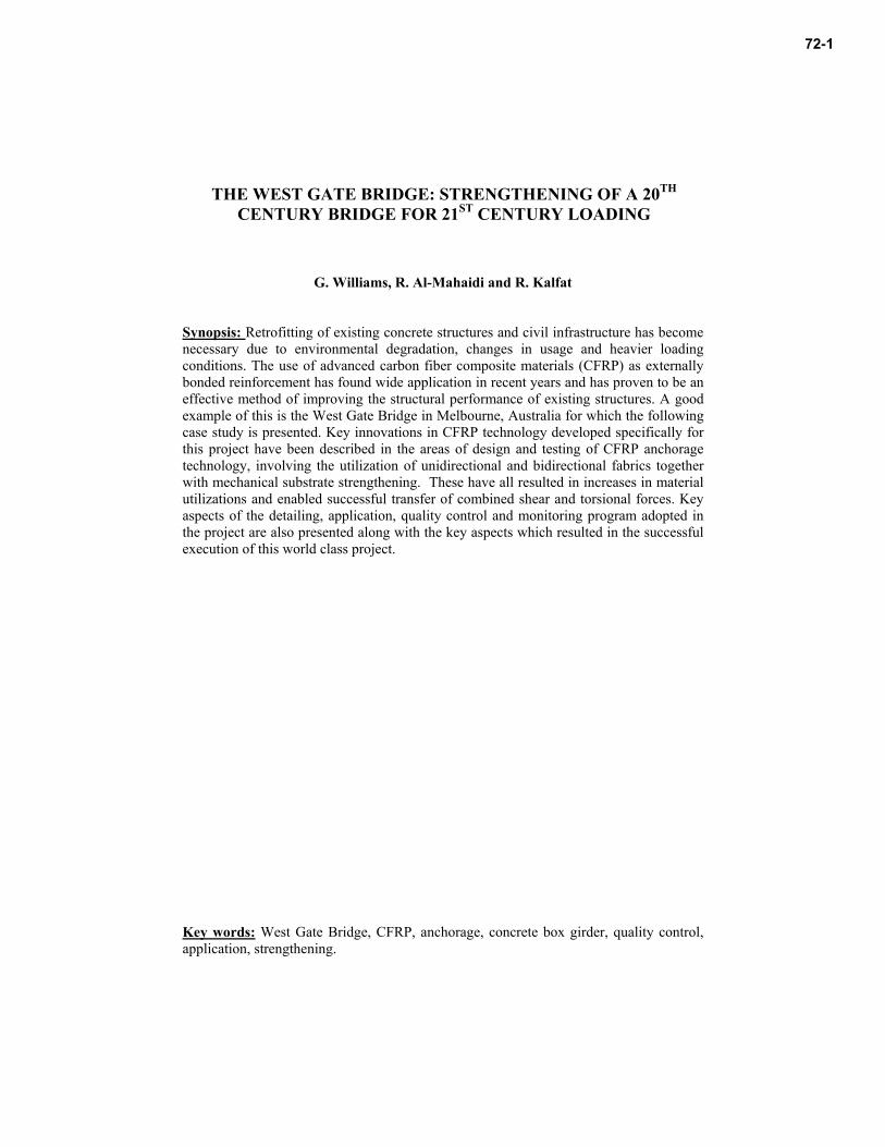
INTRODUCTION The increasing transportation demands of the 21st century have resulted in additional pressures placed on our existing infrastructure to accommodate higher traffic loading and volume requirements. In addition, many concrete bridges currently in use have exceeded their original design life. Together with the introduction of more stringent bridge design and evaluation specifications (AS 5100 2004; BS 5400 1988; AASHTO 1994) has resulted in an increasing number of bridge upgrade and restoration projects. A good example of this is the West Gate Bridge in Melbourne (pictured below), Australia, which is currently one of the largest CFRP strengthening projects in the world (Hii & Al-Mahaidi 2006).
Figure 1 – View of the West Gate Bridge
72-2 Williams et al.
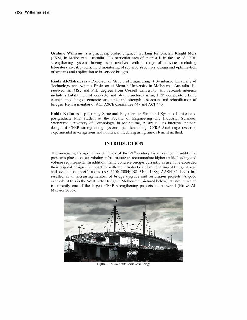
The West Gate Bridge is one of Australia’s most iconic and important links in the national transportation network. The 2.6 km (1.6 mile) structure is comprised of a central steel box girder portion with cable stays, 850m (2,790 ft) in length. Eastern and western approach viaducts, 870m (2,850 ft) and 670m (2,200 ft) long respectively, are composed of segmental pre-stressed concrete box girder sections. In addition, there are minor approach spans which pass over local roads and railway lines, constructed with steel girders and a composite concrete deck which link the viaducts to the West Gate Freeway. The approach viaducts consist of 3 cell pre-cast concrete box segments which were originally assembled span-by-span to form a central spine. Pre-cast transverse cantilevers protrude at right angles from the spine to support the remaining width of the deck. These were erected and post-tensioned to the central spine in order to carry a concrete slab constructed from pre-cast panels and in-situ concrete as shown in Figure 2 below. Although the bridge has been in operation for over 40 years, during this period various rehabilitation measures and structural upgrades have been implemented. Currently a major project is under way to strengthen the bridge in flexure, shear and torsion in order to provide two additional lanes for peak hour traffic. This upgrade was undertaken as part of a consortium known as the West Gate Bridge Strengthening Alliance, including VicRoads, Flint & Neill, SKM and John Holland.
Figure 2 – Exploded View of Concrete Viaduct Components
The West Gate Bridge: Strengthening of a 20th Century Bridge for 21st Century Loading 72-3
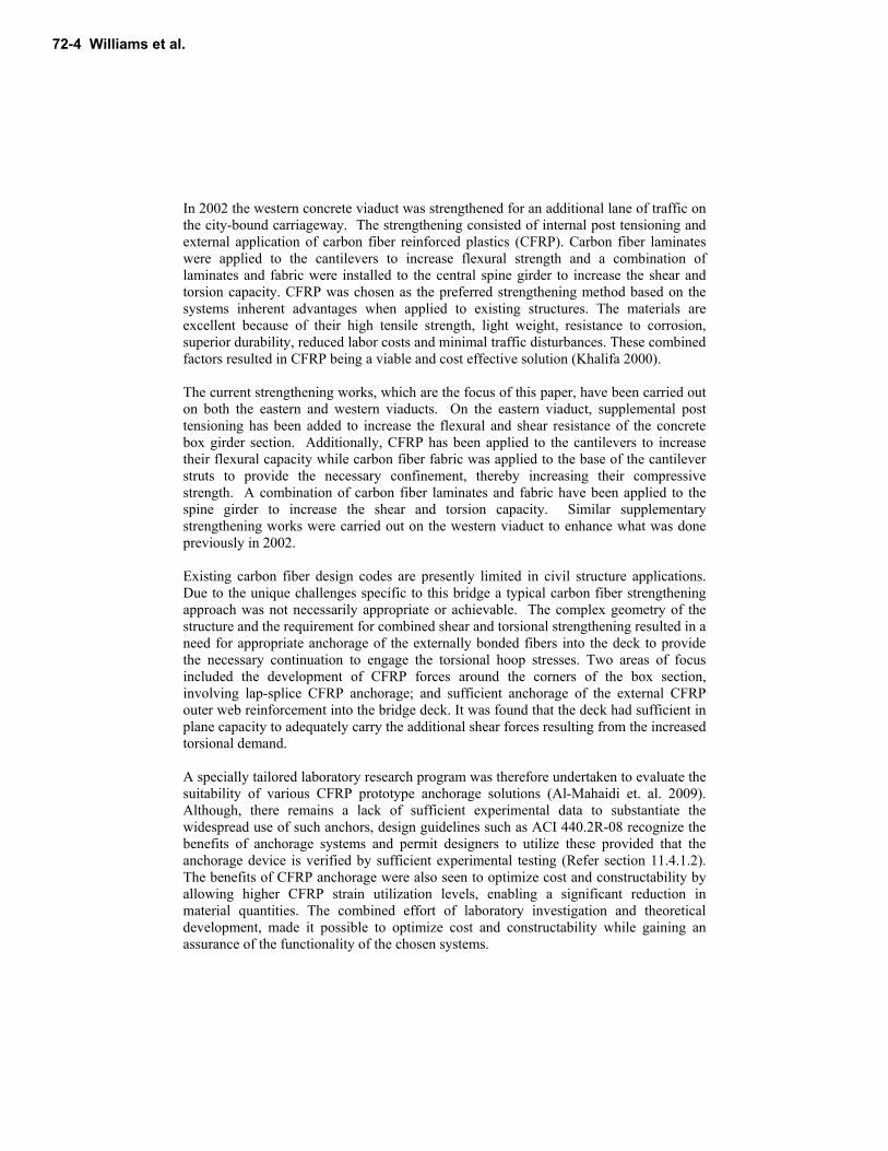
In 2002 the western concrete viaduct was strengthened for an additional lane of traffic on the city-bound carriageway. The strengthening consisted of internal post tensioning and external application of carbon fiber reinforced plastics (CFRP). Carbon fiber laminates were applied to the cantilevers to increase flexural strength and a combination of laminates and fabric were installed to the central spine girder to increase the shear and torsion capacity. CFRP was chosen as the preferred strengthening method based on the systems inherent advantages when applied to existing structures. The materials are excellent because of their high tensile strength, light weight, resistance to corrosion, superior durability, reduced labor costs and minimal traffic disturbances. These combined factors resulted in CFRP being a viable and cost effective solution (Khalifa 2000). The current strengthening works, which are the focus of this paper, have been carried out on both the eastern and western viaducts. On the eastern viaduct, supplemental post tensioning has been added to increase the flexural and shear resistance of the concrete box girder section. Additionally, CFRP has been applied to the cantilevers to increase their flexural capacity while carbon fiber fabric was applied to the base of the cantilever struts to provide the necessary confinement, thereby increasing their compressive strength. A combination of carbon fiber laminates and fabric have been applied to the spine girder to increase the shear and torsion capacity. Similar supplementary strengthening works were carried out on the western viaduct to enhance what was done previously in 2002. Existing carbon fiber design codes are presently limited in civil structure applications. Due to the unique challenges specific to this bridge a typical carbon fiber strengthening approach was not necessarily appropriate or achievable. The complex geometry of the structure and the requirement for combined shear and torsional strengthening resulted in a need for appropriate anchorage of the externally bonded fibers into the deck to provide the necessary continuation to engage the torsional hoop stresses. Two areas of focus included the development of CFRP forces around the corners of the box section, involving lap-splice CFRP anchorage; and sufficient anchorage of the external CFRP outer web reinforcement into the bridge deck. It was found that the deck had sufficient in plane capacity to adequately carry the additional shear forces resulting from the increased torsional demand. A specially tailored laboratory research program was therefore undertaken to evaluate the suitability of various CFRP prototype anchorage solutions (Al-Mahaidi et. al. 2009). Although, there remains a lack of sufficient experimental data to substantiate the widespread use of such anchors, design guidelines such as ACI 440.2R-08 recognize the benefits of anchorage systems and permit designers to utilize these provided that the anchorage device is verified by sufficient experimental testing (Refer section 11.4.1.2). The benefits of CFRP anchorage were also seen to optimize cost and constructability by allowing higher CFRP strain utilization levels, enabling a significant reduction in material quantities. The combined effort of laboratory investigation and theoretical development, made it possible to optimize cost and constructability while gaining an assurance of the functionality of the chosen systems.
72-4 Williams et al.
Once completed, and to the author’s knowledge, the West Gate Bridge will be the largest bridge in the world ever repaired with carbon fiber. In total, nearly 40km (25 miles) of carbon fiber laminates of various grades and dimensions will be applied to the structure along with 11,000 sq. m (118,000 sq. ft) of carbon fiber fabric. At the time of submission of this paper strengthening works were still underway, due to be completed by the end of 2010. The entirety of works will be delivered in approximately 16 months through a combination of innovative solutions that were developed in both design and construction.
RESEARCH SIGNIFICANCE This paper has two main areas of interest to present to the reader; a case study reviewing application of carbon fiber strengthening of an in-service concrete structure and the introduction of carbon fiber detailing based on laboratory investigation. The case study is intended to outline some of the considerations required when using the material as well as some of the issues encountered during in a project of this magnitude. Additionally, it is envisaged this paper will give the reader an idea of the types of uses, advantages and difficulties associated with the current state of the material in industry. Regarding the research program carried out, the results of which were implemented should serve to inform the community at large what possibilities exist for uses of carbon fiber beyond standard detailing practices to date, including higher utilizations of the material strength than when guided by standard codified approaches alone.
DESIGN BASIS
Modeling The West Gate Bridge (WGB) is the primary connection for traffic and freight between the city of Melbourne and western region of the city and state. As such, it was crucial to understand the current and projected traffic volume, magnitude and loading configurations. A thorough review of traffic was conducted and a probabilistic analysis used to develop a Bridge Specific Assessment Criteria Live Load (BSALL) which consisted of a combination of uniformly distributed load (UDL) and discrete axle loads. This loading was applied to both global and local models with load magnitude varying based on the size of the areas being investigated. These models were developed using the software package Sofistik which allowed analysis of the true 3-D geometry of the structures and also incorporated all prestress, time dependent effects such as creep and shrinkage and varying section properties such as shear lag at service limit state (SLS) and the full composite sections at ultimate limit state (ULS). Selection of Material Strengthening of the concrete viaducts required careful consideration of material type, grade and geometry to develop the most appropriate methodology. The most common material used around the world on concrete civil infrastructure projects to date has been unidirectional carbon fiber fabrics delivered through wet layup application. These
The West Gate Bridge: Strengthening of a 20th Century Bridge for 21st Century Loading 72-5
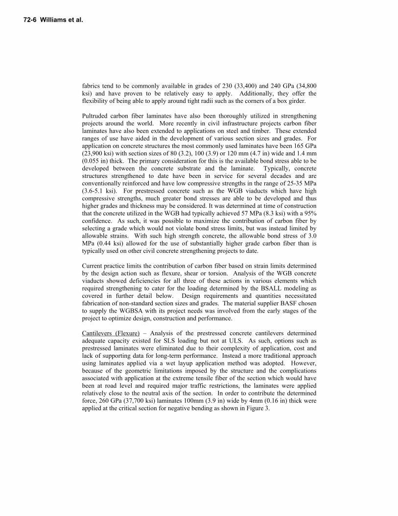
fabrics tend to be commonly available in grades of 230 (33,400) and 240 GPa (34,800 ksi) and have proven to be relatively easy to apply. Additionally, they offer the flexibility of being able to apply around tight radii such as the corners of a box girder. Pultruded carbon fiber laminates have also been thoroughly utilized in strengthening projects around the world. More recently in civil infrastructure projects carbon fiber laminates have also been extended to applications on steel and timber. These extended ranges of use have aided in the development of various section sizes and grades. For application on concrete structures the most commonly used laminates have been 165 GPa (23,900 ksi) with section sizes of 80 (3.2), 100 (3.9) or 120 mm (4.7 in) wide and 1.4 mm (0.055 in) thick. The primary consideration for this is the available bond stress able to be developed between the concrete substrate and the laminate. Typically, concrete structures strengthened to date have been in service for several decades and are conventionally reinforced and have low compressive strengths in the range of 25-35 MPa (3.6-5.1 ksi). For prestressed concrete such as the WGB viaducts which have high compressive strengths, much greater bond stresses are able to be developed and thus higher grades and thickness may be considered. It was determined at time of construction that the concrete utilized in the WGB had typically achieved 57 MPa (8.3 ksi) with a 95% confidence. As such, it was possible to maximize the contribution of carbon fiber by selecting a grade which would not violate bond stress limits, but was instead limited by allowable strains. With such high strength concrete, the allowable bond stress of 3.0 MPa (0.44 ksi) allowed for the use of substantially higher grade carbon fiber than is typically used on other civil concrete strengthening projects to date. Current practice limits the contribution of carbon fiber based on strain limits determined by the design action such as flexure, shear or torsion. Analysis of the WGB concrete viaducts showed deficiencies for all three of these actions in various elements which required strengthening to cater for the loading determined by the BSALL modeling as covered in further detail below. Design requirements and quantities necessitated fabrication of non-standard section sizes and grades. The material supplier BASF chosen to supply the WGBSA with its project needs was involved from the early stages of the project to optimize design, construction and performance. Cantilevers (Flexure) – Analysis of the prestressed concrete cantilevers determined adequate capacity existed for SLS loading but not at ULS. As such, options such as prestressed laminates were eliminated due to their complexity of application, cost and lack of supporting data for long-term performance. Instead a more traditional approach using laminates applied via a wet layup application method was adopted. However, because of the geometric limitations imposed by the structure and the complications associated with application at the extreme tensile fiber of the section which would have been at road level and required major traffic restrictions, the laminates were applied relatively close to the neutral axis of the section. In order to contribute the determined force, 260 GPa (37,700 ksi) laminates 100mm (3.9 in) wide by 4mm (0.16 in) thick were applied at the critical section for negative bending as shown in Figure 3.
72-6 Williams et al.
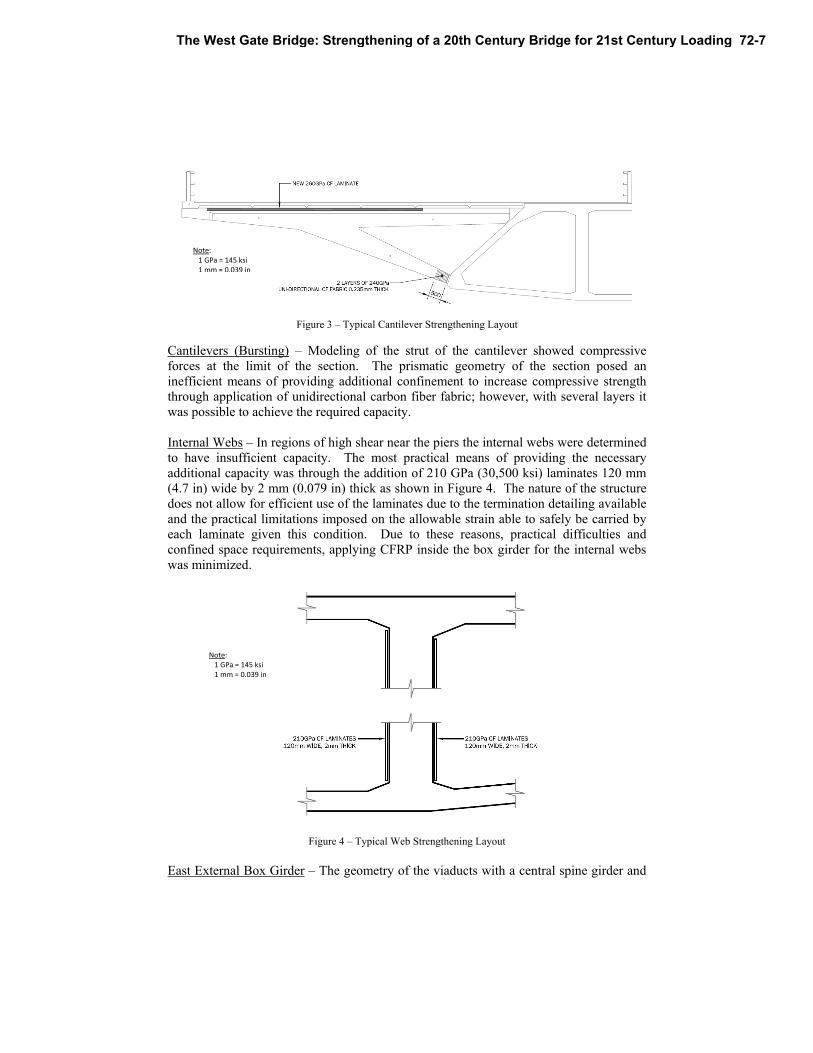
Figure 3 – Typical Cantilever Strengthening Layout
Cantilevers (Bursting) – Modeling of the strut of the cantilever showed compressive forces at the limit of the section. The prismatic geometry of the section posed an inefficient means of providing additional confinement to increase compressive strength through application of unidirectional carbon fiber fabric; however, with several layers it was possible to achieve the required capacity. Internal Webs – In regions of high shear near the piers the internal webs were determined to have insufficient capacity. The most practical means of providing the necessary additional capacity was through the addition of 210 GPa (30,500 ksi) laminates 120 mm (4.7 in) wide by 2 mm (0.079 in) thick as shown in Figure 4. The nature of the structure does not allow for efficient use of the laminates due to the termination detailing available and the practical limitations imposed on the allowable strain able to safely be carried by each laminate given this condition. Due to these reasons, practical difficulties and confined space requirements, applying CFRP inside the box girder for the internal webs was minimized.
Figure 4 – Typical Web Strengthening Layout
East External Box Girder – The geometry of the viaducts with a central spine girder and
Note: 1 GPa = 145 ksi 1 mm = 0.039 in
Note: 1 GPa = 145 ksi 1 mm = 0.039 in
The West Gate Bridge: Strengthening of a 20th Century Bridge for 21st Century Loading 72-7
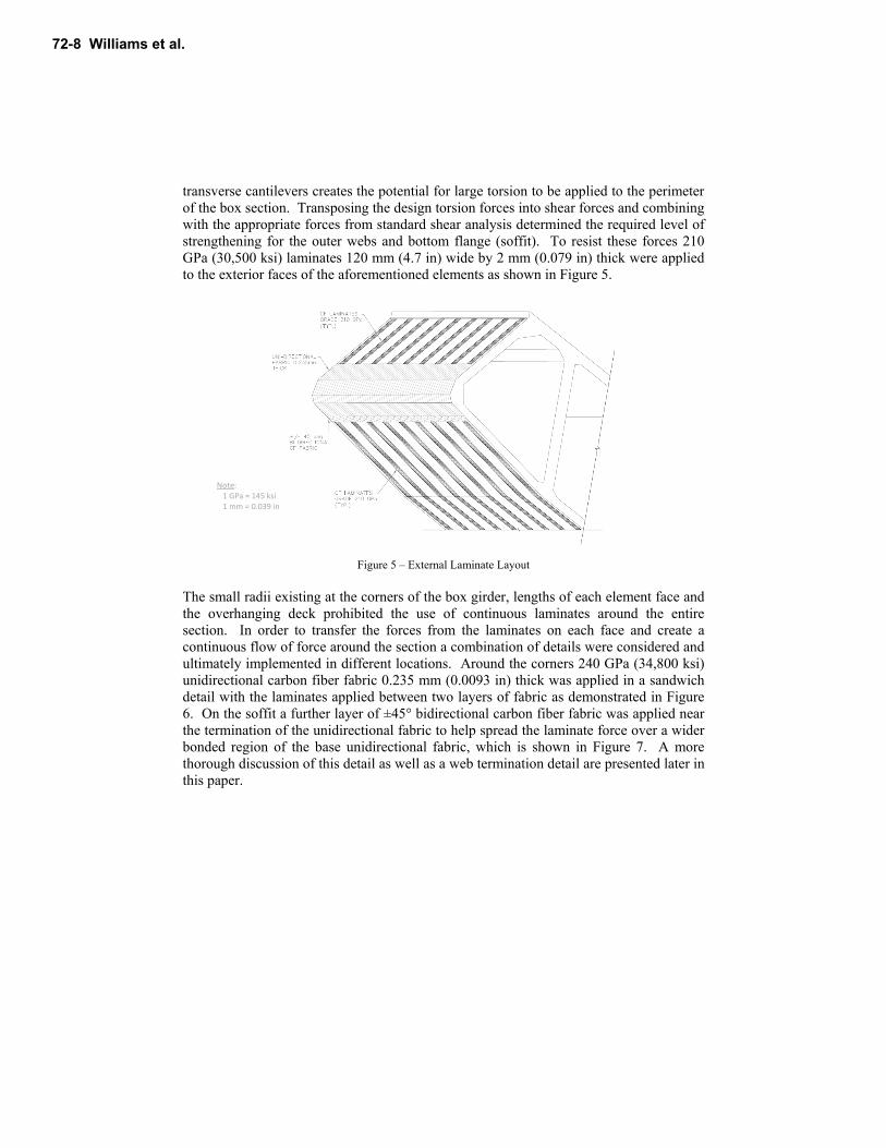
transverse cantilevers creates the potential for large torsion to be applied to the perimeter of the box section. Transposing the design torsion forces into shear forces and combining with the appropriate forces from standard shear analysis determined the required level of strengthening for the outer webs and bottom flange (soffit). To resist these forces 210 GPa (30,500 ksi) laminates 120 mm (4.7 in) wide by 2 mm (0.079 in) thick were applied to the exterior faces of the aforementioned elements as shown in Figure 5.
Figure 5 – External Laminate Layout
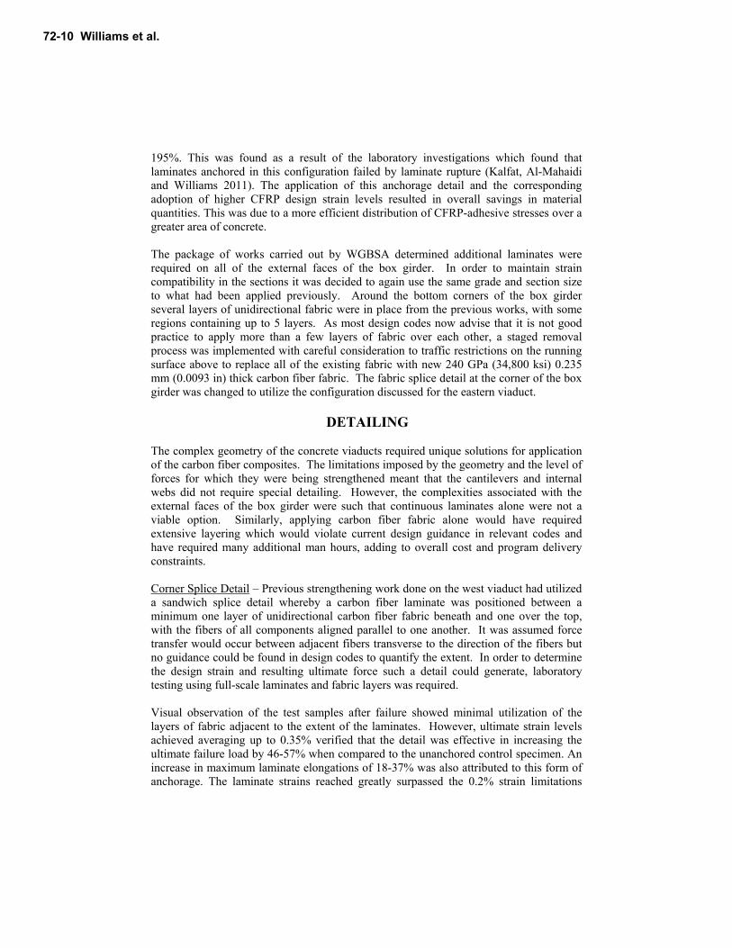
The small radii existing at the corners of the box girder, lengths of each element face and the overhanging deck prohibited the use of continuous laminates around the entire section. In order to transfer the forces from the laminates on each face and create a continuous flow of force around the section a combination of details were considered and ultimately implemented in different locations. Around the corners 240 GPa (34,800 ksi) unidirectional carbon fiber fabric 0.235 mm (0.0093 in) thick was applied in a sandwich detail with the laminates applied between two layers of fabric as demonstrated in Figure 6. On the soffit a further layer of ±45° bidirectional carbon fiber fabric was applied near the termination of the unidirectional fabric to help spread the laminate force over a wider bonded region of the base unidirectional fabric, which is shown in Figure 7. A more thorough discussion of this detail as well as a web termination detail are presented later in this paper.
Note: 1 GPa = 145 ksi 1 mm = 0.039 in
72-8 Williams et al.
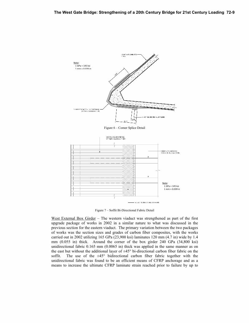
Figure 6 – Corner Splice Detail
Figure 7 – Soffit Bi-Directional Fabric Detail
West External Box Girder – The western viaduct was strengthened as part of the first upgrade package of works in 2002 in a similar nature to what was discussed in the previous section for the eastern viaduct. The primary variation between the two packages of works was the section sizes and grades of carbon fiber composites, with the works carried out in 2002 utilizing 165 GPa (23,900 ksi) laminates 120 mm (4.7 in) wide by 1.4 mm (0.055 in) thick. Around the corner of the box girder 240 GPa (34,800 ksi) unidirectional fabric 0.165 mm (0.0065 in) thick was applied in the same manner as on the east but without the additional layer of ±45° bi-directional carbon fiber fabric on the soffit. The use of the ±45° bidirectional carbon fiber fabric together with the unidirectional fabric was found to be an efficient means of CFRP anchorage and as a means to increase the ultimate CFRP laminate strain reached prior to failure by up to
Note: 1 GPa = 145 ksi 1 mm = 0.039 in
Note: 1 GPa = 145 ksi 1 mm = 0.039 in
The West Gate Bridge: Strengthening of a 20th Century Bridge for 21st Century Loading 72-9
195%. This was found as a result of the laboratory investigations which found that laminates anchored in this configuration failed by laminate rupture (Kalfat, Al-Mahaidi and Williams 2011). The application of this anchorage detail and the corresponding adoption of higher CFRP design strain levels resulted in overall savings in material quantities. This was due to a more efficient distribution of CFRP-adhesive stresses over a greater area of concrete. The package of works carried out by WGBSA determined additional laminates were required on all of the external faces of the box girder. In order to maintain strain compatibility in the sections it was decided to again use the same grade and section size to what had been applied previously. Around the bottom corners of the box girder several layers of unidirectional fabric were in place from the previous works, with some regions containing up to 5 layers. As most design codes now advise that it is not good practice to apply more than a few layers of fabric over each other, a staged removal process was implemented with careful consideration to traffic restrictions on the running surface above to replace all of the existing fabric with new 240 GPa (34,800 ksi) 0.235 mm (0.0093 in) thick carbon fiber fabric. The fabric splice detail at the corner of the box girder was changed to utilize the configuration discussed for the eastern viaduct.
DETAILING The complex geometry of the concrete viaducts required unique solutions for application of the carbon fiber composites. The limitations imposed by the geometry and the level of forces for which they were being strengthened meant that the cantilevers and internal webs did not require special detailing. However, the complexities associated with the external faces of the box girder were such that continuous laminates alone were not a viable option. Similarly, applying carbon fiber fabric alone would have required extensive layering which would violate current design guidance in relevant codes and have required many additional man hours, adding to overall cost and program delivery constraints. Corner Splice Detail – Previous strengthening work done on the west viaduct had utilized a sandwich splice detail whereby a carbon fiber laminate was positioned between a minimum one layer of unidirectional carbon fiber fabric beneath and one over the top, with the fibers of all components aligned parallel to one another. It was assumed force transfer would occur between adjacent fibers transverse to the direction of the fibers but no guidance could be found in design codes to quantify the extent. In order to determine the design strain and resulting ultimate force such a detail could generate, laboratory testing using full-scale laminates and fabric layers was required. Visual observation of the test samples after failure showed minimal utilization of the layers of fabric adjacent to the extent of the laminates. However, ultimate strain levels achieved averaging up to 0.35% verified that the detail was effective in increasing the ultimate failure load by 46-57% when compared to the unanchored control specimen. An increase in maximum laminate elongations of 18-37% was also attributed to this form of anchorage. The laminate strains reached greatly surpassed the 0.2% strain limitations
72-10 Williams et al.
imposed by current CFRP design guidelines. Additionally, an interesting outcome appeared when reviewing the strains achieved over the length of the splice. In the laboratory samples the lap length was limited to 400mm (15.7 in) with strain gauges positioned at regular intervals along the length of the splice. As the failure strain was approached it was observed that the strain along the splice varied from a more traditional bond length of less than 300mm (11.8 in) to utilizing the entire length of the laminate, suggesting that a longer splice length may potentially offer the benefit of achieving higher strains (Kalfat, Al-Mahaidi and Williams 2011). Another option investigated was the use of ±45° bidirectional CFRP fabric, for which additional samples were fabricated and tested. It was anticipated that by transferring forces from the laminates at a somewhat gentle angle rather than relying on purely transverse distribution of load between parallel fibers, a greater area of bond with the concrete substrate might result in higher strains achieved in the laminates. Since the application of unidirectional fabric with an orientation parallel to the direction of the laminate had resulted in a transfer of bond stress to a greater length away from the loaded edge, a specimen was tested to utilize and improve the benefits of this arrangement by the addition of a single layer of ±45° bidirectional fabric to the two layers of unidirectional fabric present in the corner splice detail. This resulted in a distribution of fiber-to-adhesive bond stresses over a greater length and width of concrete achieving an increase in failure load of 195% and resulting in laminate rupture. Deck Soffit Detail – Ultimately, any increase in allowable design strains was subject to both ends of the laminate having suitable anchorage details to enable a higher design strain to be adopted. As such, additional end anchorage alternatives were investigated for laminate termination locations near the deck soffit. A traditional approach commonly used in shear strengthening detailing of T-beams includes a layer (or layers) of unidirectional fabric transverse to the shear strengthening material, parallel to the deck was considered. Additionally, a detail involving the installation of a bar which could be inserted into the deck was devised and tested. Results from testing of the traditional detailing transverse fabric option proved additional anchorage capacity for the laminate design strain could be realized when compared with a simple end termination based on design code evaluation. By anchoring the CFRP laminate in this manner, increases in the ultimate failure load of 39-43% and maximum laminate strain increases of 19-28% were observed prior to failure when compared to the control specimen. The higher load carrying capacity was believed to be due in part to the 50mm tapper of laminate adhesive which was applied to the edges of the laminate distributing the laminate-adhesive stresses to a greater width of concrete. The results suggest that the application of CFRP fibers perpendicular to the direction of loading was unsuccessful in the transfer of laminate forces over a greater width of concrete and provided a minimal level of confinement. Several test specimens where therefore constructed using ±45° bi-directional CFRP fabric which was anticipated to be more effective. The laboratory results demonstrated that a single ply of bidirectional fabric anchored 50mm (2 in) down the sides of the concrete block was effective in increasing the ultimate failure load by 128%, whereas the use of 2 plies of bidirectional fabric with
The West Gate Bridge: Strengthening of a 20th Century Bridge for 21st Century Loading 72-11
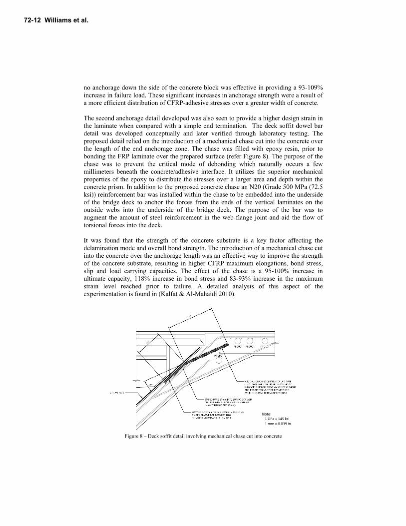
no anchorage down the side of the concrete block was effective in providing a 93-109% increase in failure load. These significant increases in anchorage strength were a result of a more efficient distribution of CFRP-adhesive stresses over a greater width of concrete. The second anchorage detail developed was also seen to provide a higher design strain in the laminate when compared with a simple end termination. The deck soffit dowel bar detail was developed conceptually and later verified through laboratory testing. The proposed detail relied on the introduction of a mechanical chase cut into the concrete over the length of the end anchorage zone. The chase was filled with epoxy resin, prior to bonding the FRP laminate over the prepared surface (refer Figure 8). The purpose of the chase was to prevent the critical mode of debonding which naturally occurs a few millimeters beneath the concrete/adhesive interface. It utilizes the superior mechanical properties of the epoxy to distribute the stresses over a larger area and depth within the concrete prism. In addition to the proposed concrete chase an N20 (Grade 500 MPa (72.5 ksi)) reinforcement bar was installed within the chase to be embedded into the underside of the bridge deck to anchor the forces from the ends of the vertical laminates on the outside webs into the underside of the bridge deck. The purpose of the bar was to augment the amount of steel reinforcement in the web-flange joint and aid the flow of torsional forces into the deck. It was found that the strength of the concrete substrate is a key factor affecting the delamination mode and overall bond strength. The introduction of a mechanical chase cut into the concrete over the anchorage length was an effective way to improve the strength of the concrete substrate, resulting in higher CFRP maximum elongations, bond stress, slip and load carrying capacities. The effect of the chase is a 95-100% increase in ultimate capacity, 118% increase in bond stress and 83-93% increase in the maximum strain level reached prior to failure. A detailed analysis of this aspect of the experimentation is found in (Kalfat & Al-Mahaidi 2010).
Figure 8 – Deck soffit detail involving mechanical chase cut into concrete
Note: 1 GPa = 145 ksi 1 mm = 0.039 in
72-12 Williams et al.
APPLICATION / QUALITY CONTROL To ensure carbon fiber composite systems are able to perform as designed strict quality control measures must be in place during application. For many structures application of these systems is performed on cast in-situ conventionally reinforced concrete with potentially large surface irregularities. For application on precast where potentially greater confidence exists in the flat profiles which may have been achieved there is still some degree of risk in encountering unevenness. Grinding, grit blasting, or any other form of mechanical profiling of surfaces to remove high spots introduces the risk of reduced cover for the internal reinforcement which is undesirable. The alternative to this is to fill depressed regions with an appropriate material capable of enabling the carbon fiber composite strengthening system to carry the intended forces. Excessive build-up of a filling agent to achieve a straight profile generally can come in two forms; cementitious and epoxy based. Particularly in overhead applications, finding a cementitious material capable of achieving sufficient bond strength both between itself to the concrete substrate and also between itself and the overlaying carbon fiber composite system may be difficult and even more difficult to test as in small regions destructive testing may remove a substantial portion of the leveling work. Use of excessive amounts of epoxy based agents for leveling surfaces may be even less attractive as little guidance is yet available in design codes regarding their long-term performance as well as the mechanical performance based on their relatively weak strength characteristics compared with the carbon fiber composites which they are bonding to the concrete substrate. An additional alternative to grinding and filling is simply applying carbon fiber composites directly onto the surface of the substrate without any leveling works and allowing the system to match the existing profile of the structure. This option is perhaps the easiest from a constructability point of view but potentially the worst from a performance viewpoint. Particularly in concave regions, the epoxy adhesives would be required to transfer forces from the carbon fiber components in shear into the concrete substrate and also act in direct tension as the carbon fiber system attempts to straighten and pull away from the structure. A thorough review was conducted by the WGBSA of available guidance in design codes, manufacturers’ specifications and academic research and reporting to determine acceptable limits of both deviation from flatness and allowable build-up of epoxy bonding agents. The result was a combination of allowable limits including deviation from straightness, depth of epoxy fillers and extent over which particular depths could extend to achieve a final product within specified tolerances capable of enabling the systems to perform as designed. Allowable Concave Deviation – Review of design codes to determine allowable limits of concavity found variations between all of the major publications. The design was carried
The West Gate Bridge: Strengthening of a 20th Century Bridge for 21st Century Loading 72-13
out using the British Concrete Society Technical Report No. 55 2004 with guidance from ACI 440.2R-08 2008, so the tolerances were based on a combination of advice provided within these codes, as well as the standard specification for the application of fiber reinforced polymer composites (FRPC) published by the state road authority VicRoads. Standard flatness checks were carried out using a 300mm (11.8 in) (Fib: Task Group 9.3 2001) straight edge and a 2m (79 in) straight edge, with allowable deviations against each of the straight edges being 1mm (0.039 in) and 10mm (0.39 in) respectively. Allowable Build-up of Epoxy – The project material supplier was able to provide a wide range of epoxies with slightly different properties for different applications. For regions requiring greater than a leveling skim coat epoxy products were adopted which could be supplemented with small aggregate to provide high compressive strengths and a surface more closely reflecting the properties of concrete. Due to the uncertainty associated with excessive thicknesses of epoxy including long-term durability and shear deformations, it was decided to limit the thickness in any localized area to 5mm (0.20 in). A localized area was then specified as a linear distance no greater than 1m (39.4 in). Additionally, as a result of the high bond stresses in anchorage zones, adhesive thicknesses were limited to 3mm (0.12 in) within 500mm (19.7 in) of the end of any laminate. Typical application guidelines from any manufacturer recommend adhesive thicknesses between 1.5 to 2 mm (0.059 to 0.079 in) for bonding laminates to concrete substrate (Concrete Society Technical Report No. 55 2004; Fib: Task Group 9.3 2001). As such, careful consideration was required during construction to ensure a balance was achieved between the localized build-up of epoxy and the concavity of the surface of the final product. Performance Evaluation – Quality control monitoring on the project required destructive testing to satisfy acceptability of the components and systems that were installed. Each of the individual components were tested with laminates and fabrics subjected to standard tensile tests, epoxies tested via cube strengths to ensure compressive strengths were achieved, and direct tensile pull-off tests of the FRPC systems bonded to the viaducts. Tensile tests of the laminates and fabrics were conducted for each batch, grade and section size. The 210 GPa (30,500 ksi) laminates 120mm (4.7 in) wide by 2mm (0.079 in) thick and the 260 GPa (37,700 ksi) laminates 100mm (3.9 in) wide by 4mm (0.16 in) thick were non-standard sizes and project specific dyes were required in order for their pultrusion. A reasonable number of samples were taken of each to ensure the strict quality control measures implemented during processing resulted in a final product with values used for design. Cube strength tests of the epoxies provided a straight forward and relatively easy means of verifying the manufacturers quoted strength properties were being achieved. A high frequency of sampling was conducted early in the construction process to determine a baseline performance and as a greater confidence was gained in the consistent performance of the epoxies the testing was later relaxed.
72-14 Williams et al.
Direct tensile pull-off tests were conducted to verify the minimum performance of the strengthening system was achieved. Ultimately, the pull-off tests provided the highest level of confidence that the system was able to perform as designed. Unfortunately, this type of destructive testing would typically have damaged the system which was being applied to resist the traffic loading. In order to minimize the impact on the strengthening system, sacrificial testing strips were applied at regular intervals adjacent to the final works to ensure the adequate level of care was being taken in application of the various carbon fiber elements. Additionally, legacy testing strips were applied near each pier to allow VicRoads, the asset owner, to come back periodically and perform additional testing. The hope was to determine a baseline performance at time of installation against which future test results could be compared to determine if any reason for concern in the systems durability is noticed. Rectification of Drummy Areas – At the completion of application of the CFRP system in all locations, thorough surface tap (or hammer) tests were carried out to check for drumminess. When a drummy area was located in any of the carbon fiber components a drill with a small bit (generally 2mm (0.079 in) diameter) was used to create a hole at each end of the drummy area. A syringe was then used to inject a suitable adhesive filler to treat the region and allow the transfer of forces between the carbon fiber and substrate. When treating laminates care was taken to create holes the same distance from the edge of the section transverse to the direction of fibers to minimize the number of individual fibers intersected. In regions of carbon fiber fabric that were found to exhibit drumminess, typically the weave of the fabric allowed for easy treatment with minimal reduction in fibers to remediate drummy areas.
CONCLUSION
There are a number of constraints and opportunities which need to be investigated when carrying out any bridge strengthening or rehabilitation project. Ultimately a balance must be achieved between practicality, site access, delivery including cost and program, resources, etc. Based on the work included as part of the strengthening of the concrete viaducts of the West Gate Bridge the following conclusions can be drawn: When managed efficiently through both innovative design and construction
techniques a large volume of work was able to be completed within a tight time frame;
Design guidelines can limit the CFRP material strains to levels as low as 10-25% of the ultimate material strain at rupture.
There is to date a general lack of guidance available in design codes and commentary regarding the efficient use of connection detailing with CFRP.
Laboratory investigation of connection details provided the potential for substantial savings in time and budget;
The use of unidirectional and bidirectional fabric as a means of creating a greater bond area with the concrete substrate allowed substantially higher utilization of carbon fiber laminates beyond a standard codified design approach;
The West Gate Bridge: Strengthening of a 20th Century Bridge for 21st Century Loading 72-15
The introduction of a mechanical chase cut into the concrete over the anchorage length is an effective way to improve the strength of the concrete substrate, resulting in higher CFRP maximum elongations, bond stress, slip and load carrying capacities
The challenges faced with any CFRP project were heightened by the uniqueness of the bridge geometry and the large scale of application. This resulted in the necessity for strict application and quality control procedures, which resulted in the introduction of measures to control: allowable concave deviation, allowable build-up of epoxy, performance evaluation and procedures for the rectification of drummy areas.
ACKNOWLEDGEMENTS
The authors would like to mention the following organizations for their contributions to the project and to this paper: Vicroads, Monash University, BASF, SKM and John Holland; and also a special thank you to the following individuals: Michael Malicki, Anthony Brasacchio, Andrew Sarkady and Matthew Sentry.
72-16 Williams et al.
REFERENCES AASHTO 1994, 'Standard Specifications for Highway Bridges', AASHTO, Washington, D.C. ACI 440.2R-08 2008, 'Guide for the Design and Construction of Externally Bonded FRP Systems for Strengthening Concrete Structures', American Concrete Institute, Farmington Hills, Michigan. Al-Mahaidi, R, Sentry, M. & Williams, G 2009, 'Testing the Efficiency of Anchorage Systems Applied to CFRP Laminate Strips Bonded to Concrete - West Gate Bridge Strengthening Project', Department of Civil Engineering Report, Monash University, Melbourne, Australia, 93pp. AS5100-04 2004, 'Bridge Design', Standards Australia International Ltd., Sydney, NSW. BS 5400 1988, 'Steel, concrete and composite bridges', BSI, London. Concrete Society Technical Report No. 55 2004, 'Design guidance for strengthening concrete structures using fibre composite materials, Second Edition', ISBN 1 904482 14 7. Fib: Task Group 9.3, B 2001, 'Externally Bonded FRP Reinforcement for RC Structures.', International federation for structural concrete, Lausanne, Switzerland. Hii, AKY & Al-Mahaidi, R 2006, 'Experimental Investigation on Torsional Behavior of Solid and Box-Section RC Beams Strengthened with CFRP Using Photogrammetry', Journal of Composites for Construction, vol. 10, no. 4, pp. 321-9. Kalfat R & Al-Mahaidi R 2010, 'Investigation into bond behaviour of a new CFRP anchorage system for concrete utilising a mechanically strengthened substrate. ', Compos Struct (2010), doi:10.1016/j.compstruct.2010.04.004. Khalifa, A, Belarbi, A, and Nanni, A, 2000, 'Shear Performance of RC Members Strengthened with Externally Bonded FRP Wraps', Proc., 12th World Conference on Earthquake Engineering, Auckland, New Zealand, paper 305,10 pp. R. Kalfat R. Al-Mahaidi and G. Williams 2011, 'Investigation of efficient anchorage systems for shear and torsion retrofitting of box girder bridges', FRPRCS-10, International Symposium on Fiber Reinforced Polymer Reinforcement for Reinforced Concrete Structures, Tampa, Florida, USA.
The West Gate Bridge: Strengthening of a 20th Century Bridge for 21st Century Loading 72-17

72-18 Williams et al.