Embed Size (px)
Citation preview
The Wallbot: A Low-cost Robot for Green Wall Inspection
Marc Carmichael, Richardo Khonasty, Sara Wilkinson, Tim SchorkUniversity of Technology Sydney, Australia
Abstract
The benefits of urban green infrastructure, suchas attenuating the urban heat island effect andimproving air quality, are widely accepted. Re-gardless, the uptake of green walls (i.e. verticalgardens) is low due to the high costs relatingto maintenance and OH&S. These barriers toadoption may be mitigated by using robotics toinspect and maintain green walls.
In this work we present the Wallbot, a roboticsystem to inspect, monitor and aid in the main-tenance of green walls. In its current formthe system comprises of affordable off-the-shelfcomponents to keep the system cost low. Pre-liminary development of the system, results ofinitial tests and findings are presented. Thesystem offers the chance to reduce OH&S issuesand maintenance costs associated with greenwalls.
1 Introduction
There are many reasons to increase the amount of GreenInfrastructure (GI) in cities and urban areas. A key mo-tivation is to decrease the environmental impact of thebuilt world. Urban Heat Island (UHI) is a phenomenonwhere ambient temperatures are found to be higher indensely populated areas compared to the surroundingareas. UHI was found to affect the temperature by upto 11oC in Sydney, Australia [Santamouris et al., 2017].One of the causes of UHI is the reduction of vegetationin these areas. One method of reducing the UHI effectis through increasing Green Infrastructures (GI) such asGreen Roofs (GR), Green Walls (GW) and Green Fa-cades (GF). A Macquarie University study and 2014UTS Institute of Sustainable Futures report showed 6oCheat mitigation is possible through GI [Jacobs et al.,2016], [Ossola et al., 2020]. An intangible benefit ofgreen infrastructure are biophilia effects, with humanshaving an innate need to experience the natural world
and associated feelings of well-being [Orr and Wilkin-son, 2017]. A tangible benefit is an increased propertyvalue associated with green infrastructure and property[Rosenwax, 2017].
Although there are many benefits, the adoption rateof GI, and especially GW, is low [Wilkinson and Dixon,2016]. This is largely attributed to the high costs asso-ciated with GW maintenance. Maintenance operationsrequire workers, often qualified horticulturists, to closelyinspect the condition of the plants on the green wall, andperform interventions such as pruning and replanting.Since GW are typically part of a building’s facade, theseworkers are required to work at heights. Methods suchas using scissor lifts, Building Maintenance Units in thecase of larger buildings, or abseiling are often needed togain access, further adding to the costs associated withGW maintenance.
By reducing the cost of maintenance, the adoption ofGW should be increased and in turn lead to the associ-ated benefits. One way of reducing the maintenance costis through the use of an automated system to aid workersin maintenance operations. A robotic system that canreduce the amount that humans are needed to physicallyscale the side of buildings, even a partial reduction, couldsignificantly reduce the overall maintenance cost acrossthe life-cycle of the green infrastructure.
In this work we present the initial developments of theWallbot, a robotic system for aiding in the inspectionand maintenance of green walls. The Wallbot has beendeveloped with cost in mind, utilising relatively inex-pensive and off-the-shelf components to form the system.Conception was based on workshops held with green wallstakeholders to understand the needs and nuances of endusers. Robotics has been explored extensively for use inagriculture [Roldan et al., 2018], and systems specificallyfor GW have been devised [Fraunhofer IPA, 2020]. How-ever to the best knowledge of the authors, this work isthe first physical robotic system developed for the pur-pose of aiding green wall maintenance.
The remainder of this manuscript is organized as fol-
lows. Section 2 presents the outcomes from two work-shops that assisted in defining the scope for automatingGW maintenance. In Section 3, options for wall climbingsystems are reviewed. Section 4 details the developmentof the Wallbot prototype system. In Section 5 prelim-inary results obtained are discussed. The future worksof the the Wallbot prototype are listed in Section 6 andthe conclusion of the paper is summarized in Section 7.
2 Design Workshops
To better understand the requirements and constraintsassociated with automating GW maintenance, two de-sign workshops were hosted with key stakeholders. Thisincluded green wall installers and designers, landscapearchitects, building certifiers, urban planners, robot de-signers, IoT professionals and horticultural scientists.
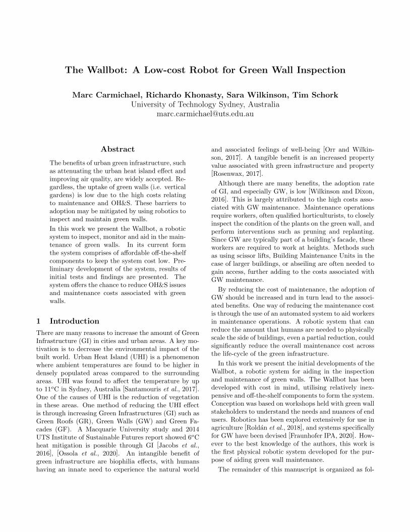
In the two workshops, potential embodiment of theWallbot was discussed. Various design concepts were ex-plored in relation to the social, economic, environmental,regulatory, legal and technological impact. Based on theworkshop discussions it became clear that it would bedifficult for a one-size-fits-all automated system to caterto all GW. For example, a GW installed on a large build-ing such as one shown in Figure 1a may require frequentmaintenance and would benefit from a permanent instal-lation integrated into the building. In contrast, a smallerGW like that shown in Figure 1b may benefit from tem-porary installation of the automated system which maybe shared across several locations.
The key feature deemed important by the stakeholdersinvolved in the workshops was the capability of monitor-ing the health of the plants. Additional functions suchas planting and pruning, which requires physical inter-action with the GW, were deemed desirable but not nec-essary in this early stage of development which reducesthe complexity of the Wallbot system. For ease of ini-tial testing, it was also decided that the Wallbot systemshould be designed to be transportable from one GWsite to another, rather than a large permanent installa-tion specific to a particular site.
3 Wall climbing robot options
There has been many different robotic prototypes thatwere designed to inspect and maintain large structures.Although these robots have not yet been implemented ona GW, the core mechanics involved in developing theserobots in their specific application may be transferableto a GW monitoring and maintenance system.
One method of locomotion for climbing robots isthrough the use of adhesion to the surface to be climbed.Through the use of magnetic footpads, a robot inspiredby the inch-worm was developed to inspect steel bridges[Ward et al., 2014]. The Sky Cleaners [Zhang et al.,
(a) One Central Park, Chippendale
(b) UTS Building 10
Figure 1: A comparison of two green wall installationson the side of large buildings.
2007] used vacuum suction as a method of adhesion toglass surfaces such that the robot could be used for glass-wall cleaning in high rise buildings. Because these typeof robots require contact to the surface for locomotion,in the context of the GW contact, to the surface is un-favourable. By requiring contact to the surface, there isa higher risk to cause damage to the plants. Thereforeit is unlikely for the Wallbot prototype to move aroundthe GW through adhesion.

Another common method of inspection is through theuse of Unmanned Aerial Vehicles (UAV). The UAV hasbeen used in a wide variety of applications such as bridgeinspection [Seo et al., 2018]. In [Dang et al., 2018], aUAV was used to detect disease in radish fields, allowingfor timely intervention to minimize losses. The benefit ofthe UAV is the capability to be used on a large number ofGW with minimal additional infrastructure needed. Thedownside of these type of systems is the limited payload,resulting in a system that is mainly limited to inspectionoperations. Furthermore, with GW sometimes being lo-cated on residential buildings the use of UAV raises aconcern over safety and privacy.
Cable driven robots have benefits including high pay-load to weight ratio, large workspace and transportabil-ity [Bosscher et al., 2006]. These robots have been usedin a wide variety of applications such as performing vi-sual inspection on the top of airplanes [Monich et al.,2019] to systems mounted on the side of buildings tomonitor the environment [Izard et al., 2013], and cleanwindows [Elkmann et al., 2005]. Unlike UAVs these typeof robotic systems require some infrastructure to be in-stalled onto the GW itself.
Based on the key features identified from the twoworkshops, it was decided that the Wallbot prototypeshould be a cable driven robot. Although these typeof robotic systems require some infrastructure to be in-stalled onto the GW, it provides a higher payload capac-ity compared to UAVs. This allows the Wallbot proto-type to be expanded with desirable maintenance func-tions to be developed in the future.
4 The Wallbot Prototype
The Wallbot prototype (Figure 2) comprises of two coreelements; a set of four smart winches used to controlmovements of the Wallbot across the green wall; andthe main body containing the sensors that are used todevelop a map of the green wall and inspect the plants.
Two key factors dictated the elements of the proto-type. The first is that the cost needs to be kept low suchthat the expense would incentivise the uptake of GW.The second design factor is safety as GW are usuallyinstalled in public spaces.
4.1 Smart Winch
The smart winchs consist of several elements as shownin Figure 3. To keep the cost of the prototype low, anoff-the-shelf automotive winch was used. Added to thewinch shaft is an encoder which allows the drum positionto be accurately measured and the length of the rope es-timated. Inside the smart winch, the rope is fed througha series of pulleys which is positioned such that the ten-sion of the cable can be measured through the use of theload cell.
Figure 2: The Wallbot prototype, consisting of foursmart winches and a main body.
Figure 3: The components of a smart winch responsiblefor the positioning of the Wallbot main body.
To control the rotational speed of the winch, a mi-crocontroller (Teensy 3.2) was used alongside a motordriver. By rotating the four smart winches, the lengthfour ropes attached to the Wallbot main body is able tobe changed to achieve locomotion. The microcontrolleris also responsible for tracking the state of the smartwinch, such as the tension of the cable being measuredby the load cell, as well as the position and velocity ofthe winch. The state of each smart winch is passed onto a desktop computer which is then used for the highlevel control of the Wallbot prototype.
4.2 Rope and Pulley arrangement
As safety was a major concern for the system, syntheticrope was utilised. The synthetic rope was chosen overthe steel counterpart as it allowed for sufficient tensionto be maintained to lift and manoeuvre the Wallbotmain body, whilst limiting the potential damage in casea break was to occur.
In the experimental setup, all four smart winches arelocated on the ground as shown in Figure 2. The ropes

are fed up to pulleys that are mounted on the wall to-wards each corner of the green wall. We refer to the lo-cation of these pulleys as the anchor points on the wallas they anchor the robot to the wall and their locationsdefine the kinematic relationship between Wallbot poseand rope length. It is envisioned that future iterationsof the Wallbot, the winches may be mounted directly onthe wall and form part of the GW installation.
4.3 Main Body
The structure of the Wallbot prototype main body (Fig-ure 4 is made from a rigid aluminium frame providingfour cable mounting points. These mounting points al-low the ropes of the smart winches to be attached to themain body. The rigid frame is also used to house threevision-based sensors, which are:
• Intel RealSense T265
• Intel RealSense D435
• MAPIR Survey 3
Figure 4: The main body of the Wallbot.
The Intel RealSense T265 camera was used to providetracking information using stereo vision and its inbuiltIMU. This information is able to be used to improvethe accuracy of the motion performed by the Wallbot,even when the length of the ropes is uncertain, for ex-ample due to rope stretching. When combined with thedepth information provided by the Intel RealSense D435,a high fidelity 3D map of the GW can be reconstructed.
The MAPIR Survey 3 camera is used to provide a mul-tispectral image to compute the Normalized DifferenceVegetation Index (NDVI) of the green wall. Camerasused to compute NDVI are commonly used to make re-mote measurements and assessment of vegetation. UsingNDVI, UAVs can autonomously collect data and recog-nize crop health. The Wallbot system takes NDVI mea-surements for a similar purpose, except the vegetation isvertical and the measurements are take at close distance.
The three sensors are positioned inside the Wallbotmain body in such a way that the field of view over-lap as much as possible and the area in which all three
sensors are active can be maximized. The main bodyis designed to be modular and expandable, allowing foradditional sensors to be integrated. For example, inte-grating a temperature and humidity sensor could provideadditional information to be obtained, useful for planthealth monitoring.
4.4 Robot Control
The control system architecture of the Wallbot proto-type is divided into two levels as shown in Figure 5.The high-level control dictates the movement to be per-formed by the Wallbot prototype. The low-level controlprovides a direct interface to the hardware of the smartwinch.
Figure 5: Flowchart of the control system of the Wallbotprototype.
High Level control
The high-level control is used to calculate the desiredvelocity of the four smart winches based on the currentposition and desired velocity of the Wallbot main body.To simplify the calculation the Wallbot is assumed tobe constrained to a plane at a set distance parallel tothe wall. With the location of the anchor points on thewall know, the relationship between the Wallbot bodypose x = [x, y, θ]T and the rope lengths from the bodyto anchor points l = [l1, l2, l3, l4]T can be calculated witha simple kinematic relationship:
l = F (x)−1 (1)

Note that we consider this as the inverse kinematicrelationship, considering the length of the rope (fromWallbot body to anchor point) being the generalised co-ordinates of the system. The time derivative of this re-lationship leads to the following:
l = J−1x (2)
J−1 =
l1,x, l1,y, −r1,y l1,x + r1,x l1,yl2,x, l2,y, −r2,y l2,x + r2,x l2,yl3,x, l3,y, −r3,y l3,x + r3,x l3,yl4,x, l4,y, −r4,y l4,x + r4,x l4,y
(3)
Where J is the Jacobian matrix relating the speed ofthe Wallbot body to the speed of the rope. l repre-sents the unit vector with a direction which is alignedto the corresponding rope, noted by the numerical sub-script. The subscript x and y represents the horizontaland vertical component of the unit vector. r representsthe vector that extends from the Wallbot main bodycenter of rotation to the corresponding cable mountingpoints. Given a desired Wallbot body pose and veloc-ity, corresponding rope lengths and rope speeds can becomputed. These are then sent as command set-pointsto the four smart winches.
A challenge with controlling the rope length and speedis that the effective diameter of each winch drum isnot constant. As the winch winds rope onto the drum,the effective diameter increases as the rope accumulates.Therefore the rope length and winch drum rotation donot have a linear relationship. To accommodate this,a second order polynomial is used to relate the lengthof the rope to the winch drum rotation. The polyno-mial was obtained experimentally for each of the smartwinches to increase the accuracy of the rope length esti-mation.
Low Level ControlThe low level control of the Wallbot is performed bya microcontroller, responsible for interfacing with thehardware of the smart winch. Each microcontrollerforms a closed loop controller, commanding winch motorvoltage through a H-Bridge and using both the encoderand load cell for feedback. The control is implementedas a PI controller, tracking the desired winch velocity.Because it is desired to maintain a minimum rope ten-sion at all times, a bias term based on the measured ropetension is applies such that the drum is wound more ifthe rope becomes slack, or is unwound should the tensionexceed a preset threshold.
5 Results & Discussion
To test the capability of the Wallbot prototype, a simpleGW setup was used (Figure 6). The wall consists of five
Figure 6: Wallbot being maneuvered across a mock greenwall.
Junglefy (https://junglefy.com.au/) plant boxes, four ofwhich contained different plants. The setup allowed forthe core elements of the Wallbot prototype to be testedin a laboratory setting.
The design choices of the Wallbot prototype were di-rected by two factors, safety and cost. Several of thesechoices were found to result in challenges with robot per-formance. An example is the use of polymer rope, whichas previously explained was chosen for safety reasons.The lower stiffness of polymer rope made the controlof the robot difficult. Other factors such as unguidedwinding, large rope diameters and multiple winding lay-ers on the drum led to inaccurate estimation of the ropelengths, which in turn affected pose estimation. Ad-ditionally, the automotive winches used are designedfor much higher load capacity. The slow speed of thewinches significantly limited Wallbot speed and madeprecise control of rope tension difficult to achieve.
These challenges could be addressed by utilising ahigher performance winch system, a mechanism to guidethe rope winding, and stiffer steel rope. Such methodswould add system complexity and incur cost, which mayhinder the adoption of the technology. It is instead en-visioned that a suitable compromise between cost andcomplexity may be achieved by using exteroceptive sens-ing to overcome the aforementioned limitations. In thecurrent prototype the pose of the Wallbot body was esti-mated calculated using the T265 camera, alleviating theneed to accurately measure and control the lengths of thefour ropes. It is envisioned that future iterations of theWallbot will find an appropriate compromise that willachieve acceptable performance whilst lowering systemcomplexity and cost.
Even though the control of the Wallbot prototypeneeds to improve, initial testing has shown the potentialof using such technology. The 3D data (Figure 7) andNDVI data (Figure 8) obtained by the Wallbot proto-type could be used to perform regular inspection of the

Figure 7: Reconstructed RGB-D point clouds using thedata obtained from the two RealSense sensors.
Figure 8: NDVI images captured using the MAPIR Sur-vey 3 camera.
green wall autonomously. This would allow the planthealth to be inspected at regular intervals, allowing foreasier or more strategic maintenance of GW at a lowercost. With regular systematic collection of data on theGW, the decline of plant health may be observed andpotentially remedied before replanting is required.
6 Future Work
In the future, the Wallbot prototype is envisioned to bedeployed in real world field tests to collect data such thatthe environmental impacts of GW can be measured. Thesystem would be made more capable through the addi-tion of various sensors to measure environmental factorssuch as level of pollutants in the area and local ambienttemperatures. The data collected from the additionalsensors can be used to measure the attenuation of UHI,changes in local biodiversity, impact on air quality andthe absorption of pollutants. As many large buildings al-ready utilise Building Information Modeling (BIM) sys-tems, data collected by the Wallbot should be compati-ble with such systems so that the data can be seamlesslyintegrated into building operations.
To improve the performance of the Wallbot prototype,custom hardware would need to be developed. This isespecially true for the winch/rope system which suffersfrom a low rotational speed and inaccurate control. Ad-ditional capabilities to physically interact with the GWwould also be beneficial. This would allow the Wallbotprototype to seed and plant various flora and fauna ontothe GW, as well as remove diseased or unwanted plants.These additional capabilities would further reduce theneed for costly human maintenance, however it signifi-cantly increases the complexity of the Wallbot system.
For the Wallbot prototype to be deployed in a realworld application several other improvements are neces-sary. Notable improvements would be to weatherproofthe winches and the main body such that the systemcould operate in the presence of moisture and other en-vironmental factors. The Wallbot prototype is also cur-rently controlled through a desktop PC which attachesto the main body and the smart winches through teth-ers which provides data to the PC. For a transportablesystem, the Wallbot main body is envisioned to house asmall computer. This introduces other challenges suchas power and communication between the smart winchesand Wallbot body.
7 Conclusion
This work presented the Wallbot prototype, a roboticsystem designed to inspect, monitor and aid the main-tenance of green walls. This prototype represents theinitial step towards a robotic solution to reduce the costrelating to maintenance of green walls whilst reducing
issues relating to OH&S. The benefits of the Wallbotmay result in more green walls to be adopted, improvingthe environmental conditions in urban environments. Inthe current form, the Wallbot prototype comprises of af-fordable off-the-shelf components to keep the system costlow. Preliminary development of the system, results ofinitial tests and findings are presented.
A video summarising this work can be found here:https://youtu.be/irZkg9UB5cE
Acknowledgments
This work has been funded by a City of Sydney Environ-mental Grant. The team would like to thank the City ofSydney, and Junglefy for their support in this project.
The authors would also like to thank the students whohave contributed to the Wallbot project: Callum Mc-Maugh, Brooke Wells, Joshua D’Souza, Michael Daly,Hakan Day, Chi Sing Tse, Phillipa Cooper, Lili Bykerk.
References
[Bosscher et al., 2006] Paul Bosscher, Andrew T.Riechel, and Imme Ebert-Uphoff. Wrench-feasibleworkspace generation for cable-driven robots. IEEETransactions on Robotics, 22:890–902, 10 2006.
[Dang et al., 2018] L. Minh Dang, Syed Ibrahim Hassan,Im Suhyeon, Arun kumar Sangaiah, Irfan Mehmood,Seungmin Rho, Sanghyun Seo, and Hyeonjoon Moon.Uav based wilt detection system via convolutionalneural networks. Sustainable Computing: Informat-ics and Systems, 2018.
[Elkmann et al., 2005] N. Elkmann, D. Kunst,T. Krueger, M. Lucke, T. Bohme, T. Felsch,and T. Sturze. Siriusc - facade cleaning robot fora high-rise building in munich, germany. In Climb-ing and Walking Robots, pages 1033–1040, Berlin,Heidelberg, 2005. Springer Berlin Heidelberg.
[Fraunhofer IPA, 2020] Fraunhofer IPA. Green wallrobot. https://www.ipa.fraunhofer.de/en/
reference_projects/Green_wall_robot.html,2020.
[Izard et al., 2013] Jean-Baptiste Izard, Marc Goutte-farde, Cedric Baradat, David Culla, and Damien Salle.Integration of a Parallel Cable-Driven Robot on an Ex-isting Building Facade, pages 149–164. Springer BerlinHeidelberg, Berlin, Heidelberg, 2013.
[Jacobs et al., 2016] Brent Jacobs, Christopher Lee,Storm Watson, Suzanne Dunford, and Aaron Coutts-Smith. Adaptation Planning Process and Govern-ment Adaptation Architecture Support Regional Ac-tion on Climate Change in New South Wales, Aus-tralia, pages 17–29. Springer International Publishing,Cham, 2016.
[Monich et al., 2019] Daniil S. Monich, Ivan I. Borisov,Ecgeny S. Skosarev, and Sergey. A. Kolyubin. Devel-opment of light-weight and rapidly deployable cable-driven robot. In 2019 IEEE International Confer-ence on Mechatronics (ICM), volume 1, pages 622–627, 2019.
[Orr and Wilkinson, 2017] Fiona Orr and Sara Wilkin-son. ‘a little sanctuary’: An evaluation of the impactfor participants of a rooftop horticultural therapy pro-gram in inner sydney. 9 2017.
[Ossola et al., 2020] Alessandro Ossola, Leigh Staas,and Michelle Leishman. Urban trees and people’s yardsmitigate extreme heat in western Adelaide: final sum-mary report. Macquarie University, 2020. Versionarchived for private and non-commercial use with thepermission of the author/s and according to publisherconditions. For further rights please contact the pub-lisher.
[Roldan et al., 2018] Juan Jesus Roldan, Jaime delCerro, David Garzon-Ramos, Pablo Garcia-Aunon,Mario Garzon, Jorge de Leon, and Antonio Barrien-tos. Robots in agriculture: State of art and practicalexperiences. Service Robots, 2018.
[Rosenwax, 2017] Roger Swinbourne; James Rosenwax.Green infrastructure - a vital step to brilliant aus-tralian cities. Technical report, AECOM, 2017.
[Santamouris et al., 2017] Mat Santamouris, ShamilaHaddad, Francesco Fiorito, Paul Osmond, Lan Ding,Deo Prasad, Xiaoqiang Zhai, and Ruzhu Wang. Urbanheat island and overheating characteristics in sydney,australia. an analysis of multiyear measurements. Sus-tainability (Switzerland), 9, 2017.
[Seo et al., 2018] Junwon Seo, Luis Duque, and JimWacker. Drone-enabled bridge inspection methodol-ogy and application. Automation in Construction,94:112–126, 10 2018.
[Ward et al., 2014] PK Ward, Palitha Manamperi,Philip Brooks, Peter Mann, W Kaluarachchi,L Matkovic, G Paul, C Yang, P Quin, D Pagano, et al.Climbing robot for steel bridge inspection: Designchallenges. In Austroads Bridge Conference. ARRBGroup, 2014.
[Wilkinson and Dixon, 2016] Sara J Wilkinson and TimDixon. Green Roof Retrofit: building urban resilience.John Wiley & Sons, 2016.
[Zhang et al., 2007] Houxiang Zhang, Jianwei Zhang,Rong Liu, and Guanghua Zong. Mechanical designand dynamcis of an autonomous climbing robot forelliptic half-shell cleaning. International Journal ofAdvanced Robotic Systems, 4(4):47, 2007.