Embed Size (px)
Citation preview
Advanced pipe inspection robot using rotating probe
Kentarou.Nishijima1,Yixiang.Sun
2, Rupesh Kumar.Srivastava
3,Harutoshi.Ogai
1and Bishakh.Bhattacharya
3
1Graduate school of Information, Production and Systems, Waseda University, Japan
(Tel: +81-93-672-5147; Fax: +81-93-672-5147)
(E-mail: [email protected]) 2Department of Automation, Shanghai Jiao Tong University, China
3Department of Mechanical engineering, Indian Institute of Technology Kanpur, India
Abstract: Recently many plants' pipes and drains became old and many robots to inspect these pipes were developed in
the past. Wired robots were put to practical use, but they had a heavy power supply and a signal wire. Therefore, new
inspection robots using wireless radio communication system are considered useful for long complex pipes and long
distance pipes including straight, vertical and bend line. But sending wireless radio signals isn't practical because the
properties of the radio wave are affected by the shape and material of the pipes. For these reasons, we measured the
properties of wireless radio signal with steel pipes and ceramic pipes and we developed a practical wireless radio
communication system. On the other hand, the Indian Institute of Technology Kanpur has researched a rotating probe
using piezo element for inspecting the inside of pipes with a touch sensor system. This time, we developed and tested a
new inspection robot that had integrated both the inspection system using wireless radio communication and image
transmission developed by Waseda University and the inspection system using the rotating probe developed by the
Indian Institute of Technology. In this experiment, we confirmed that we could drive the robot by wireless radio
communication system in the inside test pipe and collect the image and some signals from the rotating probe.
Keywords: Pipe, Inspection robot, Wireless radio communication, Rotating probe
I. INTRODUCTION
Recently many plants became old, so steel pipes,
ceramic pipes(earthenware pipes), concrete pipes and
plastic pipes used for transportation of water and gas
also became old. And, these pipes become cracked
because of deterioration and corrosion. Many robots to
inspect these pipes were developed in the past, but they
had a heavy power supply and a signal wire. As a result,
these wires caused problems with the movement of the
robot. Therefore in this research, our purpose was to
develop a flexible drain inspection robot using a
wireless radio communication system. In 2005 and 2007,
the radio communication properties inside the pipe were
measured in an actual pipe and the appropriate radio
frequency was analyzed. As a result, in steel pipe with a
diameter of 30cm, the inside image information could
be transferred by using radio communication system of
2.4GHz and 5.2GHz for a distance of about 100m. In an
actual frequency test earthenware pipe with a diameter
of 25cm and length of 20m, it was confirmed that the
inside image could be transmitted using a radio
frequency of 5.2GHz. On the other hand, the Indian
Institute of Technology Kanpur has researched a
rotating probe using piezo element for inspecting the
inside of pipe with a touch sensor system. We developed
the robot with this technique and report that the robot
could inspect the inside of the pipe using the inside
image information and the rotating probe data with
touch sensor.
II. PIPE TRANSMISSION SYSTEM
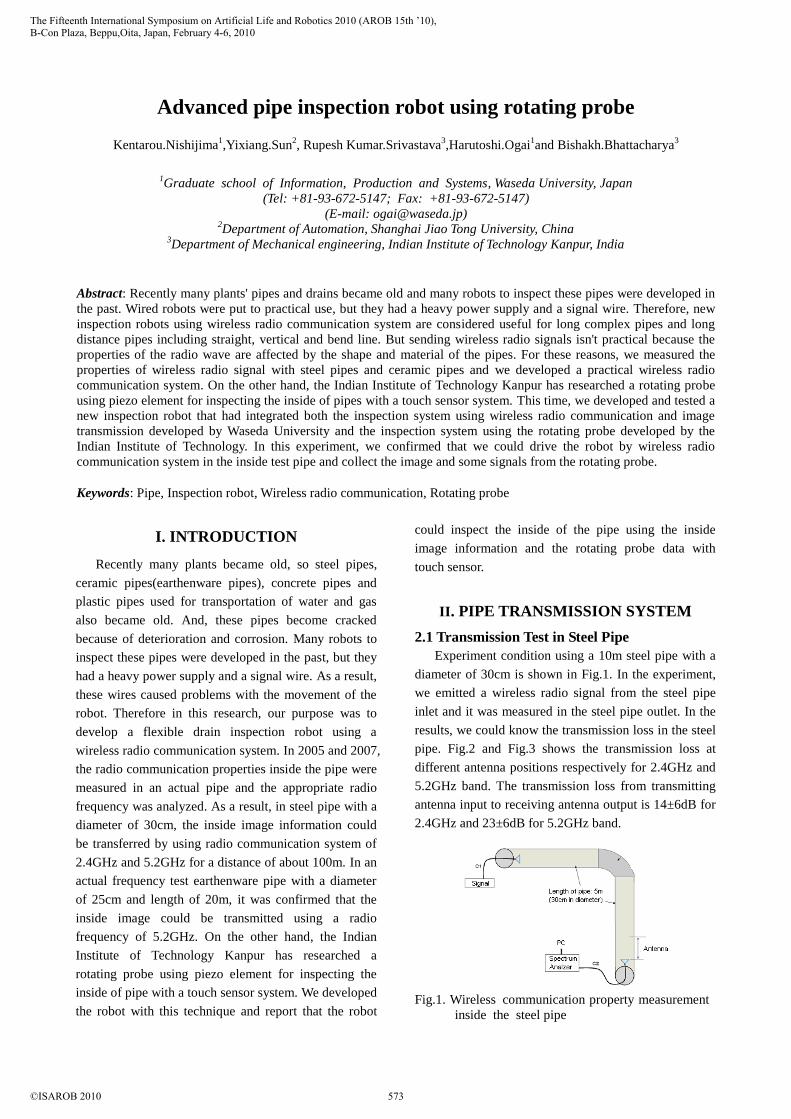
2.1 Transmission Test in Steel Pipe
Experiment condition using a 10m steel pipe with a
diameter of 30cm is shown in Fig.1. In the experiment,
we emitted a wireless radio signal from the steel pipe
inlet and it was measured in the steel pipe outlet. In the
results, we could know the transmission loss in the steel
pipe. Fig.2 and Fig.3 shows the transmission loss at
different antenna positions respectively for 2.4GHz and
5.2GHz band. The transmission loss from transmitting
antenna input to receiving antenna output is 14±6dB for
2.4GHz and 23±6dB for 5.2GHz band.
Fig.1. Wireless communication property measurement
inside the steel pipe
The Fifteenth International Symposium on Artificial Life and Robotics 2010 (AROB 15th ’10),B-Con Plaza, Beppu,Oita, Japan, February 4-6, 2010
©ISAROB 2010 573
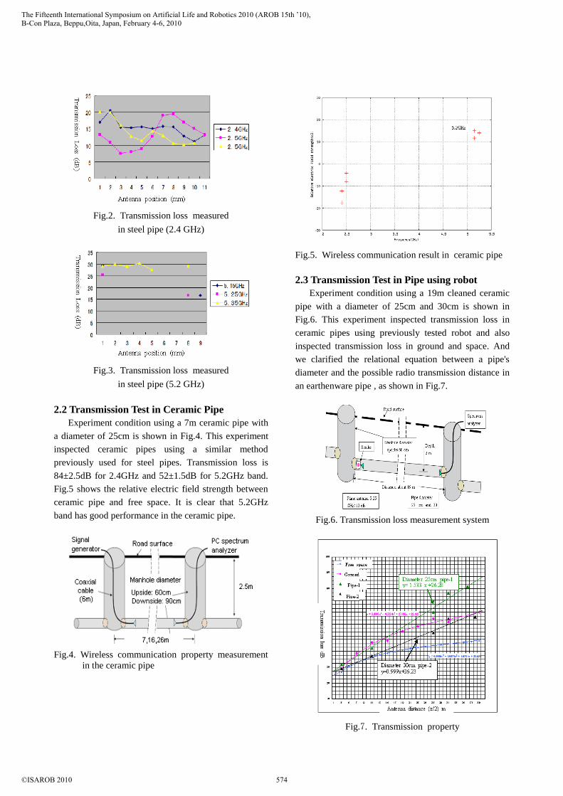
Fig.2. Transmission loss measured
in steel pipe (2.4 GHz)
Fig.3. Transmission loss measured
in steel pipe (5.2 GHz)
2.2 Transmission Test in Ceramic Pipe
Experiment condition using a 7m ceramic pipe with
a diameter of 25cm is shown in Fig.4. This experiment
inspected ceramic pipes using a similar method
previously used for steel pipes. Transmission loss is
84±2.5dB for 2.4GHz and 52±1.5dB for 5.2GHz band.
Fig.5 shows the relative electric field strength between
ceramic pipe and free space. It is clear that 5.2GHz
band has good performance in the ceramic pipe.
Fig.4. Wireless communication property measurement
in the ceramic pipe
Fig.5. Wireless communication result in ceramic pipe
2.3 Transmission Test in Pipe using robot Experiment condition using a 19m cleaned ceramic
pipe with a diameter of 25cm and 30cm is shown in
Fig.6. This experiment inspected transmission loss in
ceramic pipes using previously tested robot and also
inspected transmission loss in ground and space. And
we clarified the relational equation between a pipe's
diameter and the possible radio transmission distance in
an earthenware pipe , as shown in Fig.7.
Fig.6. Transmission loss measurement system
Fig.7. Transmission property
The Fifteenth International Symposium on Artificial Life and Robotics 2010 (AROB 15th ’10),B-Con Plaza, Beppu,Oita, Japan, February 4-6, 2010
©ISAROB 2010 574
III. DEVELOPMENT OF ADVANCED
INSPECTION ROBOT
From these results, we developed a drain pipe
inspection robot equipped with practical wireless radio
communication system. The robot was developed based
on drain pipe inspection robot 'Mogurinko250' by
Ishikawa Tekkousyo, as shown in Fig.8. This robot can
be controlled by wireless radio communication in the
inside pipe and can also transmit image information of
the inside of the pipe in real time.
Specifications of this inspection robot:
・ Size: length 370mm, width 180mm, height
160mm.
・ Moving speed: 13.7m/min,
・ Driving mode: double motor,
・ Electric Power: rechargeable batteries 7.2V.
・ Wireless frequency: apply to 2.4/5 GHz and
Data transmission by 100 base-T Ethernet.
・ USB Camera(300 thousand pixel)
Fig.8. Inspection robot (Mogurinko)
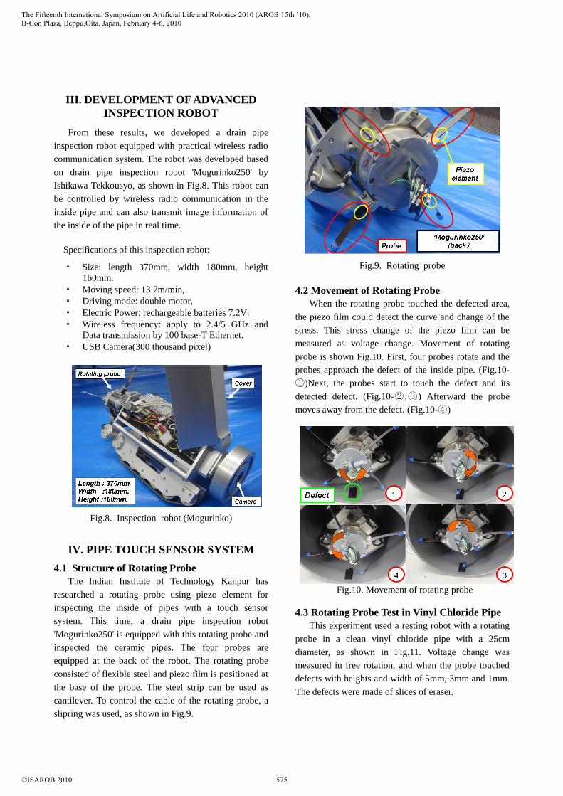
IV. PIPE TOUCH SENSOR SYSTEM
4.1 Structure of Rotating Probe
The Indian Institute of Technology Kanpur has
researched a rotating probe using piezo element for
inspecting the inside of pipes with a touch sensor
system. This time, a drain pipe inspection robot
'Mogurinko250' is equipped with this rotating probe and
inspected the ceramic pipes. The four probes are
equipped at the back of the robot. The rotating probe
consisted of flexible steel and piezo film is positioned at
the base of the probe. The steel strip can be used as
cantilever. To control the cable of the rotating probe, a
slipring was used, as shown in Fig.9.
Fig.9. Rotating probe
4.2 Movement of Rotating Probe
When the rotating probe touched the defected area,
the piezo film could detect the curve and change of the
stress. This stress change of the piezo film can be
measured as voltage change. Movement of rotating
probe is shown Fig.10. First, four probes rotate and the
probes approach the defect of the inside pipe. (Fig.10-
①)Next, the probes start to touch the defect and its
detected defect. (Fig.10-② ,③) Afterward the probe
moves away from the defect. (Fig.10-④)
Fig.10. Movement of rotating probe
4.3 Rotating Probe Test in Vinyl Chloride Pipe
This experiment used a resting robot with a rotating
probe in a clean vinyl chloride pipe with a 25cm
diameter, as shown in Fig.11. Voltage change was
measured in free rotation, and when the probe touched
defects with heights and width of 5mm, 3mm and 1mm.
The defects were made of slices of eraser.
The Fifteenth International Symposium on Artificial Life and Robotics 2010 (AROB 15th ’10),B-Con Plaza, Beppu,Oita, Japan, February 4-6, 2010
©ISAROB 2010 575
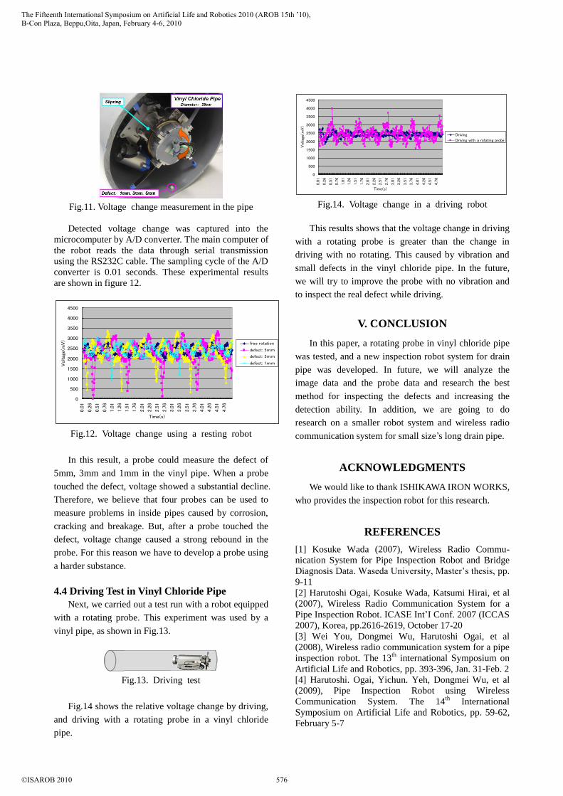
Fig.11. Voltage change measurement in the pipe
Detected voltage change was captured into the
microcomputer by A/D converter. The main computer of
the robot reads the data through serial transmission
using the RS232C cable. The sampling cycle of the A/D
converter is 0.01 seconds. These experimental results
are shown in figure 12.
0
500
1000
1500
2000
2500
3000
3500
4000
4500
0.0
1
0.2
6
0.5
1
0.7
6
1.0
1
1.2
6
1.5
1
1.7
6
2.0
1
2.2
6
2.5
1
2.7
6
3.0
1
3.2
6
3.5
1
3.7
6
4.0
1
4.2
6
4.5
1
4.7
6
Time(s)
Voltag
e(m
V)
free rotation
defect: 5mm
defect: 3mm
defect: 1mm
Fig.12. Voltage change using a resting robot
In this result, a probe could measure the defect of
5mm, 3mm and 1mm in the vinyl pipe. When a probe
touched the defect, voltage showed a substantial decline.
Therefore, we believe that four probes can be used to
measure problems in inside pipes caused by corrosion,
cracking and breakage. But, after a probe touched the
defect, voltage change caused a strong rebound in the
probe. For this reason we have to develop a probe using
a harder substance.
4.4 Driving Test in Vinyl Chloride Pipe
Next, we carried out a test run with a robot equipped
with a rotating probe. This experiment was used by a
vinyl pipe, as shown in Fig.13.
Fig.13. Driving test
Fig.14 shows the relative voltage change by driving,
and driving with a rotating probe in a vinyl chloride
pipe.
0
500
1000
1500
2000
2500
3000
3500
4000
4500
0.0
1
0.2
6
0.5
1
0.7
6
1.0
1
1.2
6
1.5
1
1.7
6
2.0
1
2.2
6
2.5
1
2.7
6
3.0
1
3.2
6
3.5
1
3.7
6
4.0
1
4.2
6
4.5
1
4.7
6
Time(s)
Voltag
e(m
V)
Driving
Driving with a rotating probe
Fig.14. Voltage change in a driving robot
This results shows that the voltage change in driving
with a rotating probe is greater than the change in
driving with no rotating. This caused by vibration and
small defects in the vinyl chloride pipe. In the future,
we will try to improve the probe with no vibration and
to inspect the real defect while driving.
V. CONCLUSION
In this paper, a rotating probe in vinyl chloride pipe
was tested, and a new inspection robot system for drain
pipe was developed. In future, we will analyze the
image data and the probe data and research the best
method for inspecting the defects and increasing the
detection ability. In addition, we are going to do
research on a smaller robot system and wireless radio
communication system for small size’s long drain pipe.
ACKNOWLEDGMENTS
We would like to thank ISHIKAWA IRON WORKS,
who provides the inspection robot for this research.
REFERENCES
[1] Kosuke Wada (2007), Wireless Radio Commu-
nication System for Pipe Inspection Robot and Bridge
Diagnosis Data. Waseda University, Master’s thesis, pp.
9-11
[2] Harutoshi Ogai, Kosuke Wada, Katsumi Hirai, et al
(2007), Wireless Radio Communication System for a
Pipe Inspection Robot. ICASE Int’I Conf. 2007 (ICCAS
2007), Korea, pp.2616-2619, October 17-20
[3] Wei You, Dongmei Wu, Harutoshi Ogai, et al
(2008), Wireless radio communication system for a pipe
inspection robot. The 13th
international Symposium on
Artificial Life and Robotics, pp. 393-396, Jan. 31-Feb. 2
[4] Harutoshi. Ogai, Yichun. Yeh, Dongmei Wu, et al
(2009), Pipe Inspection Robot using Wireless
Communication System. The 14th
International
Symposium on Artificial Life and Robotics, pp. 59-62,
February 5-7
The Fifteenth International Symposium on Artificial Life and Robotics 2010 (AROB 15th ’10),B-Con Plaza, Beppu,Oita, Japan, February 4-6, 2010
©ISAROB 2010 576