Embed Size (px)
Citation preview

Form No. S3208-607Supersedes S3208-206Page 1 of 12
THE WALL-MOUNT™ AIR CONDITIONERS - WA (60HZ)
Aluminum Finned Copper Coils:
Grooved tubing and enhanced louvered
fin for maximum heat transfer and
energy efficiency.
Twin Blowers:
Move air quietly. Most models feature
multispeed blower motors providing
airflow adjustment for high and low
static operation. Motor overload
protection is standard on all models.
Air Conditioner Compressor:
Reciprocating compressors with
crankcase heater and dual discharge
muffler are standard on 1.5 and 2 ton
models.
Scroll Compressors eliminate need for
crankcase heater. Standard on 2.5 to
5 ton, and available on 2 ton models.
Phase Rotation Monitor:
Standard on all 3 phase scroll
compressors. Protects against reverse
rotation if power supply is not properly
connected. Not required on
reciprocating compressors.
Galvanized 20 Gauge Zinc Coated
Steel Cabinet:
Cleaned, rinsed, sealed and dried
before the polyurethane primer is
applied. The cabinet is handsomely
finished with a baked on textured
enamel, which allows it to withstand
1000 hours of salt spray tests per
ASTM B117-03.
Electrical Components:
Are easily accessible for routine
inspection and maintenance through a
right side, service panel opening.
Features a lockable, hinged access
cover to the circuit breaker or pull
disconnect switch.
Electric Heat Strips:
Features an automatic limit and thermal
cut-off safety control. Heater packages
can be factory or field installed for all 1.5
through 5 ton models.
One Inch, Disposable Air Filters:
Are standard equipment. Optional one
inch washable filters available and filter
racks permit the addition of 2" pleated
filter. Factory or field installed.
Condenser Fan and Motor
Shroud Assembly:
Slides out for easy access.
Barometric Fresh Air Damper:
Standard on all units. Allows up to 25%
outside fresh air.
Built-in Circuit Breakers:
Standard on all electric heat versions of
single (230/208 volt) and three phase
(230/208 volt) equipment. Toggle
disconnects are standard on all electric
heat versions of three phase (460 volt)
equipment.
Slope Top:
Standard feature for water run-off.
Full Length Mounting Brackets:
Built into cabinet for improved
appearance and easy installation.
NOTE: Bottom mounting bracket
included to assist in installation.
Top Rain Flashing:
Standard feature on all models.
All packages are
designed to meet your
specific ventilation
requirements utilizing one
of five ventilation
options for the product.
The ventilation package is
mounted within the unit
eliminating the need for
an exterior mounted hood
or damper assembly on
the unit. All assemblies
can be factory installed,
installed in the field at
time of installation or as a
retrofit system after
installation.
� Standard - Barometric
Fresh Air Damper
� Optional - Motorized
Fresh Air Damper
� Optional - Blank off
Plate
� Optional - Commercial
Room Ventilator w/Exhaust
• CRV - Spring Return
• CRVP - Power Return
� Optional - Economizer w/
Exhaust
� Optional - Energy
Recovery Ventilator
Engineered Features
The Bard Wall-Mount Air Conditioner is a self contained energy efficient
system, which is designed to offer maximum indoor comfort at a minimal
cost without using valuable indoor floor space or outside ground space.
This unit is the ideal product for versatile applications such as: new
construction, modular offices, school modernization, telecommunication
structures, portable structures or correctional facilities. Factory or field
installed accessories are available to meet specific job requirements.
Ventilation System Packages
WA-SERIES Refrigerant 22 60Hz 1.5 to 5 Ton (18,300 to 57,500 Btuh) Right Side Control Panel
•Complies with efficiency requirements of ASHRAE/IESNA 90.1-2004.
•Certified to ANSI/ARI Standard 390-2003 for SPVU (Single Package Vertical Units).
•Commercial Product - Not intended for Residential application.
MEA # 357-93-E

Form No. S3208-607Supersedes S3208-206Page 12 of 12
*Optional top outlet (factory installed only) for WA30 and WA37 models only.
Bard Manufacturing Company, Inc.
Bryan, Ohio 43506
www.bardhvac.com
Since 1914 . . . Moving ahead,
just as planned
Due to our continuous product improvement policy,
all specifications subject to change without notice.
Before purchasing this appliance, read important energy cost
and efficiency information available from your retailer.
All dimensions are in inches. Dimensional drawings are not to scale.
NOTE: For side by side installation of two (2) WA models there
must be 20" between units. This can be reduced to 15" by using a
WL model (left side compressor and controls) for the left unit and
WA (right side compressor and controls) for right unit.
See WL Specifications S3279.
1 Refer to the Installation Manual for more detailed information.
sseccAecivreSrofderiuqeRsecnaraelCwolFriAresnednoCetauqedAdna
SLEDOM EDISTFEL EDISTHGIR
73AW,52AW,42AW,81AW "51 "02
06AW,84AW,24AW "02 "02
otderiuqeRsecnaraelCmuminiMslairetaMelbitsubmoC
SLEDOM 1TCUDRIAYLPPUSTEEFEERHTTSRIF
TENIBAC
52AW,42AW,81AW "0 "0
73AW,03AW "4/1 "0
06AW,84AW,24AW "4/1 "0
)lanimoN(stnemeriuqeRnoitallatsnIdnalarutcetihcrAroftinUcisaBfosnoisnemiD
LEDOMHTDIW
)W(HTPED
)D(THGIEH
)H(YLPPUS NRUTER
A B C B E F G I J K L M N O P Q R S T81AW42AW52AW
003.33 521.71 365.07 88.7 88.91 88.11 88.91 00.53 05.81 57.52 65.02 57.62 60.82 52.92 00.72 36.2 31.43 60.22 55.01 91.4 00.21 00.5
03AW73AW
002.83 521.71 365.07 88.7 88.72 88.31 88.72 00.04 05.81 57.52 39.71 57.62 57.82 52.92 00.72 57.2 91.93 57.22 41.9 91.4 00.21 00.5
24AW84AW06AW
570.24 234.22 578.48 88.9 88.92 88.51 88.92 88.34 01.91 66.13 00.03 86.23 49.62 96.43 34.23 73.3 88.24 88.32 00.01 00.2 00.61 88.1
SIDE VIEW BACK VIEWFRONT VIEW
Form No.
S3208
June, 2007
Supersedes S3208-206

Form No. S3208-607Supersedes S3208-206Page 2 of 12
SLEDOM A-281AW A-242AW B-242AW C-242AW A-352AW B-352AW A-203AW B-203AW C-203AW A-273AW B-273AW C-273AW
zH06--gnitaRlacirtcelE 1-802/032 1-802/032 3-802/032 3-064 1-802/032 3-802/032 1-802/032 3-802/032 3-064 1-802/032 3-802/032 3-064
egnaRegatloVgnitarepO 352-791 352-791 352-791 605-414 352-791 352-791 352-791 352-791 605-414 352-791 352-791 605-414
AtiucriC--rosserpmoC
egatloV 802/032 802/032 802/032 064 802/032 802/032 802/032 802/032 064 802/032 802/032 064
spmAdaoLdetaR 0.8/0.7 0.01/5.9 9.6/6.6 6.3 5.9/6.8 0.7/5.6 9.21/2.21 4.8/4.8 2.4 3.71/5.61 0.11/5.01 2.5
tiucriChcnarBtnerruCnoitceleS
0.9 0.01 0.7 0.4 3.01 1.7 1.41 0.9 5.4 3.71 0.11 5.5
spmArotoRkcoL 94/94 65/65 15/15 52 45/45 54/54 37/37 36/36 13 001/001 77/77 73
epyTrosserpmoC .piceR .piceR .piceR .piceR llorcS llorcS llorcS llorcS llorcS llorcS llorcS llorcS
resnednoC&rotoMnaF
MPR--PH--rotoMnaF 5701-5/1 5701-5/1 5701-5/1 5701-5/1 5701-5/1 5701-5/1 5701-5/1 5701-5/1 5701-5/1 5701-5/1 5701-5/1 5701-5/1
spmA--rotoMnaF 2.1 2.1 2.1 4.1 2.1 2.1 5.1 5.1 4.1 5.1 5.1 4.1
MFC/AID--naF 0061-"81 0061-"81 0061-"81 0061-"81 0061-"81 0061-"81 0012-"02 0012-"02 0012-"02 0091-"02 0091-"02 0091-"02
.pavE&rotoMrewolB
DPS-MPR-PH--rotoMrewolB 1-0011-6/1 1-0011-6/1 1-0011-6/1 2-0011-3/1 1-0011-6/1 1-0011-6/1 2-0011-3/1 2-0011-3/1 2-0011-3/1 2-0011-3/1 2-0011-3/1 2-0011-3/1
spmA--rotoMrewolB 0.1 0.1 0.1 1.1 0.1 0.1 2.2 2.2 1.1 2.2 2.2 1.1
.P.S.E&gnilooCMFC)lioCteW-detaR(retliF/w
04.-056 02.-008 02.-008 02.-008 02.-008 02.-008 04.-0001 04.-0001 04.-0001 03.-0011 03.-0011 03.-0011
.DTS)sehcni(seziSretliF 1x52x61 1x52x61 1x52x61 1x52x61 1x52x61 1x52x61 1x03x61 1x03x61 1x03x61 1x03x61 1x03x61 1x03x61
.SBL--thgieWgnippihS 003 003 003 003 003 003 553 553 553 553 553 553
SLEDOM 281AW 242AW 352AW 203AW 273AW 324AW 484AW 206AW
HUTByticapaCgnilooC 1 003,81 004,32 000,32 000,03 000,63 000,24 005,74 005,75
REE 2 02.9 02.9 08.9 03.9 02.9 02.9 06.9 07.8
REES 3 02.01 05.01 00.11 06.01 00.01 06.01 00.11 02.01
Capacity and Efficiency Ratings
Specifications 1-1/2 Ton through 3 Ton
SLEDOM A-324AW B-324AW C-324AW A-484AW B-484AW C-484AW A-206AW B-206AW C-206AW
zH06--gnitaRlacirtcelE 1-802/032 3-802/032 3-064 1-802/032 3-802/032 3-064 1-802/032 3-802/032 3-064
egnaRegatloVgnitarepO 352-791 352-791 605-414 352-791 352-791 605-414 352-791 352-791 605-414
AtiucriC--rosserpmoC
egatloV 802/032 802/032 064 802/032 802/032 064 802/032 802/032 064
spmAdaoLdetaR 12/3.91 8.11/8.11 1.6 8.02/2.02 3.21/9.11 2.6 5.82/0.62 4.81/1.81 8.6
tiucriChcnarBtnerruCnoitceleS
12 5.21 5.6 8.12 9.21 5.6 0.92 0.91 0.9
spmArotoRkcoL 721/721 88/88 24 131/131 19/19 64 841/841 731/731 26
epyTrosserpmoC llorcS llorcS llorcS llorcS llorcS llorcS llorcS llorcS llorcS
resnednoC&rotoMnaF
DPS-MPR-PH--rotoMnaF 2-058-3/1 2-058-3/1 2-058-3/1 2-058-3/1 2-058-3/1 2-058-3/1 2-058-3/1 2-058-3/1 2-058-3/1
spmA--rotoMnaF 5.2 5.2 3.1 5.2 5.2 3.1 5.2 5.2 3.1
MFC/AID--naF 0062-"42 0062-"42 0062-"42 0062-"42 0062-"42 0062-"42 0062-"42 0062-"42 0062-"42
.pavE&rotoMrewolB
DPS-MPR-PH--rotoMrewolB 2-0701-2/1 2-0701-2/1 2-0701-2/1 2-0701-2/1 2-0701-2/1 2-0701-2/1 2-0701-2/1 2-0701-2/1 2-0701-2/1
spmA--rotoMrewolB 3.3 3.3 9.1 3.3 3.3 9.1 3.3 3.3 9.1
.P.S.E&gnilooCMFC)lioCteW-detaR(retliF/w
03.-0041 03.-0041 03.-0041 02.-0551 02.-0551 02.-0551 03.-0071 03.-0071 03.-0071
.DTS)sehcni(seziSretliF 1x03x02 1x03x02 1x03x02 1x03x02 1x03x02 1x03x02 1x03x02 1x03x02 1x03x02
.SBL--thgieWgnippihS 005 005 005 005 005 005 005 005 005
Specifications 3-1/2 Ton through 5 Ton
1 Capacity is certified in accordance with ANSI/ARI Standard 390-2003 and tested in accordance with ARI Standard 210/240-2006.
2 EER = Energy Efficiency Ratio and is certified in accordance with ANSI/ARI Standard 390-2003.
3 SEER = Seasonal Energy Efficiency Ratio and is tested in accordance with ARI Standard 210/240-2006.
All ratings based on fresh air intake being 100% closed (no outside air introduction).

Form No. S3208-607Supersedes S3208-206Page 3 of 12
Bard Wall-Mounts are designed to provide optional ventilation packages to meet all of your ventilation and indoor air quality requirements. All
units are equipped with a barometric fresh air damper as the standard ventilation package. All ventilation packages can be built-in at the
factory or field-installed at a later date.
Manufactured under U.S. Patent Nos. 5,485,878; 5,301,744;
5,002,116; 4,924,934; 4,875,520; 4,825,936; 6,310,330.
Barometric Fresh Air Damper
Motorized Fresh Air Damper
Commercial Room Ventilator
Economizer
Energy Recovery Ventilator
BAROMETRIC FRESH AIR DAMPER - BFAD STANDARD
The barometric fresh air damper is a standard feature on all models. It is installed on the inside of the service
door and allows outside ventilation air, up to 25% of the total airflow rating of the unit, to be introduced through the
air inlet openings and to be mixed with the conditioned air. The damper opens during blower operation and
closes when the blower is off. Adjustable blade stops allow different amounts of outside air to be introduced into
the building and can be easily locked closed if required.
BLANK OFF PLATE - BOP OPTIONALA blank off plate is installed on the inside of the service door. It covers the air inlet openings, which restricts any
outside air from entering the unit. The blank off plate should be utilized in applications where outside air is not
required to be mixed with the conditioned air.
MOTORIZED FRESH AIR DAMPER - MFAD OPTIONALThe motorized fresh air damper is internally mounted behind the service door and allows outside ventilation air,
up to 25% of the total airflow rating of the unit, to be introduced through the air inlet openings and to be mixed
with the conditioned air. The two position damper can be fully open or closed. The damper blade is powered
open by a 24VAC motor with spring return on power loss. The damper can be controlled by indoor blower
operation or can be field connected to be managed based on building occupancy.
COMMERCIAL ROOM VENTILATOR - CRV OPTIONALThe built-in commercial room ventilator is internally mounted behind the service door and allows outside
ventilation air, up to 50% of the total airflow rating of the unit, to be introduced through the air inlet openings.
It includes a built-in exhaust air damper.
The commercial room ventilator (CRV) is a simple and innovative approach to improving the indoor air quality by
providing fresh air intake and exhaust capability through the CRV. The damper can be easily adjusted to control the
amount of fresh air supplied into the building. The CRV can be controlled by indoor blower operation or field controlled
based on room occupancy. Two versions available (except on 1.5 and 2-Ton models). The CRV and CRVS are
power open - spring return on power loss, and CRVP is power open and power close. Complies with ANSI/ASHRAE
Standard 62.1 “Ventilation for Acceptable Indoor Air Quality”.
ECONOMIZER - EIFM OPTIONALThe built-in economizer system is internally mounted behind the service door and allows outdoor air to be
introduced through the air inlet openings. The amount of outdoor air varies in response to the system controls and
settings defined by the end user. It includes a built-in exhaust air damper. The economizer is designed to provide
“free cooling” when outside air conditions are cool and dry enough to satisfy cooling requirements without running
the compressor. This in turn provides lower operating costs, while extending the life of the compressor.
Standard Features:
• One Piece Construction - Easy to install with no mechanical linkage adjustment required.
• Exhaust Air Damper - Built in with positive closed position. Provides exhaust air capability to prevent
pressurization of tight buildings.
• Actuator Motor - 24 volt, power open, spring return with built in torque limiting switch.
• Proportioning Type Control - for maximum “free cooling” economy and comfort.
• Moisture Eliminator & Prefilter - permanent, washable aluminum construction.
• Enthalpy Control - adjustable to monitor outdoor temperature and humidity.
• Minimum Position Potentiometer - adjustable to control minimum damper blade position for ventilation
purposes.
• Mixed Air Sensor - to monitor outside and return air to automatically modulate damper position.
WALL-MOUNT ENERGY RECOVERY VENTILATOR - WERV OPTIONALThe wall-mount energy recovery ventilator (WERV) is a highly innovative approach to meeting indoor air quality
ventilation requirements as established by ANSI/ASHRAE Standard 62.1. The WERV allows from 200 to 450
CFM (depending upon model) of fresh air and exhaust through the unit while maintaining superior indoor comfort
and humidity levels. In most cases this can be accomplished without increasing equipment sizing or operating
costs. Heat transfer efficiency is up to 67% during summer and 75% during winter conditions.
The WERV consists of a unique “rotary energy recovery cassette” that provides effective sensible and latent heat
transfer capabilities during summer and winter conditions. Various control schemes are addressed including
limiting ventilation during building occupancy only.
The WERV is designed to be internally mounted behind the service door in the WA, WH or WL model wall-mount
units. It can be built-in at the factory or field installed as an option. WERV-*3C and WERV-*5C can be
independently adjusted for intake and exhaust rates.
Ventilation System Packages
NOTE: The above vent systems are intake only without built-in exhaust capability. Building will likely require
separate field installed barometric relief or mechanical exhaust elsewhere within the conditioned space. Balancing
dampers in the return air grille may be required to achieve specified amount of outdoor air intake.

Form No. S3208-607Supersedes S3208-206Page 4 of 12
WA
18
, W
A2
4 &
WA
25
TO
TA
L A
ND
VE
NT
ILA
TIO
N A
IRF
LO
W
0
100
200
300
400
500
600
700
800
900
10
00
11
00
AB
CD
EF
Ve
nt
Po
sit
ion
Airflow (cfm)
Tota
l A
ir 0
ES
P
Tota
l A
ir .
15
ES
P
Tota
l A
ir .
3 E
SP
Ve
nt
Air
0 E
SP
Ve
nt
Air
.1
5 E
SP
Ve
nt
Air
.3
ES
P
Co
mm
erc
ial
Ro
om
Ven
tila
tor
Perf
orm
an
ce D
ata
- C
RV
S-3
an
d C
RV
P-3
Co
mm
erc
ial
Ro
om
Ven
tila
tor
Perf
orm
an
ce D
ata
- C
RV
-2
WA
30
& W
A3
7 H
IGH
SP
EE
D T
OT
AL
AN
D V
EN
TIL
AT
ION
AIR
FL
OW
0
100
200
300
400
500
600
700
800
900
1000
1100
1200
AB
CD
EF
Ven
t P
osit
ion
Airflow (cfm)
To
tal A
ir 0
ES
P
To
tal A
ir .1
5 E
SP
To
tal A
ir .3
ES
P
Ven
t A
ir 0
ES
P
Ven
t A
ir .15 E
SP
Ven
t A
ir .3 E
SP
WA
30
& W
A3
7 L
OW
SP
EE
D T
OT
AL
AN
D V
EN
TIL
AT
ION
AIR
FL
OW
0
10
0
20
0
30
0
40
0
50
0
60
0
70
0
80
0
90
0
10
00
AB
CD
EF
Ve
nt
Po
sit
ion
Airflow (cfm)T
ota
l A
ir 0
ES
P
To
tal A
ir .
15
ES
P
To
tal A
ir .
3 E
SP
Ve
nt
Air
0 E
SP
Ve
nt
Air
.1
5 E
SP
Ve
nt
Air
.3
ES
P

Form No. S3208-607Supersedes S3208-206Page 5 of 12
Co
mm
ercia
l R
oo
m V
en
tila
tor P
erfo
rm
an
ce D
ata
- C
RV
S-5
an
d C
RV
P-5
Co
mm
ercia
l R
oo
m V
en
tila
tor P
erfo
rm
an
ce D
ata
- C
RV
S-5
an
d C
RV
P-5
WA
42
& W
A4
8 H
IGH
SP
EE
D T
OT
AL
AN
D V
EN
TIL
AT
ION
AIR
FL
OW
0
100
200
300
400
500
600
700
800
900
10
00
11
00
12
00
13
00
14
00
15
00
16
00
17
00
18
00
19
00
20
00
21
00
AB
CD
EF
Ven
t P
os
itio
n
Airflow (cfm)
Tota
l A
ir 0
ES
P
Tota
l A
ir .
2 E
SP
Tota
l A
ir .
4 E
SP
Ve
nt A
ir 0
ES
P
Ve
nt A
ir .2
ES
P
Ve
nt A
ir .4
ES
P
WA
42
& W
A4
8 L
OW
SP
EE
D T
OT
AL
AN
D V
EN
TIL
AT
ION
AIR
FL
OW
0
10
0
20
0
30
0
40
0
50
0
60
0
70
0
80
0
90
0
10
00
11
00
12
00
13
00
14
00
15
00
16
00
17
00
AB
CD
EF
Ve
nt
Po
sit
ion
Airflow (cfm)
Tota
l A
ir 0
ES
P
Tota
l A
ir .2
ES
P
Tota
l A
ir .4
ES
P
Ve
nt A
ir 0
ES
P
Ve
nt A
ir .
2 E
SP
Ve
nt A
ir .
4 E
SP
WA
60
HIG
H S
PE
ED
TO
TA
L A
ND
VE
NT
ILA
TIO
N A
IRF
LO
W
0
100
200
300
400
500
600
700
800
900
10
00
11
00
12
00
13
00
14
00
15
00
16
00
17
00
18
00
19
00
20
00
21
00
22
00
AB
CD
EF
Ve
nt
Po
sit
ion
Airflow (cfm)
Tota
l A
ir 0
ES
P
Tota
l A
ir .
2 E
SP
Tota
l A
ir .
4 E
SP
Ven
t A
ir 0
ES
P
Ven
t A
ir .2
ES
P
Ven
t A
ir .4
ES
P
0
100
200
300
400
500
600
700
800
900
1000
1100
1200
1300
1400
1500
1600
AB
CD
EF
Ven
t P
osit
ion
Airflow (cfm)
Tota
l A
ir 0
ES
P
Tota
l A
ir .
2 E
SP
Tota
l A
ir .
4 E
SP
Vent
Air 0
ES
P
Vent
Air .
2 E
SP
Vent
Air .
4 E
SP
WA
60
LO
W S
PE
ED
TO
TA
L A
ND
VE
NT
ILA
TIO
N A
IRF
LO
W

Form No. S3208-607Supersedes S3208-206Page 6 of 12
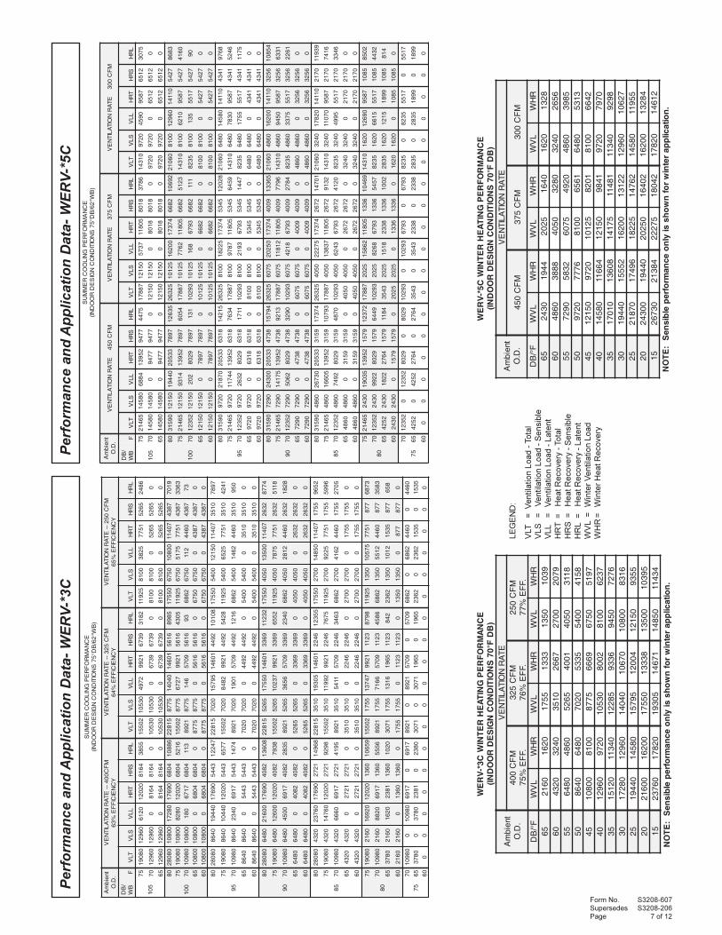
LEGEND:
VLT = Ventilation Load - Total
VLS = Ventilation Load - Sensible
VLL = Ventilation Load - Latent
HRT = Heat Recovery - Total
HRS = Heat Recovery - Sensible
HRL = Heat Recovery - Latent
WVL = Winter Ventilation Load
WHR= Winter Heat Recovery
Performance and Application Data- WERV-*2B
ECNAMROFREPGNITAEHRETNIWB2*-VREW)BDF°07SNOITIDNOCNGISEDROODNI(
tneibmA.D.O
ETARNOITALITNEVMFC052
.FFE%47MFC522
.FFE%57MFC002
.FFE%57F°/BD LVW RHW LVW RHW LVW RHW
56 0531 999 4121 119 0801 01806 0072 8991 9242 2281 0612 026155 0504 7992 3463 3372 0423 034205 0045 6993 8584 3463 0234 042354 0576 5994 2706 4554 0045 050404 0018 4995 7827 5645 0846 068453 0549 3996 1058 6736 0657 076503 00801 2997 6179 7827 0468 084652 05121 1998 03901 8918 0279 092702 00531 0999 54121 8019 00801 001851 05841 98901 95331 91001 08811 0198
.noitacilpparetniwrofnwohssiylnoecnamrofrepelbisneS:ETON
ECNAMROFREPGNILOOCREMMUS)BW°26/BD°57SNOITIDNOCNGISEDROODNI(
tneibmA.D.O
MFC052--ETARNOITALITNEVYCNEICIFFE%26
MFC522--ETARNOITALITNEVYCNEICIFFE%36
MFC002--ETARNOITALITNEVYCNEICIFFE%36
/BDBW F TLV SLV LLV TRH SRH LRH TLV SLV LLV TRH SRH LRH TLV SLV LLV TRH SRH LRH
501
57 52911 0018 5231 4937 2205 228 72701 7827 1443 8576 1954 8612 0459 0846 0603 0106 2804 8291
07 0018 0018 0 2205 2205 0 7827 7827 0 1954 1954 0 0846 0846 0 2804 2804 0
56 0018 0018 0 2205 2205 0 7827 7827 0 1954 1954 0 0846 0846 0 2804 2804 0
001
08 05571 0576 00801 18801 5814 6966 88751 2706 6179 6499 6283 1216 04041 0045 0468 5488 2043 3445
57 52911 0576 5715 4937 5814 9023 72701 2706 5564 8576 6283 3392 0459 0045 0414 0106 2043 8062
07 3686 0576 311 5524 5814 07 3716 2706 101 9883 6283 46 0945 0045 09 8543 2043 65
56 0576 0576 0 5814 5814 0 2706 2706 0 6283 6283 0 0045 0045 0 2043 2043 0
06 0576 0576 0 5814 5814 0 2706 2706 0 6283 6283 0 0045 0045 0 2043 2043 0
59
08 05571 0045 05121 18801 8433 3357 88751 8584 03901 6499 0603 6886 04041 0234 0279 5488 2272 4216
57 52911 0045 5256 4937 8433 6404 72701 8584 0785 8576 0603 8963 0459 0234 0225 0106 2272 9823
07 3686 0045 3641 5524 8433 709 3716 8584 5131 9883 0603 928 0945 0234 0711 8543 2272 737
56 0045 0045 0 8433 8433 0 8584 8584 0 0603 0603 0 0234 0234 0 2272 2272 0
06 0045 0045 0 8433 8433 0 8584 8584 0 0603 0603 0 0234 0234 0 2272 2272 0
09
08 05571 0504 00531 18801 1152 0738 88751 3463 54121 6499 5922 1567 04041 0423 00801 5488 1402 4086
57 52911 0504 5787 4937 1152 3884 72701 3463 4807 8576 5922 3644 0459 0423 0036 0106 1402 9693
07 3686 0504 3182 5524 1152 4471 3716 3463 0352 9883 5922 4951 0945 0423 0522 8543 1402 7141
56 0504 0504 0 1152 1152 0 3463 3463 0 5922 5922 0 0423 0423 0 1402 1402 0
06 0504 0504 0 1152 1152 0 3463 3463 0 5922 5922 0 0423 0423 0 1402 1402 0
58
08 05571 0072 05841 18801 4761 7029 88751 9242 95331 6499 0351 6148 04041 0612 08811 5488 1631 4847
57 52911 0072 5229 4937 4761 0275 72701 9242 8928 8576 0351 8225 0459 0612 0837 0106 1631 9464
07 3686 0072 3614 5524 4761 1852 3716 9242 4473 9883 0351 9532 0945 0612 0033 8543 1631 8902
56 0072 0072 0 4761 4761 0 9242 9242 0 0351 0351 0 0612 0612 0 1631 1631 0
06 0072 0072 0 4761 4761 0 9242 9242 0 0351 0351 0 0612 0612 0 1631 1631 0
08
57 52911 0531 57501 4937 738 7556 72701 4121 3159 8576 567 3995 0459 0801 0648 0106 086 0335
07 3686 0531 3155 5524 738 8143 3716 4121 9594 9883 567 4213 0945 0801 0144 8543 086 8772
56 3632 0531 3101 5641 738 826 5212 4121 119 9331 567 745 0981 0801 018 0911 086 015
06 0531 0531 0 738 738 0 4121 4121 0 567 567 0 0801 0801 0 086 086 0
57
07 3686 0 3686 5524 0 5524 3716 0 3716 9886 0 9883 0945 0 0945 8543 0 8543
56 3632 0 3632 5641 0 5641 5212 0 5212 9331 0 9331 0981 0 0981 0911 0 0911
06 0 0 0 0 0 0 0 0 0 0 0 0 0 0 0 0 0 0
Form No. S3208-607Supersedes S3208-206Page 7 of 12
LE
GE
ND
:
VLT
=
V
entila
tion L
oad -
Tota
l
VLS
=V
entila
tion L
oad -
Sensib
le
VLL
=V
entila
tion L
oad -
Late
nt
HR
T=
Heat R
ecovery
- T
ota
l
HR
S=
Heat R
ecovery
- S
ensib
le
HR
L =
Heat R
ecovery
- L
ate
nt
WV
L=
Win
ter
Ventila
tion L
oad
WH
R=
Win
ter
Heat R
ecovery
Perf
orm
an
ce a
nd
Ap
plicati
on
Data
- W
ER
V-*
5C
Perf
orm
an
ce a
nd
Ap
plicati
on
Data
- W
ER
V-*
3C
EC
NA
MR
OF
RE
PG
NILO
OC
RE
MM
US
)B
W°26/B
D°57S
NOITI
DN
OC
NGI
SE
DR
OO
DNI(
tneibm
A.
D.O
MF
C004--
ETA
RN
OITALIT
NE
VY
CN
EICI
FF
E%36
MF
C523
--ET
AR
NOIT
ALITN
EV
YC
NEI
CIF
FE
%46M
FC
052--
ETA
RN
OITALIT
NE
VY
CN
EICI
FF
E%56
/B
DB
WF
TLV
SLV
LLV
TR
HS
RH
LR
HTL
VSL
VLL
VT
RH
SR
HL
RH
TLV
SLV
LLV
TR
HS
RH
LR
H
501
5708091
069210216
020214618
558320551
035012794
12999376
281352911
00185283
15775625
6842
0706921
069210
46184618
003501
035010
93769376
00018
0 0180
56255625
0
5606921
069210
46184618
003501
035010
93769376
00018
00180
56255625
0
001
0808082
0080108271
096714086
6880151822
577804041
106416165
589805571
057600801
704117834
9107
5708091
008010828
020214086
612520551
57787276
12996165
503452911
05765715
15777834
3633
0708901
00801081
71764086
3111298
5778641
90756165
392686
0576211
06447834
37
5600801
008010
40864086
05778
57780
61656165
00576
05760
78347834
0
0600801
008010
40864086
05778
57780
61656165
00576
05760
78347834
0
59
0808082
046804491
096713445
7422151822
020759751
106412944
8010105571
004505121
704110153
7987
5708091
046804401
020213445
775620551
020728 48
12992944
824552911
00455256
15770153
1424
0708901
04680432
71963445
47411298
02071091
90752944
61212686
00452641
06440153
059
560468
04680
34453445
002 07
02070
29442944
00045
00450
01530153
0
060468
04680
34453445
00207
02070
29442944
00045
00450
01530153
0
09
0808082
084600612
096712804
8063151822
562505571
106419633
2321105571
050400531
704112362
4778
5708091
084600621
020212804
839720551
562573201
12999633
255652911
05045787
15772362
8115
0708901
08460054
71962804
53821298
56256563
90759633
04322686
05042182
06442362
8281
560846
08460
28042804
05625
56250
96339633
00504
05040
23622362
0
060846
08460
28042804
05625
56250
96339633
00504
05040
23622362
0
58
0808082
023406732
096711272
8694151822
015350391
106416422
5532105571
007205841
704115571
2569
5708091
023406741
020211272
892920551
015329 911
12996422
576752911
00725229
15775571
6995
0708901
02340666
71961272
59141298
01531145
90756422
36432686
00722614
06445571
5072
560234
02340
1272127 2
00153
01530
64226422
00072
00720
55715571
0
060234
02340
12721272
00153
01530
64226422
00072
00720
55715571
0
08
5708091
061202961
020210631
9560120551
557174731
12993211
897852911
053157501
1577778
3786
0708901
06120288
71960631
65551298
55716617
90753211
68542686
05312155
0644778
3853
560873
06120261
18320631
02011703
55716131
56913211
2482632
05312101
5351778
856
060612
06120
06310631
05571
55710
32113211
00531
05310
778778
0
57
0708901
008901
71960
71961298
01298
90750
90752686
02686
06440
0644
560873
00873
18320
08321703
01703
56910
56912632
02632
53510
5351
060
00
00
00
00
00
00
00
00
0
EC
NA
MR
OF
RE
PG
NILO
OC
RE
MM
US
)B
W°26/B
D°57S
NOITI
DN
OC
NGI
SE
DR
OO
DNI(
tneibm
A.
D.O
MF
C054
ETA
RN
OITALIT
NE
VM
FC
573ET
AR
NOIT
ALITN
EV
MF
C003
ETA
RN
OITALIT
NE
V
/B
DB
WF
TLV
SLV
LLV
TR
HS
RH
LR
HTL
VSL
VLL
VT
RH
SR
HL
RH
TLV
SLV
LLV
TR
HS
RH
LR
H
501
5756412
085414886
259317749
574478871
051217375
508118108
687301341
02790954
78592156
5703
0708541
085410
77497749
005121
051210
81088108
00279
02790
21562156
0
5608541
085410
77497749
005121
051210
81088108
00279
02790
21562156
0
001
0809513
0512104491
335027987
5362152362
5210100261
473712866
2960106012
001806921
011417245
3868
5756412
051214139
259317987
450678871
521012677
508112866
321501341
00180126
78597245
0614
0725321
05121202
92087987
13139201
52101861
39762866
1115328
0018531
71557245
09
5605121
051210
79877987
052101
521010
28662866
00018
00180
72457245
0
0605121
051210
79877987
052101
521010
28662866
00018
00180
72457245
0
59
0809513
027907812
335028136
5124152362
001852281
473715435
8202106012
084608541
011411434
8679
5756412
027944711
259318136
436778871
00187879
508115435
954601341
08460387
78591434
6425
0725321
02792362
92088136
117139201
00183912
39765435
74415328
08465571
71551434
5711
560279
02790
81368136
00018
00180
54355435
00846
08460
14341434
0
060279
02790
81368136
00018
00180
54355435
00846
08460
14341434
0
09
0809513
092700342
335028374
4975152362
570605202
473719004
5633106012
068400261
011416523
45801
5756412
092757141
259318374
312978871
570621811
508119004
697701341
06840549
78596523
1336
0725321
09272605
92088374
092339201
57068124
39769004
48725328
06845733
71556523
1622
560927
09270
83748374
05706
57060
90049004
00684
06840
65236523
0
060927
09270
83748374
05706
57060
90049004
00684
06840
65236523
0
58
0809513
068403762
335029513
4737152362
050457222
473712762
1074106012
042302871
011410712
93911
5756412
068450661
259319513
3970178871
050473831
508112762
231901341
042307011
78590712
6147
0725321
06842947
92089513
078439201
05043426
39762762
02145328
04235994
71550712
6433
560684
06840
95139513
00504
05040
27622762
00423
04230
07120712
0
060684
06840
95139513
00504
05040
27622762
00423
04230
07120712
0
08
5756412
034253091
259319751
2732178871
520226851
508116331
9640101341
026109621
78595801
2058
0725321
03422299
92089751
944639201
52028628
39766331
75455328
02615166
71555801
2344
562524
03422281
46729751
48113453
52028151
83326331
20015382
02615121
99815801
418
060342
03420
97519751
05202
52020
63316331
00261
02610
58015801
0
57
0725321
025321
92080
920839201
039201
39760
39765328
05328
71550
7155
562524
02524
46720
46723453
03453
83320
83325382
05382
99810
9981
060
00
00
00
00
00
00
00
00
0
EC
NA
MR
OF
RE
PG
NIT
AE
HR
ET
NIW
C3*-V
RE
W)
BD
F°07S
NOI
TID
NO
CN
GIS
ED
RO
OD
NI(
tneibm
A.
D.O
ETA
RN
OITALIT
NE
VM
FC
004.F
FE
%57M
FC
523.F
FE
%67M
FC
052.F
FE
%77F°/
BD
LV
WR
HW
LV
WR
HW
LV
WR
HW
560612
02615571
33310531
930106
02340423
01537662
00729702
550846
06845625
10040504
811305
04680846
02075335
00458514
5400801
00185778
96660576
791504
069210279
035012008
00187326
5302151
0431158221
63390549
672703
0827106921
0404107601
008016138
5204491
0854159751
4002105121
553902
0061200261
0557183331
0053159301
5106732
0287150391
1764105841
43411.
noitacil
ppa
retni
wr
ofn
wo
hssi
yln
oec
namr
ofrep
elbis
neS
:E
TO
N
EC
NA
MR
OF
RE
PG
NIT
AE
HR
ET
NIW
C5*-V
RE
W)
BD
F°07S
NOI
TID
NO
CN
GIS
ED
RO
OD
NI(
tneibm
A.
D.O
ETA
RN
OITALIT
NE
V
MF
C054
MF
C573
MF
C003
F°/B
DL
VW
RH
WL
VW
RH
WL
VW
RH
W56
03424491
52020461
02618231
060684
88830504
08230423
656255
09272385
57060294
06845893
050279
67770018
16560846
313554
051210279
521011028
00182466
0408541
4661105121
14890279
079753
0107180631
5714118411
043118929
0304491
2555100261
2213106921
7260152
0781269471
5228126741
0854155911
0200342
0449105202
2046100261
4823151
0376248312
5722224081
0287121641
.n
oitacilp
paret
niw
rof
nw
ohs
siyl
no
ecna
mrofre
pel
bisne
S:
ET
ON
Form No. S3208-607Supersedes S3208-206Page 8 of 12
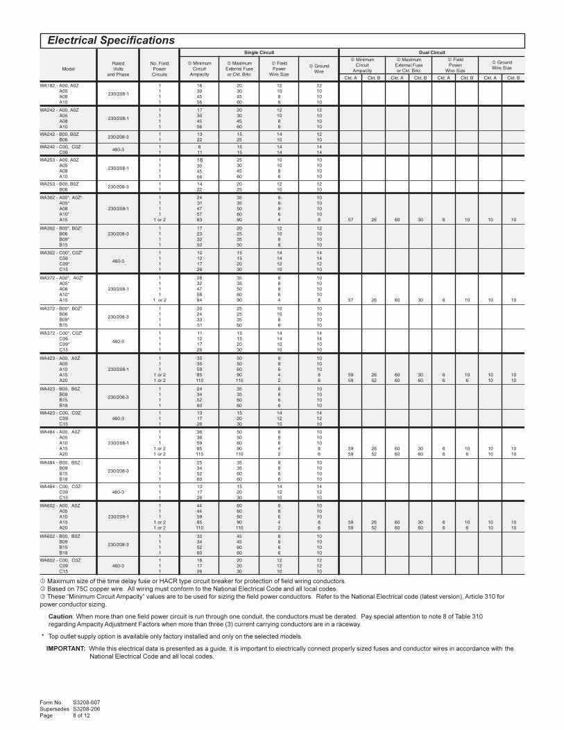
1 Maximum size of the time delay fuse or HACR type circuit breaker for protection of field wiring conductors.
2 Based on 75C copper wire. All wiring must conform to the National Electrical Code and all local codes.
3 These “Minimum Circuit Ampacity” values are to be used for sizing the field power conductors. Refer to the National Electrical code (latest version), Article 310 for
power conductor sizing.
Caution: When more than one field power circuit is run through one conduit, the conductors must be derated. Pay special attention to note 8 of Table 310
regarding Ampacity Adjustment Factors when more than three (3) current carrying conductors are in a raceway.
* Top outlet supply option is available only factory installed and only on the selected models.
IMPORTANT: While this electrical data is presented as a guide, it is important to electrically connect properly sized fuses and conductor wires in accordance with the
National Electrical Code and all local codes.
tiucriCelgniS tiucriClauD
ledoMdetaRstloV
esahPdna
dleiF.oNrewoPstiucriC
3 muminiMtiucriCyticapmA
1 mumixaMesuFlanretxE.rkrB.tkCro
2 dleiFrewoPeziSeriW
2 dnuorGeriW
3 muminiMtiucriCyticapmA
1 mumixaMesuFlanretxE.rkrB.tkCro
2 dleiFrewoPeziSeriW
2 dnuorGeziSeriW
A.tkC B.tkC A.tkC B.tkC A.tkC B.tkC A.tkC B.tkC
Z0A,00A-281AW50A80A01A
1-802/032
1111
61035465
02035406
210186
21010101
Z0A,00A-242AW50A80A01A
1-802/032
1111
71035465
02035406
210186
21010101
Z0B,00B-242AW60B
3-802/03211
3122
5152
4101
2101
Z0C,00C-242AW60C
3-06411
811
5151
4141
4141
Z0A,00A-352AW50A80A01A
1-802/032
1111
81035465
52035406
010186
01010101
Z0B,00B-352AW60B
3-802/03211
4122
0252
2101
2101
*Z0A,*00A-203AW*50A
80A*01A
51A
1-802/032
1111
2ro1
4213747538
5353050609
88864
010101018 75 62 06 03 6 01 01 01
*Z0B,*00B-203AW60B*90B
51B
3-802/0321111
71322305
02525305
210188
21010101
*Z0C,*00C-203AW60C*90C
51C
3-064
1111
01217162
51510203
41412101
41412101
*Z0A,*00A-273AW*50A
80A*01A
51A
1-802/032
1111
2ro1
8223748548
5353050609
88864
010101018 75 62 06 03 6 01 01 01
*Z0B,*00B-273AW60B*90B
51B
3-802/032
1111
02423315
52525306
010186
01010101
*Z0C,*00C-273AW60C*90C
51C
3-064
1111
11217162
51510203
41410101
41410101
Z0A,00A-324AW50A01A51A02A
1-802/032
111
2ro12ro1
53539558011
05050609011
88642
01010186
9595
6225
0606
0306
66
016
0101
0101
Z0B,00B-324AW90B51B81B
3-802/032
1111
42432506
53530606
8866
01010101
Z0C,00C-324AW90C51C
3-064111
317162
510203
412101
412101
Z0A,00A-484AW50A01A51A02A
1-802/032
111
2ro12ro1
63639558011
05050609011
88642
01010186
9595
6225
0606
0306
66
016
0101
0101
Z0B,00B-484AW90B51B81B
3-802/032
1111
52432506
53530606
8866
01010101
Z0C,00C-484AW90C51C
3-064111
317162
510203
412101
412101
Z0A,00A-206AW50A01A51A02A
1-802/032
111
2ro12ro1
44449558011
06060609011
88642
01010186
9595
6225
0606
0306
66
016
0101
0101
Z0B,00B-206AW90B51B81B
3-802/032
1111
23432506
54540606
8866
01010101
Z0C,00C-206AW90C51C
3-064111
617162
020203
212101
212101
Electrical Specifications

Form No. S3208-607Supersedes S3208-206Page 9 of 12
Above data is with 1" standard throwaway filter and 1" washable filter.
For optional 2" pleated filter - reduce ESP by .15 in.
See installation instructions for maximum ESP information on various KW application.
NOTE: Field installed Heater Packages are not approved for use with top supply opening models.
1 Model WA242 only.
PSEni
H2O
281AW242AW352AW
203AW273AW
324AW484AW
206AW
lioCteW/yrDdeepShgiHlioCteW/yrD
deepSwoLlioCteW/yrD
deepShgiHlioCteW/yrD
deepSwoLlioCteW/yrD
deepShgiHlioCteW/yrD
deepSwoLlioCteW/yrD
0 579/0201 5131/5931 539/059 0081/5881 0061/0561 0002/0022 0541/0061
1. 509/069 0721/0431 519/039 5661/0771 0051/0551 0091/0012 5731/5251
2. 008/568 0911/5821 588/019 0551/5361 0041/0541 0081/0002 0021/5641
3. 537/028 0011/5021 038/558 0041/0051 0031/0531 0071/5781 -/-
4. 056/537 0001/0111 557/008 5821/0731 5711/0031 0061/5771 -/-
5. 535/516 078/5001 -/- 0511/0521 -/- 5741/0561 -/-
lanimoNWK
)1(V042tA )1(V802tA )2(V084tA )2(V064tA
wK spmAhP-1 spmAhP-3 hutB wK spmAhP-1 spmAhP-3 hutB wK spmAhP-3 hutB wK spmAhP-3 hutB
0.5 0.5 8.02 560,71 57.3 0.81 997,21
0.6 0.6 4.41 874,02 05.4 5.21 953,51 0.6 2.7 874,02 25.5 9.6 048,81
0.8 0.8 3.33 403,72 00.6 8.82 874,02
0.9 0.9 7.12 717,03 57.6 7.81 830,32 0.9 8.01 717,03 82.8 4.01 062,82
0.01 0.01 7.14 031,43 05.7 1.63 895,52
0.51 0.51 5.26 1.63 591,15 52.11 1.45 2.13 693,83 0.51 0.81 591,15 08.31 3.71 990,74
0.81 0.81 3.34 434,16 05.31 5.73 670,64 0.81 7.12 434,16 65.61 8.02 915,65
0.02 0.02 3.38 062,86 00.51 1.27 591,15
.ylnostinuV802/032nielbaliavaerasretaehcirtceleesehT)1(
.ylnostinuV084nielbaliavaerasretaehcirtceleesehT)2(
stinUWK0ottaeHcirtcelEgniddarofdengiseD•sledoMV802/032nodradnatSrekaerBtiucriC•
sledoMV064nodradnatStcennocsiDelggoT•
detsiLLU•detsiLLUC•
renoitidnoCriAsledoM
sledoM00A-1-802/032
sledoM00B-3-802/032
sledoM00C-3-064
#ledoMretaeH WK #ledoMretaeH WK #ledoMretaeH WK
281AW50A-20AWHE80A-A20AWHE01A-A20AWHE
5801
A/N A/N
242AW352AW
50A-20AWHE80A-A20AWHE01A-A20AWHE
5801
60B-42AWHE 6 60C-B42HWHE 1 6
203AW
50A-30AWHE80A-30AWHE01A-30AWHE51A-30AWHE
580151
60B-30AWHE90B-30AWHE51B-30AWHE
6951
60C-A30CWHE90C-A30CWHE51C-A30AWHE
6951
273AW
50A-30AWHE80A-30AWHE01A-30AWHE51A-30AWHE
580151
60B-30AWHE90B-30AWHE51B-73AWHE
6951
60C-A30CWHE90C-A30CWHE51C-A30AWHE
6951
324AW484AW
50A-50AWHE01A-50AWHE51A-50AWHE02A-50AWHE
5015102
90B-50AWHE51B-50AWHE81B-50AWHE
95181
90C-A50AWHE51C-A50AWHE
951
206AW
50A-06AWHE01A-50AWHE51A-50AWHE02A-50AWHE
5015102
90B-06AWHE51B-50AWHE81B-50AWHE
95181
90C-A50AWHE51C-A50AWHE
951
Heater Packages - Field Installed
Indoor Blower Performance - CFM at 230 or 460 Volts
Electric Heat Table - Refer to Electrical Specifications for Availability by Unit Model

Form No. S3208-607Supersedes S3208-206Page 10 of 12
1 Below 65oF (18.3C), unit requires a factory or field installed low ambient control.
2 Return air temperature.
ledoM.B.W/.B.D
2
gnilooCyticapaC
57 oF 08 oF 58 oF 09 oF 59 oF 001 oF 501 oF 011 oF 511 oF 021 oF 521 oF
281AW
/5726
gnilooClatoTgnilooCelbisneS
006,91528,41
576,81007,41
527,71574,41
528,61091,41
529,51038,31
050,51093,31
571,41088,21
523,31003,21
005,21046,11
007,11007,01
001,11051,01
/0876
gnilooClatoTgnilooCelbisneS
579,02526,41
063,02564,41
017,91003,41
020,91531,41
003,81079,31
045,71046,31
057,61032,31
029,51027,21
060,51521,21
004,41006,11
008,31000,11
/5827
gnilooClatoTgnilooCelbisneS
059,42057,41
087,32026,41
026,22004,41
064,12090,41
513,02096,31
081,91091,31
050,81016,21
039,61039,11
518,51551,11
007,41004,01
006,31056,9
242AW
/5726
gnilooClatoTgnilooCelbisneS
009,42009,91
088,32035,91
078,22041,91
076,12027,81
088,02572,81
009,91008,71
029,81003,71
069,71077,61
000,71512,61
050,61003,51
050,51003,41
/0876
gnilooClatoTgnilooCelbisneS
006,62003,91
040,62061,91
024,52079,81
047,42047,81
000,42064,81
012,32041,81
053,22077,71
054,12053,71
084,02098,61
000,91007,51
055,71004,41
/5827
gnilooClatoTgnilooCelbisneS
003,13577,91
053,03034,91
062,92040,91
020,82095,81
046,62090,81
011,52035,71
044,32029,61
026,12062,61
006,02045,51
574,91007,41
004,81009,31
352AW
/5726
gnilooClatoTgnilooCelbisneS
004,32001,91
006,22007,81
008,12004,81
000,12009,71
001,02006,71
002,91001,71
003,81006,61
004,71002,61
004,61006,51
004,51001,51
003,41006,41
/0876
gnilooClatoTgnilooCelbisneS
009,42005,81
006,42003,81
002,42002,81
007,32009,71
000,32007,71
003,22004,71
005,12000,71
007,02007,61
007,91002,61
006,81008,51
004,71003,51
/5827
gnilooClatoTgnilooCelbisneS
007,92000,91
008,82006,81
008,72003,81
008,62008,71
006,52004,71
004,42009,61
002,32002,61
001,22007,51
007,02000,51
004,91003,41
009,71006,31
203AW
/5726
gnilooClatoTgnilooCelbisneS
009,03007,52
007,92003,52
005,82009,42
004,72004,42
001,62009,32
001,52003,32
000,42007,22
009,22002,22
009,12005,12
008,02008,02
007,91001,02
/0876
gnilooClatoTgnilooCelbisneS
000,33009,42
003,23008,42
006,13006,42
009,03004,42
000,03001,42
002,92007,32
003,82003,32
003,72009,22
003,62003,22
002,52007,12
000,42001,12
/5827
gnilooClatoTgnilooCelbisneS
003,93005,52
008,73002,52
003,63007,42
009,43003,42
004,33007,32
000,23000,32
005,03002,22
001,92005,12
007,72006,02
002,62006,91
007,42007,81
273AW
/5726
gnilooClatoTgnilooCelbisneS
003,73001,82
007,53007,72
002,43003,72
008,23008,62
004,13004,62
001,03008,52
009,82002,52
008,72005,42
007,62008,32
007,52009,22
006,42001,22
/0876
gnilooClatoTgnilooCelbisneS
008,93002,72
009,83001,72
000,83000,72
000,73008,62
000,63006,62
001,53002,62
001,43008,52
001,33003,52
001,23007,42
001,13000,42
000,03002,32
/5827
gnilooClatoTgnilooCelbisneS
004,74009,72
005,54005,72
007,34002,72
008,14006,62
000,04001,62
004,83004,52
008,63006,42
002,53007,32
008,33008,22
003,23007,12
009,03006,02
324AW
/5726
gnilooClatoTgnilooCelbisneS
002,34000,53
007,14003,43
001,04005,33
004,83008,23
006,63000,23
008,43002,13
000,33002,03
000,13003,92
000,92003,82
009,62002,72
007,42001,62
/0876
gnilooClatoTgnilooCelbisneS
001,64009,33
004,54006,33
005,44002,33
004,34008,23
000,24003,23
005,04007,13
009,83000,13
000,73003,03
009,43004,92
006,23005,82
001,03005,72
/5827
gnilooClatoTgnilooCelbisneS
009,45007,43
001,35001,43
001,15004,33
000,94006,23
007,64007,13
003,44007,03
000,24006,92
004,93004,82
007,63001,72
009,33008,52
000,13004,42
484AW
/5726
gnilooClatoTgnilooCelbisneS
002,84021,93
003,64025,83
056,44086,73
070,34015,73
003,14000,73
043,93031,63
091,73019,43
048,43033,33
003,23004,13
009,03000,03
005,92007,82
/0876
gnilooClatoTgnilooCelbisneS
044,15059,73
044,05008,73
046,94006,73
057,84004,73
005,74003,73
098,54047,63
029,34008,53
095,14094,43
009,83008,23
001,83050,23
052,73053,13
/5827
gnilooClatoTgnilooCelbisneS
009,95057,83
056,85052,83
042,75054,73
053,55032,73
007,25006,63
007,94075,53
007,64051,43
008,34023,23
058,04001,03
001,93007,82
054,73005,72
206AW
/5726
gnilooClatoTgnilooCelbisneS
053,06071,54
005,75007,34
036,45081,24
023,25011,14
000,05000,04
066,74048,83
092,54046,73
019,24093,63
005,04001,53
A/NA/N
A/NA/N
/0876
gnilooClatoTgnilooCelbisneS
006,46059,34
057,26069,24
096,06038,14
091,95051,14
005,75004,04
016,55075,93
045,35066,83
062,15076,73
008,84006,63
A/NA/N
A/NA/N
/5827
gnilooClatoTgnilooCelbisneS
008,67009,44
003,37074,34
016,96079,14
047,66048,04
008,36006,93
087,06062,83
007,75018,63
035,45062,53
003,15006,33
A/NA/N
A/NA/N
srotcaFreilpitluMyticapaC
wolfriAdetaRfo% 01- detaR 01+
HUTBlatoTHUTBelbisneS
579.0059.0
0.10.1
20.150.1
Cooling Application Data - Outdoor Temperature 1

Form No. S3208-607Supersedes S3208-206Page 11 of 12
1 Low ambient control is required with economizer for low temperature compressor operation.
2 For use only with “V” Control Module and TCS22 Controller.
3 Intake and exhaust can be independently adjusted.
STD = Standard equipment for these specified models.
1 TDR. Time delay relay only for compressor is fixed 5-minute delay-on-break to prevent short cycling. Not needed if HPC or LPC are used. See notes 2, 3 and 4.
2 HPC. High pressure control is auto reset. Always used with compressor control module (CCM) which is included. See note 4.
3 LPC. Low pressure control is auto reset. Always used with compressor control module (CCM) which is included. See note 4.
4 CCM. Compressor control module has adjustable 30-second to 5-minute delay-on-break timer. On initial power-up, or any time the power is interrupted, the delay-on-make will be 2-
minutes plus 10% of the delay-on-break setting. There is no delay-on-make during routine operation of the unit. The module also provides the lockout feature (with 1 retry) for
high and/or low-pressure controls, and a 2-minute timed bypass for low-pressure control.
5 LAC. Low ambient control permits cooling operation down to 0°F
6 ALR. The alarm relay has a set of normally open and normally closed dry contacts to provide the ability to signal a condition of shutdown on either high or low pressure controls.
7 SK. Start kit can be used with all -A single phase models only. Is not used or available for -B or -C three phase models.
8 ODT. Outdoor thermostat is adjustable from 0 to 50°F. It is suitable for use as a compressor cut-off thermostat.
9 DDC. Incorporates 4 additional sensors: discharge air temperature, indoor blower airflow, compressor current, and dirty filter. These sensing devices function to input analog data
such as temperature, as well as digital data such as airflow, compressor status or filter status.
� “V” control module should be ordered in conjunction with direct digital controller (DDC) model TCS22. Refer to DDC specification sheet S3280 for more information.� Use CMA-24 for Model WA423. � Use CMA-23 for Models WA253.
sledoM 352AW,242AW,281AW 273AW,203AW 206AW,484AW,324AW
noitpircseDdellatsnIyrotcaF
.oNedoCdellatsnIdleiF
.oNtraPdellatsnIyrotcaF
.oNedoCdellatsnIdleiF
.oNtraPdellatsnIyrotcaF
.oNedoCdellatsnIdleiF
.oNtraPdradnatS-repmaDriAhserFcirtemoraB X 2-DAFB X 3-DAFB X 5-DAFB
etalPffO-knalB B 2-POB B 3-POB B 5-POBrepmaDriAhserFdezirotoM M 2-DAFM M 3-DAFM M 5-DAFM
tsuahxE/wnruteRgnirpS-rotalitneVlaicremmoC V 2-VRC V 3-SVRC V 5-SVRCtsuahxE/wnruteRrewoP-rotalitneVlaicremmoC --- --- P 3-PVRC P 5-PVRC
gnitaludoMylluF-rezimonocE 1 E B2-MFIE E C3-MFIE E C5-MFIEgnitaludoMylluF-rezimonocE 21 D A/N D A/N D A/N
tloV032-rotalitneVyrevoceRygrenE R B2A-VREW R C3A-VREW 3 R C5A-VREW 3
tloV064-rotalitneVyrevoceRygrenE A/N A/N R C3C-VREW 3 R C5C-VREW 3
Ventilation Options
seludoMlortnoCgninoitidnoCriA 324AW,273AW,203AW,242AW,281AWsledoMSNOITPOLORTNOCELBALIAVA
RDT 1 CPH 2 CPL 3 MCC 4 CAL 5 RLA 6 KS 7 TDO 8 CDD 9 edoCdellatsnIyrotcaF traPdellatsnIdleiF� D 5-AMC
� E 6-AMC� � � G A01-AMC� � � � H A31-AMC
� � I 21-AMC� � � � � J ylnOyrotcaF� � � � � K 51-CMC&A31-AMC� � � � � � M ylnOyrotcaF
� ylnOdellatsnIdleiF 51-CMC� ylnOdellatsnIdleiF 41-AMC
� � � � � � V � ylnOyrotcaF� ylnOdellatsnIdleiF 32-AMC �
seludoMlortnoCgninoitidnoCriA sledoM206AW,484AW,352AWSNOITPOLORTNOCELBALIAVA
RDT 1 CPH 2 CPL 3 MCC 4 CAL 5 RLA 6 KS 7 TDO 8 CDD 9 edoCdellatsnIyrotcaF traPdellatsnIdleiF
seoDtoNylppA
oTesehTsledoM
DTS � DTS G A61-AMCDTS � DTS � H A81-AMCDTS DTS � I 6-AMCDTS � DTS � � J ylnOyrotcaFDTS � DTS � � K 51-CMC&A31-AMCDTS � DTS � � � M ylnOyrotcaFDTS DTS � ylnOdellatsnIdleiF 51-CMCDTS DTS � ylnOdellatsnIdleiF 41-AMCDTS � DTS � � � V � ylnOyrotcaFDTS DTS � ylnOdellatsnIdleiF 42-AMC �
MODEL NUMBER | | CONTROL MODULES
(See Chart Below)REVISION
VOLTS & PHASE |
A - 230/208/60/1
B - 230/208/60/3
C - 460/60/3
KW
COLOR OPTIONS
X - Beige (Standard)
1 - White
2 - Mesa Tan
4 - Buckeye Gray
5 - Desert Brown
8 - Dark BronzeFILTER OPTIONS
X - 1-inch Throwaway (Standard)
W - 1-inch Washable
P - 2-inch Pleated
| COIL OPTIONS
X - Standard
1 - Phenolic Coated Evaporator
2 - Phenolic Coated Condenser
3 - Phenolic Coated Evaporator
and Condenser
| OUTLET OPTIONS
X - Front (Standard)
T - Top (on WA30 and
WA37 Models)
CAPACITY |
18 - 1½ Ton
24 - 2 Ton
25 - 2 Ton
30 - 2½ Ton
37 - 3 Ton
42 - 3½ Ton
48 - 4 Ton
60 - 5 Ton
WA 37 2 A 10 X X X X X X
Note: For 0KW and circuit breakers (230/208 Volt) or toggle disconnects (460 Volt) applications, insert 0Z in the KW field of the model number.
VENTILATION OPTIONS
(See Table Below)
Air Conditioning Wall-Mount Model Nomenclature

Manual 2100-398C
Page 1 of 21
INSTALLATION INSTRUCTIONS
WALL MOUNTED
PACKAGE AIR CONDITIONERS
MODELS
WA381
WA423
WA484
WA491
WA602
Manual : 2100-398C
Supersedes: 2100-398B
File: Volume III Tab 16
Date: 08-01-07
Bard Manufacturing Company, Inc.
Bryan, Ohio 43506
Since 1914...Moving ahead just as planned.
© Copyright 2002

Manual 2100-398C
Page 2 of 21
Contents
FiguresFigure 1 Unit Dimensions ...................................... 5Figure 2 Fresh Air Damper Assembly ................... 8Figure 3 Mounting Instructions ............................ 10Figure 4 Electric Heat Clearance .........................11Figure 5 Wall Mounting Instructions .................... 12Figure 6 Wall Mounting Instructions .................... 12Figure 7 Common Wall Mounting Installations .... 13Figure 8 Unit 24V Terminal Board ....................... 15Figure 9 Fan Blade Setting ................................. 18
TablesTable 1 Electric Heat Table .................................. 4Table 2 Electrical Specifications ................ 6 and 7Table 3 Thermostat Wire Size ........................... 14Table 4 Wall Thermostat .................................... 14Table 5 Fan Blade Dimensions .......................... 18Table 6 Refrigerant Charge ............................... 18Table 7 Indoor Blower Performance .................. 18Table 7A Indoor Blower Performance .................. 19Table 8 Recommended Airflow .......................... 19Table 9 Maximum ESP Electric Heat Only ........ 19Table 9A Maximum ESP Electric Heat Only ........ 19Table 10 Pressure Table ...................................... 20Table 11 Optional Accessories ............................ 21
Getting Other Information and Publications 3
Wall Mount General InformationHeat Pump Wall Mount Model Nomenclature .......... 4Shipping Damage .................................................... 7General ................................................................ 7Duct Work ................................................................ 8Filters ................................................................ 8Fresh Air Intake ....................................................... 8Condensate Drain .................................................... 8
Installation InstructionsWall Mounting Information ....................................... 9Mounting the Unit .................................................... 9Wiring – Main Power ............................................. 14Wiring – Low Voltage Wiring ................................. 14
Start UpImportant Installer Note ......................................... 16High Pressure Switch ............................................ 16Three Phase Scroll Compressor Start Up .............. 16Phase Monitor ....................................................... 16Condenser Fan Operation ..................................... 16Service Hints ......................................................... 16Sequence of Operation .......................................... 17Compressor Control Module .................................. 17Adjustments ........................................................... 17Pressure Service Ports .......................................... 17
TroubleshootingFan Blade Setting Dimensions .............................. 18Removal of Fan Shroud ......................................... 18Refrigerant Charge ................................................ 18Pressure Table – Cooling ...................................... 20Optional Accessories ............................................. 21

Manual 2100-398CPage 3 of 21
GETTING OTHER INFORMATION AND PUBLICATIONS
These publications can help you install the air
conditioner or heat pump. You can usually find these at
your local library or purchase them directly from the
publisher. Be sure to consult current edition of each
standard.
National Electrical Code ...................... ANSI/NFPA 70
Standard for the Installation .............. ANSI/NFPA 90A
of Air Conditioning and Ventilating Systems
Standard for Warm Air ...................... ANSI/NFPA 90B
Heating and Air Conditioning Systems
Load Calculation for ............................ ACCA Manual J
Residential Winter and Summer Air Conditioning
Duct Design for Residential .............. ACCA Manual D
Winter and Summer Air Conditioning and Equipment
Selection
FOR MORE INFORMATION, CONTACTTHESE PUBLISHERS:
ACCA Air Conditioning Contractors of America
1712 New Hampshire Ave. N.W.
Washington, DC 20009
Telephone: (202) 483-9370
Fax: (202) 234-4721
ANSI American National Standards Institute
11 West Street, 13th Floor
New York, NY 10036
Telephone: (212) 642-4900
Fax: (212) 302-1286
ASHRAE American Society of Heating, Refrigeration
and Air Conditioning Engineers, Inc.
1791 Tullie Circle, N.E.
Atlanta, GA 30329-2305
Telephone: (404) 636-8400
Fax: (404) 321-5478
NFPA National Fire Protection Association
Batterymarch Park
P.O. Box 9101
Quincy, MA 02269-9901
Telephone: (800) 344-3555
Fax: (617) 984-7057
Manufactured under the followingU.S. Patent numbers:
5,485,878; 5,301,777; 5,002,116; 4,924,934;4,875,520; 4,825,936

Manual 2100-398CPage 4 of 21
WALL MOUNT GENERAL INFORMATION
AIR CONDITIONER WALL MOUNT MODEL NOMENCLATURE
WA 42 3 – A 10 X X X X X A
NOTE: All vent options are without exhaust capability. May require separate field supplied barometric relief in building.
TABLE 1ELECTRIC HEAT TABLE
sledoM
A-183AWA-324AWA-484AWA-194AWA-206AW
B-183AWB-324AWB-484AWB-194AWB-206AW
C-183AWC-324AWC-484AWC-194AWC-206AW
1-032 1-802 3-032 3-802 3-064
WK A UTB A UTB A UTB A UTB A UTB
5 8.02 05071 1.81 00821 --- --- --- --- --- ---
6 --- --- --- --- 4.41 00502 5.21 06351 2.7 08402
8 3.33 08272 8.82 05402 --- --- --- --- --- ---
9 --- --- --- --- 7.12 00603 7.81 03032 8.01 00703
01 6.14 03143 2.63 00652 --- --- --- --- --- ---
51 5.26 00215 0.45 00483 2.63 00215 2.13 00483 3.71 00074
81 --- --- --- --- 3.34 03416 5.73 00164 --- ---
02 2.38 06286 1.27 00215 --- --- --- --- --- ---
KW
MODEL NUMBER CONTROL MODULES
(See Spec. Sheet S3208 or
S3348 for the WA381 & WA491)
VOLTS & PHASE
A - 230/208/60/1
B - 230/208/60/3
C - 460/60/3
REVISIONS
VENTILATION OPTIONS
X - Barometric Fresh Air Damper (Standard)
B - Blank-off Plate
M - Motorized Fresh Air Damper
V - Commercial Ventilator - Motorized with Exhaust
E - Economizer (Internal) - Fully Modulating with Exhaust
R - Energy Recovery Ventilator - Motorized with Exhaust
FILTER OPTIONS
X - One Inch Throwaway (Standard)
W - One Inch Washable
P - Two Inch Pleated
COLOR OPTIONS
X - Beige (Standard)
1 - White
2 - Mesa Tan
4 - Buckeye Gray
5 - Desert Brown
6 - Dark Bronze
COIL OPTIONS
X - Standard
1 - Phenolic Coated Evaporator
2 - Phenolic Coated Condenser
3 - Phenolic Coated Evaporator
and Condenser
OUTLET OPTIONS
X - Front (Standard)
CAPACITY
38 - 3 Ton
42 - 3½ Ton
48 - 4 Ton
60 - 5 Ton

Manual 2100-398CPage 5 of 21
FIG
UR
E 1
UN
IT D
IME
NS
ION
S
ledoM
htdiW
)W(
htpeD
)D(
thgieH
)H(
ylppuSnrute
R
EF
GI
JK
LM
NO
PQ
RS
TA
BC
B
83A
W24
AW
84A
W94
AW
06A
W
570.24234.22
578.4888.9
88.9288.51
88.9288.34
01.9166.13
00.0386.23
49.6296.43
34.2373.3
88.2488.32
00.0144.1
00.6188.1
FR
ON
T V
IEW
BA
CK
VIE
WS
IDE
VIE
W

Manual 2100-398CPage 6 of 21
1 Maximum size of the time delay fuse or HACR type circuit breaker for protection of field wiring conductors.
2 Based on 75° C copper wire. All wiring must conform to NEC and all local codes.
3 These “Minimum Circuit Ampacity” values are to be used for sizing the field power conductors. Refer to the National Electric
Code (latest revision), article 310 for power conductor sizing.
CAUTION: When more than one field power conductor circuit is run through one conduit, the conductors must be derated. Pay
special attention to note 8 of table 310 regarding Ampacity Adjustment Factors when more than 3 conductors are in a
raceway.
TABLE 2ELECTRICAL SPECIFICATIONS
ledoM
TIUCRICELGNIS TIUCRICLAUD
detaR&stloVesahP
.oNdleiFrewoPstiucriC
3
muminiMtiucriCyticapmA
1
mumixaMlanretxEroesuFtiucriCrekaerB
2
dleiFrewoP
eriWeziS
2
dnuorGeriWeziS
3
muminiMtiucriCyticapmA
1
mumixaMesuFlanretxE
tiucriCrorekaerB
2
rewoPdleiFeziSeriW
2
dnuorGeziSeriW
ATKC BTKC ATKC BTKC ATKC BTKC ATKC BTKC
Z0A,00A-183AW50A80A01A
1-802/032
1111
52237485
53530506
8886
01010101
A/NA/NA/NA/N
A/NA/NA/NA/N
A/NA/NA/NA/N
A/NA/NA/NA/N
A/NA/NA/NA/N
A/NA/NA/NA/N
A/NA/NA/NA/N
A/NA/NA/NA/N
Z0B,00B-183AW60B90B
3-802/032111
024233
030353
01018
010101
A/NA/NA/N
A/NA/NA/N
A/NA/NA/N
A/NA/NA/N
A/NA/NA/N
A/NA/NA/N
A/NA/NA/N
A/NA/NA/N
Z0C,00C-183AW60C90C
3-064111
113171
515102
414121
414121
A/NA/NA/N
A/NA/NA/N
A/NA/NA/N
A/NA/NA/N
A/NA/NA/N
A/NA/NA/N
A/NA/NA/N
A/NA/NA/N
Z0A,00A-324AW50A01A51A02A
1-802/032
111
2ro12ro1
53539558011
05050609011
88642
01010186
A/NA/NA/N6565
A/NA/NA/N6225
A/NA/NA/N0606
A/NA/NA/N0306
A/NA/NA/N
66
A/NA/NA/N016
A/NA/NA/N0101
A/NA/NA/N0101
Z0B,00B-324AW90B51B81B
3-802/032
1111
42432506
53530506
8866
01010101
A/NA/NA/NA/N
A/NA/NA/NA/N
A/NA/NA/NA/N
A/NA/NA/NA/N
A/NA/NA/NA/N
A/NA/NA/NA/N
A/NA/NA/NA/N
A/NA/NA/NA/N
Z0C,00C-324AW90C51C
3-064111
317162
510203
412101
412101
A/NA/NA/N
A/NA/NA/N
A/NA/NA/N
A/NA/NA/N
A/NA/NA/N
A/NA/NA/N
A/NA/NA/N
A/NA/NA/N
Z0A,00A-484AW50A01A51A02A
1-802/032
111
2ro12ro1
63639558011
05050609011
88642
01010186
A/NA/NA/N9595
A/NA/NA/N6225
A/NA/NA/N0606
A/NA/NA/N0306
A/NA/NA/N
66
A/NA/NA/N016
A/NA/NA/N0101
A/NA/NA/N0101
Z0B,00B-484AW90B51B81B
3-802/032
1111
52432506
53530606
8866
01010101
A/NA/NA/NA/N
A/NA/NA/NA/N
A/NA/NA/NA/N
A/NA/NA/NA/N
A/NA/NA/NA/N
A/NA/NA/NA/N
A/NA/NA/NA/N
A/NA/NA/NA/N
Z0C,00C-484AW90C51C
3-064111
317162
510203
412101
412101
A/NA/NA/N
A/NA/NA/N
A/NA/NA/N
A/NA/NA/N
A/NA/NA/N
A/NA/NA/N
A/NA/NA/N
A/NA/NA/N
Z0A,00A-194AW50A80A01A
1-802/032
1111
33337485
05050506
8886
01010101
A/NA/NA/NA/N
A/NA/NA/NA/N
A/NA/NA/NA/N
A/NA/NA/NA/N
A/NA/NA/NA/N
A/NA/NA/NA/N
A/NA/NA/NA/N
A/NA/NA/NA/N
Z0B,00B-194AW60B90B
3-802/032111
727233
040404
888
010101
A/NA/NA/N
A/NA/NA/N
A/NA/NA/N
A/NA/NA/N
A/NA/NA/N
A/NA/NA/N
A/NA/NA/N
A/NA/NA/N
Z0C,00C-194AW60C01C
3-064111
313171
515102
414121
414121
A/NA/NA/N
A/NA/NA/N
A/NA/NA/N
A/NA/NA/N
A/NA/NA/N
A/NA/NA/N
A/NA/NA/N
A/NA/NA/N
7EGAPNODEUNITNOCELBAT

Manual 2100-398CPage 7 of 21
SHIPPING DAMAGE
Upon receipt of equipment, the carton should be
checked for external signs of shipping damage. If
damage is found, the receiving party must contact the
last carrier immediately, preferably in writing,
requesting inspection by the carrier’s agent.
GENERAL
The equipment covered in this manual is to be installed
by trained, experienced service and installation
technicians.
The refrigerant system is completely assembled and
charged. All internal wiring is complete.
The unit is designed for use with or without duct work.
Flanges are provided for attaching the supply and return
ducts.
These instructions explain the recommended method to
install the air cooled self-contained unit and the
electrical wiring connections to the unit.
These instructions and any instructions packaged with
any separate equipment required to make up the entire
air conditioning system should be carefully read before
beginning the installation. Note particularly “Starting
Procedure” and any tags and/or labels attached to the
equipment.
While these instructions are intended as a general
recommended guide, they do not supersede any national
and/or local codes in any way. Authorities having
jurisdiction should be consulted before the installation is
made. See Page 3 for information on codes and
standards.
Size of unit for a proposed installation should be based
on heat loss calculation made according to methods of
Air Conditioning Contractors of America (ACCA). The
air duct should be installed in accordance with the
Standards of the National Fire Protection Association
for the Installation of Air Conditioning and Ventilating
Systems of Other Than Residence Type, NFPA No.
90A, and Residence Type Warm Air Heating and Air
Conditioning Systems, NFPA No. 90B. Where local
regulations are at a variance with instructions, installer
should adhere to local codes.
6EGAPMORFDEUNITNOCELBAT
ledoM
TIUCRICELGNIS TIUCRICLAUD
detaR&stloVesahP
.oNdleiFrewoPstiucriC
3
muminiMtiucriCyticapmA
1
mumixaMlanretxEroesuFtiucriCrekaerB
2
dleiFrewoP
eriWeziS
2
dnuorGeriWeziS
3
muminiMtiucriCyticapmA
1
mumixaMesuFlanretxE
tiucriCrorekaerB
2
rewoPdleiFeziSeriW
2
dnuorGeziSeriW
ATKC BTKC ATKC BTKC ATKC BTKC ATKC BTKC
Z0A,00A-206AW50A01A51A02A
1-802/032
111
2ro12ro1
44445558011
06060609011
88642
01010186
A/NA/NA/N9595
A/NA/NA/N6225
A/NA/NA/N0606
A/NA/NA/N0306
A/NA/NA/N
66
A/NA/NA/N016
A/NA/NA/N0101
A/NA/NA/N0101
Z0B,00B-206AW90B51B81B
3-802/032
1111
23432506
54540606
8866
01010101
A/NA/NA/NA/N
A/NA/NA/NA/N
A/NA/NA/NA/N
A/NA/NA/NA/N
A/NA/NA/NA/N
A/NA/NA/NA/N
A/NA/NA/NA/N
A/NA/NA/NA/N
Z0C,00C-206AW90C51C
3-064111
617162
020203
212101
212101
A/NA/NA/N
A/NA/NA/N
A/NA/NA/N
A/NA/NA/N
A/NA/NA/N
A/NA/NA/N
A/NA/NA/N
A/NA/NA/N
1 Maximum size of the time delay fuse or HACR type circuit breaker for protection of field wiring conductors.
2 Based on 75° C copper wire. All wiring must conform to NEC and all local codes.
3 These “Minimum Circuit Ampacity” values are to be used for sizing the field power conductors. Refer to the National Electric
Code (latest revision), article 310 for power conductor sizing.
CAUTION: When more than one field power conductor circuit is run through one conduit, the conductors must be derated. Pay
special attention to note 8 of table 310 regarding Ampacity Adjustment Factors when more than 3 conductors are in a
raceway.
Manual 2100-398CPage 8 of 21
FILTERS
A 1-inch throwaway filter is supplied with each unit.
The filter slides into position making it easy to service.
This filter can be serviced from the outside by removing
the service door. A 1-inch washable filter and 2-inch
pleated filter are also available as optional accessories.
The internal filter brackets are adjustable to
accommodate the 2-inch filter by loosening two (2)
screws on each bracket assembly and sliding the
brackets apart to the required width and retightening the
four (4) screws.
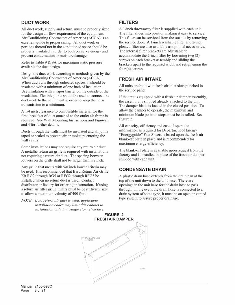
FRESH AIR INTAKE
All units are built with fresh air inlet slots punched in
the service panel.
If the unit is equipped with a fresh air damper assembly,
the assembly is shipped already attached to the unit.
The damper blade is locked in the closed position. To
allow the damper to operate, the maximum and
minimum blade position stops must be installed. See
Figure 2.
All capacity, efficiency and cost of operation
information as required for Department of Energy
“Energyguide” Fact Sheets is based upon the fresh air
blank-off plate in place and is recommended for
maximum energy efficiency.
The blank-off plate is available upon request from the
factory and is installed in place of the fresh air damper
shipped with each unit.
CONDENSATE DRAIN
A plastic drain hose extends from the drain pan at the
top of the unit down to the unit base. There are
openings in the unit base for the drain hose to pass
through. In the event the drain hose is connected to a
drain system of some type, it must be an open or vented
type system to assure proper drainage.
DUCT WORK
All duct work, supply and return, must be properly sized
for the design air flow requirement of the equipment.
Air Conditioning Contractors of America (ACCA) is an
excellent guide to proper sizing. All duct work or
portions thereof not in the conditioned space should be
properly insulated in order to both conserve energy and
prevent condensation or moisture damage.
Refer to Table 9 & 9A for maximum static pressure
available for duct design.
Design the duct work according to methods given by the
Air Conditioning Contractors of America (ACCA).
When duct runs through unheated spaces, it should be
insulated with a minimum of one inch of insulation.
Use insulation with a vapor barrier on the outside of the
insulation. Flexible joints should be used to connect the
duct work to the equipment in order to keep the noise
transmission to a minimum.
A 1/4 inch clearance to combustible material for the
first three feet of duct attached to the outlet air frame is
required. See Wall Mounting Instructions and Figures 3
and 4 for further details.
Ducts through the walls must be insulated and all joints
taped or sealed to prevent air or moisture entering the
wall cavity.
Some installations may not require any return air duct.
A metallic return air grille is required with installations
not requiring a return air duct. The spacing between
louvers on the grille shall not be larger than 5/8 inch.
Any grille that meets with 5/8 inch louver criteria may
be used. It is recommended that Bard Return Air Grille
Kit RG2 through RG5 or RFG2 through RFG5 be
installed when no return duct is used. Contact
distributor or factory for ordering information. If using
a return air filter grille, filters must be of sufficient size
to allow a maximum velocity of 400 fpm.
NOTE: If no return air duct is used, applicable
installation codes may limit this cabinet to
installation only in a single story structure.
FIGURE 2FRESH AIR DAMPER

Manual 2100-398CPage 9 of 21
INSTALLATION INSTRUCTIONS
WARNINGFailure to provide the 1/4 inch clearance
between the supply duct and a combustible
surface for the first 3 feet of duct can result in
fire causing damage, injury or death.
WALL MOUNTING INFORMATION
1. Two holes for the supply and return air openings
must be cut through the wall as shown in Figure 3.
2. On wood frame walls, the wall construction must be
strong and rigid enough to carry the weight of the
unit without transmitting any unit vibration.
3. Concrete block walls must be thoroughly inspected
to insure that they are capable of carrying the weight
of the installed unit.
MOUNTING THE UNIT
1. These units are secured by wall mounting brackets
which secure the unit to the outside wall surface at
both sides. A bottom mounting bracket is provided
for ease of installation, but is not required.
2. The unit itself is suitable for 0 inch clearance, but
the supply air duct flange and the first 3 feet of
supply air duct require a minimum of 1/4 inch
clearance to combustible material. If a combustible
wall, use a minimum of 30½" x 10½" dimensions for
sizing. However, it is generally recommended that a
1-inch clearance is used for ease of installation and
maintaining the required clearance to combustible
material. The supply air opening would then be
32" x 12". See Figures 3 and 4 for details.
3. Locate and mark lag bolt locations and bottom
mounting bracket location. See Figure 3.
4. Mount bottom mounting bracket.
5. Hook top rain flashing under back bend of top. Top
rain flashing is shipped secured to the right side of
the back.
6. Position unit in opening and secure with 5/16 lag
bolts; use 7/8 inch diameter flat washers on the lag
bolts.
7. Secure rain flashing to wall and caulk across entire
length of top. See Figure 3.
8. For additional mounting rigidity, the return air and
supply air frames or collars can be drilled and
screwed or welded to the structural wall itself
(depending upon wall construction). Be sure to
observe required clearance if combustible wall.
9. On side-by-side installations, maintain a minimum
of 20 inches clearance on right side to allow access
to control panel and heat strips, and to allow proper
airflow to the outdoor coil. Additional clearance
may be required to meet local or national codes.

Manual 2100-398CPage 10 of 21
FIG
UR
E 3
MO
UN
TIN
G IN
ST
RU
CT
ION
S
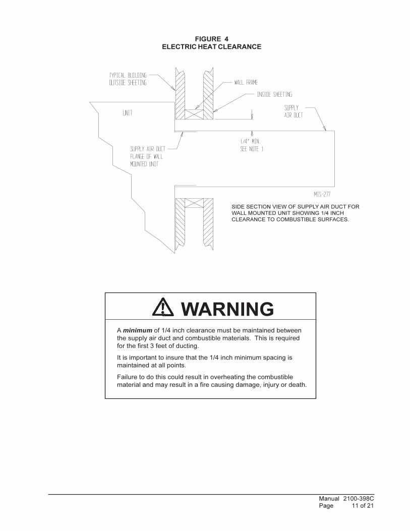
Manual 2100-398CPage 11 of 21
FIGURE 4ELECTRIC HEAT CLEARANCE
WARNINGA minimum of 1/4 inch clearance must be maintained between
the supply air duct and combustible materials. This is required
for the first 3 feet of ducting.
It is important to insure that the 1/4 inch minimum spacing is
maintained at all points.
Failure to do this could result in overheating the combustible
material and may result in a fire causing damage, injury or death.
SIDE SECTION VIEW OF SUPPLY AIR DUCT FOR
WALL MOUNTED UNIT SHOWING 1/4 INCH
CLEARANCE TO COMBUSTIBLE SURFACES.

Manual 2100-398CPage 12 of 21
FIGURE 5WALL MOUNTING INSTRUCTIONS
FIGURE 6WALL MOUNTING INSTRUCTIONS
SEE FIGURE 3 – MOUNTING INSTRUCTIONS
SEE UNIT DIMENSIONS, FIGURE
1, FOR ACTUAL DIMENSIONS
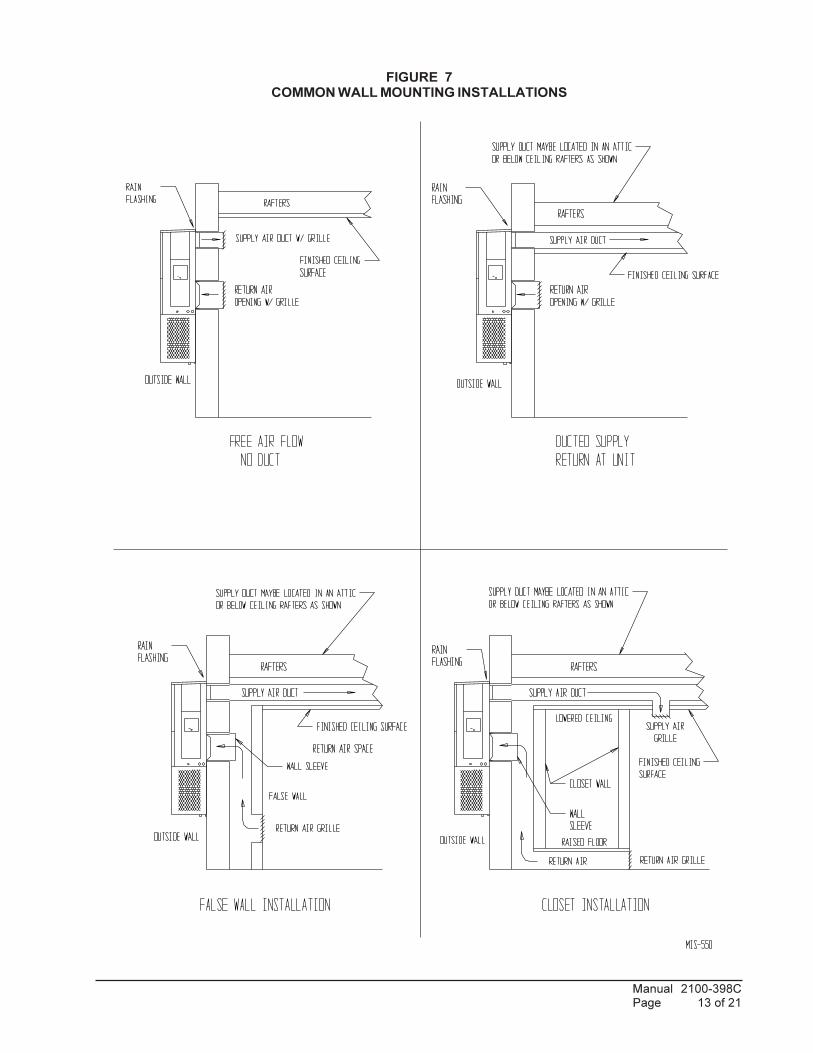
Manual 2100-398CPage 13 of 21
FIGURE 7COMMON WALL MOUNTING INSTALLATIONS

Manual 2100-398CPage 14 of 21
WIRING – MAIN POWER
Refer to the unit rating plate for wire sizing information
and maximum fuse or “HACR” type circuit breaker
size. Each outdoor unit is marked with a “Minimum
Circuit Ampacity”. This means that the field wiring
used must be sized to carry that amount of current.
Depending on the installed KW of electric heat, there
may be two field power circuits required. If this is the
case, the unit serial plate will so indicate. All models
are suitable only for connection with copper wire. Each
unit and/or wiring diagram will be marked “Use Copper
Conductors Only”. These instructions must be adhered
to. Refer to the National Electrical Code (NEC) for
complete current carrying capacity data on the various
insulation grades of wiring material. All wiring must
conform to NEC and all local codes.
The electrical data lists fuse and wire sizes (75° C
copper) for all models including the most commonly
used heater sizes. Also shown are the number of field
power circuits required for the various models with
heaters.
The unit rating plate lists a “Maximum Time Delay
Relay Fuse” or “HACR” type circuit breaker that is to
be used with the equipment. The correct size must be
used for proper circuit protection and also to assure that
there will be no nuisance tripping due to the momentary
high starting current of the compressor motor.
The disconnect access door on this unit may be locked
to prevent unauthorized access to the disconnect. To
convert for the locking capability, bend the tab located
in the bottom left-hand corner of the disconnect opening
under the disconnect access panel straight out. This tab
will now line up with the slot in the door. When shut, a
padlock may be placed through the hole in the tab
preventing entry.
See “Start Up” section for important information on
three phase scroll compressor start ups.
WIRING – LOW VOLTAGE WIRING
230/208V, 1 phase and 3 phase equipment dual primary
voltage transformers. All equipment leaves the factory
wired on 240V tap. For 208V operation, reconnect from
240V to 208V tap. The acceptable operating voltage
range for the 240 and 208V taps are:
TAP RANGE
240 253 – 216
208 220 – 187
NOTE: The voltage should be measured at the field power
connection point in the unit and while the unit is
operating at full load (maximum amperage
operating condition).
Five (5) wires should be run from thermostat subbase to
the 24V terminal board in the unit. A five conductor, 18
gauge copper, color-coded thermostat cable is
recommended. The connection points are shown in
Figure 8.
TABLE 3THERMOSTAT WIRE SIZE
remrofsnarTAV ALF eguaGeriW
mumixaMecnatsiDteeFnI
55 3.2
eguag02eguag81eguag61egaug41egaug21
5406001061052
TABLE 4WALL THERMOSTAT
tatsomrehT serutaeFetanimoderP
750-30483511D0225HT
taeHegats1,looCegats1elbammargorP-noNcinortcelE
revoegnahclaunaMrootuA
850-30481511D0225HT
taeHegats2,looCegats2elbammargorP-noNcinortcelE
revoegnahclaunaMrootuA
060-3048)544-0211(
taeHegats3;looCegats3cinortcelEelbammargorP-noN/elbammargorP
lanoitnevnoCroPHrevoegnahclaunaMrootuA

Manual 2100-398CPage 15 of 21
FIGURE 8UNIT 24V TERMINAL BOARD
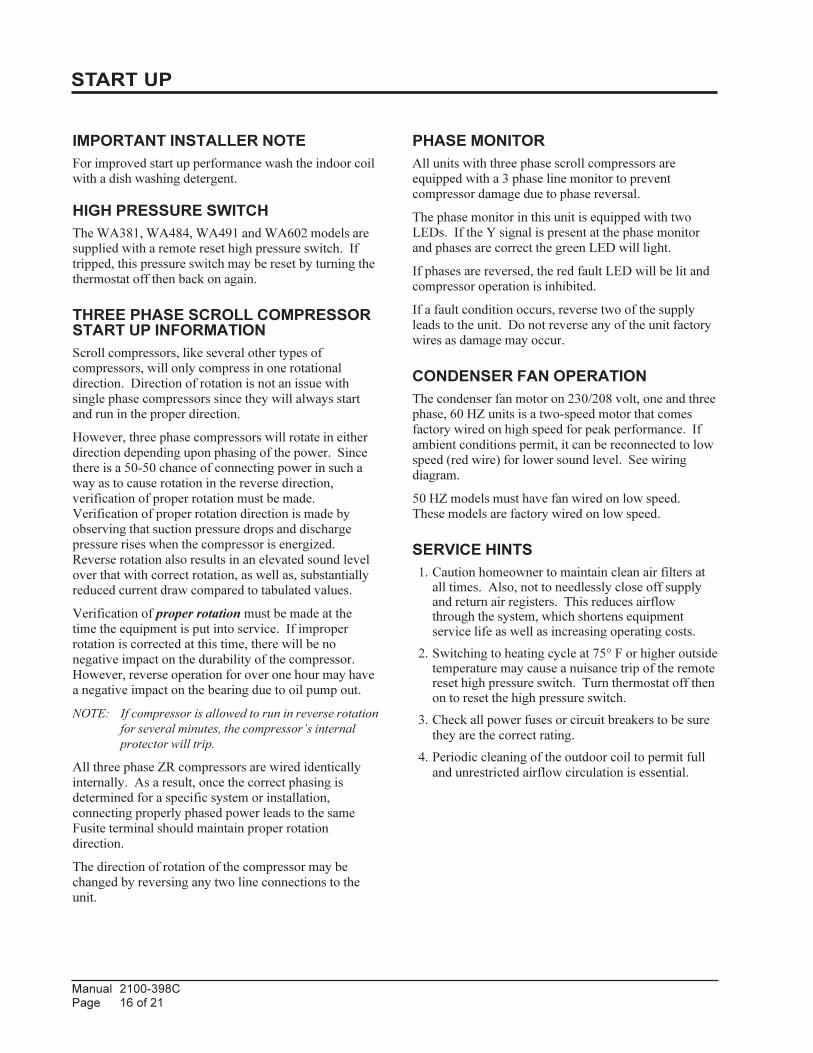
Manual 2100-398CPage 16 of 21
START UP
IMPORTANT INSTALLER NOTE
For improved start up performance wash the indoor coil
with a dish washing detergent.
HIGH PRESSURE SWITCH
The WA381, WA484, WA491 and WA602 models are
supplied with a remote reset high pressure switch. If
tripped, this pressure switch may be reset by turning the
thermostat off then back on again.
THREE PHASE SCROLL COMPRESSORSTART UP INFORMATION
Scroll compressors, like several other types of
compressors, will only compress in one rotational
direction. Direction of rotation is not an issue with
single phase compressors since they will always start
and run in the proper direction.
However, three phase compressors will rotate in either
direction depending upon phasing of the power. Since
there is a 50-50 chance of connecting power in such a
way as to cause rotation in the reverse direction,
verification of proper rotation must be made.
Verification of proper rotation direction is made by
observing that suction pressure drops and discharge
pressure rises when the compressor is energized.
Reverse rotation also results in an elevated sound level
over that with correct rotation, as well as, substantially
reduced current draw compared to tabulated values.
Verification of proper rotation must be made at the
time the equipment is put into service. If improper
rotation is corrected at this time, there will be no
negative impact on the durability of the compressor.
However, reverse operation for over one hour may have
a negative impact on the bearing due to oil pump out.
NOTE: If compressor is allowed to run in reverse rotation
for several minutes, the compressor’s internal
protector will trip.
All three phase ZR compressors are wired identically
internally. As a result, once the correct phasing is
determined for a specific system or installation,
connecting properly phased power leads to the same
Fusite terminal should maintain proper rotation
direction.
The direction of rotation of the compressor may be
changed by reversing any two line connections to the
unit.
PHASE MONITOR
All units with three phase scroll compressors are
equipped with a 3 phase line monitor to prevent
compressor damage due to phase reversal.
The phase monitor in this unit is equipped with two
LEDs. If the Y signal is present at the phase monitor
and phases are correct the green LED will light.
If phases are reversed, the red fault LED will be lit and
compressor operation is inhibited.
If a fault condition occurs, reverse two of the supply
leads to the unit. Do not reverse any of the unit factory
wires as damage may occur.
CONDENSER FAN OPERATION
The condenser fan motor on 230/208 volt, one and three
phase, 60 HZ units is a two-speed motor that comes
factory wired on high speed for peak performance. If
ambient conditions permit, it can be reconnected to low
speed (red wire) for lower sound level. See wiring
diagram.
50 HZ models must have fan wired on low speed.
These models are factory wired on low speed.
SERVICE HINTS
1. Caution homeowner to maintain clean air filters atall times. Also, not to needlessly close off supplyand return air registers. This reduces airflowthrough the system, which shortens equipmentservice life as well as increasing operating costs.
2. Switching to heating cycle at 75° F or higher outsidetemperature may cause a nuisance trip of the remotereset high pressure switch. Turn thermostat off thenon to reset the high pressure switch.
3. Check all power fuses or circuit breakers to be sure
they are the correct rating.
4. Periodic cleaning of the outdoor coil to permit full
and unrestricted airflow circulation is essential.

Manual 2100-398CPage 17 of 21
SEQUENCE OF OPERATION
COOLING – Circuit R-Y makes at thermostat pullingin compressor contactor, starting the compressor andoutdoor motor. The G (indoor motor) circuit isautomatically completed on any call for coolingoperation or can be energized by manual fan switch onsubbase of constant air circulation. On all 230 volt unitsthere is a one-minute off delay on the blower motor.460 volt models do not have an off delay. On a call forheating, circuit R-W1 make at the thermostat pulling inheat contact for the strip heat and blower operation. Ona call for second stage heat, R-W2 makes bringing onsecond heat contactor, if so equipped.
COMPRESSOR CONTROL MODULE
The compressor control module is standard on theWA391, WA484, WA491and WA602 models coveredby this manual and is optional on the WA423 model.The compressor control is an anti-short cycle/lockouttimer with high and low pressure switch monitoring andalarm relay output.
Adjustable Delay On Make And Break Timer
On initial power up or anytime power is interrupted tothe unit, the delay on make period begins, which will be2 minutes plus 10% of the delay on break setting. Whenthe delay on make is complete and the high pressureswitch (and low pressure switch if employed) is closed,the compressor contactor is energized. Upon shutdown,the delay or break timer starts and prevents restart untilthe delay on break and delay on make periods haveexpired.
During routine operation of the unit with no powerinterruptions, the compressor will operate on demandwith no delay.
High Pressure Switch and Lockout Sequence
If the high pressure switch opens, the compressor
contactor will de-energize immediately. The lockout
timer will go into a soft lockout and stay in soft lockout
until the high pressure switch closes and the delay on
break time has expired. If the high pressure switch
opens again in this same operating cycle, the unit will go
into manual lockout condition and the alarm relay circuit
will energize. Recycling the wall thermostat resets the
manual lockout.
Low Pressure Switch, Bypass, and LockoutSequence
If the low pressure switch opens for more than 120
seconds, the compressor contactor will de-energize and
go into a soft lockout. Regardless the state of the low
pressure switch, the contactor will reenergize after the
delay on make time delay has expired. If the low
pressure switch remains open, or opens again for longer
than 120 seconds, the unit will go into manual lockout
condition and the alarm relay circuit will energize.
Recycling the wall thermostat resets the manual lockout.
Alarm Relay Output
Alarm terminal is output connection for applications
where alarm relay is employed. This terminal is
powered whenever compressor is locked out due to HPC
or LPC sequences as described.
NOTE: Both high and low pressure switch controls are
inherently automatic reset devices. The high
pressure switch and low pressure switch cut out
and cut in settings are fixed by specific air
conditioner or heat pump unit model. The
lockout features, both soft and manual, are a
function of the Compressor Control Module.
ADJUSTMENTS
Adjustable Delay on Make and Delay on BreakTimer
The potentiometer is used to select Delay on Break time
from 30 seconds to 5 minutes. Delay on Make (DOM)
timing on power-up and after power interruptions is
equal to 2 minutes plus 10% of Delay on Break (DOB)
setting:
0.5 minute (30 seconds) DOB = 123 second DOM
1.0 minute (60 seconds) DOB = 126 second DOM
2.0 minute (120 seconds) DOB = 132 second DOM
3.0 minute (180 seconds) DOB = 138 second DOM
4.0 minute (240 seconds) DOB = 144 second DOM
5.0 minute (300 seconds) DOB = 150 second DOM
During routine operation of the unit with no power
interruptions the compressor will operate on demand
with no delay.
Typical Settings for Dual Unit Installation:
Unit 1: DOB set at 2 minutes, and DOM is 132 seconds
Unit 2: DOB set at 4 minutes, and DOM is 144 seconds
PRESSURE SERVICE PORTS
High and low pressure service ports are installed on all
units so that the system operating pressures can be
observed. A pressure table can be found later in the
manual covering all models. It is imperative to match
the correct pressure table to the unit by model number.
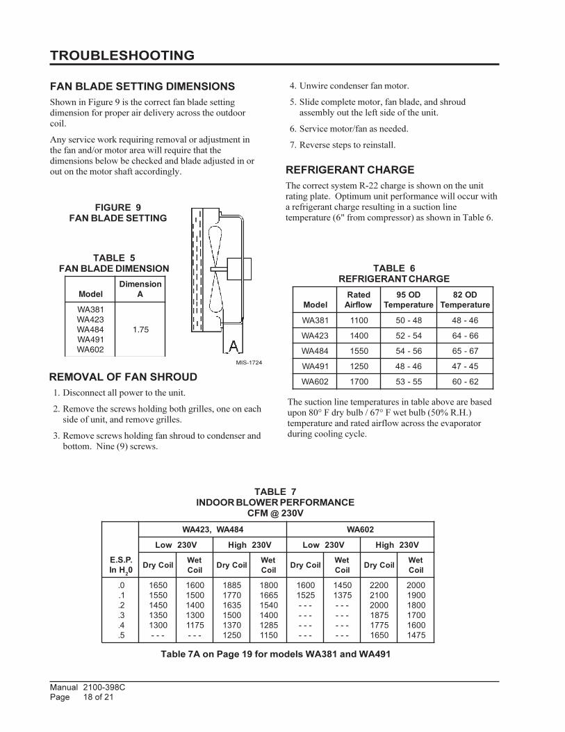
Manual 2100-398CPage 18 of 21
REMOVAL OF FAN SHROUD
1. Disconnect all power to the unit.
2. Remove the screws holding both grilles, one on each
side of unit, and remove grilles.
3. Remove screws holding fan shroud to condenser and
bottom. Nine (9) screws.
FIGURE 9FAN BLADE SETTING
TROUBLESHOOTING
4. Unwire condenser fan motor.
5. Slide complete motor, fan blade, and shroud
assembly out the left side of the unit.
6. Service motor/fan as needed.
7. Reverse steps to reinstall.
REFRIGERANT CHARGE
The correct system R-22 charge is shown on the unit
rating plate. Optimum unit performance will occur with
a refrigerant charge resulting in a suction line
temperature (6" from compressor) as shown in Table 6.
Table 7A on Page 19 for models WA381 and WA491
TABLE 5FAN BLADE DIMENSION
ledoMnoisnemiD
A
183AW324AW484AW194AW206AW
57.1
The suction line temperatures in table above are based
upon 80° F dry bulb / 67° F wet bulb (50% R.H.)
temperature and rated airflow across the evaporator
during cooling cycle.
TABLE 6REFRIGERANT CHARGE
ledoMdetaRwolfriA
DO59erutarepmeT
DO28erutarepmeT
183AW 0011 84-05 64-84
324AW 0041 45-25 66-46
484AW 0551 65-45 76-56
194AW 0521 64-84 54-74
206AW 0071 55-35 26-06
TABLE 7INDOOR BLOWER PERFORMANCE
CFM @ 230V
.P.S.EHnI 20
484AW,324AW 206AW
V032woL V032hgiH V032woL V032hgiH
lioCyrD teWlioC lioCyrD teW
lioC lioCyrD teWlioC lioCyrD teW
lioC
0.1.2.3.4.5.
05610551054105310031---
00610051004100315711---
588107715361005107310521
008156610451004158210511
00615251------------
05415731------------
002200120002578157710561
000200910081007100615741
FAN BLADE SETTING DIMENSIONS
Shown in Figure 9 is the correct fan blade setting
dimension for proper air delivery across the outdoor
coil.
Any service work requiring removal or adjustment in
the fan and/or motor area will require that the
dimensions below be checked and blade adjusted in or
out on the motor shaft accordingly.
MIS-1724

Manual 2100-398CPage 19 of 21
TABLE 9MAXIMUM ESP OF OPERATION
ELECTRIC HEAT ONLY
Values shown are for units equipped with standard
1-inch throwaway filter or 1-inch washable filter.
Derate ESP by .15 for 2-inch pleated filters.
ledoM 324AW 484AW 206AW
WKhgiHdeepS
woLdeepS
hgiHdeepS
woLdeepS
hgiHdeepS
woLdeepS
50A-01A-51A-02A-
05.05.05.05.
05.05.05.54.
05.05.05.05.
05.05.05.54.
05.05.05.05.
05.05.05.04.
00B-90B-51B-81B-
05.05.05.05.
05.05.05.05.
05.05.05.05.
05.05.05.05.
05.05.05.05.
05.05.05.05.
90C-51C-
05.05.
05.05.
05.05.
05.05.
05.05.
05.05.
TABLE 9AMAXIMUM ESP OF OPERATION
ELECTRIC HEAT ONLY
Values shown are for units equipped with
standard 1 inch throwaway filter or 1 inch
washable filter. Derate ESP by .15 for 2 inch
pleated filters.
ledoM 183AW 194AW
WKhgiHdeepS
deMdeepS
woLdeepS
hgiHdeepS
deMdeepS
50A-80A-01A-
03.03.03.
03.03.03.
03.03.02.
03.04.03.
03.04.03.
60B-90B-
04.04.
03.03.
03.03.
03.03.
03.03.
60C-90C-
03.03.
03.03.
03.03.
03.03.
03.03.
TABLE 8RECOMMENDED AIRFLOW
ledoMdetaR*MFC
detaR*PSE
dednemmoceRegnaRwolfriA
deepSyrotcaFnoitcennoC
183AW 0011 51. 058-0521 muideM
324AW 0041 03. 0511-0061 hgiH
484AW 0551 02. 5821-0571 hgiH
194AW 0521 02. 0011-5741 hgiH
206AW 0071 03. 5731-0591 hgiH
TABLE 7AINDOOR BLOWER PERFORMANCE
CFM @ 230V / 460V
.P.S.EnIH2O
183AW 194AW
deepShgiH deepSmuideM deepSwoL deepShgiH deepSmuideM
yrDlioC
teWlioC
yrDlioC
teWlioC
yrDlioC
teWlioC
yrDlioC
teWlioC
yrDlioC
teWlioC
0.1.2.3.
5261574105310511
574105310511528
524152310021---
52310021521578
521100110001---
00110001058---
0071055100410521
0551004105210011
5741573105210011
573105210011---

Manual 2100-398CPage 20 of 21
Low side pressure ± 2 PSIG
High side pressure ± 5 PSIG
Tables are based upon rated CFM (airflow) across the evaporator coil. If there is any doubt as to correct
operating charge being in the system, the charge should be removed, system evacuated and recharged
to serial plate instructions.
NOTE: Pressure table based on high speed condenser fan operation. If condensing pressures
appear elevated check condenser fan wiring. See “Condenser Fan Operation” on Page 16.
TABLE 10PRESSURE TABLE
COOLINGAir Temperature Entering Outdoor Coil °F
ledoMriAnruteRerutarepmeT
erusserP 57 08 58 09 59 001 501 011 511
183AW
BD.ged57BW.ged26
ediSwoLediShgiH
47571
47781
57202
67612
87232
97942
97562
08482
18203
BD.ged08BW.ged76
ediSwoLediShgiH
97971
97291
08702
18222
38832
48552
58272
68192
78013
BD.ged58BW.ged27
ediSwoLediShgiH
28581
28991
38412
48032
68642
78462
88252
98103
09123
324AW
BD.ged57BW.ged26
ediSwoLediShgiH
07702
27022
37532
57152
67662
77382
87003
97813
97733
BD.ged08BW.ged76
ediSwoLediShgiH
57212
77622
87142
08752
18372
28092
38803
48623
58643
BD.ged58BW.ged27
ediSwoLediShgiH
87912
08432
18942
38662
48382
58003
68913
78733
88853
484AW
BD.ged57BW.ged26
ediSwoLediShgiH
37402
47712
67232
87842
97562
08482
28403
38523
48843
BD.ged08BW.ged76
ediSwoLediShgiH
87012
97322
18832
28452
48272
68192
78213
98433
09753
BD.ged58BW.ged27
ediSwoLediShgiH
48712
58132
78742
88462
09282
29203
39323
59543
79963
194AW
BD.ged57BW.ged26
ediSwoLediShgiH
07991
17312
17722
27442
37062
57972
67892
77023
97143
BD.ged08BW.ged76
ediSwoLediShgiH
57402
67812
67332
77052
87762
08682
18603
28823
48053
BD.ged58BW.ged27
ediSwoLediShgiH
87112
97622
97142
08952
18672
38692
48713
58933
78263
206AW
BD.ged57BW.ged26
ediSwoLediShgiH
17332
27742
47262
57872
67592
77313
87133
87153
97173
BD.ged08BW.ged76
ediSwoLediShgiH
67732
87352
97962
08582
18303
28123
38043
48093
58183
BD.ged58BW.ged27
ediSwoLediShgiH
48542
58162
58872
68692
78413
88333
98353
09373
19493

Manual 2100-398CPage 21 of 21
TABLE 11OPTIONAL ACCESSORIES
WA381-A
WA381-B
WA381-C
WA423-A
WA423-B
WA423-C
WA484-A
WA484-B
WA484-C
WA491-A
WA491-B
WA491-C
WA602-A
WA602-B
WA602-C
traPrebmuN noitpircseD
50A-50AWHE80A-50AWHE01A-50AWHE51A-50AWHE
segakcaPretaeHsegakcaPretaeHsegakcaPretaeHsegakcaPretaeH
XXXX
XXXX
XXXX
50A-83AWHE80A-83AWHE01A-83AWHE50A-94AWHE
segakcaPretaeHsegakcaPretaeHsegakcaPretaeHsegakcaPretaeH
XXX
XX
X
90B-50AWHE51B-50AWHE81B-50AWHE
segakcaPretaeHsegakcaPretaeHsegakcaPretaeH
XXX
XXX
XXX
60B-83AWHE90B-83AWHE60B-94AWHE
segakcaPretaeHsegakcaPretaeHsegakcaPretaeH
XX
X
A90C-50AWHE51C-50AWHE
segakcaPretaeHsegakcaPretaeH
X XX
XX
X XX
60C-83AWHE segakcaPretaeH X X
5-POB5-DAFB5-DAFM
etalPffOknalBrepmaDriAhserFcirtemoraBrepmaDriAhserFdezirotoM
XXX
XXX
XXX
XXX
XXX
XXX
XXX
XXX
XXX
XXX
XXX
XXX
XXX
XXX
XXX
5-VRC5-MFIE
B5A-VREWB5C-VREW
tsuahxEhtiwrotalitneVlaicremmoCtsuahxEhtiwrezimonocErotalitneVyrevoceRygrenErotalitneVyrevoceRygrenE
XXX
XXX
XX
X
XXX
XXX
XX
X
XXX
XXX
XX
X
XXX
XXX
XX
X
XXX
XXX
XX
X
6-AMC01-AMC
)CAL(lortnoCtneibmAwoLRDT+CPH+CPL
X X X XX
XX
XX
X X X X X X X X
31-AMC51-CMC61-AMC81-AMC
CAL+RDT+CPH+CPLtiKtratS
lortnoCeusserPwoLCAL+CPL
XXX
XX
XX
XX
XXXX
XX
XX
XXX
XX
XX
XXX
XX
X
B50-BCMWC10-DCMWA80-BCMWA90-BCMWB70-BCMWA50-BCMWB40-BCMWB60-BCMW
tiKrekaerBtiucriCtiKtcennocsiDlluP
rekaerBtiucriCrekaerBtiucriCrekaerBtiucriCrekaerBtiucriCrekaerBtiucriCrekaerBtiucriC
XX
XX
XX
X
XX
X
X
X
X
X
X

Manual 2110-452D
Page 1 of 14
General Notes
� Revised and/or additional pages maybe issued from time to time.
� A complete and current manualconsists of pages shown in thefollowing contents section.
Important
� Contact the installing and/or local Barddistributor for all parts requirements.Make sure you have the completemodel and serial number availablefrom the unit rating plates.
Contents
Description Page
Cabinet Components� Exploded View .......................... 2� Usage List ................................. 3� Usage List ................................. 4
Functional Components� Exploded View .......................... 5� Usage List ................................. 6� Usage List ................................. 7
Control Panel� Exploded View .......................... 8� Usage List ................................. 9� Usage List ................................ 10� Blank Page .............................. 11� Exploded View ......................... 12� Usage List ................................ 13
Blower Assembly� Exploded View ......................... 14� Usage List ................................ 14
WALL MOUNTED
PACKAGE
AIR CONDITIONER
Models: WA381 WA424D
WA423 WA485D
WA484 WA604D
WA491 WA602
REPLACEMENT
PARTS MANUAL
Manual: 2110-452D
Supersedes: 2110-452C
File: Tab 16
Date: 01-22-07
Bard Manufacturing Company, Inc.
Bryan, Ohio 43506
Since 1914...Moving ahead, just as planned.
© Copyright 2003

Manual 2110-452D
Page 2 of 14
CABINET COMPONENTS
This drawing is referenced in Tables on Pages 3 and 4

Manual 2110-452D
Page 3 of 14
CABINET COMPONENTS
WA
38
1-A
, B
WA
381-C
WA
423-A
,B,E
WA
423-C
,F
WA
42
4D
A, B
WA
424D
C
WA
484-A
,B,E
WA
48
4-C
, F
WA
485D
A,B
WA
485D
C
.oN.gwD rebmuNtraP noitpircseD
1 412X721S esaBrewoL X X X X X X X X X X
2 *-262-005S 1 ediStfeL X X X X X X X X X X
3 *-162-005S 1 ediSthgiR X X X X X X X X X X
4 890-805S kcaB X X X X X X X X X X
5 *-241-605S 1 poT X X X X X X X X X X
6 *-770-415S 1 tnorFreppU X X X X X X X X X X
7 *-422-255S 1 rooDecivreS X X X X X X X X X X
8 *-840-811 1 ellirGresnednoC X X X X X X X X X X
9 *-750-811 1 ellirGediS 2 2 2 2 2 2 2 2 2 2
01 852X125S noititraPresnednoC X X X X X X X X X X
11 201-321S naPniarD X X X X X X X X X X
21 612X121 noititraPrewolB X X X X X X X X X X
31lenaPlortnoC
ylbmessAdnagniwarDylbmessAlenaPlortnoCeeS
tsiLstraPX X X X X X X X X X
4141
411-231S171-231S
)rennI(revoClenaPlortnoC)rennI(revoClenaPlortnoC
XX
XX
XX
XX
XX
51 *-311-335S 1 )retuO(revoClenaPlortnoC X X X X X X X X X X
61 *-812-351S 1 rooDsseccAtcennocsiD X X X X X X X X X X
71 420-521 duorhSnaF X X X X X X X X X X
81 041-311 tekcarBgnitnuoMmottoB X X X X X X X X X X
91 902-731 lliF X X X X X X X X X X
02 5-DAFB ylbmessArepmaDriAhserF X X X X X X X X X X
22 990X131 yarTretliF X X X X X X X X X X
32 778X501 troppuSediStfeL X X X X X X X X X X
42 640-741 troppuSrotaropavEtfeL X X X X X X X X X X
52 821-531 yawecaR X X X X X X X X X X
62 430X111S ylbmessAemarFriAteltuO X X X X X X X X X X
72 878X501 troppuSediSthgiR X X X X X X X X X X
82 *-240-341S 1 )retuO(etalPrevoCediSthgiR X X X X X X X X X X
92 921-531 dleihStaeH X X X X X X X X X X
03 *-051-311 1 gnihsalFniaRpoT X X X X X X X X X X
13 852-635S etalPffOkcolBnoititraP.dnoC X X X X X X X X X X
1 EXterior cabinet parts are manufactured with various paint color options. To insure that you receive the proper paint color,
you must include the complete model and serial number of the unit for which cabinet parts are being ordered.
This Table is references drawing on Page 2
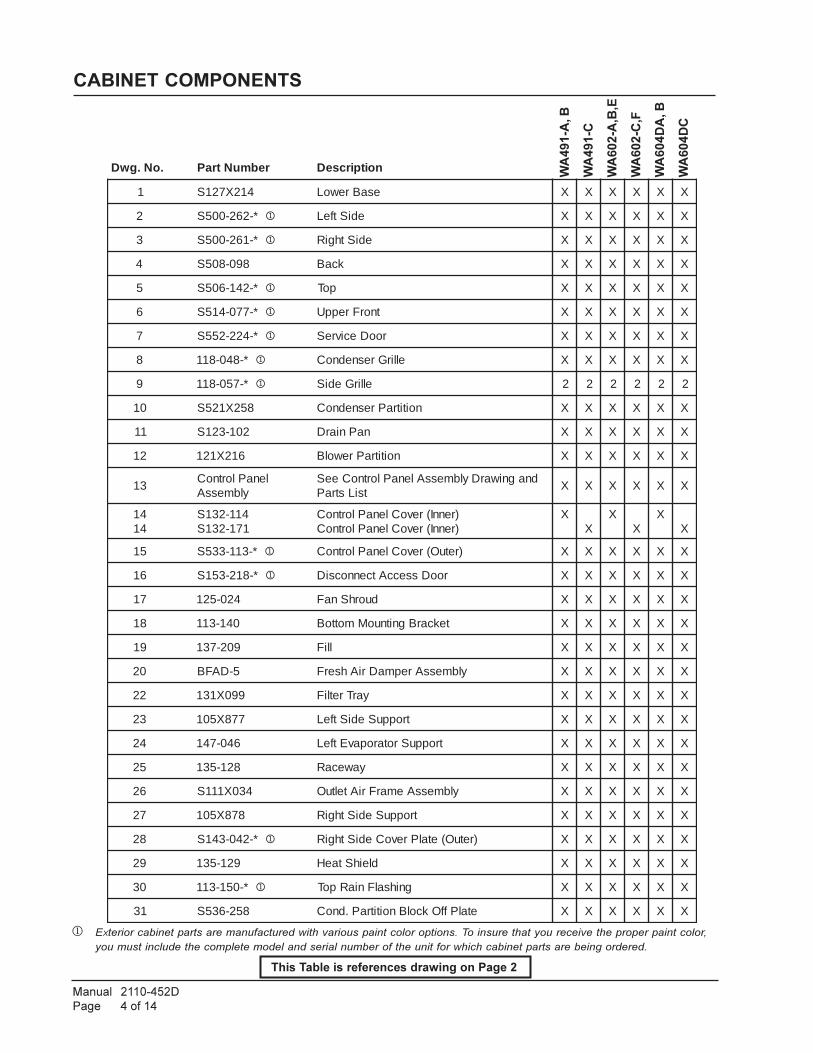
Manual 2110-452D
Page 4 of 14
WA
49
1-A
, B
WA
491-C
WA
602-A
,B,E
WA
602-C
,F
WA
60
4D
A, B
WA
604D
C
CABINET COMPONENTS
.oN.gwD rebmuNtraP noitpircseD
1 412X721S esaBrewoL X X X X X X
2 *-262-005S 1 ediStfeL X X X X X X
3 *-162-005S 1 ediSthgiR X X X X X X
4 890-805S kcaB X X X X X X
5 *-241-605S 1 poT X X X X X X
6 *-770-415S 1 tnorFreppU X X X X X X
7 *-422-255S 1 rooDecivreS X X X X X X
8 *-840-811 1 ellirGresnednoC X X X X X X
9 *-750-811 1 ellirGediS 2 2 2 2 2 2
01 852X125S noititraPresnednoC X X X X X X
11 201-321S naPniarD X X X X X X
21 612X121 noititraPrewolB X X X X X X
31lenaPlortnoC
ylbmessAdnagniwarDylbmessAlenaPlortnoCeeS
tsiLstraPX X X X X X
4141
411-231S171-231S
)rennI(revoClenaPlortnoC)rennI(revoClenaPlortnoC
XX
XX
XX
51 *-311-335S 1 )retuO(revoClenaPlortnoC X X X X X X
61 *-812-351S 1 rooDsseccAtcennocsiD X X X X X X
71 420-521 duorhSnaF X X X X X X
81 041-311 tekcarBgnitnuoMmottoB X X X X X X
91 902-731 lliF X X X X X X
02 5-DAFB ylbmessArepmaDriAhserF X X X X X X
22 990X131 yarTretliF X X X X X X
32 778X501 troppuSediStfeL X X X X X X
42 640-741 troppuSrotaropavEtfeL X X X X X X
52 821-531 yawecaR X X X X X X
62 430X111S ylbmessAemarFriAteltuO X X X X X X
72 878X501 troppuSediSthgiR X X X X X X
82 *-240-341S 1 )retuO(etalPrevoCediSthgiR X X X X X X
92 921-531 dleihStaeH X X X X X X
03 *-051-311 1 gnihsalFniaRpoT X X X X X X
13 852-635S etalPffOkcolBnoititraP.dnoC X X X X X X
This Table is references drawing on Page 2
1 EXterior cabinet parts are manufactured with various paint color options. To insure that you receive the proper paint color,
you must include the complete model and serial number of the unit for which cabinet parts are being ordered.
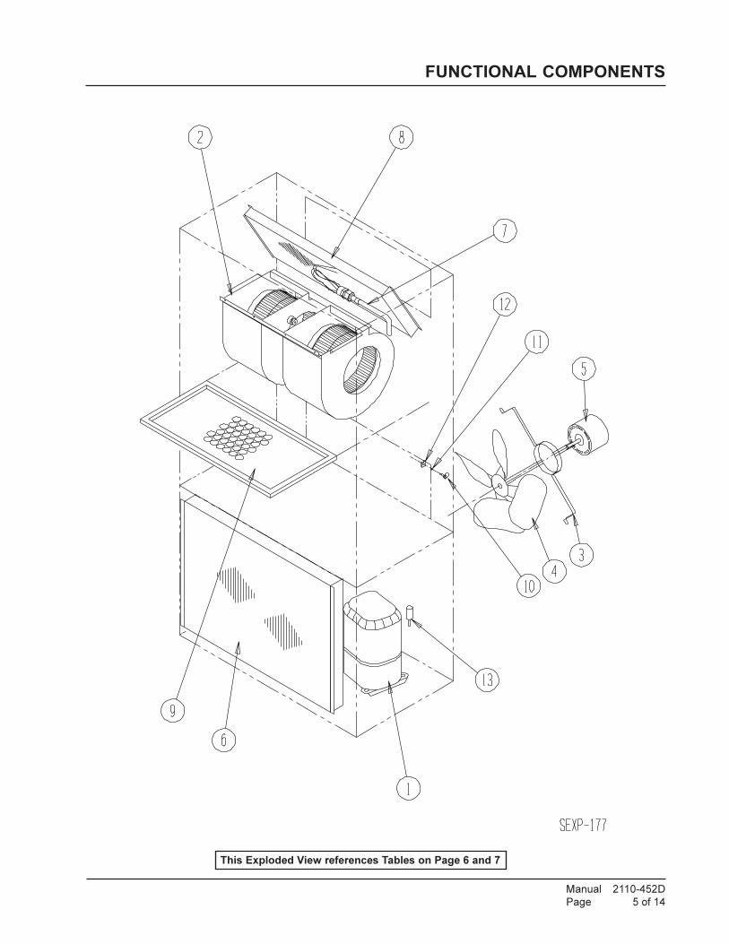
Manual 2110-452D
Page 5 of 14
FUNCTIONAL COMPONENTS
This Exploded View references Tables on Page 6 and 7
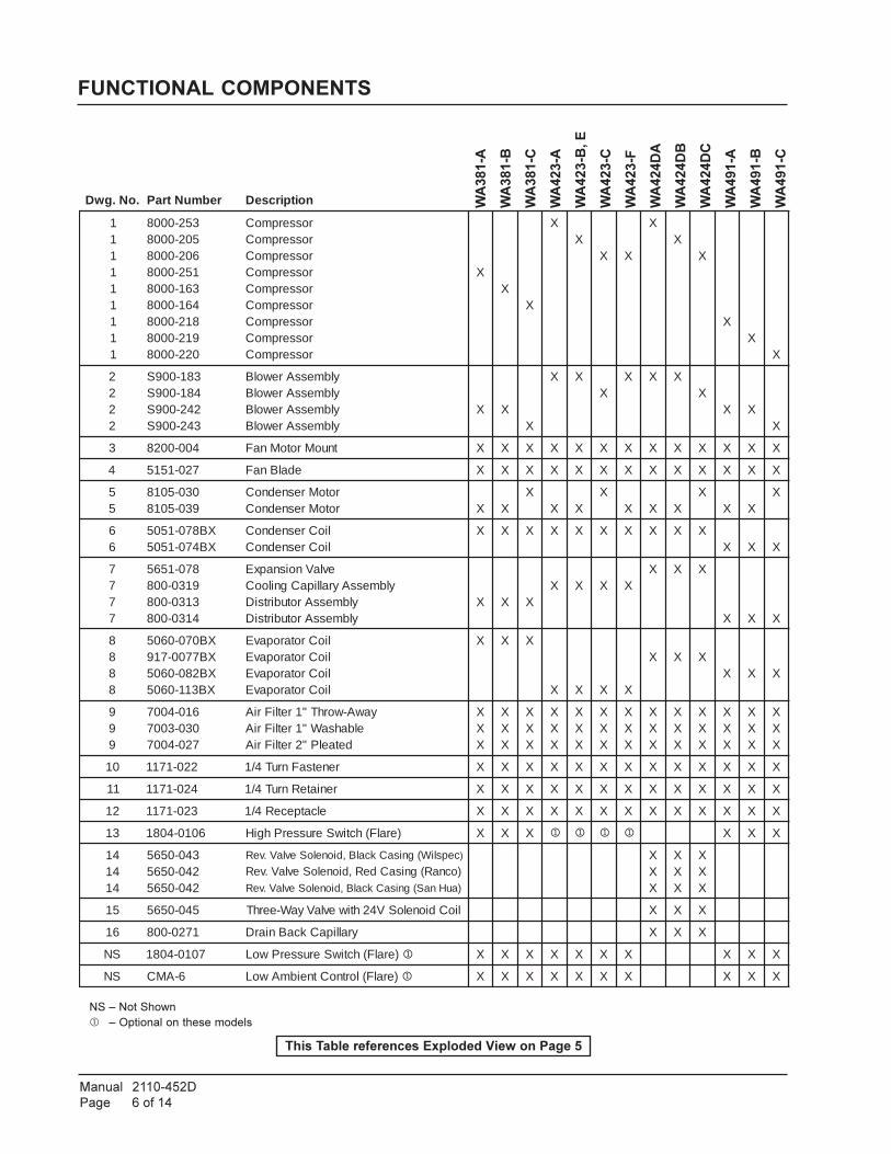
Manual 2110-452D
Page 6 of 14
NS – Not Shown
� – Optional on these models
WA
381-A
WA
381-B
WA
381-C
WA
423-A
WA
42
3-B
, E
WA
423-C
WA
423-F
WA
424D
A
WA
424D
B
WA
424D
C
WA
491-A
WA
491-B
WA
491-C
.oN.gwD rebmuNtraP noitpircseD
111111111
352-0008502-0008602-0008152-0008361-0008461-0008812-0008912-0008022-0008
rosserpmoCrosserpmoCrosserpmoCrosserpmoCrosserpmoCrosserpmoCrosserpmoCrosserpmoCrosserpmoC
XX
X
XX
X X
XX
X
XX
X
2222
381-009S481-009S242-009S342-009S
ylbmessArewolBylbmessArewolBylbmessArewolBylbmessArewolB
X XX
X XX
X X XX
X XX
3 400-0028 tnuoMrotoMnaF X X X X X X X X X X X X X
4 720-1515 edalBnaF X X X X X X X X X X X X X
55
030-5018930-5018
rotoMresnednoCrotoMresnednoC X X
XX X
XX X X
XX X
X
66
XB870-1505XB470-1505
lioCresnednoClioCresnednoC
X X X X X X X X X XX X X
7777
870-15659130-0083130-0084130-008
evlaVnoisnapxEylbmessAyrallipaCgnilooC
ylbmessArotubirtsiDylbmessArotubirtsiD
X X XX X X X
X X X
X X X
8888
XB070-0605XB7700-719XB280-0605XB311-0605
lioCrotaropavElioCrotaropavElioCrotaropavElioCrotaropavE
X X X
X X X X
X X XX X X
999
610-4007030-3007720-4007
yawA-worhT"1retliFriAelbahsaW"1retliFriA
detaelP"2retliFriA
XXX
XXX
XXX
XXX
XXX
XXX
XXX
XXX
XXX
XXX
XXX
XXX
XXX
01 220-1711 renetsaFnruT4/1 X X X X X X X X X X X X X
11 420-1711 reniateRnruT4/1 X X X X X X X X X X X X X
21 320-1711 elcatpeceR4/1 X X X X X X X X X X X X X
31 6010-4081 )eralF(hctiwSerusserPhgiH X X X 1 1 1 1 X X X
414141
340-0565240-0565240-0565
cepsliW(gnisaCkcalB,dioneloSevlaV.veR )
)ocnaR(gnisaCdeR,dioneloSevlaV.veR)auHnaS(gnisaCkcalB,dioneloSevlaV.veR
XXX
XXX
XXX
51 540-0565 lioCdioneloSV42htiwevlaVyaW-eerhT X X X
61 1720-008 yrallipaCkcaBniarD X X X
SN 7010-4081 )eralF(hctiwSerusserPwoL 1 X X X X X X X X X X
SN 6-AMC )eralF(lortnoCtneibmAwoL 1 X X X X X X X X X X
FUNCTIONAL COMPONENTS
This Table references Exploded View on Page 5

Manual 2110-452D
Page 7 of 14
FUNCTIONAL COMPONENTS
WA
484-A
WA
484-B
,E
WA
484-C
WA
484-F
WA
485D
A
WA
485D
B
WA
485D
C
WA
602-A
WA
602-B
,E
WA
602-C
WA
602-F
WA
604D
A
WA
604D
B
WA
604D
C
.oN.gwD rebmuNtraP noitpircseD
111111
351-0008451-0008551-0008632-0008122-0008222-0008
rosserpmoCrosserpmoCrosserpmoCrosserpmoCrosserpmoCrosserpmoC
XX
X X
XX
X
XX
X X
XX
X
2222
381-009S481-009S581-009S681-009S
ylbmessArewolBylbmessArewolBylbmessArewolBylbmessArewolB
X XX
X X XX
X XX
X X XX
3 400-0028 tnuoMrotoMnaF X X X X X X X X X X X X X X
4 720-1515 edalBnaF X X X X X X X X X X X X X X
55
030-5018930-5018
rotoMresnednoCrotoMresnednoC X X
XX X X
XX X
XX X X
X
6 XB470-1505 lioCresnednoC X X X X X X X X X X X X X X
77777
870-1565970-15654020-0089020-0084320-008
evlaVnoisnapxEevlaVnoisnapxE
ylbmessAyrallipaCgnilooC)59MerofebN/S(.yssA.paC.looC
)59MgnitratsN/S(ylbmessArotubirtsiD
X X X X
X X X
XX
XX
XX
XX
X X X
88888
XB070-0605XB170-0605XB280-0605XB2400-719XB4400-719
lioCrotaropavE)59MerofebN/S(lioCrotaropavE)59MgnitratsN/S(lioCrotaropavE
lioCrotaropavElioCrotaropavE
X X X X
X X X
XX
XX
XX
XX
X X X
999
610-4007030-3007720-4007
yawA-worhT"1retliFriAelbahsaW"1retliFriA
detaelP"2retliFriA
XXX
XXX
XXX
XXX
XXX
XXX
XXX
XXX
XXX
XXX
XXX
XXX
XXX
XXX
01 220-1711 renetsaFnruT4/1 X X X X X X X X X X X X X X
11 420-1711 reniateRnruT4/1 X X X X X X X X X X X X X X
31 6010-4081 )eralF(hctiwSerusserPhgiH 1 X X X X X X X X X X X X X X
414141
340-0565240-0565640-0565
)cepsliW(gnisaCkcalB,dioneloSevlaV.veR
)ocnaR(gnisaCdeR,dioneloSevlaV.veR)auHnaS(gnisaCkcalB,dioneloSevlaV.veR
XXX
XXX
XXX
XXX
XXX
XXX
51 540-0565 lioCdioneloSV42htiwevlaVyaW-eerhT X X X X X X
61 2720-008 yrallipaCkcaBniarD X X X X X X
SN 6-AMC )eralF(lortnoCtneibmAwoL 1 X X X X X X X X
SN 7010-4081 )eralF(hctiwSerusserPwoL 1 X X X X X X X X
NS – Not Shown
� – Optional on these models
This Table references Exploded View on Page 5

Manual 2110-452D
Page 8 of 14
CONTROL PANEL
This drawing is referenced in Tables on Pages 9 and 10

Manual 2110-452D
Page 9 of 14
CONTROL PANEL
� Optional on these models.
� Circuit breakers listed are for units without electric heat "0Z" models. Hot gas bypass models not
available without electric heat. See Heater Replacement Parts Manual for units with electric heat.
NS = Not shown
WA
381-A
WA
381-B
WA
381-C
WA
423-A
WA
423-B
WA
423-C
WA
423-E
WA
423-F
WA
484-A
WA
484-B
WA
484-C
WA
484-E
WA
484-F
.oNgniwarD .oNtraP noitpircseD
1 020-7068 pirtSlanimreTegatloVwoL X X X X X X X X X X X X X
222
310-7068410-7068510-7068
eloP2kcolBlanimreTeloP3kcolBlanimreT
rotalusnIcilonehP
XX X
X
XX X
XX
2 XX X
XX
2
33
650-1028230-1028
lortnoCrewolByaleRrewolB
X XX
X XX
X X X XX
X X
44
430-7048240-7048
remrofsnarTremrofsnarT
X XX
X XX
X X X XX
X X
55
200-1048520-1048
rotcatnoCrosserpmoCrotcatnoCrosserpmoC X
X XX
X X X XX
X X X X
6666
500-2558620-2558550-2558270-2558
roticapaCrotoMroodtuOroticapaCrotoMroodtuO
roticapaCrosserpmoCroticapaCrosserpmoC
X
XX
X
XX
X X
X
XX
X X
7 031-531 dleihSeriW X X X X X X X X X X X X X
8 600-1168 lanimreTdnuorG X X X X X X X X X X X X X
9 7101-0003 rotcennoCniP6 X X X X X X X X X X X X X
01 580-1028 rotinoMesahP X X X X X X X X X X
11 260-1028 yaleRmralA 1 X X X X X X X X X X X X X
21 400-1558 eciveDtratS X X X
31 880-1028 eludoMlortnoCrosserpmoC X X X 1 1 1 1 1 X X X X X
41 931X711 xoBegatloVwoL X X X X X X X X X X X X X
51 341X711 lenaPlortnoC X X X X X X X X X X X X X
61 710-7068 kcolBlanimreT 1 X X X X X X X X X X X X X
SNSNSNSNSN
830-5168040-5168240-5168250-5168
C10-DPMW
eloP2A53rekaerBtiucriC 2
eloP2A05rekaerBtiucriC 2
eloP3A53rekaerBtiucriC 2
eloP3A03rekaerBtiucriC 2
tcennocsiDlluP 2
X
XX
XX
X
X
X
XX
X
X
X
SNSNSNSNSNSNSNSNSNSN
731-5904821-5904432-5904722-5904922-5904832-5904123-5904813-5904326-5904136-5904
margaiDgniriWmargaiDgniriWmargaiDgniriWmargaiDgniriWmargaiDgniriWmargaiDgniriWmargaiDgniriWmargaiDgniriWmargaiDgniriWmargaiDgniriW
X
X
X
X
X
XX
X
X
X
X
X
X
This Table is references drawing on Page 8

Manual 2110-452D
Page 10 of 14
� Circuit breakers listed are for units without electric heat "0Z" models. Hot gas bypass models not
available without electric heat. See Heater Replacement Parts Manual for units with electric heat.
NS = Not shown
WA
491-A
WA
491-B
WA
491-C
WA
602-A
WA
602-B
WA
602-C
WA
602-E
WA
602-F
CONTROL PANEL
.oNgniwarD .oNtraP noitpircseD
1 020-7068 pirtSlanimreTegatloVwoL X X X X X X X X
222
310-7068410-7068510-7068
eloP2kcolBlanimreTeloP3kcolBlanimreT
rotalusnIcilonehP
XX X
X
XX X
XX
2
33
650-1028230-1028
lortnoCrewolByaleRrewolB
X XX
X XX
X X
44
430-7048240-7048
remrofsnarTremrofsnarT
X XX
X XX
X X
55
200-1048520-1048
rotcatnoCrosserpmoCrotcatnoCrosserpmoC X
X XX
X X X X
6666
500-2558620-2558950-2558850-2558
roticapaCrotoMroodtuOroticapaCrotoMroodtuO
roticapaCrosserpmoCroticapaCrosserpmoC
X
XX
X
XX
X X
7 031-531 dleihSeriW X X X X X X X X
8 600-1168 lanimreTdnuorG X X X X X X X X
9 7101-0003 rotcennoCniP6 X X X X X X X X
01 580-1028 rotinoMesahP X X X X X X
11 260-1028 yaleRmralA 1 X X X X X X X X
21 400-1558 )RCTP(eciveDtratS 1 X X
31 880-1028 eludoMlortnoCrosserpmoC X X X X X X X X
41 931X711 xoBegatloVwoL X X X X X X X X
51 341X711 lenaPlortnoC X X X X X X X X
61 710-7068 kcolBlanimreT 1 X X X X X X X X
SNSNSNSNSN
040-5168340-5168
C10-DPMW140-5168440-5168
eloP2A05rekaerBtiucriC 2
eloP3A04rekaerBtiucriC 2
tcennocsiDlluP 2
eloP2A06rekaerBtiucriC 2
eloP3A54rekaerBtiucriC 2
XX
XX
X
X
X
X
SNSNSNSNSN
821-5904722-5904922-5904813-5904326-5904
margaiDgniriWmargaiDgniriWmargaiDgniriWmargaiDgniriWmargaiDgniriW
XX
X
XX
X
XXX
XXXXX
This Table is references drawing on Page 8

Manual 2110-452D
Page 11 of 14
This page left blank
intentionally.

Manual 2110-452D
Page 12 of 14
CONTROL PANEL
2
6
11
4
7
15
8
10
17
14
93
1
165
SEXP-455
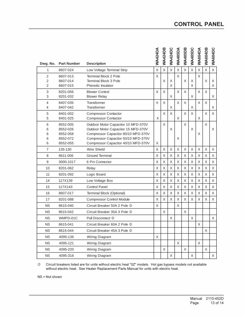
Manual 2110-452D
Page 13 of 14
WA424DA
WA424DB
WA424DC
WA485DA
WA485DB
WA485DC
WA604DA
WA604DB
WA604DC
CONTROL PANEL
� Circuit breakers listed are for units without electric heat "0Z" models. Hot gas bypass models not available
without electric heat. See Heater Replacement Parts Manual for units with electric heat.
NS = Not shown
.oN.gwD rebmuNtraP noitpircseD
1 420-7068 pirtSlanimreTegatloVwoL X X X X X X X X X
222
310-7068410-7068510-7068
eloP2kcolBlanimreTeloP3kcolBlanimreT
rotalusnIcilonehP
XX X
X
XX X
X
XX X
X
33
650-1028230-1028
lortnoCrewolByaleRrewolB
X XX
X XX
X XX
44
530-7048240-7048
remrofsnarTremrofsnarT
X XX
X XX
X XX
55
200-1048520-1048
rotcatnoCrosserpmoCrotcatnoCrosserpmoC X
X XX
X XX
X X
66666
500-2558620-2558850-2558270-2558550-2558
V073-DFM01roticapaCrotoMroodtuOV073-DFM51roticapaCrotoMroodtuOV073-DFM01/08roticapaCrosserpmoCV073-DFM01/05roticapaCrosserpmoCV073-DFM01/04roticapaCrosserpmoC X
XX
X
XX
X
XX
7 031-531 dleihSeriW X X X X X X X X X
8 600-1168 lanimreTdnuorG X X X X X X X X X
9 7101-0003 rotcennoCniP6 X X X X X X X X X
01 260-1028 yaleR X X X X X X X X X
11 290-1028 draoBcigoL X X X X X X X X X
41 931X711 xoBegatloVwoL X X X X X X X X X
51 341X711 lenaPlortnoC X X X X X X X X X
61 710-7068 )lanoitpO(kcolBlanimreT X X X X X X X X X
71 880-1028 eludoMlortnoCrosserpmoC X X X X X X X X X
SN 040-5168 eloP2A05rekaerBtiucriC 2 X X
SN 240-5168 eloP3A53rekaerBtiucriC 2 X X
SN C10-DPMW tcennocsiDlluP 2 X X X
SN 140-5168 eloP2A06rekaerBtiucriC 2 X
SN 440-5168 eloP3A54rekaerBtiucriC 2 X
SN 631-5904 margaiDgniriW X
SN 121-5904 margaiDgniriW X X
SN 022-5904 margaiDgniriW X X X
SN 613-5904 margaiDgniriW X X X
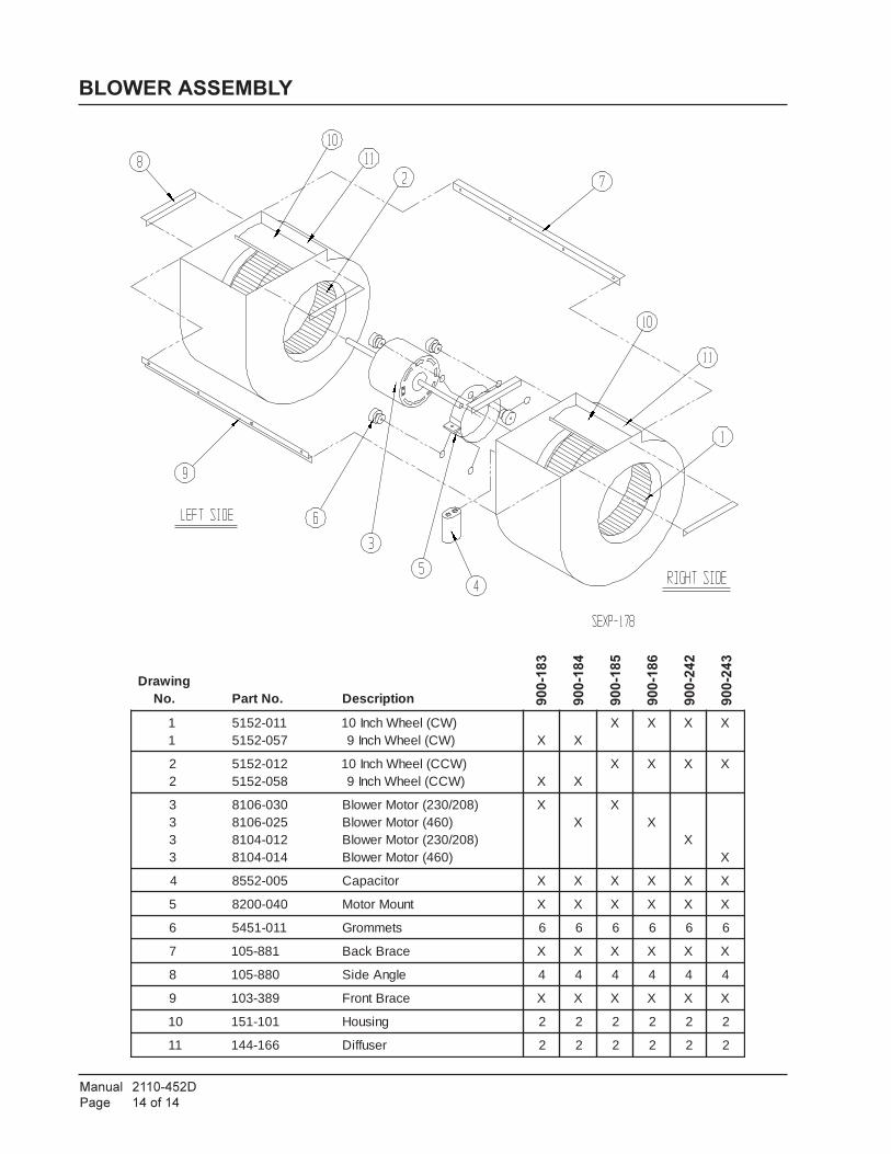
Manual 2110-452D
Page 14 of 14
BLOWER ASSEMBLY
900-183
900-184
900-185
900-186
900-242
900-243
gniwarD.oN .oNtraP noitpircseD
11
110-2515750-2515
)WC(leehWhcnI01)WC(leehWhcnI9 X X
X X X X
22
210-2515850-2515
)WCC(leehWhcnI01)WCC(leehWhcnI9 X X
X X X X
3333
030-6018520-6018210-4018410-4018
)802/032(rotoMrewolB)064(rotoMrewolB
)802/032(rotoMrewolB)064(rotoMrewolB
XX
XX
XX
4 500-2558 roticapaC X X X X X X
5 040-0028 tnuoMrotoM X X X X X X
6 110-1545 stemmorG 6 6 6 6 6 6
7 188-501 ecarBkcaB X X X X X X
8 088-501 elgnAediS 4 4 4 4 4 4
9 983-301 ecarBtnorF X X X X X X
01 101-151 gnisuoH 2 2 2 2 2 2
11 661-441 resuffiD 2 2 2 2 2 2


BARD MANUFACTURING CO., INC. — BRYAN, OHIO 43506Dependable quality equipment . . . since 1914
Limited Warranty
Limited Warranty To Original PurchaserBard Manufacturing Company, Inc. Bryan, Ohio 43506 warrants to you, the original purchaser, that your Bard product will be free from defects in
materials and workmanship when used under normal conditions from the installation date through the time periods outlined in the “Duration of Warranty”
section (see reverse side).
Proof Of PurchaseYou must be able to show us the date on which you purchased your product when you make a claim under this warranty. Your owner’s registration card
filed with us or your contractor’s invoice, bill of sale, or similar document is sufficient. If you can not show us the actual date of purchase, the time
periods in this warranty will start on the date that we shipped your Bard product from our factory.
What This Warranty Does Not Cover (Also see Duration of Warranty on reverse side)This warranty does not cover defects or damage caused by:
1. Alterations not approved by us; improper installation (including over or under sizing), improper repairs, or servicing; or improper parts and
accessories not supplied by us.
2. Misuse or failure to follow installation and operating instructions (including failure to perform preventative maintenance) or limitations on the rating
plate.
3. Operation in a corrosive atmosphere (such as acids, halogenated hydrocarbons or coastal environmental conditions).
4. Parts that must be replaced periodically (such as filters, oil nozzles, mist eliminators, WERV belts, pile seals, etc.).
5. Improper fuel or electrical supply (such as low voltage, voltage transients, and power interruption).
6. Accidents or other events beyond our reasonable control (such as storm, fire, or transportation damage).
7. Defects that happen after
(a) Anyone has tampered with the product.
(b) The product has been improperly serviced according to accepted trade practices;
(c) The product has been moved from its original place of installation; or,
(d) The product has been damaged by an event beyond Bard’s control (See also No. 5 above).
8. Consequential damages (such as increased living expenses while the product is being repaired). Some states do not allow the exclusion or
limitation of incidental or consequential damages, so the above limitation or exclusion may not apply to you.
9. This warranty does not cover units installed on over-the-road trucks, vans and trailers.
10. Cost of service call at installation site to diagnose causes of trouble, labor to replace defective component or transportation costs for
replacement parts.
11. Contact Bard Manufacturing Company, Inc. for specific warranty exclusions on products installed outside of the United States, Canada and Mexico.
Your ResponsibilitiesYou are responsible for
1. Preventative maintenance of the product (such as cleaning and replacement of filters, nozzles and other consumable parts).
2. Insuring that the instruction manual is followed for care and use of your product.
3. Insuring that your product is installed by a competent, qualified contractor, following all local and national codes, and industry standards.
What We Will Do About A DefectWe will either repair or replace the defective part only. Replacement parts may be reconditioned parts. The warranty for the repaired or replaced
part will last only for the remainder of the warranty period for the original part. For Heat Exchangers that are no longer available, we will give you credit
equal to the then current retail price of an equivalent Heat Exchanger.
Defective parts and a properly completed Bard parts warranty form must be returned to a Bard distributor to be eligible for a warranty credit or
replacement.
We will not pay or be responsible for labor or defective/replacement part transportation costs or delays in repairing or failures to complete repairs
caused by events beyond our reasonable control.
What You Must Do 1. Tell your heating and air conditioning contractor as soon as you discover a problem and have the contractor make repairs.
2. Pay for all transportation, related service labor, diagnostic charges, refrigerant, refrigerant recovery and related items.
ServiceIf your product requires service, you should contact the contractor who installed it or the contractor that has been providing the product’s
preventative maintenance and repair service. You may find the installing contractor’s name on the product or in your Owner’s packet. If you do
not know who that is, you should contact a competent, qualified contractor to make the repairs. If in doubt, you should contact the nearest distributor
that handles Bard products (see telephone pages). Please note that contractors and distributors that handle Bard products are independent contractors
and distributors, and therefore, are not under the direction of Bard Manufacturing Company, Inc.
Only WarrantyThis is the only warranty that we make. There are no other express warranties. All implied warranties are limited in duration to the duration of the
applicable written warranty made above.
Some states do not allow limitations on how long an implied warranty lasts, so the above limitation or exclusion may not apply to you.
Other RightsThis warranty gives you specific legal rights and you may have other rights which vary from state to state.
(For units applied within the United States, Canada and Mexico)
Form No. 7960-420
Issued: 05/10/06
Supersedes: 03/01/06

BARD MANUFACTURING CO., INC. — P.O. Box 607 — BRYAN, OHIO 43506
Dependable quality equipment . . . since 1914
Duration Of Warranty
Our warranty and all implied warranties are limited to defects arising during the periods shown in the following table:
FOR OWNERS INFORMATION
Product Model No. ________________________________________
Unit Serial No. ___________________________________________
Installation Date __________________________________________
Installing Contractor _______________________________________
Contractor Phone # _______________________________________
1 Heat transfer coils are covered for leaks for 5 years. Physical damage to coils resulting in leaks or insufficient airflow, or fin
deterioration due to corrosive atmosphere (such as acids, halogenated hydrocarbons or coastal environmental conditions) are not
covered.
2 Parts warranty is 1 year for all telecommunication, electric switch stations, pump stations and similar applications.
3 Limited lifetime warranty on Heat Exchangers applies to original purchaser in private, owner occupied residences. Subsequent
owners and commercial uses are warranted for 20 years from date of installation.
xiferPrebmuNledoM
---etaDnoitallatsnImorfsraeYforebmuN---
straPdnarosserpmoCslioCrefsnarTtaeH 1 regnahcxEtaeH
SRENOITIDNOCRIACQ,AQ,31AP,11P,01P,06LW-81LW,S5AW-S3AW,06AW-21AW
5 2 5 A/N
TC,27AW-07AW 1 5 A/N
SPMUPTAEHHW,HS,HC,WQ,HQ,31HP,11HP,01HP,VSG
5 5 A/N
CIRTCELE/SAGGW
5 5 01
SECANRUFLIOLF,HF,CF
5 A/N EMITEFIL 3
FOS 1 A/N 01
SEIROSSECCAsegakcapretaehdnanoitalitnevdellatsnidleiF/yrotcaF
5 A/N A/N
statsomrehT,statsidimuH,srellortnocSCT,04CET,0003CM ,aA0002SC detsiltonseirosseccadellatsnidleifrehtolladn
yletarapes1 A/N A/N
IMPORTANT - The Product Registration Card supplied with the product should be completed and mailed
immediately upon installation to assure maximum warranty coverage for your product.
Form No. 7960-420
Issued: 05/10/06
Supersedes: 03/01/06