Embed Size (px)
Citation preview
THE VARIED APPLICATIONS OF
DRILLING MACHINES
in relation to other production
by W. A. Hannaby, M.I.Prod.E.
Presented to the Halifax and Huddersfield Section of the Institution, 12th December, 1956.
IN presenting this Paper, I will endeavour to tracethe development of the drilling machine from its
early inception to the application of it today as ageneral purpose type of machine, as well as a semi-special and special machine covering the demands ofautomation. I will also give examples of actualinstallations in various types of factories.
It would, however, be as well, at the outset, todefine what is meant by drilling and where thisoperation ends and other subsequent operations begin.I would say, that in general, drilling could be definedas an operation of producing a hole from the solidmaterial, the maximum diameter now consideredeconomical for such an operation being in the regionof 3 in. Above this diameter, the process can betermed boring, or trepanning, where other cuttingmedia are used, such as boring bars, cutters, etc.
Design developments
However, I would first like to spend a short timereviewing the developments which have taken placein the design of the drilling machine since the daysof the very early radial and vertical types of machine.
It is, of course, common knowledge that theoperation of drilling a hole goes back to the earliestdays of mankind, when the drill consisted of a pieceof bone and the rotation was obtained by twistinga piece of hide in a bow-shaped instrument: thematerial being drilled was not, of course, metal.Interesting though these investigations into earlyhistorical periods may be, they would not yield anyinstructive information as far as present productionproblems are concerned.
I want, therefore, to commence round about theyear 1840, for it was in this period that we have thefirst records of a drilling machine, designed and built
by James Nasmyth, of Nasmyth & Gaskell, ofManchester. A model of this machine can be seen atthe Science Museum, London, to whom I am in-debted for the following information.
" The frame consists of a base with two columnssupporting a cross-girder, which carries the drillspindle and its driving and feed arrangements. Thepower is transmitted through mitre wheels to thedrill spindle, which is fed downwards by a centralscrew supported by a cross-head, carried on two smallwrought iron columns, this screw being fitted witha winch handle for feeding it downwards by hand.
" There is also an automatic feed given by avertical shaft that is intermittently rotated by a pawlworked by an eccentric on the lower end of thespindle sleeve."
This machine appears to be the very early fore-runner of the present-day cross rail drilling machine.In Hull Museum there is also a drilling machine builtby Whitworth in 1842.
The structure of the cross rail type machine, forthe benefit of those who are not cognisant of it, canbe described as a beam supported at each end byvertical supports, the drill saddle traversing along thebeam, whereas a radial drilling machine structure isa cantilever.
The drills themselves used during this period con-sisted of a rough bar of steel flattened in the smith'sforge and with an angular point forged at one end.These were known as ' spade' or ' diamond' drills.As can be imagined, these drills were very unsatis-factory, because if the holes were of any depth thedrills had to be constantly reground as carefully aspossible, in order to get them to run true.
However, due to the ingenuity of some person orpersons who, I believe, are unknown, a twist drill wasdeveloped, this being made by twisting a flat bar of
42
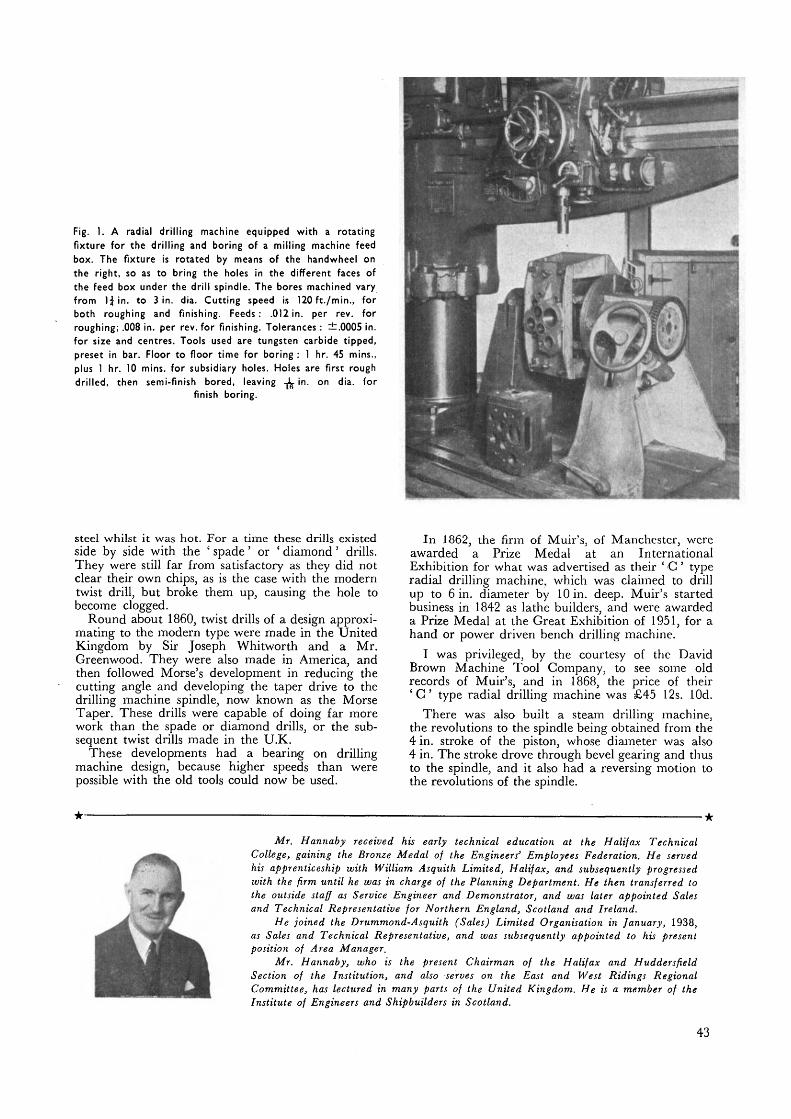
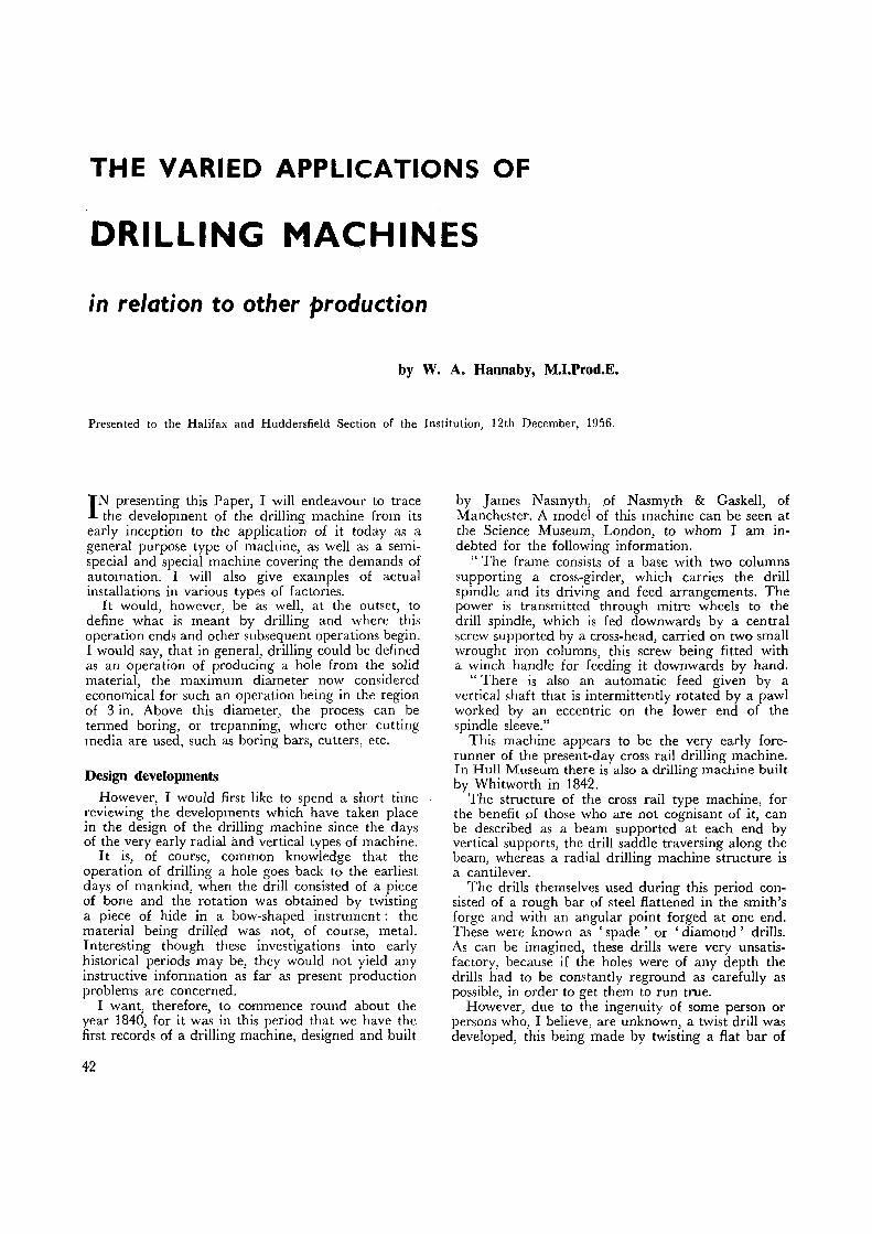
Fig. 1. A radial drilling machine equipped with a rotatingfixture for the drilling and boring of a milling machine feedbox. The fixture is rotated by means of the handwheel onthe right, so as to bring the holes in the different faces ofthe feed box under the drill spindle. The bores machined varyfrom 1| in. to 3 in. dia. Cutting speed is 120ft./min., forboth roughing and finishing. Feeds: .012 in. per rev. forroughing; .008 in. per rev. for finishing. Tolerances : ±.0005 in.for size and centres. Tools used are tungsten carbide tipped,preset in bar. Floor to floor time for boring : 1 hr. 45 mins.,plus 1 hr. 10 mins. for subsidiary holes. Holes are first roughdrilled, then semi-finish bored, leaving -1$ in. on dia. for
finish boring.
steel whilst it was hot. For a time these drills existedside by side with the ' spade' or ' diamond' drills.They were still far from satisfactory as they did notclear their own chips, as is the case with the moderntwist drill, but broke them up, causing the hole tobecome clogged.
Round about I860, twist drills of a design approxi-mating to the modern type were made in the UnitedKingdom by Sir Joseph Whitworth and a Mr.Greenwood. They were also made in America, andthen followed Morse's development in reducing thecutting angle and developing the taper drive to thedrilling machine spindle, now known as the MorseTaper. These drills were capable of doing far morework than the spade or diamond drills, or the sub-sequent twist drills made in the U.K.
These developments had a bearing on drillingmachine design, because higher speeds than werepossible with the old tools could now be used.
In 1862, the firm of Muir's, of Manchester, wereawarded a Prize Medal at an InternationalExhibition for what was advertised as their ' C ' typeradial drilling machine, which was claimed to drillup to 6 in. diameter by 10 in. deep. Muir's startedbusiness in 1842 as lathe builders, and were awardeda Prize Medal at the Great Exhibition of 1951, for ahand or power driven bench drilling machine.
I was privileged, by the courtesy of the DavidBrown Machine Tool Company, to see some oldrecords of Muir's, and in 1868, the price of their' C type radial drilling machine was £45 12s. lOd.
There was also built a steam drilling machine,the revolutions to the spindle being obtained from the4 in. stroke of the piston, whose diameter was also4 in. The stroke drove through bevel gearing and thusto the spindle, and it also had a reversing motion tothe revolutions of the spindle.
Mr. Hannaby received his early technical education at the Halifax TechnicalCollege, gaining the Bronze Medal of the Engineers' Employees Federation. He servedhis apprenticeship with William Asquith Limited, Halifax, and subsequently progressedwith the firm until he was in charge of the Planning Department. He then transferred tothe outside staff as Service Engineer and Demonstrator, and was later appointed Salesand Technical Representative for Northern England, Scotland and Ireland.
He joined the Drummond-Asquith (Sales) Limited Organisation in January, 1938,as Sales and Technical Representative, and was subsequently appointed to his presentposition of Area Manager.
Mr. Hannaby, who is the present Chairman of the Halifax and HuddersfieldSection of the Institution, and also serves on the East and West Ridings RegionalCommittee, has lectured in many parts of the United Kingdom. He is a member of theInstitute of Engineers and Shipbuilders in Scotland.
43
It was claimed that this machine would drill upto 1£ in. diameter from the solid, and open out toabout 3 in. diameter.
It is rather amusing to note that one of the claimsmade for this machine was that the foreman couldalways tell if it was working or not by observing thebeat of the exhaust!
These drills were used by Robey & Company, ofLincoln, on the erection of some large sugarmachinery; and also by Easton, Amos and Anderson,of Erith, who used compressed air in place of steam.There were, of course, a number of other well-knownbuilders of drilling machines during these periods,such as Shanks, Hetherington, Buckden, Tullis, andothers.
In 1865, some 90 years ago, William Asquith com-menced business in Halifax as a machine tool builderand, like most others, made all types of machines.In 1878, he produced his first drilling machine.
All these machines were of simple design, drivenby means of cone pulleys, with a very limited numberof speeds. As the materials used at that time wereunable to stand up to high speeds, the number ofrevolutions per minute was low, and the feed wasperformed mostly by hand. The drilling machine,however, continued to be considered, as in earlierdays, the cheapest means of producing a hole, andthe question of the accuracy of the hole was nevercontemplated on this type of machine. The further
operations on the bore in order to obtain accuracywere carried out on other machines, such as enginelathes.
These early types of machines continued in use formany years, and even up to 1905 the belt drive wasstill general, but a gear box and feed box had thenbeen incorporated, as higher speeds and feeds werenow found to be necessary for the application ofhigh speed twist drills.
Development of the electric motorThe development of the electric motor, both the
constant speed and particularly the variable speedelectric motor, constituted another step forward indesign. It was soon appreciated that by substitutinga motor for the pulleys by connecting, through areduction box, direct to the gear box (which due tothe use of a D.G. variable speed motor was consider-ably simplified) the machine could be installed in anydesired position without regard to the layout of theexisting line shaft. Also, the efficiency of the machinewas increased by the elimination of belt slip.
The drive, however, was still by means of theinternal vertical shaft, gearing, and thence by cross-shaft before reaching the spindle, and it meant thatthe radial drilling machine was still far from beingthe easy manipulative medium it is today.
Following this development came the mounting ofthe motor on the arm, and I believe William
Fig. 2. This illustrates a fine boring application using astandard radial drilling machine, the component being thespindle barrel of an O.D.I, drilling machine. The boring barwas mounted in a hardened steel bush rotating in phosphorbronze bushes, fitted with ball bearing thrust washers to takethe feed thrust. The boring bar was run at 1,200 r.p.m. with.002 in. feed. Material machined: phosphor bronze bushej.Tools: tungsten carbide (Jones & Calver C.F.). 2 in. dia.bearing, 5 in. long, IJ in. dia., bearing 3^ in. long. Metalremoved .014 in. dia., i.e. .007 in. per side. The twobearings were machined separately, cutting time being3.5 mins. approximately, and floor to floor time, 8 mins. Theovality of bores was within .0002 in., taper was .0001 in., andthere was no apparent out of line between the two boreswhen a bar was passed through them approximately .0002 in.down in diameter. The previous method of manufacture ofthese barrels was on an internal grinding machine whereeach end was ground separately. The time thus taken wasapproximately 40 mins. per barrel, and the surface finish inthe bronze was unsatisfactory and tended to give heat in the
running-in stages.
44

Fig. 3. This illustrates the use of a 6 ft. O.D.I radial as themedium for driving a nine-spindle multi-head attachment.The installation is at the works of Cockshutt Farm EquipmentLtd., of Brantford, Ontario, and it was entirely the firm'sidea to use such a set-up. The multi-head weighs 300 Ib. andhas nine spindles on a P.C.D. of 14 in. The diameter of holesto be drilled are $ in. and the component is a cast iron wheelhub for use on farming equipment. The quantities were such
that a special machine could not be justified.
Fig. 4. This is an exampleof the use of radials ontraverse beds and, in thiscase, shows two machinesmounted on one bed,demonstrating how differ-ent types of jobs can bemachined at the same set-up. Here, two machinescover the same area astwo or more much largerradius machines, placed
in fixed positions.
45

Fig. 5. A standard Asquith U.G.D. vertical drilling machinefitted with special indexing table and fixtures for, first, roughdrilling the little end and big end bores on Merlin engineconrods, and then boring out these bores to limits of .001 in.on centres. The bores were then finished on a fine boringmachine. This type of set-up is applicable when quantities do
not justify the cost of a special purpose machine.
Asquith's were the first to adopt this design, whicheliminated a considerable amount of shafting, gearing,etc., and thus gave higher efficiency to the drive.
The natural sequence to this was the design of amachine whereby the motor could be mounteddirectly on to the saddle. In the United Kingdomthe motor was so mounted about the 1920's, andspecially designed electrical gear was developed byBritish electrical motor manufacturers.
At the same time, special higher tensile strengthsteels became available for gears and shafts, andprocesses for hardening of gears became available.
The above factors enabled smaller members to beused which, in conjunction with the new type ofmotor that waV available, allowed for a completeassembly drive to be used inside a casing in con-junction with the drill spindle, which was now of a.more refined nature and smaller dimensions. Thus amore efficient slide became available, with consequenthigher ranges of speeds, and incorporating refine-ments to the spindle and spindle barrel design.
Simultaneously, refinements were being made tothe mounting of the arm on the pillar, to extend itsmanoeuvrability, and also improvements in lockingsystems, which resulted in the basis of the design as itis known today.
Multiple settingThis meant also that the radial drilling machine
became radial in the fullest sense, in that it could berotated through fully 360°. Arising from this develop-ment, far more use was made of what is now termedmultiple setting, i.e. the putting down of four baseplates instead of the customary one, so that jobscould be set up whilst others were being drilled.
This, however, could not be claimed as being dueto the development in the motor mounted on saddledesign; it really commenced when the electric motorwas first used as a direct drive mounted on the arm.Even when it was mounted on the floor, only threepositions were really available.
With the introduction of the direct drive machines,it soon became apparent that the stage had beenreached when the drilling machine .could no longerbe looked upon as a mere puncher of holes, and thatfar greater use could be made of it.
My first experience of using a radial drillingmachine for boring came in my early days as aService Engineer, when I was at the MorrisCommercial Company at Coventry. An AsquithO.D.I radial was being used for the boring of Morrisengine cylinder blocks; the boring bar being pilotedtop and bottom. Quite a good job was produced,but this, however, was only a roughing operation.
Use of tungsten carbideAs various types of cutting tools developed,
together with investigations into the use of tungstencarbide and improvements in jig and fixture design,it became apparent that the drilling machine, becauseit was, in the case of a radial, so easy to manipulateand had quite a good selection of speeds and feeds,could be used as a boring machine, provided that aflexible drive was used between the boring bar andthe drill spindle.
This was essential, because the radial arm is acantilever with a bending moment, and due to havingto compensate for the thrust of the cutting tool, itis deliberately designed with the arm, as we say,
-pointing down. Therefore, if a boring bar or anyother tool is inserted directly into the Morse Taperof the spindle end, it will be out of square in relationto the workpiece.
It is, therefore, essential to have the tool drivenin such a way that it can float and thus prevent anypull or drag taking place between the tool and thepilot bushes in the fixture. If accuracy is to be main-tained in the job to be produced, the pilot bushesmust be manufactured to close running tolerances,i.e. in the case of revolving bushes, this runningtolerance should be between the outer diameter ofthe bush and the inner diameter of the bore in thefixture, and in the case of a fixed bush and rotatingtool, between the outer diameter of the tool and theinner diameter of the bush.

Fig. 6. An example of the use of a portableUniversal drilling and tapping machine forthe drilling and tapping of holes round theinternal faces of a cylinder. This type ofmachine is of considerable use where holesmust be machined on large components andit is more advantageous to take the machine
to the job.
Fig. 7. A three-way multi-spindle machine for machining the cylinder head ofa diesel engine. This is a typical example of indexing table set-up withthree components being machined at the one setting, another beingremoved during the machining operations, and another loaded into the
fixture. This table is hand-operated.
47

Fig. 8. A rotary transfer type machine fordrilling, tapping, reaming and chamferingholes in a mtor car engine induction pipe.There are five stations, each having oneduplex fixture, which are arranged toaccommodate two components presentingalternatively the top and bottom faces of thecentre boss of the component. The com-ponents are located from two holespreviously drilled and reamed, and areclamped by means of an electrically-operatedchuck way. The table is power-indexed, asagainst the hand-indexing type, and isoperated by push buttons on the main controlpanel. When indexing, the weight of thetable and the fixtures is eased from its trackduring the rotation. The machine works toan automatic cycle of quick approach, feedand quick return to starting position.
(Cycle time : 40 sees.)
The bushes must also be designed to eliminate thepossibility of seizing-up, due to die presence of swarf,but this is not a difficult matter to overcome.
It should, however, be pointed out that as themachine is being used as a driving medium, theaccuracy of the work to be produced will dependon the accuracy to which the fixture and pilotingmedia are produced.
I would emphasise that although various boringoperations can be and are being carried out ondrilling machines, it is not claimed that this type ofmachine can replace the horizontal boring machine.Obviously, the size of the job which can be accom-modated and the question of facing limits its range.What I do claim is that many operations hithertoconsidered suitable only for elaborate and expensivemachines can, if properly planned and tooled up,be carried out on drilling machines. There is thegreat advantage that all the drilling and boringoperations within the range of the machine can becarried out on the same machine, instead of merelydoing the drilling, tapping and reaming on thedrilling machine, and then transporting the com-ponent or resetting on a boring machine.
It will be appreciated, from the description of theradial drilling machine, that the drill slide assemblyis a complete unit and, therefore, could be mountedon different types of structures.
There is the vertical type of machine, consisting ofthis unit mounted on a column and arranged with a
table to give a compound movement, so as to movethe workpiece quickly under the spindle centre. Thistype of structure is more rigid than the radial drillingmachine, but it is not as flexible in its operation.
If the workpiece is large, one or more of theseunits can be mounted on a crossrail, with a tableunderneath, this table being of either a static ortraversing type.
The drilling unit slide can also be modified so thatit is suitable for working in a horizontal direction,i.e. the horizontal drilling machine. With such amachine, a rotary table could be mounted in frontof the machine, which would enable machining to becarried out on four sides of the component at onesetting.
The foregoing types of machines are generally usedfor general engineering production where batchquantities are relatively small. Figs. 1-6 show a fewexamples of the use of standard type drillingmachines. After this stage, the quantity of productionof the component determines the character of thetype of machine which is required.
Under these conditions, machines carrying a groupof spindles arranged in a suitable pattern of holesto suit the component are used, and these are whatwe term multiple spindle drilling machines, on whichoperations of drilling, reaming, tapping, boring,counter-boring, recessing and chamfering, etc., can becarried out.
48
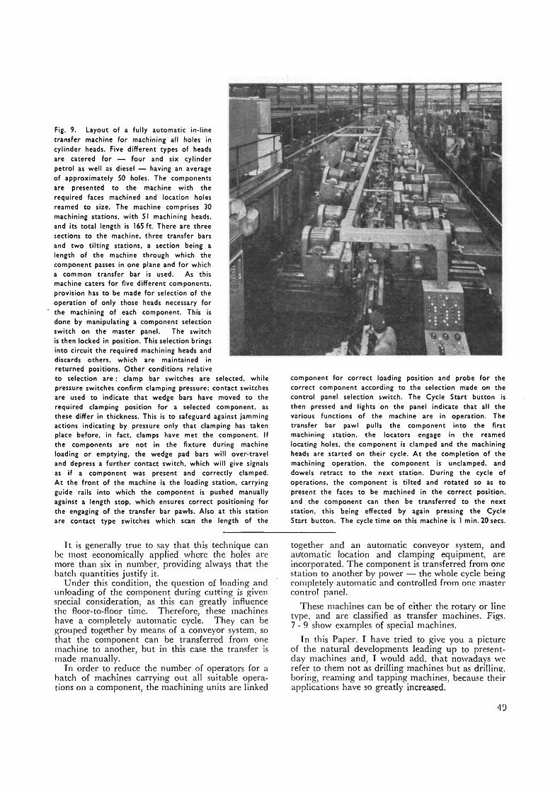
Pig. 9. La/out of a fully automatic in-linetransfer machine for machining all holes incylinder heads. Five different types of headsare catered for — four and six cylinderpetrol as well as diesel — having an averageof approximately 50 holes. The componentsare presented to the machine with therequired faces machined and location holesreamed to size. The machine comprises 30machining stations, with 51 machining heads,and its total length is 165 ft. There are threesections to the machine, three transfer barsand two tilting stations, a section being alength of the machine through which thecomponent passes in one plane and for whicha common transfer bar is used. As thismachine caters for five different components,provision has to be made for selection of theoperation of only those heads necessary forthe machining of each component. This isdone by manipulating a component selectionswitch on the master panel. The switchis then locked in position. This selection bringsinto circuit the required machining heads anddiscards others, which are maintained inreturned positions. Other conditions relativeto selection are: clamp bar switches are selected, whilepressure switches confirm clamping pressure; contact switchesare used to indicate that wedge bars have moved to therequired clamping position for a selected component, asthese differ in thickness. This is to safeguard against jammingactions indicating by pressure only that clamping has takenplace before, in fact, clamps have met the component. Ifthe components are not in the fixture during machineloading or emptying, the wedge pad bars will over-traveland depress a further contact switch, which will give signalsas if a component was present and correctly clamped.At the front of the machine is the loading station, carryingguide rails into which the component is pushed manuallyagainst a length stop, which ensures correct positioning forthe engaging of the transfer bar pawls. Also at this stationare contact type switches which scan the length of the
It is generally true to say that this technique canbe most economically applied where the holes aremore than six in number, providing always tha't thebatch quantities justify it.
Under this condition, the question of loading andunloading of the component during cut'ting is givenspecial consideration, as this can greatly influencethe floor-to-floor time. Therefore, these machineshave a completely automatic cycle. They can begrouped together by means of a conveyor system, sothat the component can be transferred from onemachine to another, but in this case the transfer ismade manually.
Tn order to reduce the number of operators for abatch of machines carrying out all suitable opera-tions on a component, the machining units are linked
component for correct loading position and probe for thecorrect component according to the selection made on thecontrol panel selection switch. The Cycle Start button isthen pressed and lights on the panel indicate that all thevarious functions of the machine are in operation. Thetransfer bar pawl pulls the component into the firstmachining station, the locators engage in the reamedlocating holes, the component is clamped and the machiningheads are started on their cycle. At the completion of themachining operation, the component is undamped, anddowels retract to the next station. During the cycle ofoperations, the component is tilted and rotated so as topresent the faces to be machined in the correct position,and the component can then be transferred to the nextstation, this being effected by again pressing the CycleStart button. The cycle time on this machine is 1 min.20secs.
together and an automatic conveyor system, andautomatic location and clamping equipment, areincorporated. The component is transferred from onestation to another by power — the whole cycle beingcompletely automatic and controlled from one mastercontrol panel.
These machines can be of either the rotary or linetype, and are classified as transfer machines. Figs.7 -9 show examples of special machines.
In this Paper. I have tried to give you a pictureof the natural developments leading up to present-day machines and, I would add, that nowadays werefer to them not as drilling machines but as drilling,boring, reaming and tapping machines, because theirapplications have so greatly increased.