Embed Size (px)
Citation preview

Drilling, Completion & Well Intervention and its relation to
Geology
Kjell Kåre Fjelde
A more detailed presentation on drilling & geology can be found on the resource CD Exercise related to the Festningen expedition Exercise related to the Storvola expedition

The different well phases • Drilling
– Make the wells • Completion
– Prepare the well for production – Different tools installed inside the well
• Production – Earn money
• Intervention – Fix well (damages or improve production)
• P & A – Plug the well

Drilling
• Main objective: – Drill a hole in the
ground as fast as possible without accidents
• Expensive – Rig rate – Rate of
penetration – Uforseen events – + +
West Phoenix – Dual ramrigg. Seadrill
www.nov.com - Rockforce www.nov.com
Must choose an appropriate drill bit depending on geology /formation hardness
Kymera Hybrid bit Baker Hughes Tools
www.nov.com

Casing program • The well will be drilled in sections. When
a section is drilled, a steel casing is set to protect the well before resuming drilling with a reduced hole size
Control pressures Case of unstable formations

Pressure Control • If Pwell < Ppore - > Potential kick • If Pwell > Pfrac - > Potential losses • i.e Ppore < Pwell < Pfrac
• Pwell (bar) = d x 0,0981 x Htvd
– d – density of mud i sg ( e.g 1500 kg/m3 =1.5sg)
– Htvd – True vertical depth of well • The different hole sections will
be drilled with different mud densities in order to control well pressures
• This will also affect the casing design
Figure to be found in drilling programs. The lithology column tells us what formations that will be drilled through. The curves shows us the pore and fracture pressures and the mudweight we should use in the different hole sections
E.g.here we use a mudweight of 1.45 sg = 1450 kg/m3

Bit Choice & ROP • ROP (rate of penetration) tells us how fast we drill.
– (1 m/ hour – very slow, 60 m / hour – quite good) • Low ROP - > Expensive operations. • ROP will depend on formation hardness & bit choice • Bit change (wear, failure etc) is time consuming & costs
money • Important to choose the right bit for the formation to
ensure – As high ROP as possible – Avoid wearing out the bits too early.
– Bit types: (Roller Cone, PDC, Hybrid bits and Diamond Bit)

Formation hardness
• The choice of an approriate bit will depend on formation hardness & abrasiveness – Soft/Medium soft formation
• Shale, clay, limestone, sands. – Medium hard/hard formation
• Hard limestone, sandstone, dolomite – Hard and abrasive formations
• Granites, basalts, quartzite and chert
• Check www.adriatech.com for appropriate rock bits for the different formation types.

Roller Cone • Steel tooth
– Top hole, Soft formations • Tungsten carbid inserts
– Medium to very hard formations
– Formations where PDC does not work
– Drill out shoe (cement) • Rate of penetration –
Medium, Slow • Steerability – Good • More trips to change bit
due to wear compared to using PDC bits.
www.nov.com - Rockforce
Be aware of: Cones can be lost (fishing operations) The cutters will be worn down Bearings is a weak point Gauge wear Bit balling (bit packed with formation)

PDC (fixed cutter bit) • Soft to medium hard formations
(not applicable in very hard & abrasive formations)
• Shales are easier to drill (ROP) than limestone/sandstone and PDC bits usually drills twice as fast in shale compared to roller cone
• Lower sections (12 ¼” hole ->) • Steerable and rotary applications
(motor & RSS) • High ROP (opposed to roller cones) • More expensive • More robust (fewer trips compared
to roller cone) • Steerability depends on design
Figure taken from Vett & Viten

Hybrid Bits (recent technology)
• Combination of roller cone and PDC bit design (use the best of both)
• Hard and interbedded formations - handles changes from soft to hard rock
• Less vibrations • Increased ROP potential • Chert drilling
Kymera Hybrid bit Baker Hughes Tools

Natural Diamond Bits • Applicable for hard
formations (e.g. where roller cone is too slow or har too short lifetime)
• Not applicable for chert and pyrite (will break into pieces and may destroy the diamonds)
• Not applicable for very hard broken formations (may break the diamonds) www.nov.com

Directional Drilling
• Directional drilling was a step change in development of oil & gas resources
• Better drainage – Eg. the Troll field
(exploit a wide but thin oil layer)
– Drain several layers
Hydro drilling for oil in Bergen

Directional drilling
• Avoid salt dome structures
• Faults or hard formations layers – Cross with
right angle • Multilaterals • Sidetracking

Drilling problems • Three major problems that can
occur during a drilling operation – Kick
• Inflow of gas/oil in the well during operation
• If not controlled, it can lead to a blowout
– Lost Circulation • Mud losses to formation • Expensive • Can lead to a kick
– Stuck pipe • If the drillstring is stuck, the worst
case scenario might be to plug and make a sidetrack
• Very expensive
Deepwater Horizon – 21 April 2010.- Gulf of Mexico, www.wikipedia.org

Kick • Kick - > unwanted inflow of gas, oil or water, if
not controlled - > Blowout • Reasons:
– Uncertainty in pore pressure – Too low mudweight – Swab (during tripping or heave effects) – Lost circulation (mud disappear) caused by
too high well pressures causing fractures or drilling into caves.
– Insufficient refill of well while tripping out.
Barrier drawing from NORSOK D010. It shows the BOP (blowout preventor) which is a classified as a secondary barrier element. It is closed in case of a kick. A well control procedure is initiated and the kick is circulated out of the well using the chokeline and choke.
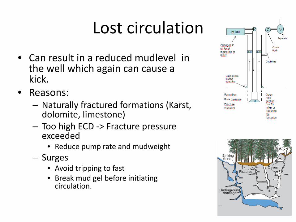
Lost circulation • Can result in a reduced mudlevel in
the well which again can cause a kick.
• Reasons: – Naturally fractured formations (Karst,
dolomite, limestone) – Too high ECD -> Fracture pressure
exceeded • Reduce pump rate and mudweight
– Surges • Avoid tripping to fast • Break mud gel before initiating
circulation.
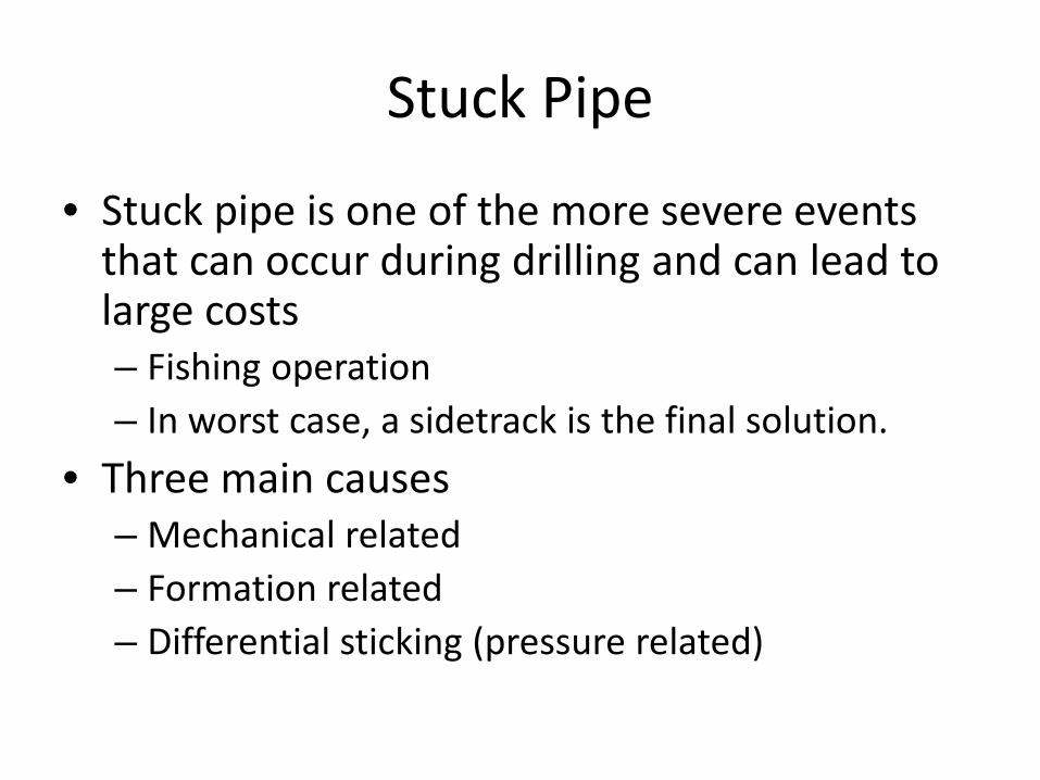
Stuck Pipe
• Stuck pipe is one of the more severe events that can occur during drilling and can lead to large costs – Fishing operation – In worst case, a sidetrack is the final solution.
• Three main causes – Mechanical related – Formation related – Differential sticking (pressure related)
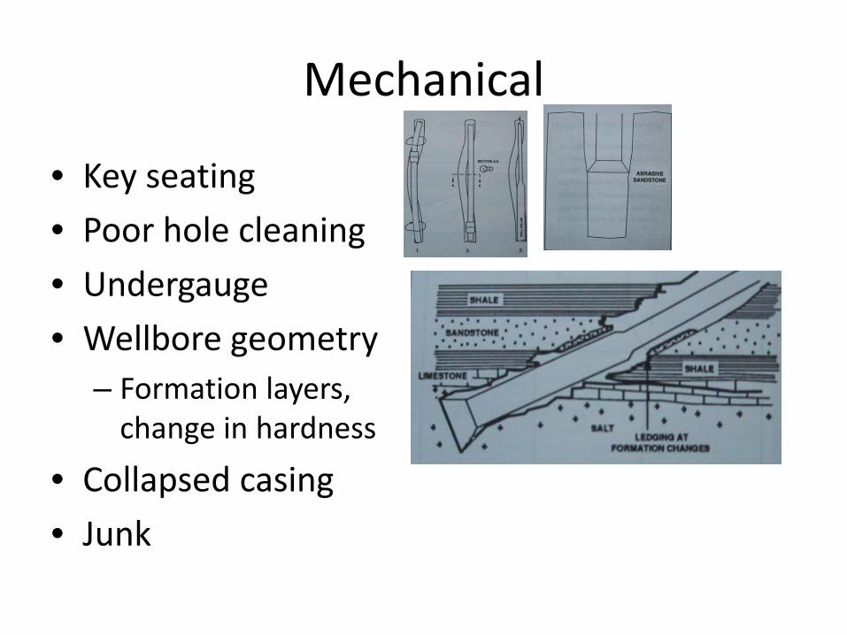
Mechanical
• Key seating • Poor hole cleaning • Undergauge • Wellbore geometry
– Formation layers, change in hardness
• Collapsed casing • Junk
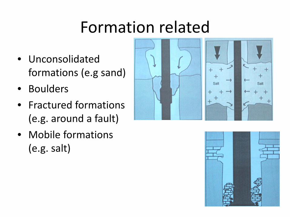
Formation related
• Unconsolidated formations (e.g sand)
• Boulders • Fractured formations
(e.g. around a fault) • Mobile formations
(e.g. salt)

Formation related - Shale
• Shale can cause som special problems: – Geo pressured shale
(over pressured shale) • Requires a higher
mudweight to control it.
– Reactive shale (water from mud inhibits the shale and it swells) – lack of inhibition

Completion • After the well has been drilled
it has to be completed and prepared for production
• A lot of equipment is installed in the well e.g.
– Production tubing – Production packer (fixes the
production tubing inside last set casing)
– Downhole safety valve (SCSSV) – Etc
• The reservoir has to be prepared for production
– Different solutions exists
Figure from NORSOKD010 showing the barrier elements in a production well

Two major types of completion
Figure from BakerHughes
Cased hole completion. Use of perforation guns
www.akersolutions.com
EXCLUDER2000 Screen (15-30%)
Open hole completion
Use of sandscreens to protect the well from eroding sand

Intelligent well completions
• In these wells one can install valves and control lines which can control the production from different zones in one well.
• Need less wells • Control water
production – Water production is
unwanted.

Intelligent well completions
• Using an intelligent well completion we can control the water production for instance by closing zones or by reducing water injection in zones where there is large water cut.
Well Intervention
• During the production phase there can be several reasons for performing a live well intervention operation: – Scale removal (salts forming in the well) – Azid stimulation (carbonates) – Removing sand/cleaning sand screens – Perform production logging to detect water producing
formations that should be sealed – +++
• Most common methods (wireline or coiled tubing)

Wireline
Often used in conjunction with tractor to intervene in inclined sections. - www.akersolutions.com

Wireline – example of application
• One example could be to intervene in the well to find which formation layers that are producing water
• One would need a braided (electric) wireline rig up, tractor and a production logging tool string.
www.akersolutions.com
The rotating speed will depend on which fluid that is present – Identify fluid type.
Fullbore & Inline spinner

Coiled Tubing
• Use of a flexible string that can be run in and out of the well and fluids can be circulated
• Used for instance for: – Azid stimulation
(carbonates) – Sand cleanouts (e.g long
horisontal wells with sand)/sandscreens
www.nov.com
www.slb.com

The different well phases • Drilling
– Make the wells • Completion
– Prepare the well for production – Different tools installed inside the well
• Production – Earn money
• Intervention – Fix well (damages or improve production)
• P & A – Plug the well