Embed Size (px)
Citation preview

Korean J. Chem. Eng., 25(6), 1252-1266 (2008)SHORT COMMUNICATION
1252
†To whom correspondence should be addressed.E-mail: [email protected]
The use of dilute acetic acid for butyl acetate production in a reactive distillation: Simulation and control studies
Amornchai Arpornwichanop*,†, Chantarawadee Wiwittanaporn*, Suthida Authayanun*,and Suttichai Assabumrungrat**
*Control and Systems Engineering, Department of Chemical Engineering, Faculty of Engineering,Chulalongkorn University, Bangkok 10330, Thailand
**Center of Excellence in Catalysis and Catalytic Reaction Engineering, Department of Chemical Engineering,Faculty of Engineering, Chulalongkorn University, Bangkok 10330, Thailand
(Received 24 December 2007 • accepted 21 April 2008)
Abstract−The recovery of dilute acetic acid, which is widely found as a by-product in many chemical and petrochemi-cal industries, becomes an important issue due to economic and environmental awareness. In general, separation ofacetic acid in aqueous solution by conventional distillation columns is difficult, requiring a column with many stagesand high energy consumption. As a result, the primary concern of the present study is the application of reactive distilla-tion as a potential alternative method to recover dilute acetic acid. The direct use of dilute acetic acid as reactant foresterification with butanol to produce butyl acetate in the reactive distillation is investigated. Simulation studies areperformed in order to investigate effect of the concentration of dilute acetic acid and key process parameters on theperformance of the reactive distillation in terms of acetic acid conversion and butyl acetate production. In addition,three alternative control strategies are studied for the closed loop control of the reactive distillation. The control ob-jective is to maintain the butyl acetate in a bottom product stream at the desired purity of 99.5 wt%.
Key words: Dilute Acetic Acid, Reactive Distillation, Butyl Acetate, Simulation, Control
INTRODUCTION
The aqueous solution of acetic acid is normally found as a by-product from many chemical and petrochemical processes. Exam-ples of such relevant processes include the production of celluloseacetate, an ester group of cellulose used in lacquers and the photo-graphic film process, which is typically associated with a 35 wt%aqueous solution of acetic acid as a waste stream. Other importantprocesses involve the synthesis of terephthalic acid and glyoxal,which have by-products of dilute acetic acid streams of typically70 wt% and 13-20 wt%, respectively [1,2].
Recovery of dilute acetic acid, therefore, becomes an importantissue due to economic and environmental awareness. The conven-tional process applied to separate acetic acid from its aqueous solu-tion involves a dehydration process by using a distillation column,and then the high-purity acetic acid obtained is used as a raw ma-terial in the synthesis of many valuable chemical compounds. Dueto the special properties of acetic acid, separation with distillation isdifficult and expensive, requiring a column with many stages andhigh energy consumption. An alternative process for acetic acid re-covery is an extraction by using a suitable solvent; however, it islimited by phase separation [1,3]. Furthermore, additional steps torecover and recycle the solvent are necessary.
Recently, a number of researches have been focused on the im-plementation of reactive distillation as a promising alternative torecover dilute acetic acid. In comparison with the traditional approachof separation followed by reaction processes, performing the chem-
ical reaction and separation in a single reactive distillation columnoffers advantages not only to separate acetic acid from its aqueoussolution but also to produce a valuable product at the same time,thereby reducing capital and energy costs. Following this approach,the direct utilization of dilute acetic acid as a reactant for the pro-duction of a high-valued ester, a common solvent used in chemicalindustries, has received much attention [2,4]. In general, the esteri-fication of acetic acid and different alcohols is represented by thefollowing reaction:
Acetic Acid+Alcohol⇔Acetate+Water (1)
Since the esterification reaction is equilibrium limited, the use ofthe reactive distillation is an attractive method by removing prod-ucts from the reaction mixture, which leads to an increase in thereactant conversion. In addition, it was reported that a ternary azeo-tropic mixture of acetate, alcohol and water is found [5,6], thus re-sulting in difficulties in downstream separation if a traditional pro-duction process is utilized. However, the reactive distillation maybe effective in order to deal with these difficulties.
Generally, the design and operation of reactive distillation sys-tems are considerably more complex than those of conventional re-actors or distillation. Nonlinear phenomena, which are caused byinteractions of reaction kinetics, phase equilibrium and mass trans-fer, and strong influences of various operating parameters, lead tothe complicated behavior of the systems [7]. Although a large num-ber of research efforts have been conducted to investigate anddesign reactive distillations with various systems [8-11], detaileddesign of reactive distillation for mixtures exhibiting phase-split be-havior in a decanter is less obvious. Another important issue to beconsidered for the successful application of reactive distillation col-

The use of dilute acetic acid for butyl acetate production in a reactive distillation: Simulation and control studies 1253
Korean J. Chem. Eng.(Vol. 25, No. 6)
umns to recover dilute acetic acid is the design of control systemsto maintain the columns at a desired condition. However, there islimited research concerning the closed-loop control of reactive dis-tillations [12]. For examples, Al-Arfaj and Luyben [13] evaluatedsix alternative control structures for an ideal two-product reactivedistillation column. In all the schemes, a composition analyzer wasused in the reactive zone to maintain stoichiometric balance. Wanget al. [14] studied a reactive distillation column for butyl acetateproduction from a pure acetic acid under steady-state condition anddesigned the control strategy of the column. Product quality wasmaintained by controlling the temperature of the stage inside thecolumn.
In this work, the implementation of a reactive distillation to re-cover dilute acetic acid via esterification with butanol for the pro-duction of butyl acetate, a relatively important solvent, is investigated.Simulation studies of the effect of dilute acetic acid concentrationon the reactive distillation performance in terms of acetic acid con-version and butyl acetate production are carried out by using HYSYScommercial software. The effects of key design and operating var-iables on the performance of the reactive distillation are also evalu-ated in order to determine an optimal configuration of the reactivedistillation column. Finally, the closed-loop control of the reactivedistillation column based on the obtained suitable column configu-ration and specifications is considered.
SIMULATION OF REACTIVE DISTILLATION
A steady-state simulation of a reactive distillation for the pro-duction of butyl acetate from esterification of dilute acetic acid andbutanol is performed by using HYSYS commercial software. Arigorous equilibrium stage model and NRTL model for describingthermodynamic properties and phase equilibriums are used [15,16].The configuration of a reactive distillation column under the studyis shown in Fig. 1. There are three zones in the column. The rectify-
Fig. 1. Configuration of a reactive distillation column for butyl ace-tate process.
Table 1. Specifications of reactive distillation column
Feed conditionsHOAc BuOH
Flow rate (kmol/h) 100 100Temperature (oC) 25 25Pressure (atm) 1.2 1.2
Column specificationsNumber of rectifying stages 11Numver of reactive stages 13Number of stripping stages 15Overhead pressure (atm) 1Column pressure drop (atm) 0.134
Table 2. Comparison of experimental data and simulation results
Experimentaldata [17]
Simulation results(HYSYS)
Bottom flow (mol/h) 42 41.9Distillate flow (mol/h) 27 27.1xB (HOAc) 0.171 0.172xB (BuOH) 0.287 0.298xB (BuOAc) 0.517 0.527xB (H2O) 0.025 0.003xD (HOAc) 0.143 0.1586xD (BuOH) 0 0xD (BuOAc) 0.008 0.0154xD (H2O) 0.849 0.826Reboiler duty (watt) 1070 950XBuOH (%) 64.58 64.31
Fig. 2. Effect of feed location at different acid concentrations.
ing and stripping zones operate exactly as a nonreactive distillationcolumn in order to purify top and bottom products, respectively.Butyl acetate (BuOAc) and water (H2O) are formed in the reactivezone where the esterification of acetic acid (HOAc) and butanol(BuOH) as in Eq. (2) occurs. The kinetic expressions of this reac-

1254 A. Arpornwichanop et al.
November, 2008
Fig. 4. Effect of the number of non-reactive stages at different acid concentrations.
Fig. 3. Effect of the number of reactive stages at different acid concentrations.

The use of dilute acetic acid for butyl acetate production in a reactive distillation: Simulation and control studies 1255
Korean J. Chem. Eng.(Vol. 25, No. 6)
tion in the presence of Amberlyst 15 as catalyst reported by Steini-geweg and Gmehling [17] are used in this study (Eqs. (3)-(5)).
(2)
(3)
(4)
(5)
The molar feed ratio of HOAc to BuOH is kept constant at 1 : 1following the stoichiometric ratio of the reaction. BuOH and HOAcfeeds are mixed in a single stream and then introduced to the col-umn at the same stage. The overhead vapor having a compositionclose to a ternary azeotropic mixture of H2O, BuOH, and BuOAcis condensed in a condenser and then separated into two phases ina decanter [5,6]. The aqueous phase is completely withdrawn fromthe decanter, whereas the organic phase is totally recycled back tothe column. BuOAc product is removed from the bottom of the col-umn as it is the highest boiling point component in the system. Thespecifications of the reactive distillation column at standard condi-
HOAc + BuOH BuOAc + H2OH+
r = kf aHOAcaBuOH − aBuOAcaH2O
Keq---------------------⎝ ⎠
⎛ ⎞
kf = 6.1084 104 − 56.67 kJ/mol
RT-------------------------------⎝ ⎠
⎛ ⎞exp×
Keq = 0.6206 − 10.99 kJ/mol
RT-------------------------------⎝ ⎠
⎛ ⎞exp
Fig. 5. Effect of reboiler duty at different acid concentrations.
Fig. 6. Temperature and composition profiles at nominal operating conditions.

1256 A. Arpornwichanop et al.
November, 2008
tion are given in Table 1 [14].Note that in order to use the reactive distillation model from
HYSYS for simulating a reactive distillation with confidence, the re-liability of the model is verified by comparing the simulation resultswith the experimental data from Steinigeweg and Gmehling [17].With the same standard experimental conditions reported in theirpaper, results of the simulation run in comparison to the experimen-tal data are shown in Table 2, indicating that the simulation resultsare in good agreement with the experimental data.
STEADY STATE ANALYSIS
Reactive distillation columns behave substantially differently fromconventional distillation columns due to the interactions betweenchemical reaction and vapor-liquid equilibrium. In this section, theeffects of the concentration of feed acetic acid and key design andoperating variables are discussed. It is noted that the specificationsof the reactive distillation column as shown in Table 1 for the syn-thesis of BuOAc are for a preliminary configuration. The major de-sign parameters include feed location and a number of reactive andnonreactive stages. After investigating the influence of these param-eters, a suitable configuration of the reactive distillation column willbe determined and used for a control study.1. Effect of Feed Location
The feed location of HOAc and BuOH is a very important pa-rameter in the operation of the reactive distillation column. For thesystem to be operated optimally, provision should be made for max-imum contact area between the reactants so that the column is moreused as a reactor and not as a distillation unit only. Fig. 2 shows theeffect of the feed location on the HOAc conversion and massfraction of BuOAc in the bottom stream at different concentrationof feed acetic acid. In all simulations, the reboiler duty is fixed at1,300, 2,200, 4,700 and 9,300 kW for the 100 wt%, 80 wt%, 50wt% and 30 wt% of HOAc concentration in the feed stream, re-spectively. At the specified heat duty, the product butyl acetate of90 wt% at the bottom stream is obtained and used as a basis forcomparing the effect of the feed location. The results show that whenthe feed location is shifted down from the top stage of the reactivesection, the conversion of reactants decreases, leading to a decreasein the BuOAc concentration in the bottom product stream. This re-sult is more evident if acetic acid with lower concentration is ap-plied. From Fig. 2, the feed location at stage 12 provides the highestconversion of HOAc and bottom product purity. It can be con-cluded that the most effective approach is to feed both the reactantsinto the column on the top of the reactive section. Therefore, all the
rest of the simulations are performed by determining the feed loca-tion at this stage.2. Effect of Reactive Stages
In order to increase the conversion of HOAc, the optimum num-
Table 3. Optimal steady-state operating conditions for the reac-tive distillation fed by 80 wt% HOAc
Bottom DistillateFlowrate (kmol/h) 49.5113 92.1637Composition (Mass Fraction)
H2O 0.000 00.9490HOAc 00.0017 00.0183BuOH 00.0031 00.0190BuOAc 00.9953 00.0137
Table 4. Compositions and flow rate of distillate and bottom streams
Feed conditions at 80 wt% HOAcFeed HOAc BuOHTemperature (oC) 25 25Pressure (atm) 1.259 1.259Feed flow (kmol/h) 91.67 50Feed stage 8 8
Column specificationsNumber of rectifying stages 7Numver of reactive stages 13Number of stripping stages 7Overhead pressure (atm) 1Column pressure drop (atm) 0.248
Fig. 7. Effect of reboiler heat duty on column temperature profiles.
Fig. 8. Control structure 1: constant reflux flow.

The use of dilute acetic acid for butyl acetate production in a reactive distillation: Simulation and control studies 1257
Korean J. Chem. Eng.(Vol. 25, No. 6)
ber of stages in the reactive section should be carefully provided.In all simulations presented here, the product purity of BuOAc atthe bottom is at 99.5 wt%. The number of reactive stages variesfrom 6 to 14 stages. Fig. 3 shows the influence of the number ofreactive stages on the conversion of HOAc and the required reboilerheat duty at different HOAc feed concentrations. For all cases underthe conditions studied, increasing the number of reactive stages slight-ly increases the conversion of HOAc as more reactive stages pro-nounce the esterification of n-butanol and acetic acid. In addition,it was found that an increase in reactive stage is less sensitive to thereboiler heat duty.3. Effect of Non-Reactive Stages
Fig. 4 shows the influence of the number of rectification stageson conversion, reboiler duty and product stream at different con-centration of HOAc in feed stream. In this study, a number of stages
in the reactive section are fixed at 13 and the product specificationis also set to 99.5 wt% of BuOAc. For 100 wt%, 80 wt% and 50wt% of HOAc, increasing the number of rectifying stages slightlyincreases both the conversion of HOAc and the reboiler duty. Sincemore n-butanol and acetic acid from the decanter are returned tothe column and to the reactive section, higher conversion of HOAcis observed. It is noted that an increase in rectifying stages requiredmore reboiler heat duty to obtain BuOAc of 99.5 wt%. However,for 30 wt% of HOAc, an increase in a number of rectifying stagesresults in a slight decrease of conversion of HOAc and an increaseof reboiler heat duty. The results indicate that no further separationstages in the rectifying section are required because the decanterensures a sufficient separation of water from the organic compoundsbecause of the low solubility of BuOH and BuOAc in water. Con-sidering the influence of the number of stripping stages (not shown
Fig. 9. Control responses of CS1 with ±10% HOAc feed rate.

1258 A. Arpornwichanop et al.
November, 2008
in the figure), increasing the number of stripping stages has no sig-nificant effect on the conversion of HOAc and reboiler duty for allthe values of feed HOAc concentration.4. Effect of Reboiler Duty
Fig. 5 shows the conversion of HOAc and the mass fraction ofBuOAc in the bottom stream as a function of reboiler heat duty atdifferent acid concentration. Considering the case in which 30 wt%acetic acid is fed to the column, it is observed that increasing thereboiler duty increases the BuOAc purity in the bottoms. It is evenpossible to get higher conversion of HOAc with an increase in reboilerduty. For other cases, the conversion of HOAc and the mass frac-tion of BuOAc in the bottom stream show a similar trend. This isexpected because an increase of the heat duty increases the tem-perature in the reactive section, resulting in the increased conver-sion of HOAc. It should be noted that as the concentration of HOAc
in feed stream decreases from 100 to 30 wt%, higher reboiler dutyis required due to the presence of higher amount of water in freshfeed.5. Suitable Configuration of Reactive Distillation Column
From the above studies on the influence of HOAc concentrationand key design and operating variables, the HOAc concentrationin the feed stream is found to be a very important variable in thedesign of a reactive distillation column. It has an impact on designparameters, i.e., feed location, reboiler duty and total stages of col-umn. As HOAc concentration is decreased from 100 wt% to 30wt%, more energy consumption is required for the production ofBuOAc with the purity of 99.5 wt%. For example, with 30 wt%and 50 wt% HOAc, reboiler heat duty of 9,400 and 4,800 kW isrequired. Considering the required heat duty, the use of 80 wt%HOAc as a reactant directly for the synthesis of BuOAc in a reactive
Fig. 10. Control responses of CS1 with ±10% BuOH feed rate.

The use of dilute acetic acid for butyl acetate production in a reactive distillation: Simulation and control studies 1259
Korean J. Chem. Eng.(Vol. 25, No. 6)
distillation column seems to be practical. Fig. 6 shows temperatureand composition profiles within the column fed by BuOH and 80wt% HOAc at the stoichiometric ratio. At the top of the column, aheterogeneous azeotropic mixture between water, BuOH and BuOAcis formed and then separated into the aqueous and organic phasesin the decanter. The results in Table 3 show that the distillate streamcontains mostly water (94.9 wt%), whereas the major componentof the bottom stream is BuOAc (99.5 wt%). Table 4 presents a suit-able configuration of the reactive distillation column fed by 80 wt%HOAc and pure BuOH, which is used for further control study.
CONTROL OF REACTIVE DISTILLATION
Based on the optimal configuration of a reactive distillation col-umn for butyl acetate production from dilute acetic acid (80 wt%),the control system of the reactive distillation is studied with the ob-jective to maintain the BuOAc purity of 99.5 wt% at the bottom
Fig. 11. Control responses of CS1 with step change in composition of feed stream.
Fig. 12. Control structure 2: constant reflux ratio.

1260 A. Arpornwichanop et al.
November, 2008
product stream. Since the aqueous phase consisting of mainly wateris moved from the overhead decanter as distillation and water com-position is determined by the liquid-liquid equilibrium, only the com-position of BuOAc at the bottom stream is controlled.
Three alternative control structures are studied for controlling thereactive distillation column with a single mixed feed of dilute HOAcand pure BuOH introduced at the 8th stage from the top of the col-umn. The first and the second schemes are based on tray tempera-ture control for regulating the product at a desired specification. Thiscontrol strategy is known as an inferential control technique and iswidely used in industries because the cost of an on-line compositionanalyzer and maintenance is expensive. The third control schemeuses a composition analyzer to directly control the product quality.Even though additional investment is required for the analytical equip-ment, a great improvement in process operation can be achieved
[18]. It should be noted that all the control loops in the proposedcontrol schemes are single-input single-output structures based onproportional-integral-derivative (PID) controllers. According to theactual applications in industries, the P controller is used in level con-trol loop, the PI controllers are used in flow and pressure controlloops and the PID controller is used in temperature control loop. Thecontrollers are tuned based on the Tyreus-Luyben tuning method.All valves are designed to be half open at steady state. As a dis-turbance can cause output variables to move away from their desiredset point, the control structure should account for all potential distur-bances having a significant effect on the process. In this study, weassume the disturbances consist of step changes in the fresh feedflow rate (±10% of HOAc and BuOH feed flow rate) and the feedcomposition of HOAc and BuOH.1. Selection of Tray Location for Temperature Control
Fig. 13. Control responses of CS2 with ±10% HOAc feed rate.

The use of dilute acetic acid for butyl acetate production in a reactive distillation: Simulation and control studies 1261
Korean J. Chem. Eng.(Vol. 25, No. 6)
Since column temperature is closely related to the product qual-ity, the indirect control of product compositions by controlling thetemperature of the distillation column is commonly found in indus-trial applications. A typical procedure for selecting a tray locationfor temperature control is applied in this work [19]. This procedureattempts to obtain high steady-state gain (relation of manipulatedand controlled variables) and to avoid problems with nonlinearityby selecting the control tray where both positive and negative changesin a manipulated variable produce large and equal changes in a con-trolled variable. Fig. 7 shows the steady state temperature profilewhen reboiler heat duty as a manipulated variable is changed. Basedon the criterion mentioned earlier, the temperature at the 24th stageis selected as the controlled variable of the reactive distillation.2. Control Structure 1 (CS1)
The typical control structure of reactive distillation is shown in
Fig. 8. The fresh feeds of HOAc and BuOH are flow-controlled.The column pressure is controlled by manipulating the condenserheat removal. The base level and reflux drum level are controlledby bottom product flow rate and distillate flow rate, respectively.The organic reflux flow is flow-controlled; it is kept constant at thenominal steady state condition. Temperature control of the 24th stageis implemented by manipulating the reboiler duty.
When the flow rate of HOAc is increased by 10%, it can be seenfrom Fig. 9 that CS1 is able to maintain temperature at the desiredconditions; the controlled stage temperature can quickly be settledat its set point value. However, CS1 cannot control the column pres-sure; the pressure is moved from the desired value (1 atm) to a newsteady state (1.105 atm). This can be explained by the limitation ofthe condenser in which the maximum removal of heat is limited at3,500 kW. It can be seen that the condenser level increases to 72.01%
Fig. 14. Control responses of CS2 with ±10% BuOH feed rate.
1262 A. Arpornwichanop et al.
November, 2008
and the purity of BuOAc at the bottom decreases to 98.48 wt%.For the case of a 10% decrease in HOAc feed rate (Fig. 9), boththe temperature and pressure are controlled at the desired set pointin 15 and 10 h, respectively. The BuOAc purity at bottom is 99.38wt% at bottom rate of 38.12 kmol/h.
Fig. 10 shows the responses of the process disturbed by ±10%BuOH feed rate. It is found that CS1 can handle these changes. With10% increase of BuOH feed flow, a product purity of BuOAc at99.28 wt% and product rate at 42.38 kmol/h are obtained, whereaswith 10% decrease of BuOH feed flow rate, the purity of BuOAcand the product flow are 99.56 wt% and 35.19 kmol/h, respectively.
Fig. 11 shows the control response of CS1 for case of the stepchanges in feed composition (±5 wt% of HOAc and −5 wt% BuOHin fresh feed). When the concentration of HOAc is decreased from80 wt% to 76 wt%, the results show that a purity of BuOAc of 99.30wt% is obtained at a flow rate of 36.69 kmol/h. In this case, boththe column temperature and pressure can immediately be controlled
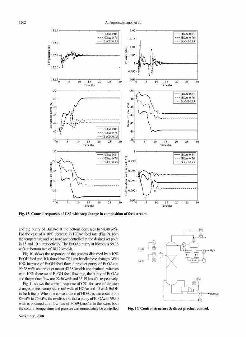
Fig. 15. Control responses of CS2 with step change in composition of feed stream.
Fig. 16. Control structure 3: direct product control.
The use of dilute acetic acid for butyl acetate production in a reactive distillation: Simulation and control studies 1263
Korean J. Chem. Eng.(Vol. 25, No. 6)
back to their set point. However, when the concentration of HOAcin the feed stream is increased from 80 wt% to 84 wt%, CS1 is notable to maintain the column pressure due to the limited capabilityof the condenser, whereas it can control the temperature at the setpoint. For a decrease in the concentration of BuOH (95 wt% BuOHin fresh feed), CS1 cannot handle this disturbance; the system be-comes unstable.
From the control responses in Figs. 9 to 11, it can be concludedthat CS1 cannot handle two unmeasured disturbances in the increaseof HOAc feed rate and the decrease of BuOH feed composition.Also, the condenser level is observed to increase in all disturbances.Since the column temperature is controlled by reboiler duty, the in-crease of reboiler heat duty results in a high vapor flow rate at thetop of the column, leading to increased pressure at the top of thecolumn. To maintain the column pressure at the desired value, higher
condenser heat duty is needed to condense more overhead vapors,resulting in high liquid level in the reflux drum. However, since theorganic reflux flow is fixed, the increase in distillate rate is the onlyway to maintain condenser liquid level. As a result, this control struc-ture cannot cope with the liquid level in the reflux drum.3. Control Structure 2 (CS2)
Fig. 12 shows a schematic diagram of CS2. In this control struc-ture, the fresh feeds of HOAc and BuOH are still flow-controlledand the column pressure is controlled by manipulating the heat re-moval of the condenser. Product stream flowrate at the bottom isemployed to control the base level. As in CS1, the product compo-sition is indirectly controlled by the control of the temperature atthe 24th stage using reboiler duty as a control variable. However, thedifference between CS1 and CS2 is in organic reflux flow and con-denser level controlled-loops; the reflux drum level is controlled by
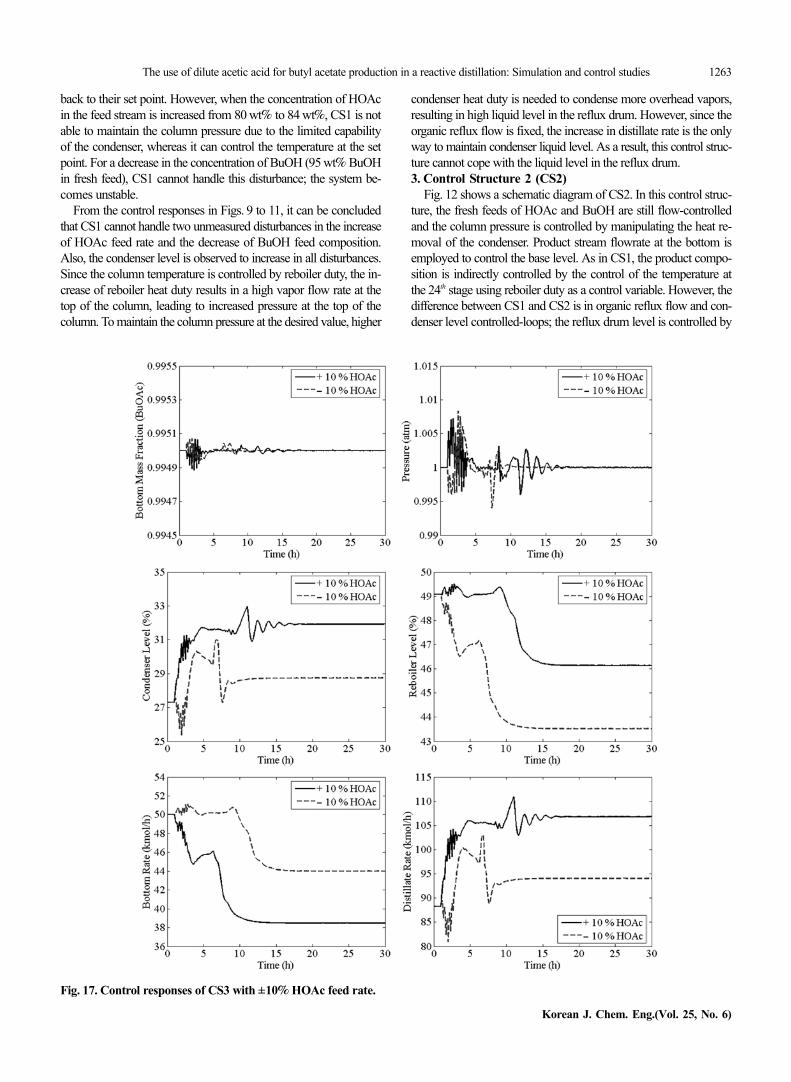
Fig. 17. Control responses of CS3 with ±10% HOAc feed rate.

1264 A. Arpornwichanop et al.
November, 2008
manipulating the reflux flow, and a constant reflux ratio (equal tothe steady state value) is maintained by adjusting the distillate flow-rate. As a result, in CS2, the reflux ratio can be controlled at a de-sired value.
The response of the column under a change of ±10% HOAc feedrate is shown in Fig. 13. From the figure, the 24th stage temperatureand pressure can be controlled at the desired set point while the liquidlevel in reflux drum is not higher than 50%. However, the BuOAcproduct purity is lower than its specification (<99.5 wt%). When astep change in BuOH feed rate (±10%) is introduced, the PID con-trollers can manage this disturbance quite well; the temperature iscontrolled at the set point with shorter settling time (12 h) (Fig. 14).However, the column pressure takes a long operating time to reachthe desired target (1 atm). Under a disturbance of +10% and −10%of BuOH feed flowrate, the BuOAC products obtained are 99.21
and 99.54 wt%, respectively.The control performance of CS2 for step changes in feed com-
position is shown in Fig. 15. The CS2 can handle these changes.The controllers are able to maintain the temperature and pressureat the desired set point and the condenser liquid level is not higherthan 51%. However, the product purity of BuOAc at the bottomstream is still lower than the desired value.
From Figs. 13 to 15, it can be seen that in CS2, since the changein the organic reflux rate is allowed, the condenser level can be main-tained within the specified value (<55%). In addition, CS2 is ableto control the temperature and pressure at desired set point in all casestudies. Considering the product specification of BuOAc, althoughCS2 can accurately control the temperature of the 24th stage, theproduct composition is changed from the design value, indicatingthe limitation of CS2. Therefore, CS3 is designed for the control of
Fig. 18. Control responses of CS3 with ±10% BuOH feed rate.

The use of dilute acetic acid for butyl acetate production in a reactive distillation: Simulation and control studies 1265
Korean J. Chem. Eng.(Vol. 25, No. 6)
reactive distillation with respect to the BuOAc purity at 99.5 wt%as a desired target.4. Control Structure 3 (CS3)
In this control scheme, all important control loops are the sameas in CS2 except the composition control loop. Instead of using anindirect composition control approach, the direct composition con-trol is selected (Fig. 16). In CS3, the composition of the bottom prod-uct is assumed to be measurable and is controlled by manipulatingthe vapor boilup. It is noted that several types of instruments areavailable for composition measurement. Among these, a gas chro-matograph is the most widely used. Although the time required forcomposition analysis is a major problem, the equipment has pres-ently been enhanced and can be used for automatic control [18].
Figs. 17 and 18 show the control response when the flow rate ofHOAc and BuOH is increased and decreased by 10%, whereas Fig.
19 demonstrates the response for the step changes in feed compo-sition. It can be seen that the CS3 is able to maintain the composi-tion and pressure at the desired set point in all simulations. How-ever, an oscillation in the process response is observed at the earlyperiod time. The dynamic response of the composition control loopsin CS3 is slower than the others because of the lag time in the bot-tom composition to the reboiler duty control loop.
CONCLUSIONS
This study concentrates on the direct use of dilute acetic acid forthe synthesis of butyl acetate from esterification with butanol in areactive distillation. The influence of important design parameterson the conversion of acetic acid is evaluated at different concentra-tion of feed acetic acid. The results show that the maximum con-
Fig. 19. Control responses of CS3 with step change in composition of feed stream.

1266 A. Arpornwichanop et al.
November, 2008
version of acetic acid and purity of butyl acetate at bottom streamcan be achieved when both acetic acid and butanol feeds are intro-duced to the column at the top stage of the reactive section. Chang-ing a number of stages in the reactive section and non-reactive sec-tion has slight effect on the performance of the reactive distillationunder the studied conditions. When acetic acid with lower concen-tration is used, a higher reboiler heat duty is required in order toobtain butyl acetate at 99.5 wt% purity. Regarding the required heatduty, the use of 80 wt% acetic acid as a reactant for the synthesisof butyl acetate in a reactive distillation column seems to be practi-cal, and the optimal design of the column consists of 7 rectifying,13 reactive, and 7 stripping stages.
Based on the optimum configuration of a reactive distillation col-umn for the production of butyl acetate from dilute acetic acid (80wt%) and the obtained steady state conditions, three alternative con-trol structures are studied for controlling the reactive distillation col-umn at desired steady state conditions under unmeasured distur-bances in feed flow rate and concentration of acetic acid and butanol.The first two control structures (CS1 and CS2) employ the indirectcontrol of bottom product composition with fixed reflux flow rateand reflux ratio, respectively. Tray temperature is used to infer prod-uct composition. The third control structure uses the direct controlof the purity of butyl acetate based on an internal composition meas-urement. The results show that the use of the composition meas-urement is required to achieve the product with desired specification.
ACKNOWLEDGEMENTS
The support from the Thailand Research Fund, Commission onHigher Education, and the Graduate School of Chulalongkorn Uni-versity is gratefully acknowledged.
NOMENCLATURE
ai : activity of component i [-]BuOAc : butyl acetate [-]BuOH : butanol [-]H2O : water [-]HOAc : acetic acid [-]kf : the forward rate constant [mol/(g s)]Keq : the reaction equilibrium constant [-]T : temperature [K]
REFERENCES
1. B. Saha, S. P. Chopade and S. M. Mahajani, Catalyst Today, 60, 147(2000).
2. Z. P. Xu, A. Afacan and K. T. Chuang, The Canadian Journal ofChemical Engineering, 77, 676 (1999).
3. V. Ragaini, C. L. Bianci, C. Pirola and G. Carvoli, Applied CatalysisB: Environmental, 64, 66 (2006).
4. W. J. Hung, I. K. Lai, Y. W. Chen, S. B. Hung, H. P. Huang, M. J.Lee and C. C. Yu, Industrial & Engineering Chemistry Research,45, 1722 (2006).
5. C. A. Cardona, V. F. Marulanda and D. Young, Chemical Engineer-ing Science, 59, 5839 (2004).
6. J. Hanika, J. Kolena and Q. Smejkal, Chemical Engineering Sci-ence, 54, 5205 (1999).
7. A. Arpornwichanop, Y. Somrang and C. Wiwittanaporn, WSEASTransactions on Computers, 6, 80 (2007).
8. M. G. Sneesby, M. O. Tade, R. Datta and T. N. Smith, Industrial &Engineering Chemistry Research, 36, 1855 (1997).
9. H. Subawalla and J. R. Fair, Industrial & Engineering ChemistryResearch, 38, 3696 (1999).
10. W. L. Luyben, Industrial & Engineering Chemistry Research, 39,2935 (2000).
11. S. Assabumrungrat, D. Wongwattanasate, V. Pavarajarn, P. Praser-thdam, A. Arpornwichanop and S. Goto, Korean J. Chem. Eng., 21,1139 (2004).
12. M. Han and D. E. Clough, Korean J. Chem. Eng., 23, 540 (2006).13. M. Al-Arfaj and W. L. Luyben, Industrial & Engineering Chemis-
try Research, 39, 3298 (2000).14. S. J. Wang, D. S. H. Wong and E. K. Lee, Industrial & Engineering
Chemistry Research, 42, 5182 (2003).15. A. Singh, A. Tiwari, S. M. Mahajani and R. D. Gudi, Industrial &
Engineering Chemistry Research, 45, 2017 (2006).16. U. Sahapatsombud, A. Arpornwichanop, S. Assabumrungrat, P. Pra-
serthdam and S. Goto, Korean J. Chem. Eng., 22, 387 (2005).17. S. Steinigeweg and J. Gmehling, Industrial & Engineering Chem-
istry Research, 41, 5483 (2002).18. B. G. Liptak, Instrument engineers’ handbook: Process measure-
ment and analysis, Fourth Edition, CRC Press, Fourth Edition(2003).
19. Y. T. Tang, H. P. Huang and I. L. Chien, Journal of Chemical Engi-neering of Japan, 38, 130 (2005).


![a · (2) [12] QUESTION 6 In an experiment to determine the relationship between pressure and temperature of a ... 6.2 Extrapolate ... is a dilute form of acetic acid](https://img.pdfslide.us/doc/110x75/5abfbbf37f8b9ae45b8b4bb6/a-2-12-question-6-in-an-experiment-to-determine-the-relationship-between-pressure.jpg)