Embed Size (px)
Citation preview
III
SIMULATION OF REACTIVE DISTILLATION
COLUMN FOR n-BUTYL ACRYLATE
PRODUCTION FROM DILUTE ACRYLIC ACID
JESSLYN TAN KIM EAN
Thesis submitted in partial fulfilment of the requirements
for the award of the degree of
Bachelor of Chemical Engineering (Chemical)
Faculty of Chemical & Natural Resources Engineering
UNIVERSITI MALAYSIA PAHANG
JANUARY 2014
©JESSLYN TAN KIM EAN (2014)
VIII
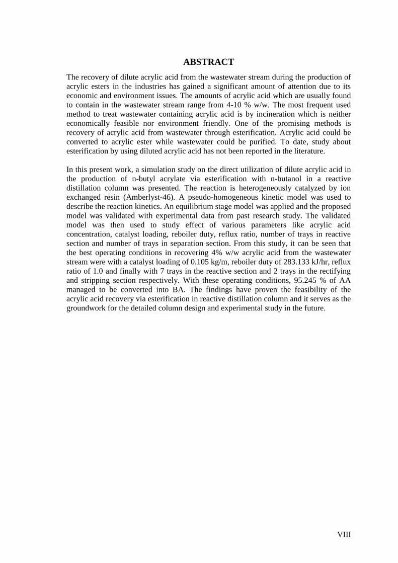
ABSTRACT
The recovery of dilute acrylic acid from the wastewater stream during the production of
acrylic esters in the industries has gained a significant amount of attention due to its
economic and environment issues. The amounts of acrylic acid which are usually found
to contain in the wastewater stream range from 4-10 % w/w. The most frequent used
method to treat wastewater containing acrylic acid is by incineration which is neither
economically feasible nor environment friendly. One of the promising methods is
recovery of acrylic acid from wastewater through esterification. Acrylic acid could be
converted to acrylic ester while wastewater could be purified. To date, study about
esterification by using diluted acrylic acid has not been reported in the literature.
In this present work, a simulation study on the direct utilization of dilute acrylic acid in
the production of n-butyl acrylate via esterification with n-butanol in a reactive
distillation column was presented. The reaction is heterogeneously catalyzed by ion
exchanged resin (Amberlyst-46). A pseudo-homogeneous kinetic model was used to
describe the reaction kinetics. An equilibrium stage model was applied and the proposed
model was validated with experimental data from past research study. The validated
model was then used to study effect of various parameters like acrylic acid
concentration, catalyst loading, reboiler duty, reflux ratio, number of trays in reactive
section and number of trays in separation section. From this study, it can be seen that
the best operating conditions in recovering 4% w/w acrylic acid from the wastewater
stream were with a catalyst loading of 0.105 kg/m, reboiler duty of 283.133 kJ/hr, reflux
ratio of 1.0 and finally with 7 trays in the reactive section and 2 trays in the rectifying
and stripping section respectively. With these operating conditions, 95.245 % of AA
managed to be converted into BA. The findings have proven the feasibility of the
acrylic acid recovery via esterification in reactive distillation column and it serves as the
groundwork for the detailed column design and experimental study in the future.
IX
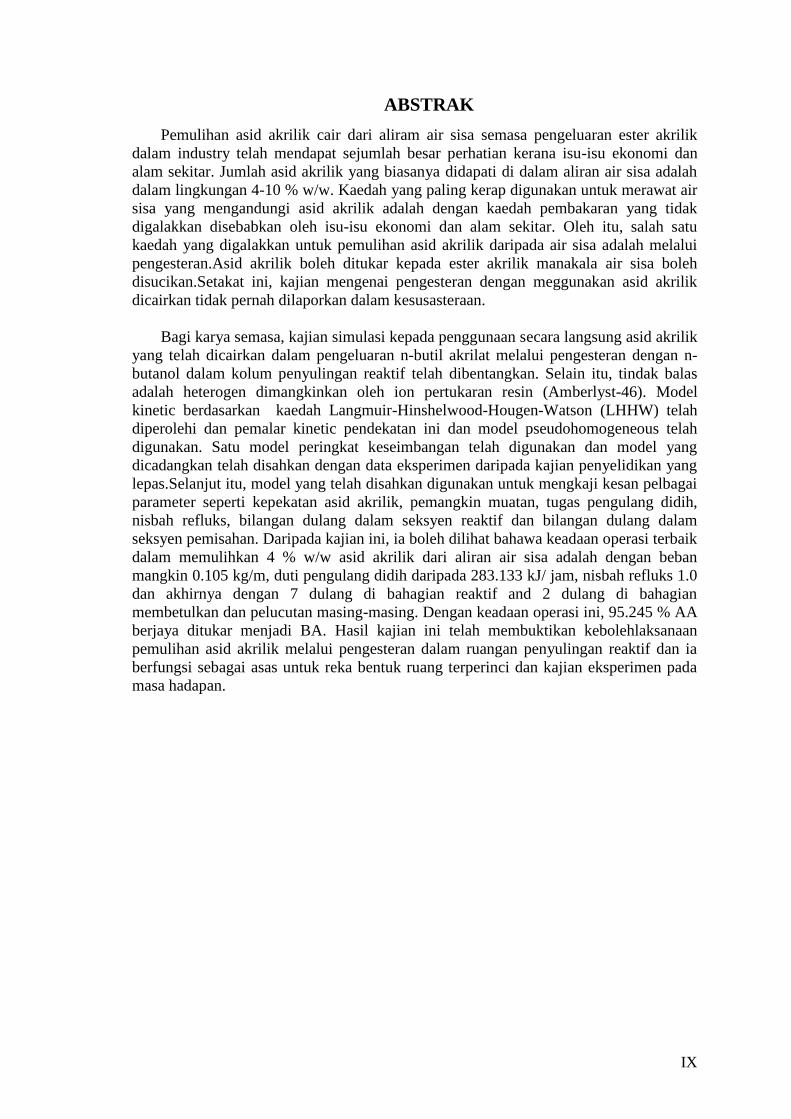
ABSTRAK
Pemulihan asid akrilik cair dari aliram air sisa semasa pengeluaran ester akrilik
dalam industry telah mendapat sejumlah besar perhatian kerana isu-isu ekonomi dan
alam sekitar. Jumlah asid akrilik yang biasanya didapati di dalam aliran air sisa adalah
dalam lingkungan 4-10 % w/w. Kaedah yang paling kerap digunakan untuk merawat air
sisa yang mengandungi asid akrilik adalah dengan kaedah pembakaran yang tidak
digalakkan disebabkan oleh isu-isu ekonomi dan alam sekitar. Oleh itu, salah satu
kaedah yang digalakkan untuk pemulihan asid akrilik daripada air sisa adalah melalui
pengesteran.Asid akrilik boleh ditukar kepada ester akrilik manakala air sisa boleh
disucikan.Setakat ini, kajian mengenai pengesteran dengan meggunakan asid akrilik
dicairkan tidak pernah dilaporkan dalam kesusasteraan.
Bagi karya semasa, kajian simulasi kepada penggunaan secara langsung asid akrilik
yang telah dicairkan dalam pengeluaran n-butil akrilat melalui pengesteran dengan n-
butanol dalam kolum penyulingan reaktif telah dibentangkan. Selain itu, tindak balas
adalah heterogen dimangkinkan oleh ion pertukaran resin (Amberlyst-46). Model
kinetic berdasarkan kaedah Langmuir-Hinshelwood-Hougen-Watson (LHHW) telah
diperolehi dan pemalar kinetic pendekatan ini dan model pseudohomogeneous telah
digunakan. Satu model peringkat keseimbangan telah digunakan dan model yang
dicadangkan telah disahkan dengan data eksperimen daripada kajian penyelidikan yang
lepas.Selanjut itu, model yang telah disahkan digunakan untuk mengkaji kesan pelbagai
parameter seperti kepekatan asid akrilik, pemangkin muatan, tugas pengulang didih,
nisbah refluks, bilangan dulang dalam seksyen reaktif dan bilangan dulang dalam
seksyen pemisahan. Daripada kajian ini, ia boleh dilihat bahawa keadaan operasi terbaik
dalam memulihkan 4 % w/w asid akrilik dari aliran air sisa adalah dengan beban
mangkin 0.105 kg/m, duti pengulang didih daripada 283.133 kJ/ jam, nisbah refluks 1.0
dan akhirnya dengan 7 dulang di bahagian reaktif and 2 dulang di bahagian
membetulkan dan pelucutan masing-masing. Dengan keadaan operasi ini, 95.245 % AA
berjaya ditukar menjadi BA. Hasil kajian ini telah membuktikan kebolehlaksanaan
pemulihan asid akrilik melalui pengesteran dalam ruangan penyulingan reaktif dan ia
berfungsi sebagai asas untuk reka bentuk ruang terperinci dan kajian eksperimen pada
masa hadapan.
X
TABLE OF CONTENTS
SUPERVISOR’S DECLARATION ....................................................................... IV STUDENT’S DECLARATION ............................................................................. V Dedication .......................................................................................................... VI ACKNOWLEDGEMENT ................................................................................... VII ABSTRACT ..................................................................................................... VIII ABSTRAK ......................................................................................................... IX TABLE OF CONTENTS ...................................................................................... X
LIST OF FIGURES ............................................................................................ XII LIST OF TABLES ............................................................................................. XIV LIST OF SYMBOL ........................................................................................... XVI LIST OF ABBREVIATION .............................................................................. XVII 1 INTRODUCTION ......................................................................................... 1
1.1 Background of study and motivation ..................................................... 1 1.2 Statement of problem ............................................................................ 3
1.3 Objectives ............................................................................................. 4 1.4 Scope of study ...................................................................................... 4 1.5 Organisation of thesis ........................................................................... 4
2 LITERATURE REVIEW ............................................................................... 6
2.1 Overview ............................................................................................... 6
2.2 Introduction ........................................................................................... 6 2.3 Wastewater treatment technology for carboxylic acid recovery ............ 6 2.4 General esterification system ................................................................ 8
2.5 Esterification reaction to recover carboxylic acid from wastewater ..... 10 2.6 Catalyst in esterification ...................................................................... 11
2.6.1 Introduction .................................................................................... 11
2.6.2 Homogeneous ................................................................................. 12
2.6.3 Heterogeneous ................................................................................ 12
2.7 Reactive distillation technology ........................................................... 13
2.7.1 Introduction .................................................................................... 13
2.7.2 Advantages of RDC ........................................................................ 17
2.8 Reactive distillation with structured packings ...................................... 17 2.9 RDC modelling and simulation ............................................................ 19
2.10 Summary ......................................................................................... 21
3 METHODOLOGY ...................................................................................... 22
3.1 Overview ............................................................................................. 22 3.2 Introduction ......................................................................................... 22 3.3 Process design description ................................................................. 22
3.4 RDC modelling .................................................................................... 23 3.5 Equilibrium stage model ...................................................................... 24
3.5.1 Equilibrium stage model equation ..................................................... 24
3.6 Thermodynamic aspect ....................................................................... 26 3.7 Reaction kinetics ................................................................................. 28 3.8 RADFRAC module .............................................................................. 30 3.9 Summary ............................................................................................. 41
4 RESULTS AND DISCUSSION .................................................................... 42
XI
4.1 Overview ............................................................................................. 42 4.2 Model validation .................................................................................. 42 4.3 Process analysis ................................................................................. 45
4.3.1 Acrylic acid (AA) concentration ....................................................... 45
4.3.2 Catalyst loading .............................................................................. 47
4.3.3 Reboiler duty .................................................................................. 48 4.3.4 Reflux ratio .................................................................................... 50
4.3.5 Number of trays required in reactive section ...................................... 53
4.3.6 Number of trays required in separation section ................................... 55
4.4 The optimized process ........................................................................ 58
4.5 Summary ............................................................................................. 59
5 CONCLUSION AND RECOMMENDATION ............................................... 60
5.1 Overview ............................................................................................. 60 5.2 Introduction ......................................................................................... 60
5.3 Conclusion for overall findings ............................................................ 60 5.4 Recommendation ................................................................................ 61
REFERENCES ................................................................................................... 62 APPENDIX A .................................................................................................... 68
APPENDIX B .................................................................................................... 73 APPENDIX C .................................................................................................... 78 APPENDIX D .................................................................................................... 82
APPENDIX E .................................................................................................... 87
APPENDIX F .................................................................................................... 93
APPENDIX G .................................................................................................... 97
APPENDIX H .................................................................................................. 101
XII
LIST OF FIGURES
Figure 2.1: a) A conventional process consisting of a reactor followed by three
distillation column for a reaction sequence A + B C + D. b) The reactive distillation
configuration where the reactive sections in a) and b) are indicated by grid lines
(Stichlmair and Frey, 1999). ................................................................................ 14
Figure 3.1: Pilot scale RDC for the production of n-Butyl Acrylate (Zeng et al., 2006).
......................................................................................................................... 23
Figure 3.2: Equilibrium stage model. Adapted from Taylor and Krishna (2003) (Blue:
Liquid, Green: Vapor). ........................................................................................ 25
Figure 3.3: Selection of appropriate thermodynamic models base on the type of
compounds involves (Carlson, 1996). ................................................................... 27
Figure 3.4: Arrhenius diagram of the rate constant for forward reaction .................... 30
Figure 3.5: Arrhenius diagram of the rate constant for backward reaction ................. 30
Figure 3.6: Basic RADFRAC simulation steps to be taken for the simulation of the
reactive distillation process. ................................................................................. 31
Figure 3.7: Defining the flowsheet for reactive distillation process. .......................... 32
Figure 3.8: Entering of the component present to the component selection sheet. ....... 33
Figure 3.9: Input of thermodynamic model into the properties specification sheet. ..... 33
Figure 3.10: Input of Acrylic Acid feed stream data into Stream 1 specification sheet. 34
Figure 3.11: Input of n-Butanol feed stream data into Stream 2 specification sheet. ... 34
Figure 3.12: Input of operating specification to Block R-101 configuration sheet. ...... 35
Figure 3.13: Feed stages of AA and n-Butanol entered into Block R-101 configuration
sheet. ................................................................................................................. 36
Figure 3.14: Block R-101 pressure sheet for input of condenser pressure. ................. 36
Figure 3.15: Specification for pack sizing in the rectifying section. .......................... 37
Figure 3.16: Specification for pack sizing in the reaction section. ............................ 37
Figure 3.17: Specification for pack sizing in stripping section. ................................ 38
Figure 3.18: Input of stoichiometry of reaction into Block R-101 stoichiometry sheet. 38
Figure 3.19: Input of kinetic specification to the Block R-101 kinetic sheet for forward
reaction. ............................................................................................................. 39
Figure 3.20: Input of kinetic specification to the Block R-101 kinetic sheet for backward
reaction ............................................................................................................. 39
Figure 3.21: Simulation results of liquid composition. ............................................ 40
Figure 3.22: Simulation results of temperature, pressure, heat duty, liquid flow and
vapor flow.......................................................................................................... 40
Figure 3.23: Temperature profile plotted in RADFRAC .......................................... 41
Figure 4.1: Temperature profile of n-butyl acrylate production. ............................... 44
XIII
Figure 4.2: The effects on conversion and reboiler duty for different AA concentration
......................................................................................................................... 46
Figure 4.3: Conversion as a function of catalyst loading .......................................... 48
Figure 4.4: Conversion as a function of reboiler duty .............................................. 49
Figure 4.5: Average temperature in the reactive section and conversion as a function of
reboiler duty ....................................................................................................... 50
Figure 4.6: Conversion as a function of reflux ratio ................................................ 51
Figure 4.7: Liquid composition of AA, BuOH and BA as a function of reflux ratio.... 53
Figure 4.8: Temperature profile of reactive section as a function of reflux ratio ......... 53
Figure 4.9: Conversion as a function of number of trays in reactive section ............... 54
Figure 4.10: Conversion as a function of number of rectifying stages ....................... 56
Figure 4.11: Conversion as a function of number of stripping stages ........................ 56
Figure 4.12: Liquid composition of AA and BA as a function of rectifying stages ..... 57
Figure 4.13: Liquid composition of AA and BA as a function of stripping stages....... 57
Figure 4.14: Mass balance for the esterification of dilute AA .................................. 58
Figure A.1: Data analysis in Polymath for 350K .................................................... 68
Figure A.2: Data analysis in Polymath for 360K .................................................... 69
Figure A.3: Data analysis in Polymath for 370K .................................................... 70
Figure A.4: Data analysis in Polymath for 375K .................................................... 71
Figure A.5: Data analysis in Polymath for 380K .................................................... 72
XIV
LIST OF TABLES
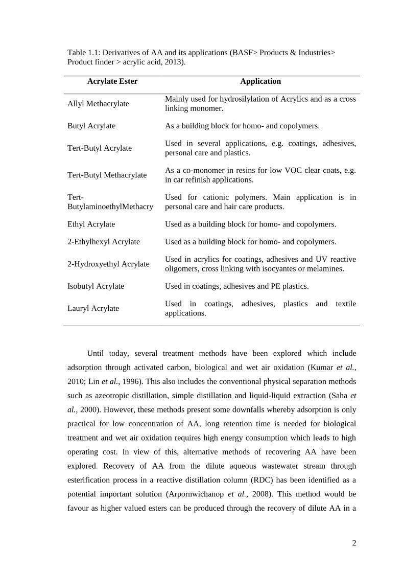
Table 1.1: Derivatives of AA and its applications (BASF> Products & Industries>
Product finder > acrylic acid, 2013). ....................................................................... 2
Table 2.1: Methods which have been applied for the recovery of carboxylic acids. ...... 7
Table 2.2: Summary of esterification process that have been studied by past researchers.
........................................................................................................................... 9
Table 2.3: Summary of esterification reaction which have been applied in recovery of
carboxylic acid through RDC. .............................................................................. 10
Table 2.4: Important industrial process investigated in RDC ................................... 15
Table 2.5: Summary of different types of structured packings available. (Sulzer
Chemtech, n.d). .................................................................................................. 18
Table 2.6: Summary of RD, thermodynamic and kinetic models. ............................. 20
Table 3.1: Kinetics Parameters for the Pseudohomogeneous Kinetic Model .............. 29
Table 3.2: HETP values of the packing used in reactive distillation (Niesbach et al.,
2012). ................................................................................................................ 31
Table 4.1: Specification of Pilot scale RDC. Adopted from Niesbach et al. (2012)..... 42
Table 4.2: Operating condition of experiment E7 ................................................... 43
Table 4.3: Comparison of simulation and experimental results for temperature profile.
......................................................................................................................... 44
Table 4.4: Operating conditions for catalyst loading sensitivity analysis ................... 47
Table 4.5: Operating conditions for reboiler duty sensitivity analysis ....................... 49
Table 4.6: Operating condition for reflux ratio sensitivity analysis ........................... 51
Table 4.7: Boiling point of each component ........................................................... 52
Table 4.8: Operating conditions for the number of trays in reactive section sensitivity
analysis ............................................................................................................. 54
Table 4.9: Operating conditions for number of trays of rectifying and stripping section
sensitivity analysis .............................................................................................. 55
Table 4.10: Optimized condition for esterification of dilute AA ............................... 59
Table B.1: Result summary for AA concentration at 4 % w/w ................................. 73
Table B.2: Result summary of AA concentration at 5 % w/w .................................. 74
Table B.3: Result summary of AA concentration at 10 % w/w ................................. 75
Table B.4: Result summary of AA concentration at 15 % w/w ................................. 76
Table B.5: Result summary of AA concentration at 20 % w/w ................................. 77
Table C.1: Result summary of catalyst loading at 0.055 kg/m .................................. 78
Table C.2: Result summary of catalyst loading at 0.105 kg/m .................................. 79
Table C.3: Result summary of catalyst loading at 0.155 kg/m .................................. 80
Table C.4: Result summary of catalyst loading at 0.205 kg/m .................................. 81
XV
Table D.1: Result summary of reboiler duty at 265 kJ/hr ......................................... 82
Table D.2: Result summary of reboiler duty at 270 kJ/hr ......................................... 83
Table D.3: Result summary of reboiler duty at 275 kJ/hr ......................................... 84
Table D.4: Result summary of reboiler duty at 280 kJ/hr ......................................... 85
Table D.5: Result summary of reboiler duty at 283.133 kJ/hr .................................. 86
Table E.1: Result summary of reflux ratio at 1.0 .................................................... 87
Table E.2: Result summary of reflux ratio at 1.2 .................................................... 88
Table E.3: Result summary of reflux ratio at 1.4 .................................................... 89
Table E.4: Result summary of reflux ratio at 1.6 .................................................... 90
Table E.5: Result summary of reflux ratio at 1.8 .................................................... 91
Table E.6: Result summary of reflux ratio at 2.0 .................................................... 92
Table F.1: Result summary of 1 reactive tray ......................................................... 93
Table F.2: Result summary of 3 reactive trays........................................................ 94
Table F.3: Result summary of 5 reactive trays........................................................ 95
Table F.4: Result summary of 7 reactive trays........................................................ 96
Table G.1: Result summary of 0 stripping trays...................................................... 97
Table G.2: Result summary of 2 stripping trays...................................................... 98
Table G.3: Result summary of 3 stripping trays...................................................... 99
Table G.4: Result summary of 4 stripping trays.................................................... 100
Table H.1: Result summary of 0 rectifying trays .................................................. 101
Table H.2: Result summary of 2 rectifying trays .................................................. 102
Table H.3: Result summary of 4 rectifying trays .................................................. 103
Table H.4: Result summary of 6 rectifying trays .................................................. 104
Table H.5: Result summary of 8 rectifying trays .................................................. 105
Table H.6: Result summary of 12 rectifying trays ................................................. 106

XVI
LIST OF SYMBOL SYMBOL DEFINITION
ai activity of component i (mol/mol)
Cact concentration of active sites (mol/kg3)
Ci concentration of component i (kmol/L)
Ea activation energy (J/mol)
ᵞ activity coefficient
Ka activity-based kinetic constant
k rate constant for pseudo homogeneous model
ko pre-exponential factor in Arrhenius equation
Keq equilibrium constant
mcat,dry mass of dry catalyst per meter packing height (kg/m)
ṅi mole flow rate of flow i (kg/hr)
R ideal gas constant (J/ (mol K))
ri reaction rate of component i (mol/s)
T temperature (K)
vi stoichiometric coefficient
XVII
LIST OF ABBREVIATION AA acrylic acid
BuOH n-butanol
BA n-butyl acrylate
CSTR continuous stirred-tank reactor
EQ equilibrium model
ER Eley-Rideal
HETP height equivalent of a theoretical plate
H2O water
LH Langmuir-Hinshelwood
LHHW Langmuir-Hinshelwood-Hougen-Watson
LLE liquid-liquid equilibrium
MTBE methyl tertiary butyl ether
NEQ non-equilibrium model
NRTL non-random two-liquid model
PH pseudo homogeneous model
RD reactive distillation
RDC reactive distillation column
RR reflux ratio
SAT super absorbent polymer
UNIFAC UNIQUAC Functional-group Activity Coefficient model
UNIQUAC UNIversal QUAsiChemical model
VLE vapour-liquid equilibrium
WAO wet air oxidation
1
1 INTRODUCTION
1.1 Background of study and motivation
Acrylic acid (AA) and its derivatives as the basic building block in the chemical
synthesis process have received overwhelming demands for the last few years (Bell,
2003). This in turn has caused the overall production of AA to rise from 3.4 million tons
per year to 4.7 million tons per year from year 2003 until 2006 (Glauser et al., 2007). It
was reported that the global capacity demand of AA for second quarter of 2011 reached
5.32 million ton per year to cater the demand from United States, Europe, Japan and
China. AA is mainly used for producing super absorbent polymer (SAT) which mainly
used in baby diapers, adult protective underwear and sanitary napkins
(ResearchInChina, 2012; IHS Inc., 2011).
One of the important derivatives of AA is n-Butyl Acrylate (BA), which values
at about 30% of the global demand of AA according to Nexant Inc. (2006). It is widely
used in the industry as a precursor for varnishes, adhesives and finishes of textiles and
papers (Zeng et al., 2006; Altiokka and Ödeş, 2009). Other derivatives of AA and its
applications are shown in Table 1.1.
AA possesses harmful properties which could lead to health complication in
living species. According to the Dow Chemical Company (2010), AA is corrosive and
toxic if absorbed through the skin or inhaled. It is a strong irritant to the skins, eyes and
mucous membranes in humans. Possible blindness may occur if its liquids were
splashed into eyes. In a typical AA production plant, the wastewater contains 4-10%
w/w of AA (Kumar et al., 2010). Some other toxicant of AA family besides AA such as
acrylonitrile and acetonitrile are also present in the wastewater stream which is mostly
being incinerated due to its high chemical oxygen demand and total organic content.
This method suffers from several drawbacks because it is neither economic feasible nor
environmental friendly.
2
Table 1.1: Derivatives of AA and its applications (BASF> Products & Industries>
Product finder > acrylic acid, 2013).
Acrylate Ester Application
Allyl Methacrylate Mainly used for hydrosilylation of Acrylics and as a cross
linking monomer.
Butyl Acrylate As a building block for homo- and copolymers.
Tert-Butyl Acrylate Used in several applications, e.g. coatings, adhesives,
personal care and plastics.
Tert-Butyl Methacrylate As a co-monomer in resins for low VOC clear coats, e.g.
in car refinish applications.
Tert-
ButylaminoethylMethacry
Used for cationic polymers. Main application is in
personal care and hair care products.
Ethyl Acrylate Used as a building block for homo- and copolymers.
2-Ethylhexyl Acrylate Used as a building block for homo- and copolymers.
2-Hydroxyethyl Acrylate Used in acrylics for coatings, adhesives and UV reactive
oligomers, cross linking with isocyantes or melamines.
Isobutyl Acrylate Used in coatings, adhesives and PE plastics.
Lauryl Acrylate Used in coatings, adhesives, plastics and textile
applications.
Until today, several treatment methods have been explored which include
adsorption through activated carbon, biological and wet air oxidation (Kumar et al.,
2010; Lin et al., 1996). This also includes the conventional physical separation methods
such as azeotropic distillation, simple distillation and liquid-liquid extraction (Saha et
al., 2000). However, these methods present some downfalls whereby adsorption is only
practical for low concentration of AA, long retention time is needed for biological
treatment and wet air oxidation requires high energy consumption which leads to high
operating cost. In view of this, alternative methods of recovering AA have been
explored. Recovery of AA from the dilute aqueous wastewater stream through
esterification process in a reactive distillation column (RDC) has been identified as a
potential important solution (Arpornwichanop et al., 2008). This method would be
favour as higher valued esters can be produced through the recovery of dilute AA in a
3
RDC which in turn would overcome the economic and environmental issue (Taylor and
Krishna, 2000).
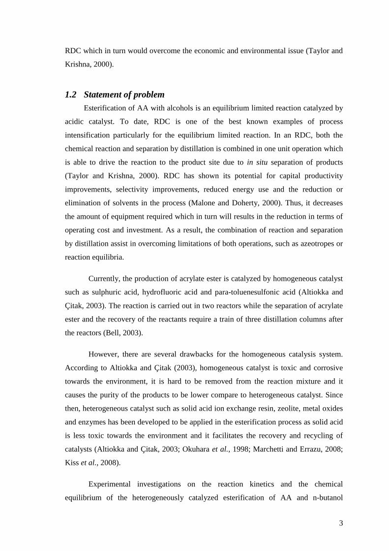
1.2 Statement of problem
Esterification of AA with alcohols is an equilibrium limited reaction catalyzed by
acidic catalyst. To date, RDC is one of the best known examples of process
intensification particularly for the equilibrium limited reaction. In an RDC, both the
chemical reaction and separation by distillation is combined in one unit operation which
is able to drive the reaction to the product site due to in situ separation of products
(Taylor and Krishna, 2000). RDC has shown its potential for capital productivity
improvements, selectivity improvements, reduced energy use and the reduction or
elimination of solvents in the process (Malone and Doherty, 2000). Thus, it decreases
the amount of equipment required which in turn will results in the reduction in terms of
operating cost and investment. As a result, the combination of reaction and separation
by distillation assist in overcoming limitations of both operations, such as azeotropes or
reaction equilibria.
Currently, the production of acrylate ester is catalyzed by homogeneous catalyst
such as sulphuric acid, hydrofluoric acid and para-toluenesulfonic acid (Altiokka and
Çitak, 2003). The reaction is carried out in two reactors while the separation of acrylate
ester and the recovery of the reactants require a train of three distillation columns after
the reactors (Bell, 2003).
However, there are several drawbacks for the homogeneous catalysis system.
According to Altiokka and Çitak (2003), homogeneous catalyst is toxic and corrosive
towards the environment, it is hard to be removed from the reaction mixture and it
causes the purity of the products to be lower compare to heterogeneous catalyst. Since
then, heterogeneous catalyst such as solid acid ion exchange resin, zeolite, metal oxides
and enzymes has been developed to be applied in the esterification process as solid acid
is less toxic towards the environment and it facilitates the recovery and recycling of
catalysts (Altiokka and Çitak, 2003; Okuhara et al., 1998; Marchetti and Errazu, 2008;
Kiss et al., 2008).
Experimental investigations on the reaction kinetics and the chemical
equilibrium of the heterogeneously catalyzed esterification of AA and n-butanol
4
(BuOH) were investigated in the previous work (Schwarzer and Hoffmann, 2002). To
the best of our knowledge, RDC is not practiced for the recovery of AA from diluted
aqueous wastewater and only a few publications on the production of BA in a RDC can
be found in the literature (Niesbach et al., 2012; Niesbach et al., 2013).
In the present study, AA will be recovered by esterification of wastewater
containing AA with BuOH catalyzed by heterogeneous catalyst, ion-exchange resin in a
RDC. Since the presence of water in the reactant could reduce the equilibrium
conversion due to the shift of reaction equilibrium to the reactant side, efficiency of the
AA recovery will be examined in a reactive distillation column (RDC) through
simulation study.
1.3 Objectives
This study aims to examine the efficiency of recovering AA from the wastewater
containing AA. The effects of important operating parameters for the esterification of
diluted AA with Butanol (BuOH) in RDC are investigated.
1.4 Scope of study
In this research, the suitable RDC models (equilibrium or non-equilibrium
model), thermodynamics models (UNIFAC, UNIQUAC or NRTL) and reaction kinetics
(Langmuir-Hinshelwood-Hougen-Watson, Eley-Rideal or pseudo-homogeneous) were
screened before it is employed for the simulation studies. The verification for the
simulation on the RDC was carried out by comparing with pilot scale data from past
research. Several operating parameters such as acrylic acid concentration, catalyst
loading, reflux ratio, reboiler duty and column configuration were varied during the
simulation using the validated model.
1.5 Organisation of thesis
This thesis consists of 5 chapters. Chapter 1 (Introduction) provides a description
on the application of acrylic acid (AA) and its derivatives in the chemical industries and
the effect of its harmful properties. The conventional methods of recovering AA from
the dilute aqueous wastewater are briefly described. This chapter includes the problem
statements which lead to the identification of the objectives and scopes for the present
study. Finally, the organization of thesis is presented.
5
Chapter 2 (Literature review) describes in details the conventional methods
which have been applied in the recovery of AA from wastewater. Besides that, different
types of esterification process and catalysts that have been investigated by past
researches are also review in this chapter. Information concerning with the
implementation of reactive distillation technology for the production of different types
of carboxylic acid esters which were review from past researches have also lead to the
consideration of catalysts, thermodynamics, modelling and simulation for the reactive
distillation(RD) implementation for the current study.
The modelling and simulation procedure is illustrated in detail in Chapter 3
(Methodology). It gives a review on the procedures involved during the simulation of
RDC using ASPEN PLUS V7.0 software. The selection of the suitable RD model,
thermodynamics model and kinetics model are also being described in this chapter.
Chapter 4 (Results and discussion) is devoted to the simulation results obtained
and discussion of the present study. Validation of the RD model for this present study is
carried out by comparing with experimental results from past research papers which can
be found in the literature. Besides that, the suitable ranges of operating parameters for
the recovery of AA in RDC are also being determined after the model has been
validated.
Chapter 5 (Conclusion and recommendation) focuses on the conclusion that can
be made by the end of the study after analysis the simulation results. The best operating
conditions for the recovery of dilute AA in RDC are also presented in this chapter.
Lastly, several recommendations are presented in this chapter in order to be considered
in future studies.
6
2 LITERATURE REVIEW
2.1 Overview
This chapter reviewed on the available technology in recovering carboxylic acid
from diluted aqueous wastewater streams in today’s world. It also describes the
recovery of carboxylic acid through esterification process which has been carried out in
RDC by past researchers. Besides that, the different types of process which have been
investigated through RDC and hardware selections in modelling RDC are also being
reviewed in the later parts of this chapter. Finally, a review on the types of RD,
thermodynamic and kinetic models which have been investigated in the past for the
modelling and simulation of RDC is presented in the final part of this chapter.
2.2 Introduction
Acrylic Acid (AA) is very toxic to living species and it appears as an unsaturated
organic acid. During the manufacture of acrylic esters, acrylic acid is being released to
the environment. It have been reported that in a typical AA plant, the concentration of
AA range from 10-20 g/l in the wastewater stream (Kumar et al., 2008). Thus, the
recovery of dilute acrylic acid from the wastewater stream has become very important
due to its economical and environmental awareness.
2.3 Wastewater treatment technology for carboxylic acid recovery
According to Cheremisinoff (2002, p.1), wastewater treatment technology can be
divided into three areas: Physical Methods, Chemical Methods and Energy Intensive
Methods. Physical methods for wastewater treatment are mainly represented by solid-
liquid separation techniques. Filtration plays an important role in solid-liquid separation
techniques as it is an integral component of wastewater treatment application. In
understanding the role of filtration, it is important to make distinctions not only with
other technologies applied in the purification of industrial water, but also includes the
objectives of different unit processes.
Besides that, chemical methods for wastewater treatment depend upon the
chemical reaction of the contaminants to be recovered from the water. It is applied as a
7
stand-alone technologies as well as an integral part of the treatment process with
physical methods.
Moreover, as for energy intensive technologies, the thermal methods have
gained much attention due to its dual role in wastewater treatment applications. They
can be utilized as a mean of sterilization or utilized to the processing of solid wastes or
sludge. In the latter cases, thermal methods can also be applied to sterilize sludge
contaminated with organic contaminants.
Several methods have been explored in recovering carboxylic acids from
wastewater. In the past, the conventional method includes adsorption through activated
carbon (Kumar et al., 2010) and distillation and extraction (Arpornwichanop et al.,
2008). However, distillation approach requires high energy usage in vaporizing the
water present whereas, extraction is limited by the phase separation and distribution of
the component (Saha et al., 2000). As for adsorption through activated carbon, it only
deals with chemical wastewater with a low concentration of organic compounds (Kumar
et al., 2010). Wet air oxidation (WAO) treatment has also been explored as an
alternative method. Due to the high energy consumption which leads to high operation
cost, this method is not being favoured (Lin et al., 1996).
Thus, reactive distillation has been introduced as a method in recovering acrylic
acid from its dilute aqueous solution. It applies the concept of using the recovered
acrylic acid as the reactant for esterification. According to Arpornwichanop et al.
(2008), this approach is able to produce a higher valued ester, which could save raw
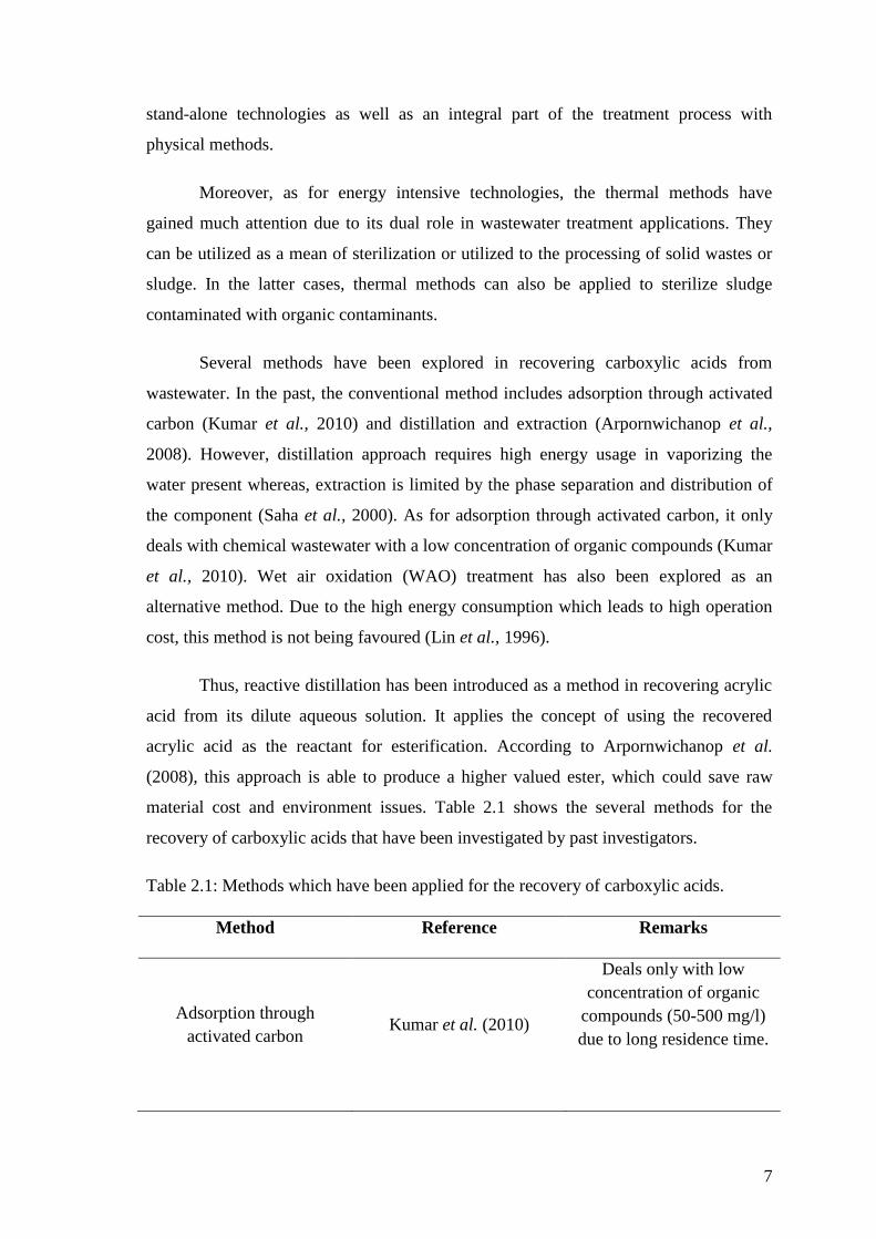
material cost and environment issues. Table 2.1 shows the several methods for the
recovery of carboxylic acids that have been investigated by past investigators.
Table 2.1: Methods which have been applied for the recovery of carboxylic acids.
Method Reference Remarks
Adsorption through
activated carbon Kumar et al. (2010)
Deals only with low
concentration of organic
compounds (50-500 mg/l)
due to long residence time.
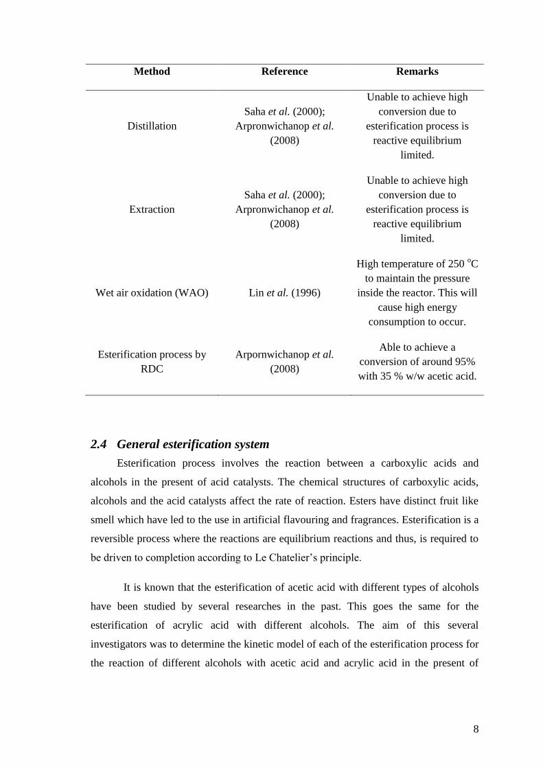
8
Method Reference Remarks
Distillation
Saha et al. (2000);
Arpronwichanop et al.
(2008)
Unable to achieve high
conversion due to
esterification process is
reactive equilibrium
limited.
Extraction
Saha et al. (2000);
Arpronwichanop et al.
(2008)
Unable to achieve high
conversion due to
esterification process is
reactive equilibrium
limited.
Wet air oxidation (WAO) Lin et al. (1996)
High temperature of 250 oC
to maintain the pressure
inside the reactor. This will
cause high energy
consumption to occur.
Esterification process by
RDC
Arpornwichanop et al.
(2008)
Able to achieve a
conversion of around 95%
with 35 % w/w acetic acid.
2.4 General esterification system
Esterification process involves the reaction between a carboxylic acids and
alcohols in the present of acid catalysts. The chemical structures of carboxylic acids,
alcohols and the acid catalysts affect the rate of reaction. Esters have distinct fruit like
smell which have led to the use in artificial flavouring and fragrances. Esterification is a
reversible process where the reactions are equilibrium reactions and thus, is required to
be driven to completion according to Le Chatelier’s principle.
It is known that the esterification of acetic acid with different types of alcohols
have been studied by several researches in the past. This goes the same for the
esterification of acrylic acid with different alcohols. The aim of this several
investigators was to determine the kinetic model of each of the esterification process for
the reaction of different alcohols with acetic acid and acrylic acid in the present of
9
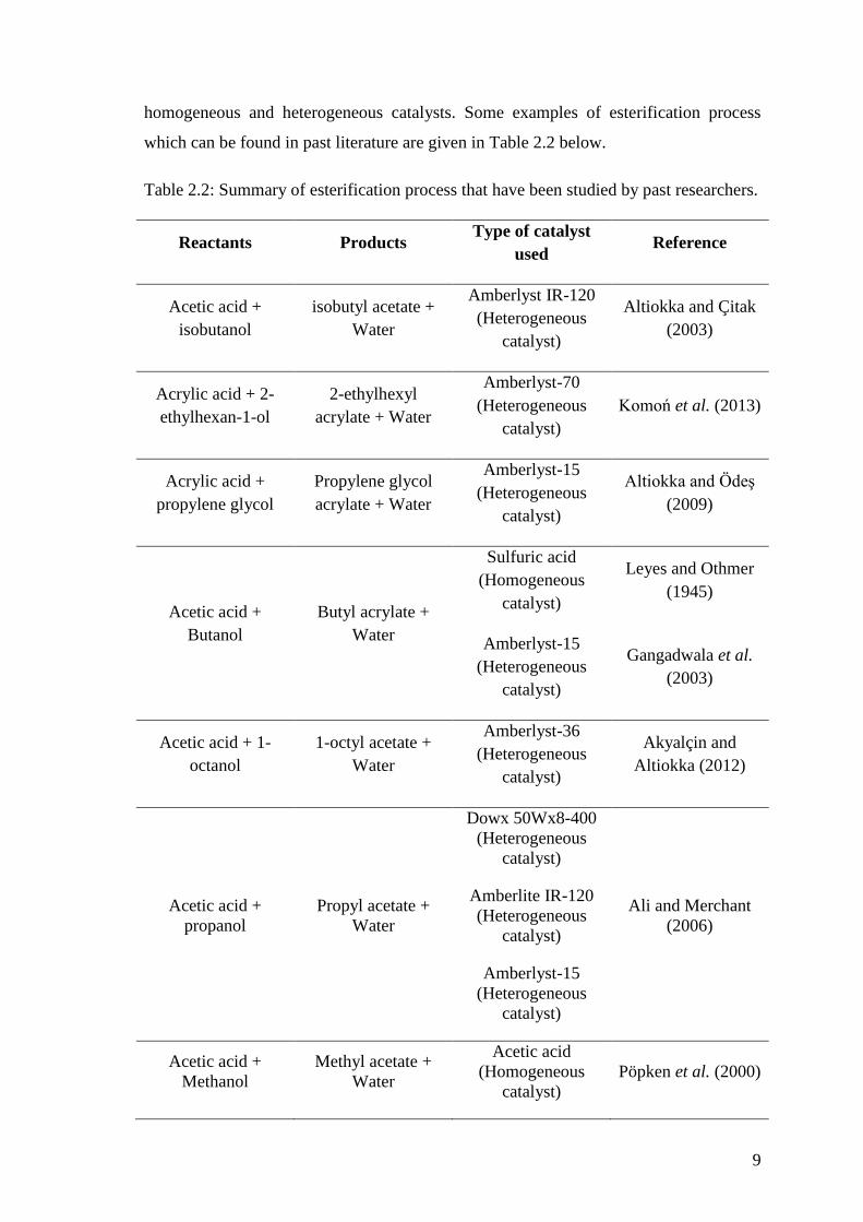
homogeneous and heterogeneous catalysts. Some examples of esterification process
which can be found in past literature are given in Table 2.2 below.
Table 2.2: Summary of esterification process that have been studied by past researchers.
Reactants Products Type of catalyst
used Reference
Acetic acid +
isobutanol
isobutyl acetate +
Water
Amberlyst IR-120
(Heterogeneous
catalyst)
Altiokka and Çitak
(2003)
Acrylic acid + 2-
ethylhexan-1-ol
2-ethylhexyl
acrylate + Water
Amberlyst-70
(Heterogeneous
catalyst)
Komoń et al. (2013)
Acrylic acid +
propylene glycol
Propylene glycol
acrylate + Water
Amberlyst-15
(Heterogeneous
catalyst)
Altiokka and Ödeş
(2009)
Acetic acid +
Butanol
Butyl acrylate +
Water
Sulfuric acid
(Homogeneous
catalyst)
Leyes and Othmer
(1945)
Amberlyst-15
(Heterogeneous
catalyst)
Gangadwala et al.
(2003)
Acetic acid + 1-
octanol
1-octyl acetate +
Water
Amberlyst-36
(Heterogeneous
catalyst)
Akyalçin and
Altiokka (2012)
Acetic acid +
propanol
Propyl acetate +
Water
Dowx 50Wx8-400
(Heterogeneous
catalyst)
Ali and Merchant
(2006)
Amberlite IR-120
(Heterogeneous
catalyst)
Amberlyst-15
(Heterogeneous
catalyst)
Acetic acid +
Methanol
Methyl acetate +
Water
Acetic acid
(Homogeneous
catalyst)
Pöpken et al. (2000)
10
Reactants Products Type of catalyst
used Reference
Acetic acid +
Methanol
Methyl acetate +
Water
Amberlyst-15
(Heterogeneous
catalyst)
Pöpken et al. (2000)
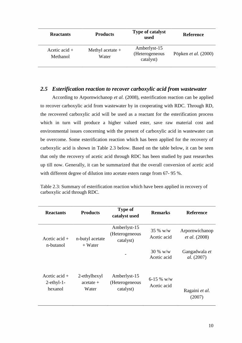
2.5 Esterification reaction to recover carboxylic acid from wastewater
According to Arpornwichanop et al. (2008), esterification reaction can be applied
to recover carboxylic acid from wastewater by in cooperating with RDC. Through RD,
the recovered carboxylic acid will be used as a reactant for the esterification process
which in turn will produce a higher valued ester, save raw material cost and
environmental issues concerning with the present of carboxylic acid in wastewater can
be overcome. Some esterification reaction which has been applied for the recovery of
carboxylic acid is shown in Table 2.3 below. Based on the table below, it can be seen
that only the recovery of acetic acid through RDC has been studied by past researches
up till now. Generally, it can be summarized that the overall conversion of acetic acid
with different degree of dilution into acetate esters range from 67- 95 %.
Table 2.3: Summary of esterification reaction which have been applied in recovery of
carboxylic acid through RDC.
Reactants Products Type of
catalyst used Remarks Reference
Acetic acid +
n-butanol
n-butyl acetate
+ Water
Amberlyst-15
(Heterogeneous
catalyst)
35 % w/w
Acetic acid
Arpornwichanop
et al. (2008)
- 30 % w/w
Acetic acid
Gangadwala et
al. (2007)
Acetic acid +
2-ethyl-1-
hexanol
2-ethylhexyl
acetate +
Water
Amberlyst-15
(Heterogeneous
catalyst)
6-15 % w/w
Acetic acid
Ragaini et al.
(2007)
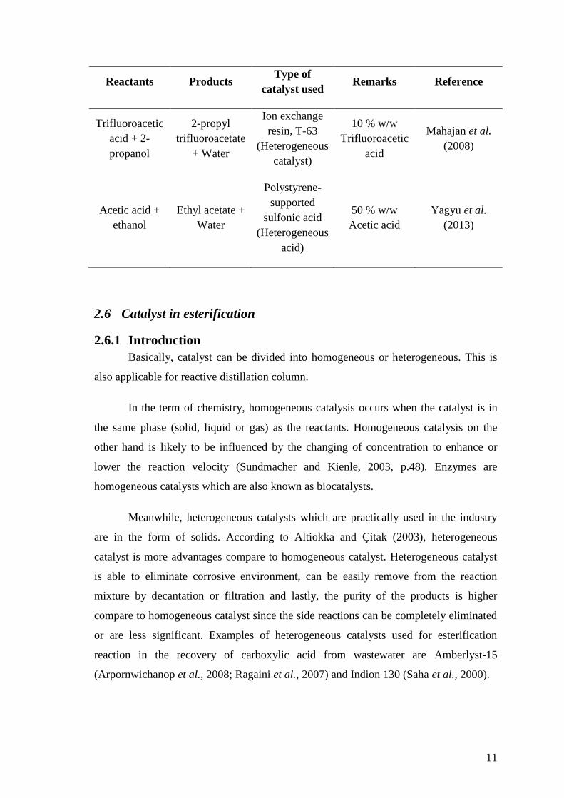
11
Reactants Products Type of
catalyst used Remarks Reference
Trifluoroacetic
acid + 2-
propanol
2-propyl
trifluoroacetate
+ Water
Ion exchange
resin, T-63
(Heterogeneous
catalyst)
10 % w/w
Trifluoroacetic
acid
Mahajan et al.
(2008)
Acetic acid +
ethanol
Ethyl acetate +
Water
Polystyrene-
supported
sulfonic acid
(Heterogeneous
acid)
50 % w/w
Acetic acid
Yagyu et al.
(2013)
2.6 Catalyst in esterification
2.6.1 Introduction
Basically, catalyst can be divided into homogeneous or heterogeneous. This is
also applicable for reactive distillation column.
In the term of chemistry, homogeneous catalysis occurs when the catalyst is in
the same phase (solid, liquid or gas) as the reactants. Homogeneous catalysis on the
other hand is likely to be influenced by the changing of concentration to enhance or
lower the reaction velocity (Sundmacher and Kienle, 2003, p.48). Enzymes are
homogeneous catalysts which are also known as biocatalysts.
Meanwhile, heterogeneous catalysts which are practically used in the industry
are in the form of solids. According to Altiokka and Çitak (2003), heterogeneous
catalyst is more advantages compare to homogeneous catalyst. Heterogeneous catalyst
is able to eliminate corrosive environment, can be easily remove from the reaction
mixture by decantation or filtration and lastly, the purity of the products is higher
compare to homogeneous catalyst since the side reactions can be completely eliminated
or are less significant. Examples of heterogeneous catalysts used for esterification
reaction in the recovery of carboxylic acid from wastewater are Amberlyst-15
(Arpornwichanop et al., 2008; Ragaini et al., 2007) and Indion 130 (Saha et al., 2000).
12
2.6.2 Homogeneous
Strong mineral acids, such as H2SO4, HCl and HI, and also strong organic acids,
such as HCOOH are some types of homogeneous catalysts which are being applied for
the esterification of carboxylic acid (Lilja et al., 2002). During the esterification
reaction involving homogeneous catalyst, the slow step of the reaction involves the
nucleophilic attack of the alcohol on the protonated carbonyl group of carboxylic group.
According to Liu et al. (2006), the mechanisms route can be describe as follows:
Firstly, protonation of the carboxylic acid takes place.
Then, reaction with nonprotonated alcohol to yield a tetrahedral intermediate is
activated.
Finally, by decomposition, it produces the products of reaction which are ester
and water.
However, there are some drawbacks towards homogeneous catalyst. According
to Lilja et al. (2002), the miscibility of homogeneous catalyst with the reaction medium
will cause difficulty in the separation between the products and reactants. Furthermore,
the present of higher catalyst concentration will cause corrosion of the equipment to
occur.
Even though due to the disadvantages of homogeneous catalyst which have been
stated above, there are still studies being carried out by researchers on the esterification
process by applying homogeneous catalyst. Lilja et al. (2002) have studied the
esterfication of acetic, propanoic and pentanoic acid with methanol, ethanol, 1-propanol,
2-propanol, butanol and 2-butanol in the present of liquid HCl whereas Liu et al. (2006)
have studied the esterification of acetic acid with methanol in the present of H2SO4.
2.6.3 Heterogeneous
Heterogeneous catalyst can be divided into three categories: solid ion exchange
resins, zeolite and enzymes. According to Komoń et al. (2013), there are two main
classes of sulfonated ion exchange resins which are popular in the industry: one is based
on polystyrene/divinylbenzene matrix which includes Amberlyst and Dowex type resins
and the other is based on perfluorinated sulfonic acid resins like Nafion and Aciplex.
On the other hand, as for zeolite type heterogeneous catalyst, H-ZSM-5 and
NaY and VOx over USY have been stated in past literatures (Okuhara et al., 1998;
13
Marchetti and Errazu, 2008). The NaY over USY is a base catalyst whereas the VOx
over USY is an acid catalyst. Lipozyme CALB and Lipozyme T.L 100L from
Novozymes are some example of enzyme based heterogeneous catalysts which have
been studied by Marchetti and Errazu (2008).
Examples of heterogeneous catalysts which have been used for esterification
reaction are as follows:
Esterfication of acetic, propanoic and pentanoic acid with methanol, ethanol, 1-
propanol, 2-propanol, butanol and 2-butanol in the present of fibrous polymer-
supported sulphonic acid catalyst, Smopex-101 (Lilja et al., 2002).
Esterification of acetic acid with methanol on the present of Nafion/silica
nanocomposite catalyst (SAC-13) (Liu et al., 2006).
Esterification of propanoic acid with n-butanol in the present of solid acid
Cs2.5H0.5PW12O40 in the present of excess water (Okuhara et al., 1998).
2.7 Reactive distillation technology
2.7.1 Introduction
Instead of carrying out the reaction and separation process separately, it is
possible to combine these operations into a single unit operation. This is called reactive
distillation or catalytic distillation (Luyben and Yu, 2008, p. xvii). Reactive distillation
is an excellent example of process intensification which is able to provide an
economically and environmentally attractive alternative to conventional multiunit flow
sheets in some systems. RDC consists of a reactive section in the middle with non-
reactive rectifying and stripping sections at the top and bottom of the RDC. In the
reactive column, the products are separated in situ, which drives the equilibrium to the
product side and thus, preventing any undesired side reactions between the reactants and
product which could hinders the achievements of a high conversion (Taylor and
Krishna, 2000; Luyben and Yu, 2008, p.2). Figure 2.1 below shows the conventional
method and the RD method of carrying out a chemical process.