Embed Size (px)
Citation preview
The University of AkronIdeaExchange@UAkron
Honors Research Projects The Dr. Gary B. and Pamela S. Williams HonorsCollege
Spring 2015
THE USE OF CARBON FIBER REINFORCEDALUMINUM TO STIFFEN A PORTALEDGESTRUCTUREJacob PalmerUniversity of Akron Main Campus, [email protected]
Please take a moment to share how this work helps you through this survey. Your feedback will beimportant as we plan further development of our repository.Follow this and additional works at: http://ideaexchange.uakron.edu/honors_research_projects
Part of the Other Mechanical Engineering Commons
This Honors Research Project is brought to you for free and open access by The Dr. Gary B. and Pamela S. WilliamsHonors College at IdeaExchange@UAkron, the institutional repository of The University of Akron in Akron, Ohio,USA. It has been accepted for inclusion in Honors Research Projects by an authorized administrator ofIdeaExchange@UAkron. For more information, please contact [email protected], [email protected].
Recommended CitationPalmer, Jacob, "THE USE OF CARBON FIBER REINFORCED ALUMINUM TO STIFFEN A PORTALEDGESTRUCTURE" (2015). Honors Research Projects. 35.http://ideaexchange.uakron.edu/honors_research_projects/35
THE USE OF CARBON FIBER
REINFORCED ALUMINUM TO
STIFFEN A PORTALEDGE
STRUCTURE
Palmer,Jacob [email protected]
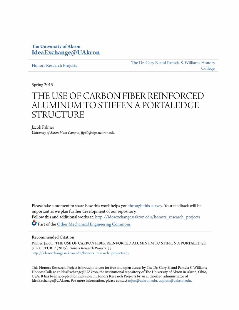
Abstract Increased stiffness will be achieved through a unidirectional carbon fiber tube that will encase
the aluminum tubing. This will give the structure the stiffness it needs to resist bending enabling the elimination of the spreader bar, while still maintaining the ductile material properties of the
6061 T-6 aluminum.
P a g e | 1
Contents Introduction .................................................................................................................................................. 2
Assembly Process .......................................................................................................................................... 3
Executive Summary ....................................................................................................................................... 4
Design Objectives .......................................................................................................................................... 4
Design Process .............................................................................................................................................. 4
Background ................................................................................................................................................... 5
Materials and Experimental Procedure ........................................................................................................ 7
Figure1: Test setup ................................................................................................................................ 7
Calculations ................................................................................................................................................... 8
Assumptions .............................................................................................................................................. 8
Results ......................................................................................................................................................... 11
FEA Models ............................................................................................................................................. 11
Figure 2: 6061 T-6 aluminum’s deflection .......................................................................................... 11
Figure 3: Carbon Fiber tubing deflection ............................................................................................ 11
Figure 4: 6061 T-6 aluminum’s bending stress ................................................................................... 12
Figure 5: Carbon Fiber tubing bending stress ..................................................................................... 12
Loading Of Test Members ....................................................................................................................... 13
Figure 6: .............................................................................................................................................. 13
Figure 7: .............................................................................................................................................. 13
Figure 8: .............................................................................................................................................. 13
Graph 1: .............................................................................................................................................. 14
Temperature Testing............................................................................................................................... 15
Discussion of Results ................................................................................................................................... 16
Conclusion ................................................................................................................................................... 16
P a g e | 2
Introduction Throughout history, climbers have always wanted to climb bigger and better things but have been
limited by the time needed to complete these climbs. Without any natural ledges to sleep on, many big
shear walls that seemed unsurmountable were left unclimbed like those in Yosemite. Something
needed to be designed to help them conquer these daunting feats. This is when the portaledge was
designed.
A portaledge is exactly what it sounds like. It is a portable ledge that climbers set up while hanging from
the wall, giving them a place to rest and sleep. This allows a climber to spend days or even weeks up on
a wall, and enables them to try unclimbed big walls. The design for a portaledge is very simple, it is eight
bars of 6061 t-6 aluminum, each 3 feet long in length that snap together via corner joints and sleeves.
All of these components are attached to each other via a bungee cord material such as that seen in tent
poles, just thicker. Once these tubes have been inserted in, the whole frame is supported by webbing
that comes off of each corner joint that has a bolt and the sleeve which has a nylon wrap that goes
around it. This webbing then goes to a main anchor point that is attached to the wall. This can be better
seen in the assembly process section of this report. After assembling the frame, a 420D ripstop nylon
fabric is stretched between each member and is tensioned between the bars to create the platform on
which a climber sleeps. To keep the frame from bending in, a spreader bar is used to exert force on the
longer side walls at the sleeve location. This design has stayed relatively unchanged since it was first
created. This is because it is a simple design and a simple design is the name of the game when it comes
to being high up on a big wall or in the mountains. Every moving part is a chance for something to go
wrong. Dirt can get into the moving mechanisms and clog them up and more moving parts normally
equates to more weight as well. It is also important to keep it simple because if something goes wrong, a
climber does not carry any tools to fix it. This can be life threatening when hanging a couple thousand
feet above the ground.
So how does one improve upon a design that is already very simple and has proven to be reliable for
years now? Even though this old design has been around for a while, there are some issues and
downsides to the design. These issues with current designs are that they are heavy, very cumbersome
for one person to assemble, and hard to adjust the webbing that make the ledge level. As stated earlier,
portaledges use aluminum for the framing which, although lighter than most materials, can still add up
to a very heavy load to have to drag up a couple thousand feet. In addition to the weight of the framing,
there is a large spreader bar that not only is heavy, but it is by far the hardest part of a portaledge to
assemble. To get the spreader bar on to the frame, someone has to simultaneously hold the large frame
while trying to bend this large piece into its position. This can sometimes feel near impossible after 18
hours straight of climbing. As far as leveling the portaledge, there are individual adjustment straps that
go out to all of the anchor points and must be adjusted until the ledge is properly leveled and equally
tensioned on each line.
In the next section, that assembly process will be discussed to provide a greater overview and
understanding of the portaledge system before continuing on with the design process and testing. This
should help the reader to know how the system works as a whole.
P a g e | 3
Assembly Process
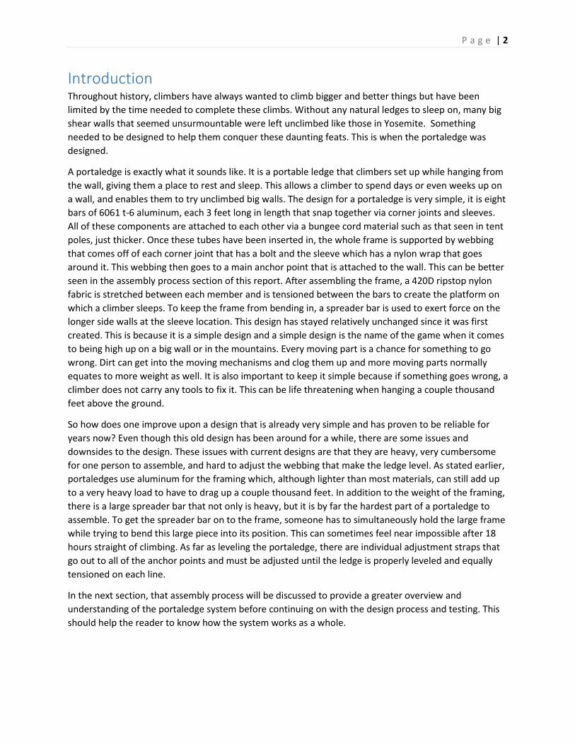
At 3 of the corners, the tubes slide into circular
channels. This corner block will be supported
through the attached bolt that will use webbing to
go up to the central Anchor point.
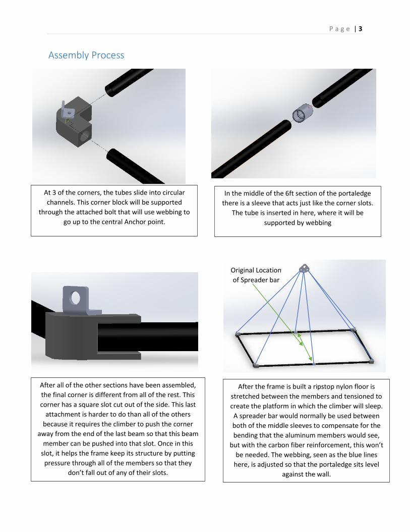
In the middle of the 6ft section of the portaledge
there is a sleeve that acts just like the corner slots.
The tube is inserted in here, where it will be
supported by webbing
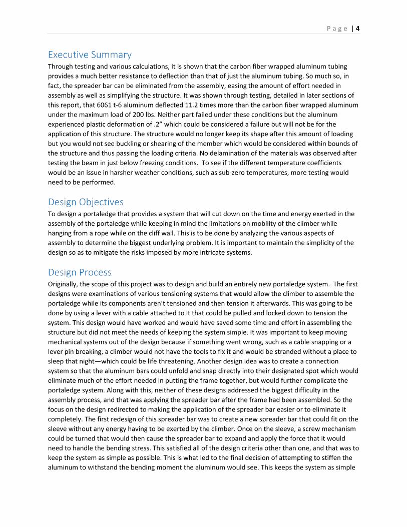
After all of the other sections have been assembled,
the final corner is different from all of the rest. This
corner has a square slot cut out of the side. This last
attachment is harder to do than all of the others
because it requires the climber to push the corner
away from the end of the last beam so that this beam
member can be pushed into that slot. Once in this
slot, it helps the frame keep its structure by putting
pressure through all of the members so that they
don’t fall out of any of their slots.
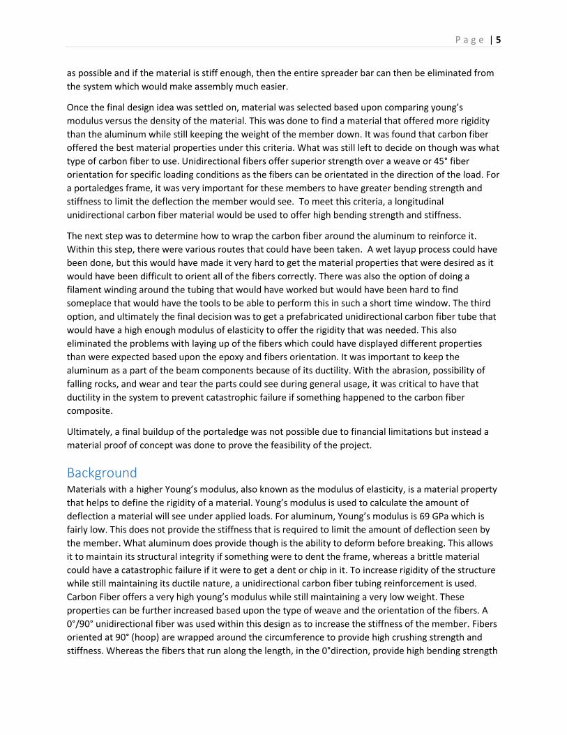
After the frame is built a ripstop nylon floor is
stretched between the members and tensioned to
create the platform in which the climber will sleep.
A spreader bar would normally be used between
both of the middle sleeves to compensate for the
bending that the aluminum members would see,
but with the carbon fiber reinforcement, this won’t
be needed. The webbing, seen as the blue lines
here, is adjusted so that the portaledge sits level
against the wall.
Original Location
of Spreader bar
P a g e | 4
Executive Summary Through testing and various calculations, it is shown that the carbon fiber wrapped aluminum tubing
provides a much better resistance to deflection than that of just the aluminum tubing. So much so, in
fact, the spreader bar can be eliminated from the assembly, easing the amount of effort needed in
assembly as well as simplifying the structure. It was shown through testing, detailed in later sections of
this report, that 6061 t-6 aluminum deflected 11.2 times more than the carbon fiber wrapped aluminum
under the maximum load of 200 lbs. Neither part failed under these conditions but the aluminum
experienced plastic deformation of .2” which could be considered a failure but will not be for the
application of this structure. The structure would no longer keep its shape after this amount of loading
but you would not see buckling or shearing of the member which would be considered within bounds of
the structure and thus passing the loading criteria. No delamination of the materials was observed after
testing the beam in just below freezing conditions. To see if the different temperature coefficients
would be an issue in harsher weather conditions, such as sub-zero temperatures, more testing would
need to be performed.
Design Objectives To design a portaledge that provides a system that will cut down on the time and energy exerted in the
assembly of the portaledge while keeping in mind the limitations on mobility of the climber while
hanging from a rope while on the cliff wall. This is to be done by analyzing the various aspects of
assembly to determine the biggest underlying problem. It is important to maintain the simplicity of the
design so as to mitigate the risks imposed by more intricate systems.
Design Process Originally, the scope of this project was to design and build an entirely new portaledge system. The first
designs were examinations of various tensioning systems that would allow the climber to assemble the
portaledge while its components aren’t tensioned and then tension it afterwards. This was going to be
done by using a lever with a cable attached to it that could be pulled and locked down to tension the
system. This design would have worked and would have saved some time and effort in assembling the
structure but did not meet the needs of keeping the system simple. It was important to keep moving
mechanical systems out of the design because if something went wrong, such as a cable snapping or a
lever pin breaking, a climber would not have the tools to fix it and would be stranded without a place to
sleep that night—which could be life threatening. Another design idea was to create a connection
system so that the aluminum bars could unfold and snap directly into their designated spot which would
eliminate much of the effort needed in putting the frame together, but would further complicate the
portaledge system. Along with this, neither of these designs addressed the biggest difficulty in the
assembly process, and that was applying the spreader bar after the frame had been assembled. So the
focus on the design redirected to making the application of the spreader bar easier or to eliminate it
completely. The first redesign of this spreader bar was to create a new spreader bar that could fit on the
sleeve without any energy having to be exerted by the climber. Once on the sleeve, a screw mechanism
could be turned that would then cause the spreader bar to expand and apply the force that it would
need to handle the bending stress. This satisfied all of the design criteria other than one, and that was to
keep the system as simple as possible. This is what led to the final decision of attempting to stiffen the
aluminum to withstand the bending moment the aluminum would see. This keeps the system as simple
P a g e | 5
as possible and if the material is stiff enough, then the entire spreader bar can then be eliminated from
the system which would make assembly much easier.
Once the final design idea was settled on, material was selected based upon comparing young’s
modulus versus the density of the material. This was done to find a material that offered more rigidity
than the aluminum while still keeping the weight of the member down. It was found that carbon fiber
offered the best material properties under this criteria. What was still left to decide on though was what
type of carbon fiber to use. Unidirectional fibers offer superior strength over a weave or 45° fiber
orientation for specific loading conditions as the fibers can be orientated in the direction of the load. For
a portaledges frame, it was very important for these members to have greater bending strength and
stiffness to limit the deflection the member would see. To meet this criteria, a longitudinal
unidirectional carbon fiber material would be used to offer high bending strength and stiffness.
The next step was to determine how to wrap the carbon fiber around the aluminum to reinforce it.
Within this step, there were various routes that could have been taken. A wet layup process could have
been done, but this would have made it very hard to get the material properties that were desired as it
would have been difficult to orient all of the fibers correctly. There was also the option of doing a
filament winding around the tubing that would have worked but would have been hard to find
someplace that would have the tools to be able to perform this in such a short time window. The third
option, and ultimately the final decision was to get a prefabricated unidirectional carbon fiber tube that
would have a high enough modulus of elasticity to offer the rigidity that was needed. This also
eliminated the problems with laying up of the fibers which could have displayed different properties
than were expected based upon the epoxy and fibers orientation. It was important to keep the
aluminum as a part of the beam components because of its ductility. With the abrasion, possibility of
falling rocks, and wear and tear the parts could see during general usage, it was critical to have that
ductility in the system to prevent catastrophic failure if something happened to the carbon fiber
composite.
Ultimately, a final buildup of the portaledge was not possible due to financial limitations but instead a
material proof of concept was done to prove the feasibility of the project.
Background Materials with a higher Young’s modulus, also known as the modulus of elasticity, is a material property
that helps to define the rigidity of a material. Young’s modulus is used to calculate the amount of
deflection a material will see under applied loads. For aluminum, Young’s modulus is 69 GPa which is
fairly low. This does not provide the stiffness that is required to limit the amount of deflection seen by
the member. What aluminum does provide though is the ability to deform before breaking. This allows
it to maintain its structural integrity if something were to dent the frame, whereas a brittle material
could have a catastrophic failure if it were to get a dent or chip in it. To increase rigidity of the structure
while still maintaining its ductile nature, a unidirectional carbon fiber tubing reinforcement is used.
Carbon Fiber offers a very high young’s modulus while still maintaining a very low weight. These
properties can be further increased based upon the type of weave and the orientation of the fibers. A
0°/90° unidirectional fiber was used within this design as to increase the stiffness of the member. Fibers
oriented at 90° (hoop) are wrapped around the circumference to provide high crushing strength and
stiffness. Whereas the fibers that run along the length, in the 0°direction, provide high bending strength
P a g e | 6
and stiffness (ACP Composites, 2015). Within the composite tubing that was ordered for testing, around
75% of the fibers ran longitudinally along the tube.The reason that the direction of the fibers is
important within the material is because carbon fiber is anisotropic. This means that the material
properties are very different depending on what orientation they are in.
P a g e | 7
Materials and Experimental Procedure Materials:
Two 3 foot long sections of 6061 t-6 Aluminum tubing
3 foot long section of 0°/90° unidirectional carbon fiber tubing
200 lbs worth of weights
8 cinder blocks
Cordellette
Webbing
A marker
Ruler
Aluminum master point plate
4 carabiners
Experimental Procedure:
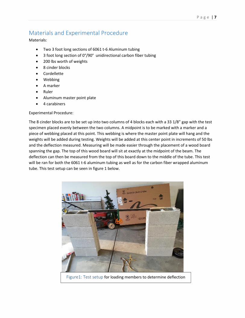
The 8 cinder blocks are to be set up into two columns of 4 blocks each with a 33 1/8” gap with the test
specimen placed evenly between the two columns. A midpoint is to be marked with a marker and a
piece of webbing placed at this point. This webbing is where the master point plate will hang and the
weights will be added during testing. Weights will be added at this center point in increments of 50 lbs
and the deflection measured. Measuring will be made easier through the placement of a wood board
spanning the gap. The top of this wood board will sit at exactly at the midpoint of the beam. The
deflection can then be measured from the top of this board down to the middle of the tube. This test
will be ran for both the 6061 t-6 aluminum tubing as well as for the carbon fiber wrapped aluminum
tube. This test setup can be seen in figure 1 below.
Figure1: Test setup for loading members to determine deflection
P a g e | 8
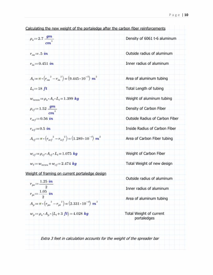
Calculations
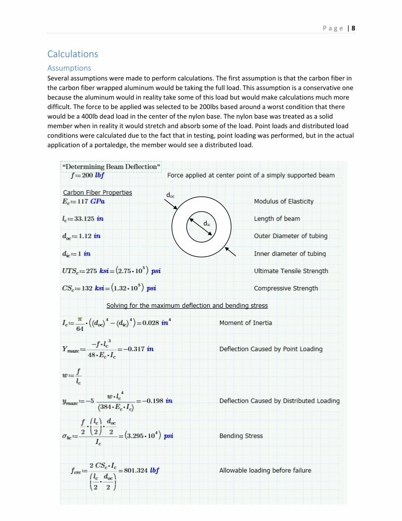
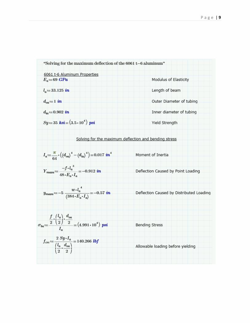
Assumptions Several assumptions were made to perform calculations. The first assumption is that the carbon fiber in
the carbon fiber wrapped aluminum would be taking the full load. This assumption is a conservative one
because the aluminum would in reality take some of this load but would make calculations much more
difficult. The force to be applied was selected to be 200lbs based around a worst condition that there
would be a 400lb dead load in the center of the nylon base. The nylon base was treated as a solid
member when in reality it would stretch and absorb some of the load. Point loads and distributed load
conditions were calculated due to the fact that in testing, point loading was performed, but in the actual
application of a portaledge, the member would see a distributed load.
doc
dic
P a g e | 9
P a g e | 10
P a g e | 11
Results
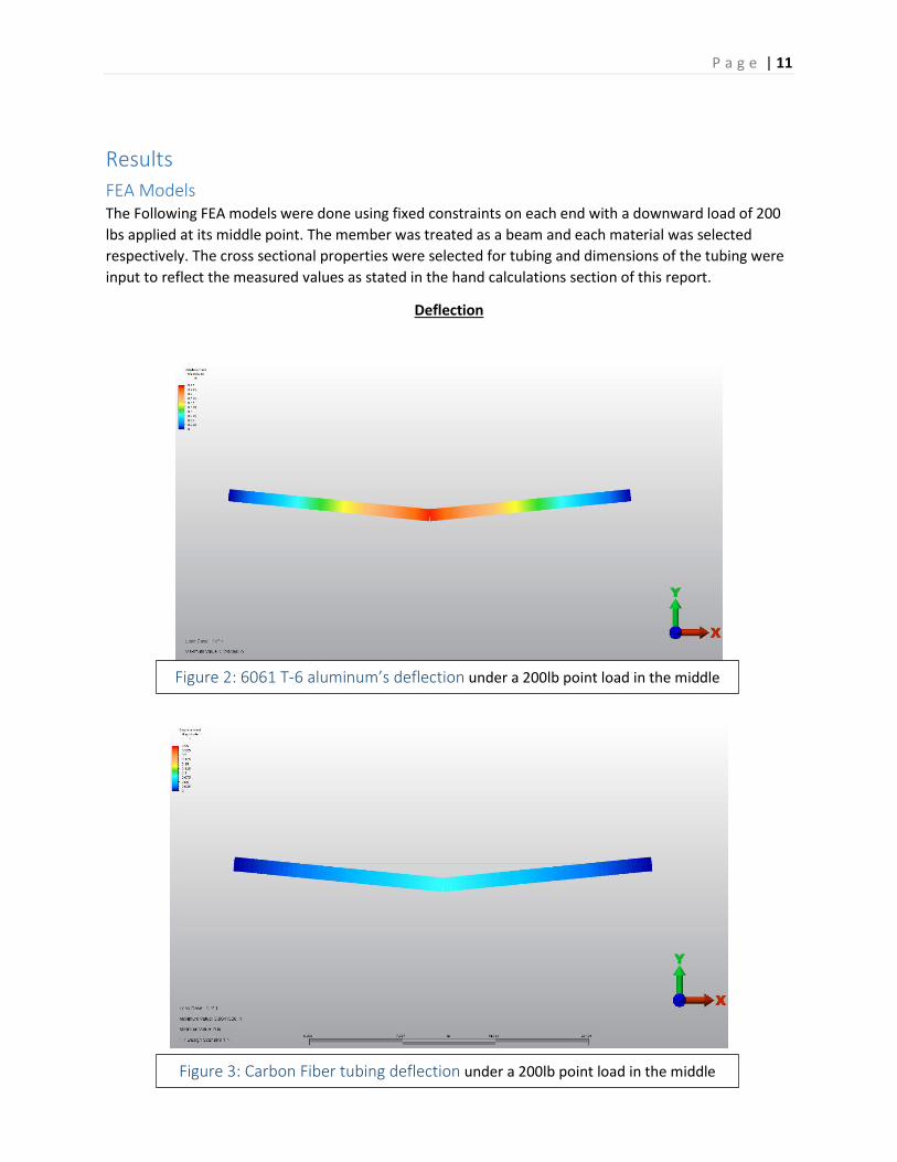
FEA Models The Following FEA models were done using fixed constraints on each end with a downward load of 200
lbs applied at its middle point. The member was treated as a beam and each material was selected
respectively. The cross sectional properties were selected for tubing and dimensions of the tubing were
input to reflect the measured values as stated in the hand calculations section of this report.
Deflection
Figure 2: 6061 T-6 aluminum’s deflection under a 200lb point load in the middle
Figure 3: Carbon Fiber tubing deflection under a 200lb point load in the middle
P a g e | 12
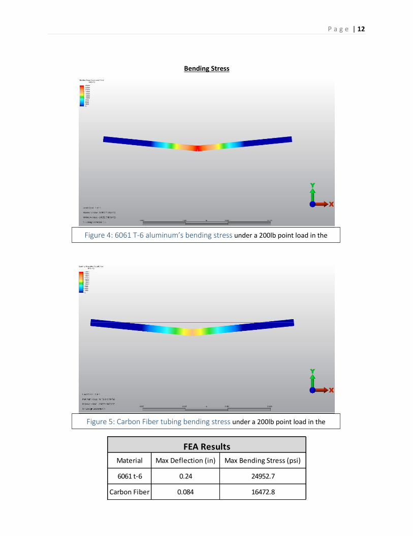
Material Max Deflection (in) Max Bending Stress (psi)
6061 t-6 0.24 24952.7
Carbon Fiber 0.084 16472.8
FEA Results
Bending Stress
Figure 4: 6061 T-6 aluminum’s bending stress under a 200lb point load in the
middle
Figure 5: Carbon Fiber tubing bending stress under a 200lb point load in the
middle
P a g e | 13
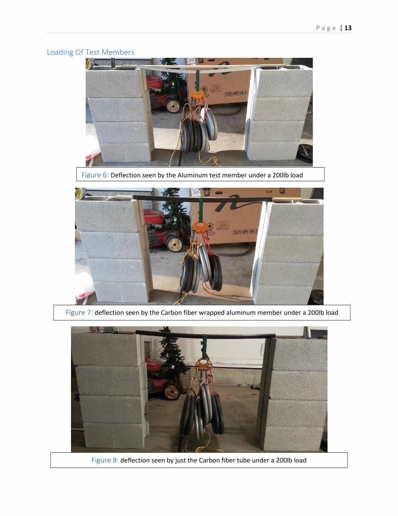
Loading Of Test Members
Figure 6: Deflection seen by the Aluminum test member under a 200lb load
Figure 7: deflection seen by the Carbon fiber wrapped aluminum member under a 200lb load
Figure 8: deflection seen by just the Carbon fiber tube under a 200lb load
P a g e | 14
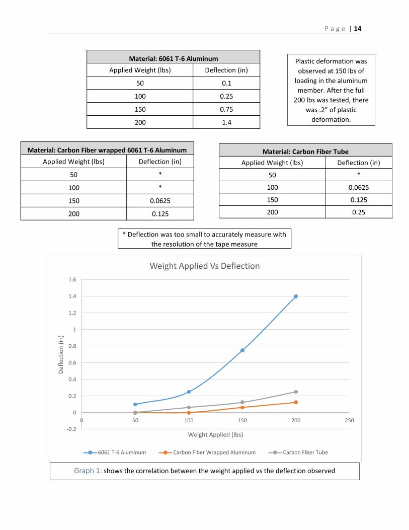
Applied Weight (lbs) Deflection (in)
50 0.1
100 0.25
150 0.75
200 1.4
Material: 6061 T-6 Aluminum
Applied Weight (lbs) Deflection (in)
50 *
100 *
150 0.0625
200 0.125
Material: Carbon Fiber wrapped 6061 T-6 Aluminum
Applied Weight (lbs) Deflection (in)
50 *
100 0.0625
150 0.125
200 0.25
Material: Carbon Fiber Tube
* Deflection was too small to accurately measure with
the resolution of the tape measure
-0.2
0
0.2
0.4
0.6
0.8
1
1.2
1.4
1.6
0 50 100 150 200 250
Def
lect
ion
(in
)
Weight Applied (lbs)
Weight Applied Vs Deflection
6061 T-6 Aluminum Carbon Fiber Wrapped Aluminum Carbon Fiber Tube
Graph 1: shows the correlation between the weight applied vs the deflection observed
Plastic deformation was
observed at 150 lbs of
loading in the aluminum
member. After the full
200 lbs was tested, there
was .2” of plastic
deformation.
P a g e | 15
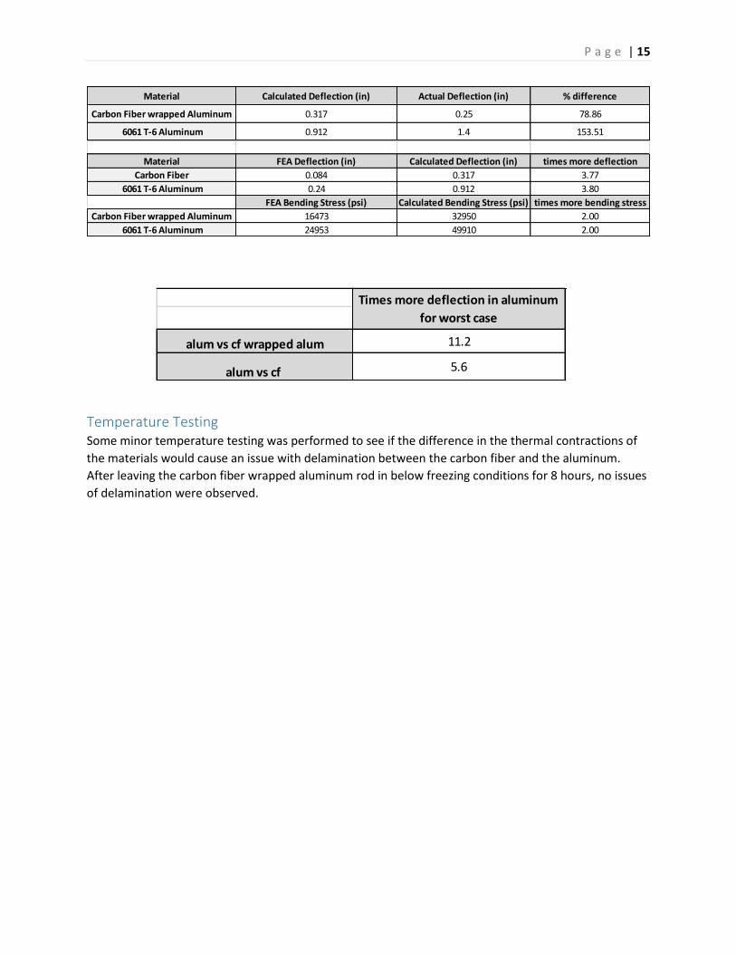
alum vs cf wrapped alum 11.2
alum vs cf 5.6
Times more deflection in aluminum
for worst case
Material Calculated Deflection (in) Actual Deflection (in) % difference
Carbon Fiber wrapped Aluminum 0.317 0.25 78.86
6061 T-6 Aluminum 0.912 1.4 153.51
Material FEA Deflection (in) Calculated Deflection (in) times more deflection
Carbon Fiber 0.084 0.317 3.77
6061 T-6 Aluminum 0.24 0.912 3.80
FEA Bending Stress (psi) Calculated Bending Stress (psi) times more bending stress
Carbon Fiber wrapped Aluminum 16473 32950 2.00
6061 T-6 Aluminum 24953 49910 2.00
Temperature Testing Some minor temperature testing was performed to see if the difference in the thermal contractions of
the materials would cause an issue with delamination between the carbon fiber and the aluminum.
After leaving the carbon fiber wrapped aluminum rod in below freezing conditions for 8 hours, no issues
of delamination were observed.
P a g e | 16
Discussion of Results Through the actual loading of the test materials, some differences can be noticed between the actual
performances of the materials versus the theoretical calculations. First, it was seen that the actual
deflection was around 79% of the calculated deflection that the member would see. This could be due
to more fibers being oriented in the longitudinal direction than was specified in the material spec which
would increase the bending strength. The aluminum on the other hand was 153% more than the
calculated deflection. This was more than likely caused by the fact that once a material exceeds its yield
strength, it no longer elastically deforms. This should have occurred around 150 lbs of load. This can be
observed in graph 1 when there is an observable spike in the amount of deflection at this point. After
this yielding occurred, the part had .2” of plastic deformation once the final load of 200 lbs was
removed. It should be noted though that discrepancies could be present in the actual testing values for
deflection due to the resolution of the measuring device. If testing were to be done again, a more
accurate means of measuring should be implemented such as the use of calipers.
From comparing the deflection of the carbon fiber wrapped aluminum and just the carbon fiber tube, an
interesting observation can be made. The carbon fiber wrapped aluminum had almost exactly half of the
amount of deflection as that of just the carbon fiber tube. That means that the aluminum tubing inside
of the carbon fiber significantly helps to resist the deformation caused by bending within the member.
So the aluminum not only provides the ductility that is needed, but also increases rigidity within the
member. Therefore the original assumption that the carbon fiber would take the full load was a much
more conservative assumption than first thought.
Looking at the FEA models, the values that were found within the program, both for the deflection and
bending stress, were very different from the calculated deflection as well as the actual deflection. The
bending stresses calculated were both twice the amount as that in the FEA model and the calculated
deflections were both just about 3.8 times bigger than the FEA model. These errors seem to have
arrived somewhere within the FEA model as the calculated deflection was much closer to the actual
testing values. Along with this, the amount of weight it took to be applied before the aluminum started
to yield, which was around 150 lbs, all coincide with the hand calculations that were performed.
Conclusion The carbon fiber wrapped aluminum provides the sufficient amount of stiffness and strength to
adequately limit the amount of deflection. With this increased stiffness, the spreader bar will be able to
be eliminated which ultimately will make the whole assembly process easier and cut down on the
assembly time significantly. Along with the increased stiffness, the carbon fiber also provides the
structure with the material properties to withstand more force before failing. This provides the
portaledge with an even higher factor of safety for the climber when being used in ever harsher
environments. Lastly, the new design cuts down on the weight of the original design by about 1.6kg
which