Embed Size (px)
Citation preview
THE UNIVERSITY OF HONG KONGLIBRARIES
This book was receivedin accordance with the Books
Registration OrdinanceSection 4
DRAFT CODE OF PRACTICE
FOR
DEMOLITION OF BUILDINGS
February 1998
BOOKS REGISTRATION ORDINANCEChapter 142
No.: HK984904 fg

£'2

Foreword
There has been increase in building demolition activities in Hong Kong as morebuildings erected in the 60 9s and 70 ?s are put down to give way for new developmentsin busy urban areas. Nowadays, buildings to be demolished include high-risebuildings of various structural forms and construction materials. Better planning,control, and selection of the appropriate demolition method and precautionarymeasures are required to cope with the increasing size and complexity of buildings tobe demolished.
Demolition is a skilled and potentially dangerous operation. This draft Code is Issuedto provide guidance on safe and good practices for demolition works and forcompliance with the requirements of the relevant provisions of the Building(Administration) Regulations and Building (Demolition Works) Regulations relatingto demolition works. Therefore, this draft Code should be read and used inconjunction with the Buildings Ordinance and the aforesaid Regulations whenpreparing demolition plans for approval by the Building Authority.
This draft Code includes basic Information for consideration of selecting theappropriate method of demolition of different types of structures and provides a basisfor a logical approach to safe procedures and advice on safety precautions. Themethods of demolition covered in this code are for the consideration of practitioners inplanning their demolition works. Practitioners must exercise their own professionaljudgement when selecting the most suitable method, taking into account the particularconstruction condition, previous use and age of the structure to be demolished, and thespecial conditions of the site and its surroundings to ensure safety. Practitioners5
attention is drawn to the relevant provisions of the Buildings Ordinance andRegulations requiring the submission of demolition plan and obtaining the approval ofthe Building Authority for the demolition method adopted in each case.
This draft Code is now Issued as a draft document for trial use for a period of one year.It will be replaced by a finalised edition when it has been reviewed through experiencegained in its application.
Comments to improve the draft Code are welcome and should be sent to the Legal andManagement Division of the Buildings Department.
Buildings Department
First issue : February 1998
Table of Contents
Table of Contents
1. GENERAL 1
1.1 Scope 1
1.2 Definitions 1
2. PLANNING 4
2.1 Building Appraisal and Demolition Plan 4
2.2 Utilities 10
3. PRECAUTIONARY MEASURES 12
3.1 General 12
3.2 Hoarding and Covered Walkway 12
3.3 Scaffoldings and Screen Covers 20
3.4 Catchfan 23
3.5 Temporary Supports 26
3.6 Protection of Properties 33
3.7 Protection of Traffic 35
3.8 Special Safety Considerations 35
3.9 Environmental Precautions 38
3.10 Debris and Waste Handling 39
3.11 Inspection and Maintenance 42
3.12 Post-Demolition Precautions 43
4. METHODS OF DEMOLITION 45
4.1 General 45
4.2 Top-Down Methods 45
4.3 Mechanical by Hydraulic Crushers with LongBoom Arm 77

Table of Contents
Table of Contents (Cont'd)
4.4 Wrecking Ball 79
4.5 Implosion 83
4.6 Other Methods 85
5. SPECIAL STRUCTURES 94
5.1 Precast Concrete Structures 94
5.2 Prestressed Concrete Structures 96
5.3 Statically Determinate Structures 103
5.4 Composite Structures and Steel Structures 104
5.5 Cladding Walls 106
5.6 Hanging Structures 107
5.7 Oil Storage Facilities 107
5.8 Marine Structures 109
5.9 Underground Structures 110
5.10 Structures Supporting Ground or Sitting on Slopes 112
6. SITE SUPERVISION AND INSPECTION 114
6.1 General 114
Appendix A DEMOLITION CHECKLIST Al
B DEMOLITION PLAN CHECKLIST Bl
C PRESTRESSED CONCRETE AND GUIDELINES FORIDENTIFICATION Cl
D REGULATIONS RELATING TO DEMOLITIONPROJECTS Dl
E NOTIFICATIONS AND PROCEDURES El
F EXAMPLE OF DEMOLITION AND STABILITY REPORT FlFOR TOP DOWN MANUAL METHOD

Table of Contents
Table of Contents (Cont'd)
G EXAMPLE OF DEMOLITION PLAN AND STABILITY G1REPORT FOR TOP DOWN METHOD WITH MACHINE
H FLOW CHART FOR CURRENT DEMOLITIONPROCEDURE IN HONG KONG H1
m
List of Tables
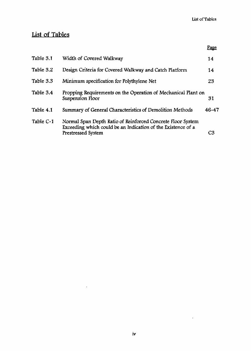
List of Tables
Table 3.1
Table 3.2
Table 3.3
Table 3.4
Table 4.1
Table C-l
Width of Covered Walkway
Design Criteria for Covered Walkway and Catch Platform
Minimum specification for Polythylene Net
14
14
23
Propping Requirements on the Operation of Mechanical Plant onSuspension Floor 31
Summary of General Characteristics of Demolition Methods 46-47
Normal Span Depth Ratio of Reinforced Concrete Floor SystemExceeding which could be an Indication of the Existence of aPrestressed System C3
IV
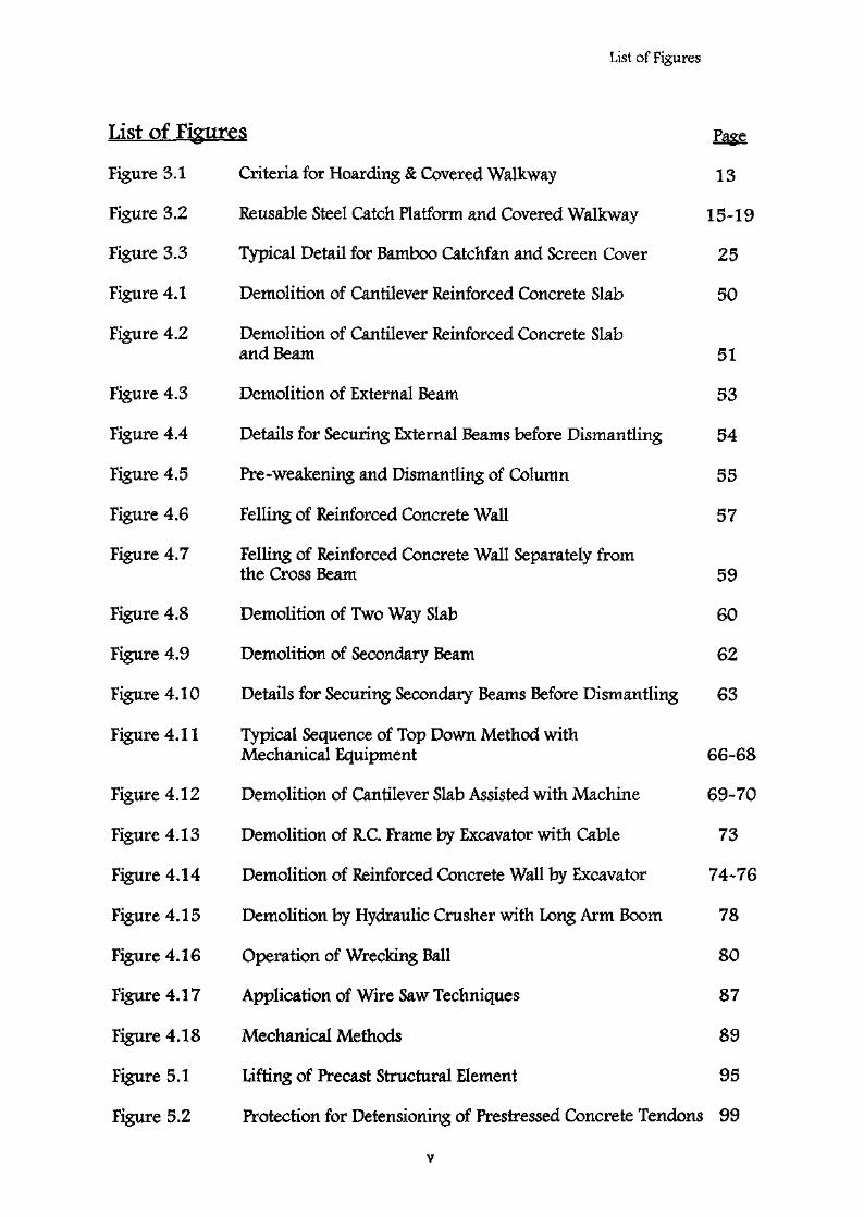
List of Figures
List of
Figure 3.1 Criteria for Hoarding & Covered Walkway 13
Figure 3.2 Reusable Catch Platform and Covered Walkway 15-19
Figure 3.3 Typical Detail for Bamboo Catchfan and Screen Cover 25
Figure 4.1 Demolition of Cantilever Reinforced Concrete Slab 50
Figure 4.2 Demolition of Cantilever Reinforced Concrete Slaband Beam 51
Figure 4.3 Demolition of External Beam 53
Figure 4.4 Details for Securing External Beams before Dismantling 54
Figure 4.5 Pre-weakening and Dismantling of Column 55
Figure 4.6 Felling of Reinforced Concrete Wall 57
Figure 4.7 Felling of Reinforced Concrete Wall Separately fromthe Cross Beam 59
Figure 4.8 Demolition of Two Way Slab 60
Figure 4.9 Demolition of Secondary Beam 62
Figure 4.10 Details for Securing Secondary Beams Before Dismantling 63
Figure 4.11 Typical Sequence of Top Down Method withMechanical Equipment 66*68
Figure 4.12 Demolition of Cantilever Slab Assisted with Machine 69-70
Figure 4.13 Demolition of R.C. Frame by Excavator with Cable 73
Figure 4.14 Demolition of Reinforced Concrete Wall by Excavator 74-76
Figure 4.15 Demolition by Hydraulic Crusher with Long Arm Boom 78
Figure 4.16 Operation of Wrecking Ball 80
Figure 4.17 Application of Wire Saw Techniques 87
Figure 4.18 Mechanical Methods 89
Figure 5.1 Lifting of Precast Structural Element 95
Figure 5.2 Protection for Detensioning of Prestressed Concrete Tendons 99
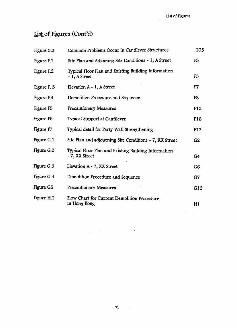
List of Figures
List of Figures (Confd)
Figure 5.3 Common Problems Occur in Cantilever Structures
Figure F. 1 Site Plan and Adjoining Site Conditions - 1, A Street
Figure F.2 Typical Floor Plan and Existing Building Information- 1, A Street
Figure F. 3 Elevation A -1, A Street
Figure F.4 Demolition Procedure and Sequence
Figure F5 Precautionary Measures
Figure F6 Typical Support at Cantilever
Figure F7 Typical detail for Party Wall Strengthening
Figure G.I Site Plan and adjourning Site Conditions - 7, XX Street
Figure G.2 Typical Floor Plan and Existing Building Information- 7, XX Street
Figure G.3 Elevation A - 7, XX Street
Figure G.4 Demolition Procedure and Sequence
Figure G5 Precautionary Measures
Figure H. 1 Flow Chart for Current Demolition Procedurein Hong Kong
105
F3
F5
F7
F8
F12
F16
F17
G2
G4
G6
G7
G12
HI
VI

1.1
1.1.1 This Code of Practice outlines good practices for andimplementation of demolition of various building works in Hong Kongaiming at minimising the following risks:
(A) Damage to persons and properties of the public;
(B) Endanger the health and safety of site personnel; and
(C) Damage to the neighbourhood environment
The prime intention of this Code is to give guidelines for engineeringpractice and safe procedures for various demolition methods and toprovide guidance on compliance with relevant requirements of Building(Administration) Regulations and Building (Demolition Works)Regulations. Aspects related to environmental, labour health and safetyare referenced to relevant regulations.
1.1.2 This Code sets out the guidelines for demolition of buildings. ThisCode is applicable to individual structures, partial demolition ofbuildings, basements, underground tanks, and common civilengineering structures, e.g., silos, industrial plants, piers, etc. However,this Code is not intended to cover major civil engineering works, suchas underpinning, excavation, highway or railway bridges, dams andnuclear reactors.
1.1.3 This Code covers methods commonly used in building demolition.Though it does not include all demolition methods, it is not theintention to discourage the use of other methods which are not includedin this Code. Any newly invented demolition method not covered inthis Code may be used subject to careful consideration andrecommendation by experienced Authorized Person, RegisteredStructural Engineer and Registered Specialist Demolition Contractor,or their equivalent professionals or counterparts and subject to theapproval of the Building Authority or other equivalent approvingAuthority. Such new demolition method proposed shall be supportedby scientific research and engineering experience.
1.2 Definitions
For the purpose of this Code, the following definitions shall apply:

a whose Is on the Authorizedpersons' kept 3(1):
(a) as an architect; or
(b) as an engineer; or
(c) as a surveyor;
Expert" means a person who is the holder of a valid mine blastingcertificate or a special by the Commissioner of Minespursuant to Dangerous Goods (General) Regulations 47.
66Buildieg means the vertical distance measured from the top mostpart of the building to be demolished to the lowest ground level;
"Building Survey** means an inspection on the Building and its surroundingsaiming at spotting any potential problems that may arise during demolition anddeveloping a Method Statement for Demolition;
"Catch. Platform" is a temporary structure erected on top of the coveredwalkway or underneath structures that are being demolished including, but notlimited to, balconies and cantilever structures for the purpose of catching andretaining debris and to protect the area beneath such structures beingdemolished;
"Catchfan" is a temporary structure, generally, installed at an inclined angle,and is erected around, attached or abutting the exterior wall of the buildingbeing demolished for the purpose of catching and retaining debris that falloutside the building;
"Covered Walkway" means a temporary structure with protective rooferected along the site boundary and on or adjacent to the existing footpath toprotect the pedestrian from the falling debris during demolition;
"Demolition" means dismantling, razing, destroying or wrecking any buildingor structure or any part thereof by pre-planned and controlled methods;
"Demolition Plan95 is one of the prescribed plans stated in the Building(Administration) Regulation, and its contents are stated in Building(Administration) Regulation 8(3).
"Hanging Structure" means unconventional structure that is supported fromthe top by tension members such as suspended cables, tie rods or other means;
"Hoarding" means a temporary fence enclosure erected along the siteboundary to separate the demolition site from the adjacent properties;
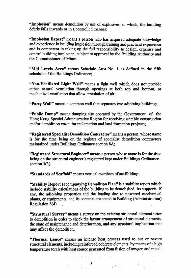
demolition by use of explosives, in which, the buildingdebris or in a controlled manner;
a person who has acquired adequate knowledgeand experience in implosion through training and practical experienceand Is competent in up the full responsibility to design, organise andcontrol implosion, subject to approval by the Building Authority andthe Commissioner of Mines.
Area9* means Schedule Area No. 1 as defined in the fifthschedule of the Buildings Ordinance;
Light WelP means a light well which does not provideeither natural ventilation through openings at both top and bottom, ormechanical ventilation that allow circulation of air;
"Party WaiP means a common wall that separates two adjoining buildings;
"Public Dumpff means dumping site operated by the Government of theHong Kong Special Administrative Region for receiving suitable constructionand/or demolition waste for reclamation and land formation projects;
"Registered Specialist Demolition Contractor" means a person whose nameis for the time being on the register of specialist demolition contractorsmaintained under Buildings Ordinance section 8A;
"Registered Structural Engineer" means a person whose name is for the timebeing on the structural engineer's registered kept under Buildings Ordinancesection 3(3);
"Standards of Scaffold" means vertical members of scaffolding;
"Stability Report accompanying Demolition Plan" is a stability report whichinclude stability calculations of the building to be demolished, its supports, ifany, the adjoining properties and the loading due to powered mechanicalplants, or equipments, and its contents are stated in Building (Administration)Regulation 8(4).
"Structural Survey" means a survey on the existing structural element priorto demolition in order to check the layout arrangement of structural elements,the state of maintenance and deterioration, and any structural implication thatmay affect the demolition;
"Thermal l^ance" means an intense heat process used to cut or severestructural elements, including reinforced concrete elements, by means of a hightemperature torch with heat source generated from fusion of oxygen and metal.
2.
2.1
Prior to cajryiiig out any building demolition, detailed building appraisal bymeans of surveys and appropriate assessments shall be required. In general,the surveys shall include a Building Survey and a Structural Survey withphotographs or videos taken for future reference. Based on the findings ofthese surveys, a demolition plan shall then be prepared and submitted to theBuildings Department for approval. The demolition plan must also beaccompanied by a report together with structural calculations assessing thestability of the building to be demolished and all affected buildings, structures,streets, land and services.
2.1.1 Building Survey
(A) Record Drawings
Prior to the Building Survey, the existing record plan, includinglayout plan showing adjoining properties, pedestrian walkway,roads and street, etc. shall be retrieved.
(B) Survey Items
The Building Survey shall cover the following:
(1) The construction materials;
(2) The existing use and, if possible, the past uses of thebuilding prior to demolition;
(3) The presence of wastewater, hazardous materials, mattersarising from toxic chemicals, flammable or explosive andradioactive materials, etc. and possible presence ofmaterials which can contribute to air pollution and soilcontamination;
(4) Potential dangerous areas, e.g., abnormal layouts, presenceof enclosed voids, and non-ventilated light wells whichmay trap obnoxious gas at the bottom;
(5) Adjoining properties and site conditions, such as theexistence of slope and retaining wall, wall supportingground* illegal structures, bridges, uiiderground railwayand its above ground structures, including entrances, vent
4

shafts, substations,plantrooms, overhead railway structures, surface track
' sections, overhead cables or guy wires, and other utilityservice connections;
(6) Drainage conditions and possible on waterpollution, flooding and erosion, especially on sloping sitesand water receiving bodies;
(7) Shared facilities with adjoining building, includmgcommon staircases, party walls, and possible effect on it,such as self-enclosed walls to the adjoining buildings,during demolition;
(8) Hoarding and covered walkway requirements;
(9) Adjoining pedestrian and vehicular traffic conditions;
(10) Available headroom, clear spaces and distance of buildingfrom lot boundary which may affect the loading operationand transportation of building debris during demolition;
(11) The sensitivity of neighbourhood with respect to noise,dust, vibration and traffic impact;
(12) Available site area to allow on-site sorting of buildingdebris;
(13) Street furniture such as fire hydrant, parking space/metres,street light, street sign, hawker and stalls which could beaffected by the demolition project
(C) Hazardous Materials
(1) Unless the Building Survey reviews that no obvioushazardous material is present in the building, theAuthorized Person shall cause proper sampling and testingfor the hazardous materials;
(2) In the case when hazardous materials are present, suchhazardous materials e.g., asbestos containing materials, orpetroleum, shall be removed and cleaned according to thestatutory requirements administered by the EnvironmentalProtection Department, Fire Services Department, LabourDepartment and any other Government Departments,referred to in Appendix D;
(3) In the case when the site has previously used to storechemicals, and other dangerous goods, soil contaminationassessment be required at pre-demolition and/orpost-demolition stage;
(4) In the case when the site has previously been used to storeexplosives, special procedures to ensure no explosivesremain on site will be required.
2.1.2 Structural Survey
(A) Record Drawings
Prior to the Structural Survey, the existing record layout, structuralframing plans and structural details shall be studied. TheRegistered Structural Engineer shall check the presence of unusual•detailing that may cause abnormal structural behaviour duringdemolition, e.g., upward anchor of tensile reinforcement incantilever structures. If existing record plans are available, theseplans shall be used as reference and preferably be brought alongwith the Structural Survey.
(B) Survey Items
The Structural Survey shall cover the followings:
(1) The structural materials used;
(2) The original structural system employed in the design;
(3) The method of construction;
(4) Any dilapidation and degree of deterioration on anystructural elements;
(5) The structural conditions of adjoining structures and itsshoring which may be affected by the proposed demolitionwork;
(6) The presence of continuous structures that may betruncated by the demolition;
(7) The structural system and structural conditions ofbasements, underground tanks or underground vaults;
(8) The presence of exposed bracing or possible presence ofcovered bracing;
(9) The nature of walls, whether It is blockwall, reinforcedconcrete walls, load bearing walls or partition walls;
(10) Cantilever structures such as canopies, balconies, or otherforms of architectural features;
(11) Any fixtures to the building such as signboard, sun-shadingdevices.
(C) Special Structures
The Structural Survey shall review the following :
(1) the correctness of structural information available;
(2) any presence of unconventional structural elements referred toin 2.1.3(A)(3) which may require special attention and well-defined modification procedures;
(3) the possibilities of structural modification to enable efficientdemolition traffic during demolition;
(4) any limitation on shoring and other temporary supports.
(D) Investigation and Testing
In the case when no structural details are available, the StructuralSurvey shall include on site measurement and retrieve anystructural framing as much as practical, performing tests andexposing some key structural elements to facilitate checking onexisting structure. This will allow the development of proceduresthat ensure the stability of the building at all stages duringdemolition.
2.1.3 Demolition Plan and Stability Report including Calculations
(A) Demolition Plan
A Demolition Plan shall include the following :
(1) A plan showing :
(a) the location of the building to be demolished;
(b) a detailed topography of the site and its surrounds togetherwith ground level contours and sections of the slopes andground supported by the building where appropriate;
(c) details of ground removal and/or backfilling; and
(d) the distances the to be demolished to itsadjacent buildings, streets, and significant streetfurniture.
(2) A layout plan of all floors of the to be demolished,with adequate sections, showing :
(a) the occupancy usage of the floors;
(b) the structural support systems;
(c) principal materials of construction;
(d) the condition of the building e.g. the degree ofdeterioration;
(e) the relationship of the building to be demolished withneighbouring properties affected by the demolition, whichinclude all adjoining buildings and unauthorizedstructures., shared staircases, party walls, truncatingcontinuous frames, slopes, retaining .wall, overheadcables, guy wires and underground utility services.
(3) A plan showing the structural arrangement and construction ofall unconventional structural elements, such as prestressedconcrete structures, precast concrete members, stressed skinstructures, hanging ties, trasses or Vierendeel girders, deepbeams, arches, transfer plates, transfer girders, earth retainingor basement structures, flat slabs, hollow block ribbed slabsand large cantilevered structures;
(4) A plan showing the procedure for the demolition of thebuildmg; detailed sequence of demolishing particularstructural members; and the method of demolition to beadopted including the restrictions on the use of any particulartype of equipment;
(5) In the case when powered mechanical plants and equipmentare used, a plan showing the route of movement of poweredmechanical plants and equipment including the method oflifting mechanical plaiit, where necessary, onto the top floorsof the structure; any structural alterations required to suit thedemolition, e.g. temporary strengthening to suit early removalof any ground floor/or cockloft structure to facilitate vehicularmovement at groimd floor, or strengthening of deteriorated keystructural members; and any shoring, temporary supportsand/or floor propping required;
(6) A plan showing all precautionary measures for the protectionof the public including hoardings, covered walkways, catchplatforms, catchfans, scaffolding, protective screens and safetynets;
8
(7) A plan showing the proposed shoring precautionarymeasures for all affected buildings, slopes, retainingstructures and services at each stage of the demolition works;
(8) A plan showing the proposed shoring and temporary support tobe provided to the building to be demolished;
(9) A plan or descriptive notes on the proposed methods forhandling and disposal of debris including :
(a) the permissible temporary accumulation of building debrisat upper floors and at ground floor;
(b) the transportation route- of building debris bothhorizontally and vertically;
(c) a temporary parking layout for mobile machines andtracks, if necessary;
(B) Stability Report including Calculations
According to Building (Administration) regulation 4, theDemolition Plan must be accompanied by a Stability Report withsupporting calculations. The Stability Report shall include thefollowing parts:
(1) a report on the stability of the building to be demolished duringall stages of demolition;
(2) in the case when powered mechanical plants or equipments areused, a report on the stability of the building with supportingcalculations, that the use of the plants and equipments will notrender inadequate the margin of safety of, or cause damage toany building, structure, street, land and services;
(3) in the case when powered mechancial plants or equipments areused, structural calculations for all temporary supports andbracings;
(4) a report on the stability of neighbouring buildings, adjoiningproperties as stated in 2.LL(B)(5)> party walls, streets, landand services which may be affected by the demolition work;
(5) in the case when temporary or permanent supports are requiredto these neighbouring buildings, adjoining properties, andparty walls, structural calculations for these temporary andpermanent supports; and
(6) a report with calculations demonstrating that the demolitionwork will not render inadequate the margin of safety of, orcause damage to any building, structure, street, land andservices.
A checklist for preparing a Demolition Plan and Stability Reportwith Calculations is depicted in Appendix B.
2.2
2*2,1 Termination of Utilities
Prior to actual demolition, the Authorized Person shall liaise with allavailable utility companies so as;
(A) to keep records of available utilities leading into the premises; and(B) to cause all utilities to be terminated.
2.2.2 of demolition on Utilities
The demolition plan shall ensure that during the course of demolition,no existing utilities in the vicinity of the demolition sites are affectedby the demolition operation.
2.2.3 Common Utilities
The common utilities encountered in building demolition generallyinclude the following:
(A) Electricity;
(B) Water;
(C) Gas;
(D) Telecommunication;
(E) Drainage
(F) Overhead and Underground Cables;
(G) Railway Tunnel and its accessories, such as vent shafts;
(H) Sewage Tunnel and its accessories;
(I) Disused Tunnel.
All utility companies and relevant agencies shall be consulted prior todemolition of the structure.
10

of
(A) During demolition., the following basic utilities shall be required toprovide a and healthy working environment:
(1) Temporary water supply shall be required to provide waterspraying during demolition as dust pollution abatementmeasures;
(2) Temporary telecommunication link between the demolitionsite and outside organisation shall be maintained for bothsecurity and communication reasons;
(3) Temporary electricity supply for lighting and otherconstruction use.
(B) In the case when temporary utilities are available, all suchtemporary utilities, including electrical fittings shall be weather-proofed.
2.3 Hazardous Material
If hazardous materials, such as asbestos containing materials, petroleumcontamination and radioactive contamination, exist in the building, furtherinvestigation and removal of such hazardous material or contamination byspecialist shall be referenced.
2.3.1 Asbestos Containing Material
Specialists shaU be employed to take samples and cause such samples tobe tested for asbestos containing material. In the case when asbestoscontaining material are discovered, specialist contractor shall beemployed to remove such asbestos containing material.
2.3.2 Soil Contamination Material
In the case when possible soil contamination material is present,specialist shall be employed to prepare soil contamination test proposaland submit such proposal to the Envkonmental Protection Departmentfor comment Upon agreement by the Environmental ProtectionDepartment, and completion of the tests, a Soil ContaminationAssessment shall be submitted to the Environmental ProtectionDepartment for acceptance. In the case when remedial works arerequired, the remedial proposal shall be submitted to both the BuildingsDepartment and the Environmental Protection Department for approvalprior to implementation of such remedial works.
11
3.
3.1 General
Site safety features shall emphasise protection of the public, particularly, thepedestrian and vehicular traffic and the adjacent properties. Proper safetyfeatures shall be designed to make sure that the demolition can be carried outsafely and the site personnel is protected.
3.2 Hoarding Covered Walkway
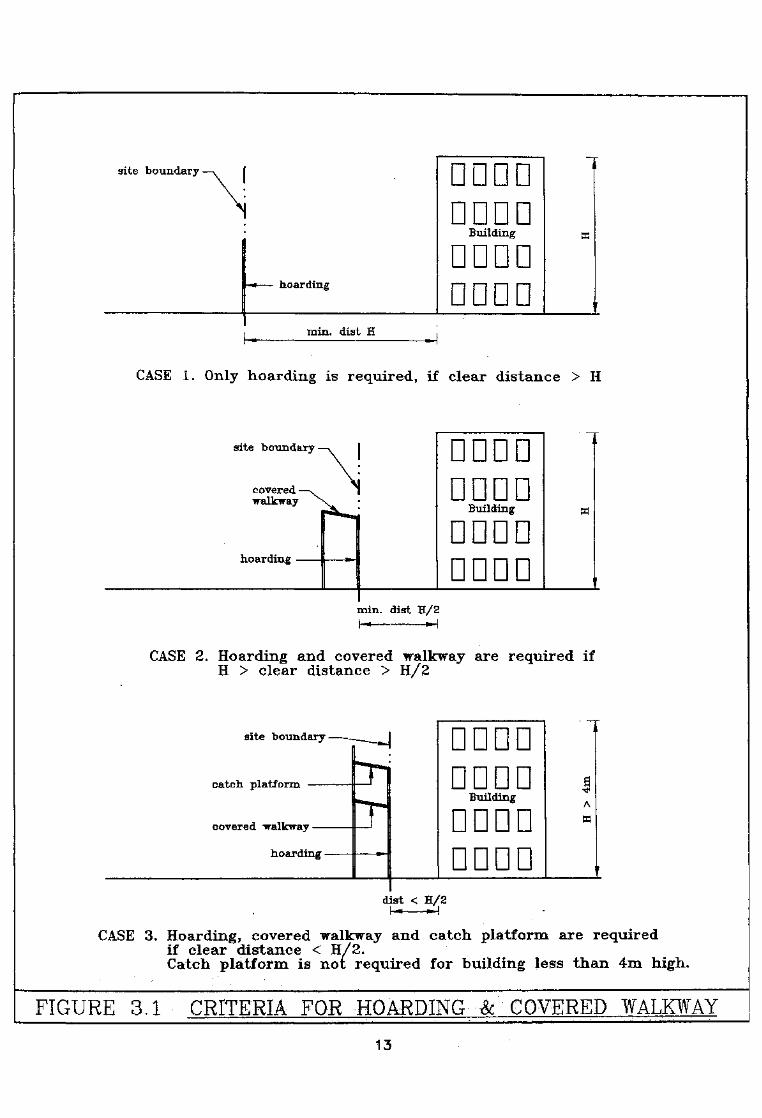
The primary purpose of hoarding and covered walkway is to provide protectionof the public during the construction or demolition of buildings. Generally,hoarding isolates the demolition site from the public, thus preventingunauthorized access and trespassing. The covered walkway, in conjunctionwith catch platform, provides additional protection to the pedestrian trafficagainst falling debris. Suggested designs for hoarding, covered walkway andcatch platform are listed in the following:
3.2.1 Requirements for Hoarding, Covered Walkway and CatchPlatform
The criteria for use of covered walkway for a site depend on the heightof the building being demolished and its proximity to the vehicularand/or pedestrian traffic. The requirements for hoarding, coveredwalkway and catch platform are described in the following:
(A) For buildings that have a clear space between the building line andthe lot boundary equal to or more than the building height(hereinafter referred to as clear space), only hoarding shall berequired;
(B) Covered walkway shall be provided for building with clear spaceless than the building height;
(C) Covered walkway with catch platform shall be provided forbuildings with clear space less than half the building height. Nocatch platform is required for building less than 4 m high;
(D) The hoarding and/or covered walkway shall be provided along thefoil length of the site boundary adjacent to public access. Thewidth of the catch platform shall not be less than 2 m when it abutsa street;
(E) The requirements for hoarding, covered walkway and catchplatform are illustrated in Figure 3.1.
12
site boundary — \
N.
-* — hoarding
D D D DD D D D
Building
D D D DD D D D
'
ffl
min. dist H
CASE 1. Only hoarding is required, if clear distance > H
site boundary — v
covered — walkway ^
ND D D DD D D D
Building
D D D DD D D D
tt
min. diat H/2
CASE 2. Hoarding and covered walkway are required ifH > clear distance > H/2
site boundary — -~~,
covered wstlfewEiv ' ' ^
lioo.i'cl.ins' • ••
— iT|T
i D D D DD D D D
Building
D D D DD D D D
j
5*#
A
n
dist < H/2h-—^H
CASE 3. Hoarding, covered walkway and catch platform are requiredif clear distance < H/2*Catch platform is not required for building less than 4m high.
FIGURE 3.1 CRITERIA FOR HOARDING & COVERED WALKWAY"
13

3,2*2
A minimum vertical clearance of 2.3 m be provided for thecovered walkway. A mmimum clearance of 5.5 m befor the catch platform over a carriageway. 5.5m overgantry shall be maintained as far as practicable. The clearwidths are set out in Table 3.1. The required clear width must not beobstructed in any by sign, temporary supports,scaffoldings or the like.
3.1 of Covered
Existing PavementNo pavement2.5 m or less
over 2.5 m
Clear In Walkwayl . lm1.5 m, if pavement is of insufficientwidth a minimum clear width of l.lmshall be maintained2m
3.2.3 Design Criteria
The roof of the covered walkway shall be designed to support aunifomily distributed load of 7,5 kPa. The combined covered walkwayand catch platform structure shall be designed to sustain a uniformlydistributed load of 7.5 kPa or a point load of 45 kN acting on aneffective area of 300 mm x 300 mm. Design criteria for coveredwalkway and catch platform are summarised in Table 3.2. Thehoarding, covered walkway and catch platform shall be designed tosustain the wind load according to the current Code of Practice on WindEffects in Hong Kong or its latest equivalent publication. The locationof the proposed covered walkway shall be compatible to the existingtraffic environment
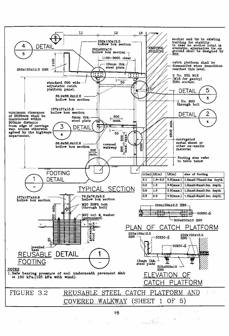
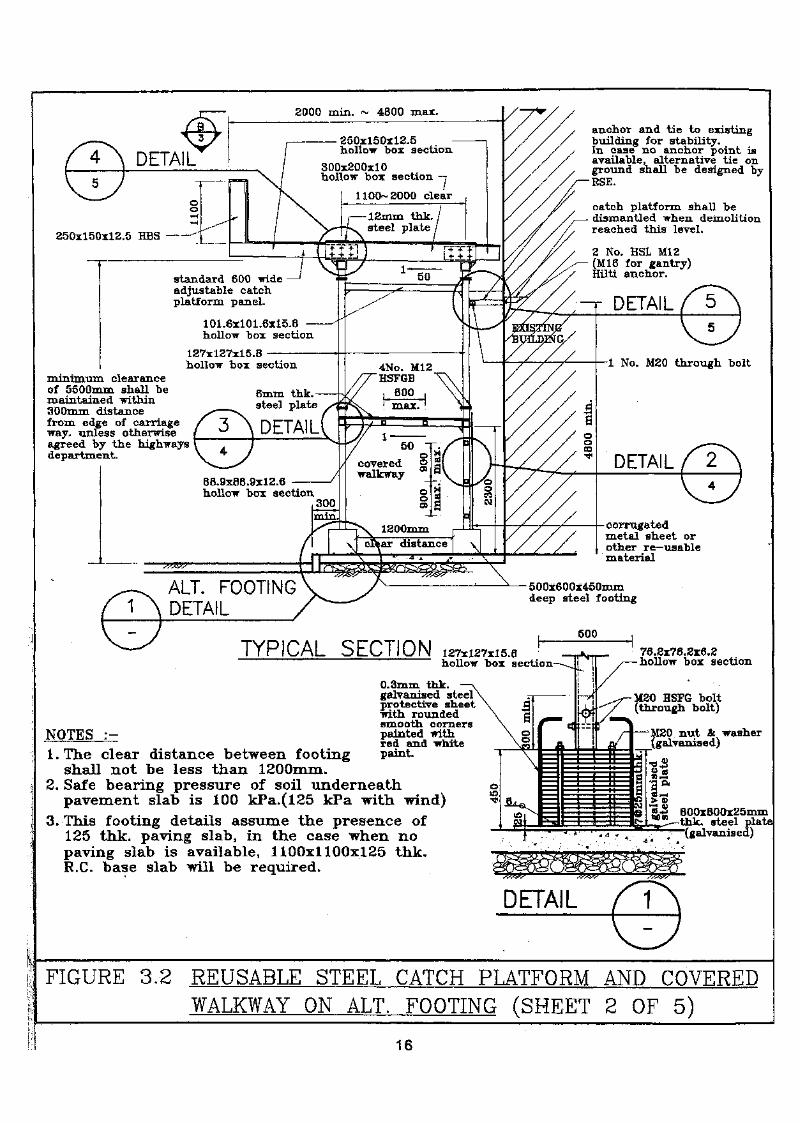
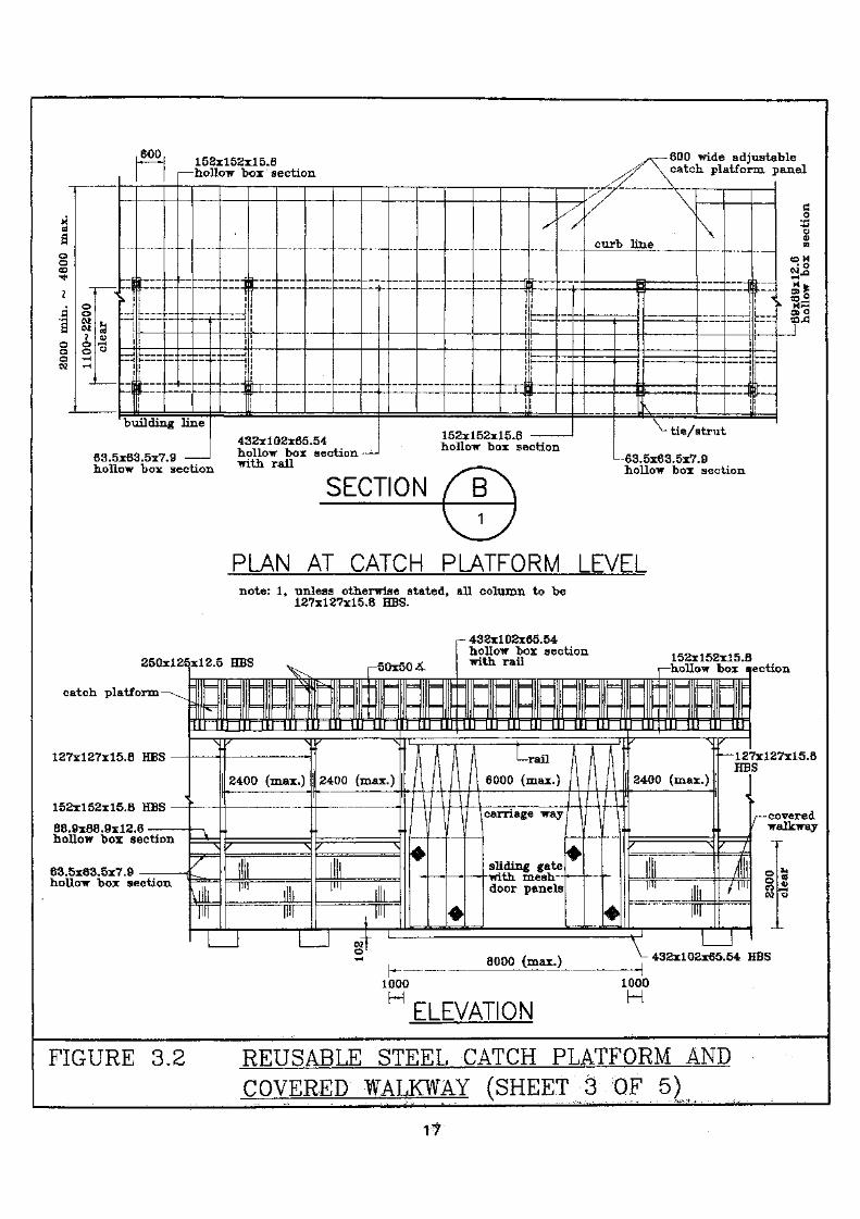
Typical details for the catch platform and covered walkway areillustrated in Figure 3.2
Table 3.2 Design Criteria for Covered Walkway and Catch Platform
CoveredWalkwayCatch Platformand CoveredWalkway
UniformDistributed Load
7.5 kPa
7.5 kPa
Point Load
-
OR 45 kN distributed overan effective area of 300 mmx 300 mm.
14
250x150x12.5hollow box section
300x200x10hollow bos section
1100-2000 clear
12mm tnk.steel plate250x150x12.5 HBS -
standard 600 wideadjustable catchplatform panel.
88.9x88.9x12.6hollow box section
88.9x88.9x12.6hollow box section covered
walkway
anchor and tie to existingbuilding for stability.In case no anchor point isavailable, alternative tie onground shall be designed by
<— RSE.
catch platform shall bedismantled when demolitionreached this level.
2 No. HSL M12(M16 for gantry)Hilti anchor.
DETAIL
127x127x15.8minimum clearance hollow box sectionof 5500mm shall be 6 thkmaintained within ^ " y r*300mm distance — steel plate
from edge of carriageway. unless otherwiseagreed by the highwaysdepartment.
1 No. M20through bolt
DETAIL
corrugatedmetal sheet orother re-usablematerial
Footing size referto table below
FOOTINGDETAIL
TYPICAL SECTION127x127x15.8hollow box section
levelledbase
76.2x76.2x6.2hollow box sectionM20 HSFG bolt(through bolt)
M20 nut &; washer(galvanised)
Ll(m)
2.1
0.9
0.8
0.5
L2(m)
1.3~2.2
1.3
1.5
2.2
L3(m)
0.0(max.)
0,6(naax.)
0.6(max.)
0.5(mas:.)
size of footing
1.6mxQ.75mx0.3m depth
1.2mx0.6mx0.3m depth
1.2mxQ.6mx0.3m depth
1.2xhx0.6mx0.3m depth
250x150x12.5 HBS
-300x200x10 HBS
PLAN OF CATCH PLATFORMr-J <JJrt+>bflcn
250x150x12.5HBS r™50X50 4
250x150x12.5
REUSABLE DETAILFOOTING
NOTES1. Safe bearing pressure of soil underneath, pavement slab
is 100 kPa.(125 kPa with wind).
12mm thk.--^steel plate
300x200x10HBS
ELEVATION OFCATCH PLATFORM
FIGURE 3.2 REUSABLE STEEL CATCH PLATFORM ANDCOVERED WALKWAY (SHEET 1 OF 5)
15
-r DETAIL
250x150x12.5hollow box section
300x200x10hollow box section
12mm ink.steel plate
250x150x12.5 BBS —
standard 600 wideadjustable catchplatform panel.
101.6x101.6x15.8 -hollow box section
127x127x15.8hollow box section 4No. M12
HSFGB800max.
8mm thk.steel plate
88.9x88.9x12.6hollow box section
ALT. FOOTINGDETAIL
5QQx60Qx45Qinmdeep steel footing
anchor and tie to existingbuilding for stability.In case no anchor point isavailable, alternative tie onground shall be designed byRSE.
catch platform shall bedismantled when demolitionreached this level.
2 No. HSL M12(Ml6 for gantry)Hilti anchor.
1 No. M20 through boltminimum clearanceof 5500mm shall bemaintained within300mm distancefrom edge of carriageway. unless otherwiseagreed by the highwaysdepartment. DETAIL
corrugatedmetal sheet orother re—usablematerial
TYPICAL SECTION mtMSJthollow box section
0.3mm thk.galvanised steelprotective sheet•with roundedsmooth corners
NOTES :~ painted withred and white
l.The clear distance between footing paint.shall not be less than 1200mm*
2. Safe bearing pressure of soil underneathpavement slab is 100 kPa.(l25 kPa with wind)
3. This footing details assume the presence of125 thk. paving slab, in the case when nopaving slab is available, 1100x1100x125 thk.R.C. base slab will be required.
76.2x76.2x6.2hollow box section
M20 HSFG bolt(through bolt)
_.JO nut & washergalvanised)
800x800x25mmthk. steel plate'(galvanised)
DETAIL
FIGURE 3.2 REUSABLE STEEL CATCH PLATFORM AND COVEREDWALKWAY ON ALT. FOOTING (SHEET 2 OF 5)
16
600
oo
Io
a)i— <o
63.5
1:d
11
1
^3
|
L
j
1 ,Ii
i1
_.
.—hollow box "section //' \ catch platform i
building line
x63.5x7.9
— _!— 1
1iii(.
iI
j
f
I
432x102x65.54hollow box section —
— j|
I-1 1"*— if
I
152x152x15.8hollow box se
-
j.._ _1
Liir — ~\\iii
"/
ction
curb line
— fiS
a
v
\
*
i:_ Jttt
!1
1!\
~~~J
L „.L _J
riii!
^- tie/strut
SYfia_?hr7.a
>an
«co1c
fc ok j
C
o'i
QD43
hollow box section with rail
SECTIONhollow box section
PLAN AT CATCH PLATFORM LEVELnote: 1, unless otherwise stated, all column to be
127x127x15.8 HBS.
25Qxl2£
r~ 432x102x65.54hollow box sectionwith rail
1*0^1*0^1*015Sx 152x15.8hollow box section
catch platform
hollow box section
63.5x63.5x7,9hollow box section
127x127x15.8HBS
/ — coveredwalkway
h-1000H
8000 (max.) Jf 432x102x65.54 HBS_i1000
ELEVATION
FIGURE 3.2 REUSABLE STEEL CATCH PLATFORM ANDCOVERED WALKWAY (SHEET 3 OF 5)
17

M12THROUGH BOIT
8mm THE.bracket withweld joint
corrugatedmetal sheet
63.5x63.5x7.9y HBS
8mm screw hook@ 300c/c
SECTION
8mm THK. bracketwith bolt joint
corrugatedmetai sheet
63.5x63.5x7.9HBS
fWELD JOINTDESIGN)
8mm THK.bracket —\
fALT BOLTJOINT DESIGNS8ram THK. bracketwith welded joint.
127x127x15.8j—HBS
8 . 75 ,
M12THKQUGH BOLT
127x127x15.8HBS
63.5x63.5x7.9HBS
ALT. WELD JOINTOF BRACKET
SECTION
-8mm screw hook@ 300c/c
BOLT JOINTOF BRACKET
ALT. WELD JOINTOF BRACKET
SECTION
8mm THK.bracket
-M2QTHROUGH BOLT
BOLT JOINTOF BRACKET
"127x127x15.8HBS
4 No. Ml 6throngh bolt
8mm THK.bracket
4.No. M12HSFGB
88.9x88.9x12.6HBS
185x185x20mmTHK. steel plate.
4 "No. M12~/HSFGB
SECTION
88.9x68.9x12.6HBS
10mm THK.stiffener
FIGURE 3.2 REUSABLE STEEL CATCH PLATFORM ANDCOVERED WALKWAY (SHEET 4 OF 5)
18
, -4No. M16/ through bolt
12mm THK.steel plate
6No. M36through bolt
300x200x10 HBS
^ ......... - 152x152x15.8 HBS
—Ml 6 through bolt
88.9x88.9x12.6HBS
lOxnm THK.stiffener
152x152x15.82$.-
IQinm THK.stiffener
-152x152x15.8 HBS
-4No. M16HSFGB
270xl70x20mm THK.steel plate
152x152x15.84-
INo. M20/-through bolt
suitable sleeper platesto be provided.
— 152x152x15.8HBS
-200x800x10 plate
SECTION
2No. M16through bolt
88:9x88.9x12.6HBS
--lNo. M20through bolt
4No. HSL M12anchor boltor other approvedequivalent
DETAIL
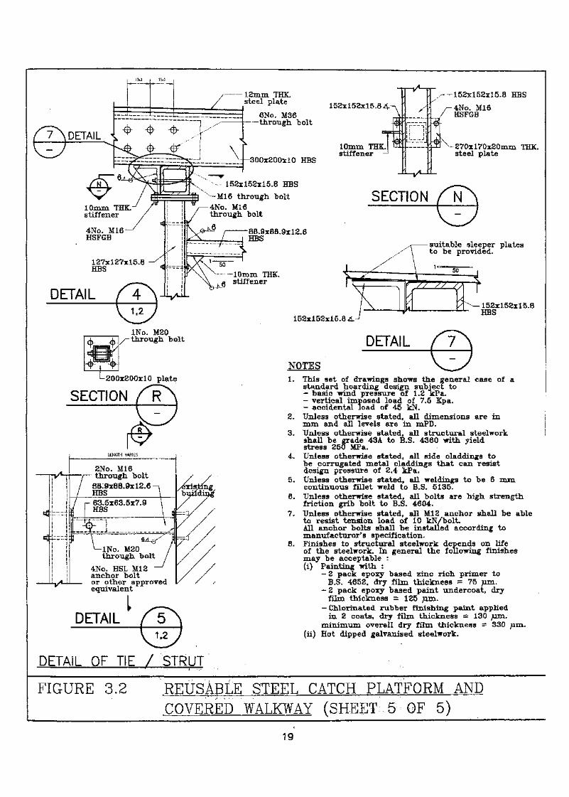
NOTES1. This set of drawings shows the general case of a
standard hoarding design subject to- basic wind pressure of 1.2 "kPa.- vertical imposed load of 7.5 Kpa.- accidental load of 45 kN.
2. Unless otherwise stated, all dimensions are inmm and all levels are in mPD.
3. Unless otherwise stated, all structural steelworkshall be grade 43A to B.S. 4360 with yieldstress 250 MPa.
4. Unless otherwise stated, all side claddings tobe corrugated metal claddings that can resistdesign pressure of 2.4 kPa.
5. Unless otherwise stated, all weldings to be 6 mmcontinuous fillet weld to B.S. 5135.
6. Unless otherwise stated, all bolts are high strengthfriction grib bolt to B.S. 4604.
7. Unless otherwise stated, all M12, anchor shall be ableto resist tension load of 10 kN/bolt.All anchor bolts shall be installed according tomanufacturer's specification.
8. Finishes to structural steelwork depends on lifeof the steelwork. In general the following finishesmay be acceptable :(i) Painting with ;
— 2 pack epoxy based zinc rich primer toB.S, 4652, dry film thickness = 75 nm.
.- Z pack epoxy based paint undercoat, dryfilm thickness = 125 nm.
- Chlorinated rubber finishing paint appliedin 2 coats, dry film thickness = 130 m.
minimum overall dry film thickness = 330(ii) Hot dipped galvanised steelwork.
DETAIL OF TIE / STRUT
FIGURE 3.2 REUSABLE STEEL CATCH PLATFORM ANDCOVERED WALKWAY (SHEET 5 OF 5)
19
3.2.4 Proper Use of Covered Walkway
Debris shall not be accumulated on the roof of the covered walkway. Itshall not be used for any other purposes such as displayingadvertisement or for storage of building materials and equipment insideor above the covered walkway.
If it is intended to build a temporary contractor's shed over the coveredwalkway, it must be structurally independent of the covered walkway.The roof of the contractor's shed shall sustain the design load criteriafor the catch platform or covered walkway whichever is applicable.
The roof of the covered walkway shall be pitched inwards to bettercontain the debris and for roof drainage. Upstand edge board of 1.1 mor higher measured from the toe of roof line of the catch platform *souter edge shall be provided to retain the fallen debris.
3.2.5 Construction
As far as practicable, the structural components of the covered walkwayand catch platform shall be prefabricated and fastened together on siteby bolts so that they can be reused. Site welding shall be minimised inorder to reduce the erecting time and potential hazard to pedestrians orvehicular traffic. Prefabricated shoring systems, glass fibre reinforcedpanels and other ready to use systems shall be used for the hoarding,cover walkway or catch platform installation as much as possible.
3.2.6 Lighting
A system of temporary lighting shall be provided for the coveredwalkway and shall be maintained in good order. The averageilluminance on the floor level of the covered walkway shall be withinthe range of 35 lux to 50 lux. The lighting shall be weather-proofed.A recommended lighting layout for typical covered walkway is theinstallation of luminaries complete with 18 W or 20 W 600 mm longtubular florescent lamps at 3 m spacing,
3.3 Scaffoldings and Screen Covers
3.3.1 Scaffoldings
Bamboo scaffolds or metal scaffolds shall be used for top downdemolition projects. Both bamboo scaffolds and metal scaffolds areconsidered acceptable provided that they are erected according to theContraction Sites (Safety) Regulations and the Code of Practice forScaffolding Safety.
20
(A) Scaffolding Construction and Work Platform Requirements
The erection, dismantling and safety requirements of the workplatforms and scaffold shall be in accordance with theConstruction Sites (Safety) Regulations and the Code of Practicefor Scaffolding Safety (CoPSS). The erection and dismantling ofthe scaffold shall be carried out by'Competent workers possessingadequate experience of such work, under the immediatesupervision of a competent person. Djaifelejow scaffoldings shallbe provided for all demolition projects by top down methods.Work platforms shall be provided on the three consecutive liftsdirectly below the floor being demolished. Toe boards shall beprovided at the outer edge. These platforms may be used as workplatforms and also for precautionary measures to retain smalldebris falling out of the building. Periodic maintenance shall beperformed to remove any debris accumulated on the platforms.
(B) Bamboo Scaffold
Structural ties to the building structure shall be provided. Bambooscaffold shall be tied to sound anchors at intervals of not more than4m in both horizontal and vertical directions.
If the scaffold is higher than 15m, steel brackets anchored to theexisting building structure or other support system shall beprovided at interval of not more than 15m to support the scaffold.The steel brackets and anchors or other equivalent support systemshall be designed by a Registered Structural Engineer to properlysupport the weight of the scaffold and the loading including thecatchfans, work platforms, etc.
(C) Metal Scaffold
As a minimum, the scaffold shall be able to support the live loadimposed on three consecutive layers of work platform plus its ownweight. Additional loading conditions, if any, shall be included indetenniniiig the allowable height for the scaffoldings. Tie toexisting structure shall be in accordance with manufacturer'srecommendations.
21
(D) Dismantlkg
Dismantling of the scaffolds coincide with the demolitionprogress. When the wall ties are disconnected due to thedemolition of the building structure, the unsecured section of thescaffolds shall be removed accordingly. The unbraced sectionsshall not be higher 2m from the nearest anchor.
3.3.2 Screen Covers
(A) Requirements
Two layers of protective screen shall be placed over the scaffoldsto completely enclose the building structure for retaining dust andsmall debris. Tarpaulin and heavy duty nets shall be used to coverthe exterior face of the scaffold. Tarpaulin shall be placed over thenet. The screen system shall satisfy the requirements under the AirPollution ControJ^Construction Dust) Regulation administered bythe Environmental Protection Department, where applicable.
(B) Ties
The protective screens shall be secured to the scaffoldings at notless-than 2 m intervals at both horizontal and vertical directions orthe width of the net, whichever is less. The screens shall have anunimum overlapping width of 3 00 mm.
(C) Nets
(1) Materials and Installation
Heavy duty nets shall be relatively light weight and havegood retaining capability for small debris. The materialshall resist ultra-violet light deterioration. The nets shall besecured to the scaffold and at the catchfan so that debris canbe retained and not deflected onto the ground.
The net shall meet the minimum requirements as listed inTable 3.3 or approved equivalent
22
33 for Net
Criteriamaterialstring diameterplysmesh grid openingweight
polyethylene11620mm130 g/m2
(D) Tarpaiilin
Tarpaulin shall be light weight and constructed of fire retardantmaterials.
The fire retardant characteristic of the tarpaulin shall meet eitherone of the following requirements:
(1) Class B material as specified in British Standard 5867;
(2) Flame retardant test for certain items, light weight clothsmethods, provided by the Fire Retardant Regulations forProtective Canvas for Construction, Japan MinisterialOrdinance of the Ministry of Home Affair;
(3) Any equivalent standard criteria or testing.
3.4 Catcfafatt
3.4.1 •Requirements
The design intention of the catchfans is to catch small pieces of buildingdebris that passes through the protective screen and net, and thecatchfans are not designed to collect large pieces of building debriswhich should have been collected by the protective screen or net Asmall piece of debris could be disastrous after gaining enough kineticenergy through falling great heights. Thus, a catchfan shall be installedat a vertical distance of not more than 10 m below the working floor. Acatchfan shall have a horizontal extension of 1.5 m from the exteriorface of the scaffolding. The typical angle of inclination shall be 20° to45° from the horizontal plane. Catchfans shall be'used only asprecautionary measures and shall not be used as temporary support forany anticipated loads.
23
Both bamboo catchfans and metal catchfans are acceptable providedthat they are properly installed. Under the present craftsman'stechniques, bamboo catchfans can be applied to either bambooscaffolds or metal scaffolds, but metal catchfans are allowed to bemounted on metal scaffolds only.
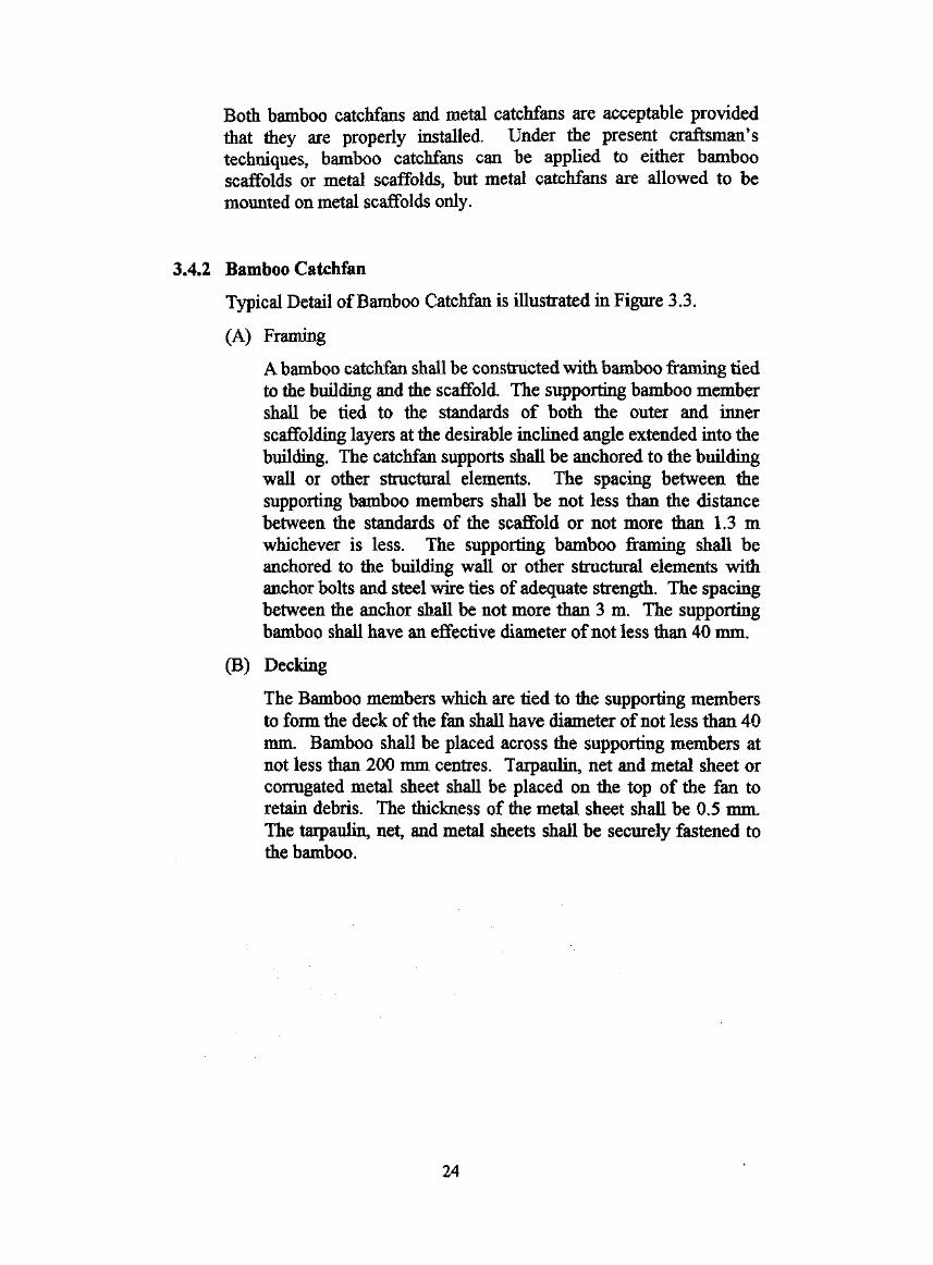
3 A2 Bamboo Catehfan
Typical Detail of Bamboo Catchfan is illustrated in Figure 3.3.
(A) Framing
A bamboo catchfan shall be constructed with bamboo framing tiedto the building and the scaffold. The supporting bamboo membershall be tied to the standards of both the outer and innerscaffolding layers at the desirable inclined angle extended into thebuilding. The catchfan supports shall be anchored to the buildingwall or other structural elements. The spacing between thesupporting bamboo members shall be not less than the distancebetween the standards of the scaffold or not more than 1.3 mwhichever is less. The supporting bamboo framing shall beanchored to the building wall or other structural elements withanchor bolts and steel wire ties of adequate strength. The spacingbetween the anchor shall be not more than 3 m. The supportingbamboo shall have an effective diameter of not less than 40 mm.
(B) Decking
The Bamboo members which are tied to the supporting membersto form the deck of the fan shall have diameter of not less than 40mm. Bamboo shall be placed across the supporting members atnot less than 200 mm centres. Tarpaulin,, net and metal sheet orcorrugated metal sheet shall be placed on the top of the fan toretain debris. The thickness of the metal sheet shall be 0.5 mm.The tarpaulin, net, and metal sheets shall be securely fastened tothe bamboo.
24
screen tie at -every 2mhorizontallyand verticallyover lappingwidth not lessthan 300mm
tarpaulin
net
screen tie at catchfan
wall tie
steel wires with anchor boltmaximum spacing 3m
WINDOW OR WALLOPENINGS
0.5mm /metal sheet-
net
tarpaulin
bamboo with —effective diameternot less than40mm
bamboo maximumspacing 200mmcentres
steel wires with anchor boltmaximum spacing 3m at wallwithout opening
steel wires with anchor boltmaximum spacing 3m atwindows or wall opening
-wall tie
I _ 1.5m(minimum) 1. Bamboo for the construction of scaffold, and catchfan
shall have an effective diameter not less that 40mm.2. Metal sheet, net and tarpaulin shall be fastened
to the bamboo deck at 4 corners of the sheet or atspacing no less that 1.5m apart whichever is less.
FIGURE 3.3 TYPICAL DETAIL FOR BAMBOO CATCHFAN ANDSCREEN COVER
The steel catchfans are considered as temporary cantilevered structureswith steel framing extended from the building. The use of expansiveanchor bolts in erecting the catchfan shall be avoided as far aspracticable since the anchor bolt may be loosened by vibration
the demolition process. In the case when anchors areused, they shall be applied cautiously with extreme care; and not as aprimary support. Extreme care shall be exercised in erecting and
the catchfan to avoid the structural components fromaccidentally off. All the components of the steel catchfan shallbe supported, and securely fastened to the lifting appliances orsupporting structural element until the installation is completed.Catchfan may be constructed with components of prefabricatedsteel/metal scaffold. Such use is particularly compatible with metalscaffolds. The design and installation of catchfan using prefabricatedmetal scaffold components shall be in accordance with themanufacturer's recommended criteria. As far as practicable, thecomponents of the catchfan shall be prefabricated and fastened by boltto minimise welding.
3.5
3.5.1 General
(A) Requirements
Temporary supports to the structure or the elements of thestructure being demolished shall be provided for any orcombination of the following conditions:
(1) when the whole or any part of the structure is subjected toexcess loading derived from the demolition activities,movement of powered mechanical plants or debrisaccumulation;
(2) when any part of the structure or any element beingdemolished is not self-supporting; or
(3) when the temporary stability of the structure or its elementscould be impaired as a result of the demolition activities.
Temporary supports shall not be removed until its supporting loadsare completely removed.
26

On the other hand, temporary supports be removed as muchas possible and practicable after demolition. In the case whentemporary supports have to remain, the Owner, his AuthorizedPerson, Registered Structural Engineer and Registered SpecialistDemolition Contractor shall be responsible for routine inspectionand maintenance of such temporary works until they arecompletely removed.
(B) Cantilever Structures
Temporary supports shall be required during the demolition ofcantilever construction that may affect the safety of the public. Ifthe anchorage or holding down load of the cantilever constructionhas been removed prior to the demolition of such elements, thecantilever must be temporarily supported before the removal ofthe anchorage and holding down load. The area underneath anycantilever structure shall be protected by a temporary platformwhich is designed to resist the anticipated demolition loading priorto in-situ demolition of any cantilever structures, unless thecantilever structure is demolished by cut and lift, or other similartechniques.
(C) Catch Platform
Catch platform shall be provided on top of the covered walkway inaccordance with the requirements and design criteria as describedin 3.2.
Catch platform shall also be provided underneath structuralelements when the area adjacent to or directly underneath the saidstructural element requires protection from falling debris or otherpotential hazard caused by the demolition. These structuralelements generally include, but are not limited to, projectedcanopies and balconies. Depending on the demolition process,catch platforms may be required underneath special structures suchas external architectural features and prestressed concreteelements. Catch platform shall be installed prior tocommencement of demolition. Catch platform shall be designed tosupport the anticipated loading condition during the demolitionprocess.
(D) Adjacent Building
27
Temporary supports shall be provided to adjacent propertiesincluding, but not limited to, buildings, public or private utilities,slopes, retaining walls or land when the removal of the building orany part of the building being demolished could affect the stabilityof such properties. Common features, such as truncatedcontinuous beams, exposed party walls and common staircases,shall be protected and stabilised.
Safe ingress and egress for adjoining properties shall bemaintained. Adequate supports shall be provided to maintain thestability of common staircases for maintaining continuous accessfor the adjoining properties. Demolition project, such as thetenement house, may involve the removal of structural membersthat are part of the integral structure for supporting the remainingbuilding. Appropriate supports to brace the structure shall beinstalled.
(E) Incomplete Demolition Projects
When a demolition project is shut down for a prolonged periodbefore its completion, the remaining structure, if any, shall bestabilised by temporary support and/or bracing systems.
3.5.2 Materials and Types
(A) Materials
The temporary supports used for demolition shall be built withstructural steel, heavy timber, fill embankment/buttress, or othermaterial which is considered to be appropriate for the purpose.
(B) Pre-manufactured System
Pre-manufactured components such as tubular shores, telescopesteel props, framed towers, etc., may be used as temporarysupports provided their design capacity and their erection andmaintenance requirements are followed in strict accordance withmanufacturer's recommendations. Where the design capacity of apre-manufactoed component cannot be established by standardstructural design and analysis, tests shall be performed to establishthe design capacity.
(C) Extsiag Structure
Existing non-structural concrete or partition walls shall not beconsidered as part of the temporary support system unless it isshown by structural analysis that they are adequate for thepurpose.
28

(D) Used Timber
Timber which has been damaged or has deteriorated due torepeated use, insect, decay or chemical attack shall not be used.
(E) Used Structural Steel
Used structural steel shall not be employed unless pre-approved bythe Registered Structural Engineer. Where used structural steel isemployed, the actual dimensions of the steel section shall bemeasured and its section properties shall be calculated on the basisof the least cross-sectional area including appropriate allowancesfor any existing bolt holes, etc. Where the material sources are notknown, material properties shall be checked.
All used structural steel with excessive pre-existing bolt holesshall be repaired. Steelworks that has been repaired by weldingmay be used provided that the remedial work has been carried outaccording to the Code of Practice on Structural Use of Steel(1987).
3.5.3 Loads
(A) Gravity Loads
The temporary support systems shall be designed tosimultaneously withstand, all of the following loads:
(1) construction loads such as the construction operatives, handtools and small equipment;
(2) debris accumulation and impact from fallen debris;
(3) heavy machinery used.
Subject to a detailed evaluation for special circumstances, in nocase shall the construction loads due to item (1) be assumed to beless than 1.5 kPa.
Loading due to items (2) and (3) shall be established by the actualweight of the debris likely to be accumulated and the weight ofmachinery to be used. In the case where no working load isavailable, minimum impact factor of 1.25 shall be applied to thestatic weight of the machinery for the purpose of design for thetemporary works to account for the vibration from movingequipment on a suspended floor.
(B) Lateral Loads
29

To ensure the they shallbe designed to the
(1) The wind force be in withSection 3.4 of the Code of on inHong Kong (1983). is not exposedto wind and its is withits own thisrequirement may be waived;
(2) A of 3% of vertical at the centre ofgravity of these applied loads, or a of 1.5 kN permetre length of the whichever isgreater;
(3) Any calculated or reasonably forceswhich shall be applied to the temporary due toadjacent slope/retaining wall or building, movingmachinery or impact from of debris.
(C) Design Consideration for Temporary Support
(1) All temporary support systems shall be supported onadequate foundations or floors. In the case when theimmediate floor below the floor under demolition is notadequate to carry the imposed loading from the demolitionactivities, shoring shall be carried down to the lower floorsuntil adequate support is achieved;
(2) The lower floors may be allowed to carry the balance of theexcess loading provided that their support capacities are notexceeded. The shores on the lower floors shall be alignedin the same position on each floor to provide continuoussupport without causing punching shear or reverse bendingin the lower floors;
(3) Attention shall be paid to avoid placing the temporarysupports on foundations which may exhibit intolerabledifferential settlements;
(4) The load capacity of the floor slabs shall be checked toensure that they can adequately resist the concentratedloads from the temporary supports. Distributing the loadsthrough the use of sleepers and base plates may increase thecapacity of the floor slab.
30

3.5,4
The capacity of the support system and its components shall bedetermined by using the codes as listed in Appendix D. Other wellestablished codes may be used as supplement whenever applicable.
3»5e5 Temporary Propping
Prefabricated propping system may be used to support the operation ofthe mechanical plant, or other loading during the demolition process ona suspended floor. A guideline for propping requirements undertypical loading conditions is depicted in Table 3.4.
Table 3.4 Propping Requirements on the Operation ofMechanical Plant on Suspension Floor
Design imposed loadof floor to bedemolishedMaximum weight ofmechanical plantallowedMinimum no. ofconsecutive floorsrequired to distributemechanical plantloading, throughproppingMinimum no. ofconsecutive floorsrequired to distributelocalised loading fromtemporary ramp,through proppingMaximum spacing ofsteel props in eachdirection
3kPa
11,600kg
5
5
1.2m
5kPa
11, 600 kg
3
4
1.2m
7.5 kPa
11,600kg
2
3
1.2m
12.5 kPa
11,600kg
2
2
1.2m
The application of the propping requirements in Table 3.4 shall followthe limitations and design requirements as listed below:
(A) The propping requirements are not applicable to special structuresand unconventional layout as described in 2.1.3(A)(3);
31
(B) In general, debris accumulation shall not be permitted unless thedebris accumulation is justified by engineering calculation;
(C) The propping design is based on the use of structural steel accessramp. The gradient of the ramp shall not be steeper 30°;
(D) Minimum bearing capacity for the steel prop shall not be less than25 kN for supporting the mechanical plant and 45 kN for areaunder the access ramp;
(E) The props shall be braced to provide lateral restraints in at least 2directions;
(F) The top and bottom supports of props shall be adequately securedand wedged tight;
(G) Adequate spreader shall be provided for props bearing on ground,if necessary, to avoid undue settlement.
3.5.6 Erection and Dismantling
(A) All temporary supports shall be erected strictly in accordance withthe approved plans and/or in accordance with the manufacturer'srecommendations. All pre-manufactuied systems and theiraccessories shall be examined for structural defects. Any damagedcomponents and their accessories shall be discarded;
(B) All vertical supports shall be erected and maintained plumb asmuch as possible. Other arrangements may be acceptable as longas the supporting structural members are not stressed beyond theacceptable limits;
(C) All bracing shall be installed in accordance with the approvedplans and the manufacturer recommendations. Its connectionsto the main members shall be checked to ensure tight fit andadequacy;
(D) All temporary supports shall not be dismantled or modified untiltheir use is no longer required. The design of the temporarysupports shall ensure that they can be dismantled safely withoutimposing danger to the workers or the public.
32

3*6 of
3*6*1 General
Stability treatment shall be provided to protect elements thatmay be affected by the demolition project. The design of the bracingsystem shall be based on a structural assessment engineeringevaluation to provide necessary and sufficient protection for theaffected properties.
3.6.2 Party Walls and External Walls
Party walls that separate the adjoining building and the demolitionproject shall remain and be protected during and after the demolitionproject. Redundant party wall shall be removed as far as possible.Demolition of structural elements adjacent to the party wall or theexternal wall of adjoining building (hereinafter in section 3.6.2 referredto as external wall) shall be performed by manual method with extremecare to prevent any damage to the party wall or the external wall.
The party wall or external wall stabilisation and treatment shall beapplied on each floor immediately after the said floor is demolished,
(A) Waterproofing
The party wall or external wall shall be protected againstinfiltration and water seepage when it is exposed to the weather.Roof lines and wall joints are more susceptible to water leakageproblems and shall be checked for waterproofing treatment. Allloose bricks or fill materials shall be removed. All openings andvoids shall be filled with concrete.
(1) Waterproofing may be achieved by cement mortartreatments. The application of the cement-mortar finishshall follow the procedures below:
(a) The surface of the party wall or external wall shallbe thoroughly cleaned;
(b) Application of bonding agent in accordance withmanufacturer's recommendation;
(c) Cement exterior finishing shall be applied in twocoats:
33
(I) The first coat a thicknessof 10 mm with a cement-lime-sand mix ratioof 1:2:6;
(li) The second coat shall have a minimumthickness of 10 with a ceraent-lime-sandmix ratio of 1:3:6.
(2) Waterproofing paper may be used as temporary treatment toprotect the party wall or external wall The waterproofingpaper on the upper row shall always overlap the row of paperimmediately below. The waterproofing paper shall besecurely fastened to the building wall.
(3) Waterproofing to party wall or external wall shall be carriedout as soon as practicable. In general, such water proofingwork shall be performed as building demolition progresses.
(B) Structural Supports
The exposed party walls or unprotected external wall may betemporarily supported by timber raking shores or installation ofstiffeners consisting of structural steel members with concretecover or other corrosion protective system as designed by theRegistered Structural Engineer. If structural conditions allow, thestability of the party wall or the external wall may be improved byleaving a portion of the common beams and slabs which areconnected to the party wall.
The layout of the temporary supports to the party wall or theexternal wall shall be considered in the new construction.Permanent support is required to ensure continuity of the partywall support and minimise any possible interference. Thetemporary wall treatment shall be maintained until the applicationof the permanent treatment which may be incorporated in theconstruction of the new building.
3.6.3 Foundation Support
A thorough evaluation shall be conducted for demolition involvingbasement, below ground structures or any structure that may affect thefoundation of the adjoining properties. Appropriate shoring,underpinning 6r other protective measures shall be installed ifnecessary. Details of the demolition of the underground structure shallbe referred to in 5.9.
34
3.7
3.7.1
Any closure of roads and walkways may seriously impact thetraffic/pedestrian circulation and cause disruption to the public.Therefore, as far as practicable, the installation of the precautionarymeasures and the demolition operation which causes any closure oftraffic lanes shall be avoided. If unavoidable, priorpermission/arrangement of Police and Transport Departments shall beobtained. Temporary closure of a traffic lane may be considered fornight work. Temporary closure of a traffic lane may also be consideredfor exceptional cases where there is no other practical alternatives tosafely demolish the building elements such as projected canopies,balconies or verandah.
3.7.2 Traffic Assessment
If traffic closure is necessary, a proper Traffic Impact Assessment shallbe submitted to the Transport Department and the Police for theirreview and approval. The Traffic Impact Assessment shall conform tothe requirements of the Transport Department.
3.7.3 Site Access :
Safety measures for construction access to and from the site shall beconsidered in a demolition project. Proper sightline, segregation,loading/unloading location, illumination etc. shall be provided for theprotection of vehicular and pedestrian traffic from the ingress andegress of construction vehicles.
3.8 Special Safety Considerations
3.8.1 Training and Communication'
Demolition workers, including plant operators, shall go through properjob safety training and be informed of the potential hazards by attendingtraining sessions as well as on-the-job training. At present, theConstruction Industry Training Authority has organised the followingtraining courses :
(A) Demolition of Building Courses for Supervisors/Foremen,(B) Demolition of Building Courses for Plant Operators.
35
Site safety and project understanding shall be promoted through aninduction meeting at the beginning of the project, where informationrelated to the project such as the proposed method and procedures,potential danger during the operation, safety measures and projectspecifics can be disseminated to all on site personnel.
The safety concept can be maintained by regular safety meetingsthroughout the projectperiod. Sitesafety attitude maybe cultivated bystrict enforcement of the safety regulations by the site supervisor.
Apart from instilling the importance of safe attitudes to workers andplant operators, they shall be trained by competent instructors on thefollowing to observe safety precautions in accordance with regulationsas listed in Appendix D where appropriate:
(A) Working at Heights;
(B) Working in Confined Spaces;
(C) Working with Lifting Appliances and Lifting Gears;
(D) Use of Personal Protective Equipment;
(E) Hot Works;
(F) Handling of Chemicals;
(G) Health Hazards in Demolition Works;
(H) Safe plant operating zones and safe plant manipulation zones.
3.8.2 Equipment Maintenance
All equipment shall be tested and examined before use. They shall beproperly stored and maintained. The equipment shall be inspected dailyand results of the inspection shall be recorded accordingly. A detailedsafety instruction shall be provided to cater for specific situations of theproject, if necessary.
3.8.3 Electrical Safety
A properly connected power source from a local electric utility supplieror a mobile electricity generator shall be utilised in demolition sites. Thesafety requirements given in the Factories and Industrial Undertakings(Electricity) Regulations shall be adhered to.
36

3.8.4 Fire
All flammable goods shall be removed from site unless they arenecessary for the works involved. Any remaining flammable goodsshall be stored in proper storage facilities. All furniture,, timber, doors,etc. shall be removed before any welding work is performed. Firefighting appliances shall be provided and maintained in workingconditions.
The Construction Site (Safety) Regulations require the contractor tomaintain in good condition and free from defects all fire fightingappliances provided in such construction site.
Details of emergency access are further discussed in 3.8.6.
3.8.5 Occupational Health
The health of workers on site shall be properly protected in accordancewith the relevant subsidiary regulations of the Factories and IndustrialUndertakings Ordinance and the Occupational Safety and HealthOrdinance with particular attention to the following areas:
(A) Exposure to Dust;
(B) Chemical Exposure;
(C) Heat Stress and Ventilation;
(D) Noise Exposure;
(E) Medical and First Aid Facilities;
(F) Sanitation;
(G) Occupational Diseases.
3.8.6 Emergency Exit Requirements in Demolition Sites
Emergency exits shall be provided during building demolition. In caseof any emergency evacuations, the emergency exit will serve as alifeline for transportation of injured workers. A minimum of one exitroute shall be maintained and designated as the emergency exit at alltimes during the demolition. Adequate lighting and fire extinguishingequipment shall be provided. Emergency exit shall be properlyprotected, free of obstruction, and properly marked with exit signs orother indications to clearly show the route. All workers shall beinformed about the exit route.
37
3.8.7
Demolition work will cause vibration to neighbouring buildings orstructures to various extent, depending on the of demolition.The most serious vibration is caused by implosion. The effect ofvibration caused by implosion are categorised as follows :-
L permanent ground distortion produced by blast-induced gaspressures,
2. vibratory settlement of foundation materials,
3. projectile impact (i.e. blast fly rock),
4. vibratory cracking from ground vibration or air blast.
These effects will have to be dealt with specifically in the methodstatement for implosion. For other mechanical demolition methods, thevibration effect is usually less than some other construction processes,such as percussive piling and blasting. In some cases, the trafficvibration caused by heavy duty tractors are more significant than thatcaused by mechanical demolition. In order to identify the actual causeand effect of vibration, Registered Specialist Demolition Contractors areadvised to carry out vibration monitoring during demolition. As ageneral guideline, the peak particle velocities at any adjoining structureshall not exceed 15mm/sec for prolonged vibration caused bymechanical demolition.
3.9 Environmental Precautions
The general requirements to minimise environmental impacts fromconstruction sites can also be applied to demolition processes. The followingsections contain some of the procedures to be adopted:
3.9.1 Air Pollution
Concrete breaking, handling of debris and hauling process are mainsources of dust from building demolition. Dust mitigation measurescomplying with the Air Pollution Control (Construction Dust)Regulation shall be adopted to minimise dust emissions. Burning ofwaste shall not be allowed. Diesel fumes generated by mechanical plantor equipment shall also be controlled.
38
Noise pollution arising from the demolition works including, but notlimited to, the use of specified powered mechanical equipment (SPME),powered mechanical equipment (PME), such as pneumatic breakers,excavators and generators, etc., scaffolding, erection of temporaryworks, loading and transportation of debris, etc. affects the workers, andthe sensitive receivers in the vicinity of the demolition site. SileritypePME shall be used to reduce noise impact-as much as practicable.Demolition activity shall not be performed within the restricted hours asestablished by EPD. Currently under the Noise Control Ordinance,noise from the use of SPME and PME within restricted hours isgoverned by a Construction Noise Permit (CNP) system which isfurther discussed in Appendix E.
3.9.3 Water
The discharge of wastewater from demolition sites requires a validdischarge licence from the EPD and the application of such a licenceshall be made under the Water Pollution Control Ordinance (WPCO).Effluent shall be treated to the standards as stipulated in the licencebefore discharge.
As stated in 3.10.3, the Registered Specialist Demolition Contractorshall maintain proper control of temporary water supply and aneffective temporary drainage system.
3.9.4 Hazardous Materials
If removal of asbestos containing material is needed, an AsbestosInvestigation Report (AIR) shall be submitted to EPD. An AsbestosAbatement Plan (AAP) shall be submitted at least 28 days before theasbestos abatement work commences. The asbestos abatement worksshall be carried out in accordance with the Air Pollution ControlOrdinance (APCO) and the Factories and Industrial Undertaking(Asbestos) Special Regulations before demolition. The procedure fornotification is discussed in Appendix E
Other materials such as LPG cylinders in domestic flats, toxic andcorrosive chemicals for industrial undertakings, and any otherhazardous materials have to be identified and properly handled andremoved prior to the commencement of the demolition of the building.
The management of waste must fully comply with the Waste DisposalOrdinance. Additionally, management of waste which is classifiable asa chemical waste, must also comply with the Waste Disposal (ChemicalWaste) (General) Regulation.
39

3.10 Debris and Waste Handling
3.10.1 Chutes
Debris waste and other materials shall not be thrown, tipped or shotdown from a height where they are liable to cause injury to any personon or near the site.
Existing lift shaft, light well and openings on floor may be used toconvey debris down the building floors. Areas adjacent to the openingsof these features used as a chute shall be barricaded when they are notin use. Warning signs shall be posted to prevent workers from enteringthe area. As an option, plastic chutes may be used inside the flooropenings and lift wells to minimise noise and confine the falling debris.
(A) Lift Shaft
Lift shaft may be used to convey debris inside the building. Theopenings to the elevator shall be adequately enclosed to preventspilling out of debris.
(B) Light Well
All the glass windows in the light well shall be taken out orprotected before using the light well for conveyance of debris inorder to minimise any dangerous situation.
(C) Opening on Floor
Openings on the floor may be used to convey debris. If openingsare created on the floor, the total openings shall be less than 25 %of the total aggregate floor area. Each opening shall not be largerthan 900 mm x 900 mm. Openings shall not cut through structuralsupport elements that may affect the stability of any structuralcomponents.
(D) Exterior Chutes
No demolition materials shall be allowed to fall freely outside thebuilding unless it is confined within a chute. If exterior chutes areused, adequate clear spaces shall be provided for their operation.Temporary refuse chutes, assembled from old metal barrels shallnot be used. The chutes shall not cause any obstruction to thepublic. A dust barrier shall be provided if the chute outlet is nearpublic access. The chute shall be designed and constructed withadequate strength and support to allow safe conveyance of debris.
40
3,10*2
Better site management and practice would not only prevent the mixingof the inert portion together with the non-inert portion of constructionand demolition waste, but could also facilitate and allow on sitesorting, and separation at source of construction and demolition waste.
In general, metal components such as windows, pipework and timbersuch as doors and wood floor shall be removed first. Most of thesematerials shall be recycled. The building demolition shall begin afterall the above non-structural materials have been stripped and removed.The sequence of demolition shall be planned to allow the separationand sorting of building materials.
Concrete and/or brick debris shall be broken down into smaller sizesand separated from reinforced steel for disposal.
Concrete debris may be pulverised into aggregate size and used forroad base, temporary haul roads, fill materials or aggregates forconcrete. Old bricks may be salvaged for reuse as architecturalfeatures or other uses.
3.103 Dust Minimisation
To prevent dust generation during the debris hauling, water sprayingshall be applied during the hauling process. However, the RegisteredSpecialist Demolition Contractor shall ensure proper control of watersupply and floor drainage system in order to avoid flooding which is anuisance and may cause overloading of floors.
3.10.4 Debris Accumulation
In general, the debris accumulation on the floors is not allowed unlessthe debris accumulation is justified by engineering calculations.Debris shall not accumulate against the hoarding or external wall.Excessive accumulation of debris may cause overloading conditionand may induce lateral loading on the walls and shall be avoided. Thepropping design shall include the debris loading.
3.10.5 Debris Loading
In the case when loaders and trucks have to work at ground floor level,the following conditions shall be considered:
41
(A) The route of loaders and trucks shall be checked to avoid conflictwith temporary propping supports;
(B) The working headroom at ground floor shall be checked, any localstrengthening to suit removal of mezzanine floor or first floorbeams shall be properly designed;
(C) Loading of the debris shall conform to the Code of Practice for theLoading of Vehicles by the Transport Department.
3.10.6 Debris Disposal
Inert materials such as concrete, rock, brick, aggregates and inertbuilding debris should be disposed of at public dumps complying withconditions as set out in the public dumping licence and/or therequirements of the Civil Engineering Department and its relatedregulations. Construction and demolition waste with only a smallamount of inert materials will be allowed for disposal at variouslandfills designated by the government. List of disposal facilities areincluded in the Appendix E.
3.11 Inspection and Maintenance
(A) Frequency
Site inspection shall be performed by the Authorized Person or hisexperienced and competent representative, the Registered StructuralEngineer or his experienced and competent representative and theRegistered Specialist Demolition Contractor at the correspondingfrequencies not less than those specified in the Technical Memorandumfor Supervision Plans and the Code of Practice for Site Safety Supervisionof Building Works and Street Works to ensure that the temporarystructures, catchfan, catch platform and other precautionary safetymeasures are in good condition. Any movement, damage or distortion tothe temporary structures shall be identified and repaired, if necessary.
The Registered Specialist Demolition Contractor shall perform a dailyinspection to remove any debris accumulated on catchfans and catchplatforms. The contractor's representative shall provide full timecontinuous site supervision and check the condition of the demolitionwork including the unstable and/or partially demolished structures andensure that they are stable and safe each day before leaving the site.
Regular inspeQtipn shall also include preventive and protective measuresadopted to protect the workers' health such as dust suppression measuresand personal protective measures.
42
In the case when discrepancies from the Method Statement are discoveredduring inspection, the inspector shall report to his senior, if applicable,and the Authorised Person and the Registered Structural Engineerinformed of the discrepancies. No further demolition shall be carried outuntil rectification work has been completed and written instruction tocommence site work is issued by the Authorized Person or the RegisteredStructural Engineer.
(B) Unsafe Condition
If any unsafe conditions are present, all demolition activities supported bytemporary structures shall be immediately halted until the unsafeconditions are rectified. All unsafe condition shall be reported toAuthorised Person/RegisteredStructural Engineer for further instruction.
(C) Scaffolding
Inspection and maintenance of scaffolding shall be performed inaccordance with the Factories and Industrial Undertakings Ordinance andits subsidiary regulations including the Construction Sites (Safety)Regulations and Code of Practice for Scaffolding Safety.The scaffold shall not be used unless:
(i) it has been inspected by a competent person within the immediatepreceding month;
(ii) it has been inspected by a competent person since exposure toadverse weather conditions is likely to have affected its strength orstability or to have displaced any part;
(iii) a report has been made by the person carrying out the inspection inthe prescribed form containing the prescribed particulars whichincludes a statement to the effect that the scaffold is in safe workingorder.
3.12 Post-Demolition Precautions :
Once the demolition is completed, the site shall be reinstated to eliminate anypotential hazard to the public. The following precautionary measures shall beconsidered:
(A) The site shall be levelled and cleared of any debris. Adequate drainageshall be provided;
(B) If the new development is not immediately commenced, the site shall becompletely enclosed to prevent public trespassing;
43
(C) Supports to adjacent building structures, weather-proofing andstabilisation of exposed party walls shall be completed. A finalinspection by the Registered Structural Engineer on the supports ofadjacent structures shall be conducted to ensure satisfactory and safeconditions before leaving the site. If temporary shoring remains on site,inspection and maintenance as described In 3.11 shall be continued untilthe temporary shoring is removed or replaced by permanent supports;
(D) Any excavation shall be braced and stabilised;
(E) For sloping sites, and/or sites with retaining wall supporting ground, thefollowing additional precautionary measures shall be included:
(1) The ground surface shall be sealed up to prevent water infiltration;
(2) Any unstable structures and ground shall be stabilised;
(3) The demolition plans shall be provided to the subsequentfoundation or site formation contractor so that any temporarysupport works constructed during demolition are maintainedduring the new development phase.
44
4. OF
4.1 General
The choice of demolition method depends.on the project conditions, siteconstraints, sensitivity of the neighbourhood and availability of equipment.Top down methods are applicable for most sites, particularly for those situatedin busy urban areas. Other mechanical methods applied from the outside of thebuilding may be suitable for projects that have sufficient clear spaces. Forstructural projections, such as balconies, canopies and verandahs extendingbeyond the building lines, demolition by hand held tools or the cut and liftprocess may be a safe solution. Methods using wrecking ball and explosiveshould be adopted with extreme care when well planned adequateprecautionary measures are provided. The applications of demolition methodsare summarised in Table 4.1. The suggested procedures described in this Codeof Practice are recommended good practices for demolition of commonstructural elements only. Each site has its specific features and conditions. Themethod, including detail procedures, shall be designed to accommodate thespecific project requirements. In general, demolition should be carried out inthe reverse order of construction, as far as appropriate.
4.2 Top-Down Methods
Top down methods discussed below are those methods that proceed from theroof to ground in a general trend, there are particular sequences of demolitionwhich may vary, depending on site conditions and structural elements to bedemolished.
4.2.1 Manual Method
(A) General
For reinforced concrete buildings, jack hammers are commonlyused to break down the concrete. Oxy-acetylene torch could beused to cut the reinforcements. The structural elements shall bebroken down gradually or by alternate methods as described in thefollowing sub-section. The reinforcements shall remain until allthe concrete connecting to or supported by the reinforcement isbroken away or when its support is no longer required. Cantilevercanopies, balconies and exterior walls are critical elements inbuilding demolition. In congested areas, these features couldcritically impact on the safety of the public. Demolition of thesefeatures shall be performed with extreme caution. If rope or tiewires are used to pull down the structural elements, the pullingwire must be at least 4 time stronger than the anticipated pullingforce. In addition, workers shall be shielded from the rope or tiewires. The rope or tie wire shall be checked at least twice per 4ay.
45

Table 4.1 Summary of General Characteristics of Demolition Methods
Method
Top down manualw/ jack hammeror pneumatichammer
Top down/ machinePercussive breaker
Top down/ machinehydraulic crusher
Hydraulic crusherw/ long boom
Wrecking ball
Implosion
Mechanical methodw/ machinery
Principle
Breaking away theconcrete by handheld jack hammer orpneumatic hammer
Breaking away thestructure by machinemounted percussivebreaker
Breaking away thestructure by machinemounted hydrauliccrusher
Breaking away thestructure by machinemounted hydrauliccrusher with longarm extension
Distruction by impactof steel ball suspendedfrom a crane
Use of explosives
Toppling or breakingaway structure by targemachinery from outsidethe building
A|
Column
o
o
o
o
o
o
o
Beam
o
o
o
o
o
o
aplicabilitySlab
O
O
0
O
•
©
Wall
O
O
0
O
O
•
o
Foundation
0
o
•
o
•
Operation CharacteristicsWreckingefficiency
©
O
0
o
0
o
o
Secondaryeffort
None
None
None
None
None
Yes
Yes
General Conditions
- On a floor by floordownward sequence
- Need precautionary measuresfor restricted site
- On a floor by floor downwardsequence
- Adequate floor support formachine
- Need precautionary measuresfor restricted site
- On a floor by floor downwardsequence
- Adequate floor support formachine
- Need precautionary measuresfor restricted site
- Restrictive entry to work area- Flat and firm working ground- Adequate clear space
- Restrictive entry to work area- Flat and firm working ground- Adequate clear space
- Protection from noise, debrisand vibration
- Qualified blaster- Notification and evacuation ofneighbourhood
- Check and cautiously handleof misfiring
- Prevent toppling in the wrongdirection and uncontrolledcollapse
- Firm working ground
Pollution CharacteristicsNoise
«
»
O
0
«
•
Vibration
9
«
•
' «
«
«
Dust
*
•
«
«
«
«
«
Others
Protectionfrom debrisrequired
Protectionfrom debrisrequired
Protectionfromvibrationrequired
Remarks
- Broad scopeof application
-Effective in'narrow andlocalized place
- Wide range ofapplication
- Good mobility
- Wide range ofapplication
- Good mobility-Ability to separatesteel bars andframes
- Wide range ofapplication
- Good mobility- Ability to separatesteel bars andframes
- Good efficiency- Poor application
for undergroundcolumns andfoundations
- Excellent demolitionstrength
- Could shorten thework period andreduce labour
- riskrequired to becontinued
- Good efficiency- Poor application forundergroundstructures
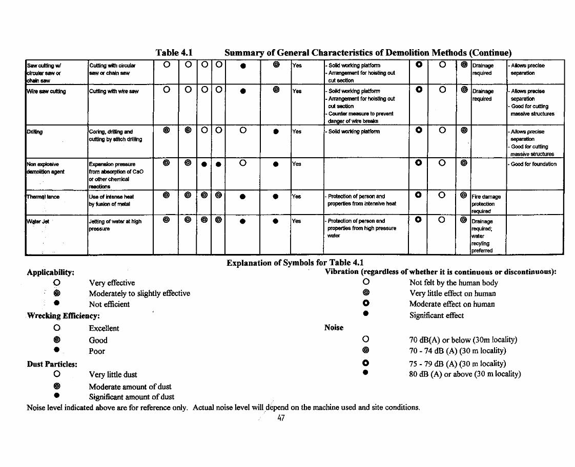
Table 4.1 Summary of General Characteristics of Demolition Methods (Continue)Saw cutting w/circular saw orchain saw
Wire saw cutting
Drilling
Non explosivedemolition agent
Thermal lance
WgerJet
Cutting with circularsaw or chain saw
Cutting with wire saw
Coring, drilling andcutting by stitch drilling
Expansion pressurefrom absorption of CaOor other chemicalreactions
Use of intense heatby fusion of metal
Jetting of water at highpressure
o
o
©
©
®
©
0
o
©
©
©
0
o
0
•
©
0
o
0
•
©
•
•
0
o
•
•
©
©
«
»
«
«
Yes
Yes
Yes
Yes
Yes
Yes
- Solid working platform- Arrangement for hoisting outcut section
- Solid working platform- Arrangement for hoisting outcut section
- Counter measure to preventdanger of wire breaks
- Solid working platform
- Protection of person andproperties from intensive heat
- Protection of person andproperties from high pressurewater
0
o
o
o
o
o
o
o
0
0
o
o
©
©
©
©
Drainagerequired
Drainagerequired
Fire damageprotectionrequired
Drainagerequired;waterrecylingDreferred
• Allows preciseseparation
- Allows preciseseparation
- Good for cuttingmassive structures
- Allows preciseseparation
- Good for cuttingmassive structures
- Good for foundation
Applicability:O Very effective© Moderately to slightly effective• Not efficient
Wrecking Efficiency:
O Excellent
© Good• Poor
Dust Particles:O Very little dust
© Moderate amount of dust• Significant amount of dust
Noise level indicated above are for reference only. Actual
Explanation of Symbols for Table 41Vibration (regardless of whether it is or
O
Noise
O
Not felt by the human bodyVery little effect on humanModerate effect on humanSignificant effect
70 dB(A) or below (30m locality)70 - 74 dB (A) (30 m locality)
75 - 79 dB (A) (30 m locality)80 dB (A) or above (30 m locality)
noise level will depend on the machine used and site conditions.47

(B) Demolition Sequence
Demolition sequence shall be determined according to actual siteconditions, restraints, the building layout, the structural layout andits construction. In general, the following sequence shall apply:
(1) All cantilevered slabs, canopies, verandahs and featuresattached to the external walls shall first be demolished priorto demolition of main building and its internal structures oneach floor;
(2) When demolishing the roof structure, all lift machine roomsand water tanks at high level shall be demolished in "topdown" sequence to the main roof level. In demolishing theexternal wall or parapet wall, the procedure as stated in4.2. L(D) shall apply.
(3) Demolition of the floor slabs shall begin at mid span andwork towards the supporting beams;
(4) Floor beams shall be demolished in the order as follows:
(a) cantilever beams;
(b) secondary beams; then
(c) main beams.
In the case when structural stability of beams are affected,e.g., due to lost of restraints, the affected beams shall bepropped prior to loss of support or restraint.
(5) Non-load bearing walls shall be removed prior todemolition of load bearing walls;
(6) Columns and load bearing walls shall be demolished afterremoval of beams on top;
(7) If site conditions permit, the first floor slab directly abovethe ground floor may be demolished by machine sitting onground level and mounted with demolition accessories.
(C) Cantilever Structures and Balconies
Cantilever structures, balconies and canopies may project out ofthe building over the pedestrian footpath or in some cases over aportion of the traffic lane. Temporary supporting structures and/or
48
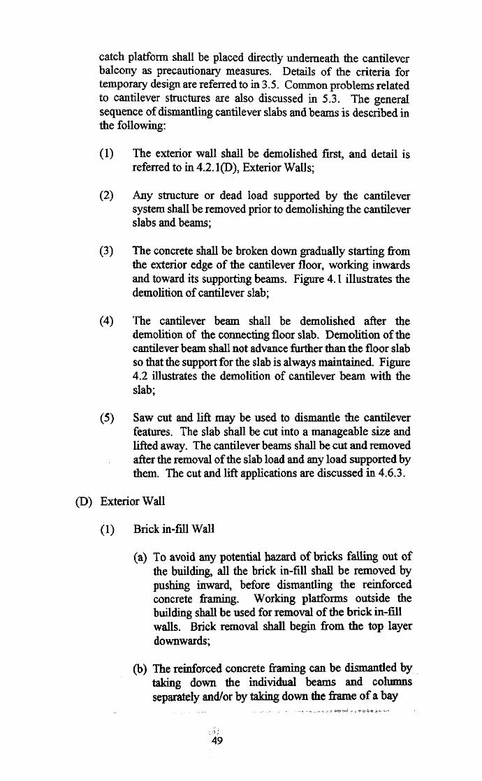
catch platform shall be placed directly underneath the cantileverbalcony as precautionary measures. Details of the criteria fortemporary design are referred to in 3.5. Common problems relatedto cantilever structures are also discussed in 5.3. The generalsequence of dismantling cantilever slabs and beams is described inthe following:
(1) The exterior wall shall be demolished first, and detail isreferred to in 4.2.1(D), Exterior Walls;
(2) Any structure or dead load supported by the cantileversystem shall be removed prior to demolishing the cantileverslabs and beams;
(3) The concrete shall be broken down gradually starting fromthe exterior edge of the cantilever floor, working inwardsand toward its supporting beams. Figure 4.1 illustrates thedemolition of cantilever slab;
(4) The cantilever beam shall be demolished after thedemolition of the connecting floor slab. Demolition of thecantilever beam shall not advance further than the floor slabso that the support for the slab is always maintained. Figure4.2 illustrates the demolition of cantilever beam with theslab;
(5) Saw cut and lift may be used to dismantle the cantileverfeatures. The slab shall be cut into a manageable size andlifted away. The cantilever beams shall be cut and removedafter the removal of the slab load and any load supported bythem. The cut and lift applications are discussed in 4.6.3.
(D) Exterior Wall
(1) Brick in-fill Wall
(a) To avoid any potential hazard of bricks falling out ofthe building, all the brick in-fill shall be removed bypushing inward, before dismantling the reinforcedconcrete framing. Working platforms outside thebuilding shall be used for removal of the brick in-fillwalls. Brick removal shall begin from the top layerdownwards;
(b) The reinforced concrete framing can be dismantled bytaking down the individual beams and columnsseparately and/or by taking down the frame of a bay
49

reinforcing 'bars to 'be cut after- breaking away the concrete
cantilever"beam toremain —
.4
direction ofconcrete demolition
J I
- cantileverbeam toremain
regular beamto remain
PLAN
FIGURE 4.1 DEMOLITION OF CANTILEVER REINFORCEDCONCRETE SLAB
50
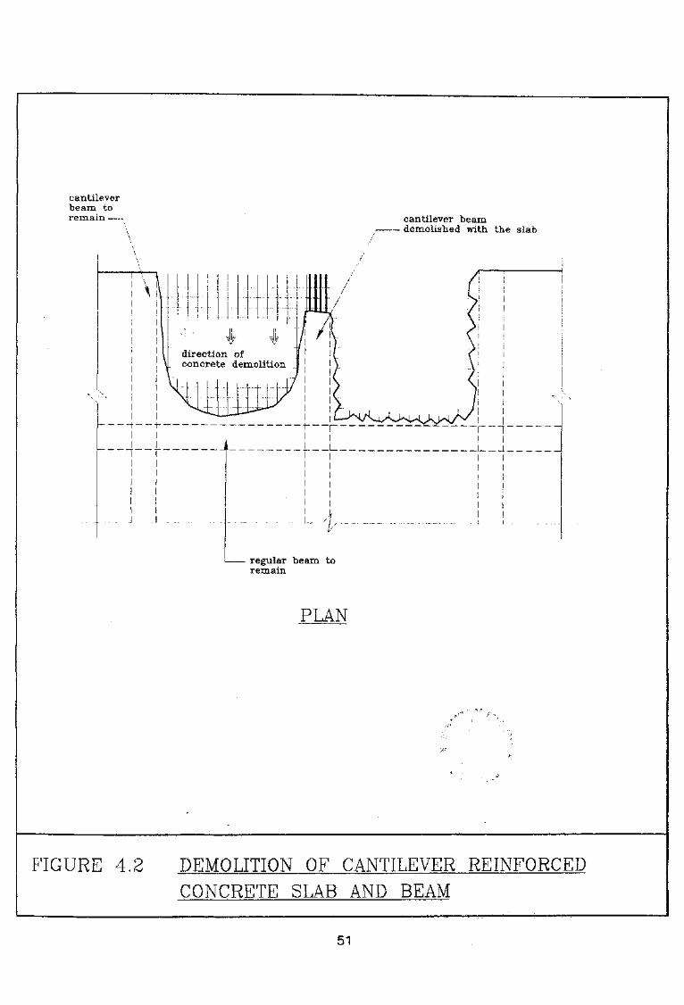
cantileverbeam toremain — -. cantilever beam
• demolished with the slab
\\\
~~"
\ I
direction ofconcrete demolition
"~
regular beam toremain
PLAN
FIGURE 4.2 DEMOLITION OF CANTILEVER REINFORCED
CONCRETE SLAB AND BEAM
51
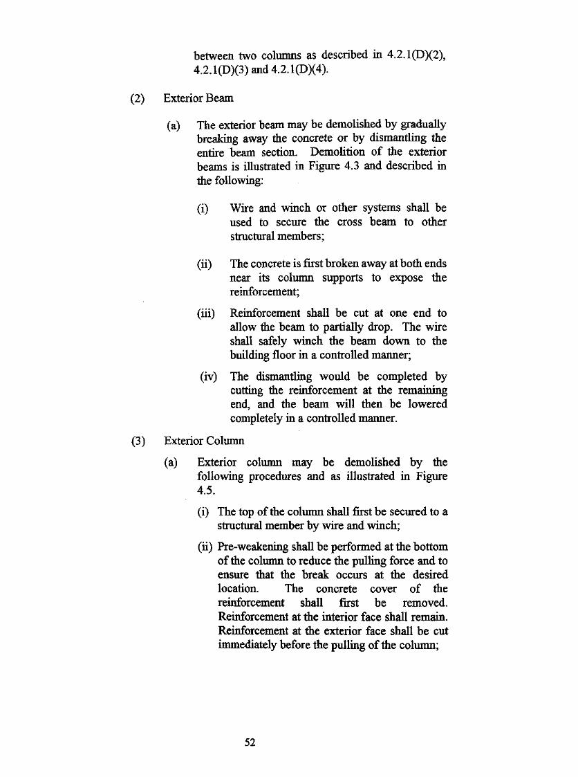
between two columns as described in 4.2.1(D)(2),4.2.1(D)(3)and4.2,l(D)(4).
(2) Exterior Beam
(a) The exterior beam may be demolished by graduallybreaking away the concrete or by dismantling theentire beam section. Demolition of the exteriorbeams is illustrated in Figure 4.3 and described inthe following:
(i) Wire and winch or other systems shall beused to secure the cross beam to otherstructural members;
(ii) The concrete is first broken away at both endsnear its column supports to expose thereinforcement;
(iii) Reinforcement shall be cut at one end toallow the beam to partially drop. The wireshall safely winch the beam down to thebuilding floor in a controlled manner;
(iv) The dismantling would be completed bycutting the reinforcement at the remainingend, and the beam will then be loweredcompletely in a controlled manner.
(3) Exterior Column
(a) Exterior column may be demolished by thefollowing procedures and as illustrated in Figure4.5.
(i) The top of the column shall first be secured to astructural member by wire and winch;
(ii) Pre-weakening shall be performed at the bottomof the column to reduce the pulling force and toensure that the break occurs at the desiredlocation. The concrete cover of thereinforcement shall first be removed.Reinforcement at the interior face shall remain.Reinforcement at the exterior face shall be cutimmediately before the pulling of the column;
52

PLAN
span to be demolished
(8m max.)
cut g cut 3
wire anchored atwinch or internalcolumn/beam withpulley
rubber tires(optional)
additional external beamtied to existing beam/column may be requiredfor corner section
ivire anchored at•winch or internalcolumn/beam with•winch
external beam tied toexisting beam/column
ELEVATION
l.Prop all span of external beam.2. Tie the span of beam to be demolished.
(details of the connection may refer to figure 4.4)3. Remove props at span to be demolished.4. Expose all reinforcement.5. Cut reinforcement at cut 1, cut 2, and cut 3.6. Lower the end at cut 1 & cut 2.7. Cut reinforcement at cut 4.8. Lower the beam.
Note : The tie wire are indicative. If there are permanent anchors or liftingmachines available tie wire arrangements may be simplified to suit.
FIGURE 4.3 DEMOLITION : OF EXTERNAL BEAM
53
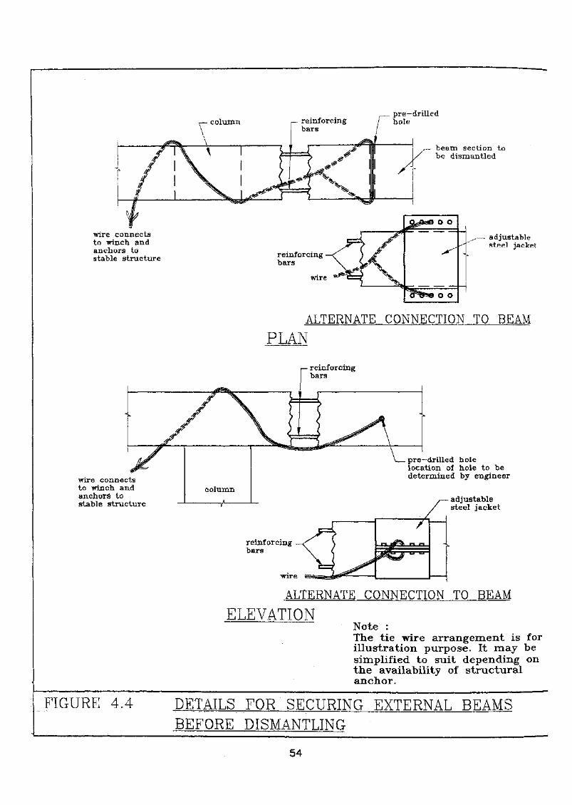
• columnpre—drilledhole
— beam section tobe dismantled
wire connectsto winch andanchors tostable structure
^.— adjustablestfiel jacket
ALTERNATE CONNECTION TO BEAM
PLAN
P- reinforcingbars
wire connectsto winch and•anchor^- tostable structure
reinforcingbars
pre-drilled holelocation of hole to bedetermined by engineer
adjustablesteel jacket
ALTERNATE CONNECTION TO BEAM
ELEVATIONNote' : :The tie wire arrangement is forillustration purpose; It.-..may- besimplified to suit depending on- •the availability of structuralanchor.
FIGURE 4.4 DETAILS FOR SECURING EXTERNAL BEAMSBEFORE DISMANTLING
54

of beam
EXTERIOE
attached to tie wire and winchsystem or excavator arm.
of beam
EXTERIOR
directionof fall
INTERIOR
SECTION ALEGEND :
Q Reinforcing bar to remain
5& Reinforcing bar to be cut
tie wire to existing structurefor additional safety(exterior columns only)
NOTES : '1. Secure the column by wire & winch to:
existing structure or excavator arm.'2-. Pre—weakening at the bottom of column
i) Break away. the concrete to expose thereinforcing bars.,
ii) cut the reinforcing bars at the exterior halfof the column. Cutting shall be performedimmediately', prior "to. pulling. . , :
3. Pulling down the column in a controlled motion.
FIGURE 4.5 PRE-WEAKENING AND DISMANTLING OF COLUMN
55
(iii) After pre-weakening, the column shall bepulled down by the wire and winch towardsthe interior in a controlled manner.
(4) Exterior R. C. Frame
(a) The exterior R. C. frame may be demolished insections. The demolition procedures are generallydescribed in the following:
(i) For manual demolition, the optimum sectionof the frame to be demolished shall be a baybetween the two adjacent columns but shallnot be wider than 3 m;
(ii) The frame section shall be secured to otherstructural members with wire and winchbefore disconnecting the framing from theremaining structure;
(iii) Pre-weakening shall be performed at thebottom of the two columns. The pre-weakening of the columns shall follow4.2.1(0X3);
(iv) The reinforcing bars connecting the beamsshall be cut off after pre-weakening. Theframing shall be pulled down by exertingforce through winch and pulley system.
(5) Reinforced Concrete Wall
(a) Load Bearing Wall
Reinforced concrete walls may be demolished bycutting down the wall into manageable sections.The width of the wall shall not be wider than 2 m.Demolition of the reinforced concrete wall sectionsis illustrated in Figure 4.6 and described in thefollowing:
(i) Before demolition begins, wire and winchsystems shall be used to secure the wallsection;
(ii) Pre-weakening at the bottom of the wall shallbe performed, particularly if the wall sectioncontains columns. The concrete along the cutline of the interior face of the wall section
56

additional tie wire forexternal walls onlysize and no. of tie wireshall be determined by theESE and shall be specifiedon the demolition plans
wall tie anchored to interiorcolumn or beam
reinforcing bars in the beam connectingto exterior column lo remainfor additional support
begin with section at mid span.break away a vertical groove withsome reinforcing bars remain tosupport the structure
EXTERNAL R.C. WALL (VIEW FROM INSIDE)
Break outthe concreteon the interiorface.reinforcingbars toremain
tie wire to pullthe wall down
tie wire for additionsafety (exterior walls
pulley
Cutting away thereinforcing barsconnecting thewall section.Reinforcing barat the bottomto remain.Pulling down thewall section bywire and winchin a controlledmotion.
\__ pulley
SECTION Aprior to pulling
SECTION ANOTES :This method may apply to bothhand-felling of interior andexternal walls.
FIGURE 4.6 FELLING OF A REINFORCED CONCRETE WALL
57
shall be broken away by hand held tools.Pre-weakening of columns shall follow4.2.1(D)(3). The operation be careful tominimise debris from falling out from thebuilding;
(iii) After the concrete along the cut Ike isremoved, the reinforcing bars along thevertical cut line shall be separated. Forceshall be exerted through the wire and winchsystems to pull the wall down into thebuilding.
(b) Non-Load Bearing Wall
For non-load bearing walls or walls with heavy crossbeams, the dismantling procedures are similar to thatof the load bearing wall except that the cross beamsare dismantled separately from the building walls.Figure 4.7 illustrates the felling of non-load bearingwall sections separately from the cross beam.
(E) Floor Slabs
Reinforced concrete floor slab shall be demolished by graduallybreaking away the concrete. The reinforcement shall remain andbe cut off after the concrete is broken away. The sequence fordemolition of typical floor slabs are discussed in the following;
(1) Two way slab
The two way slab is supported by beams or structuralmembers on all four sides. Demolition of the slab shallbegin in the middle of the slab and advance towards thesides in all 4 directions. Figure 4.8 illustrates thedemolition of two way slab.
(2) One way slab
The breaking of concrete shall begin at the unsupported endand proceed in strips perpendicular to the supporting beamor structural member. The strips shall be demolished fromtheir centre towards the supports in both directions.
(3) Flat slab
Demolition of flat slab shall begin at the centre of the baybetween the supporting columns and proceed outwards to
58
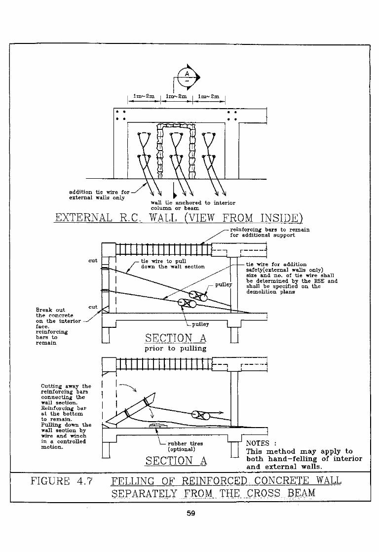
o «
9 «
addition tie wire forexternal walls only -A\ I V\ \\
wall tie anchored to interiorcolumn or beam
EXTERNAL R.C. WALL (VIEW FROM INSIDE)
cut
Break outthe concreteon the interiorface.reinforcingbars toremain
tie wire to pulldown the wall section
reinforcing bars to remainfor additional support
tie wire for additionsafetyf external walls only)size and no. of tie wire shallbe determined by the RSE andshall be specified on thedemolition plans
\— pulley
SECTION Aprior to pulling
Cutting away the• reinforcing barsconnecting thewall section.Keinforcing barat the bottomto remain.Pulling down thewall section "bywire and winchin a controlledmotion. i— rubber tires
(optional)
SECTION A
NOTES :This method may apply toboth hand-felling of interiorand external walls.
FIGURE 4.7 FELLING OF REINFORCED CONCRETE WALLSEPARATELY FROM,, THE. CROSS. BEAM
59
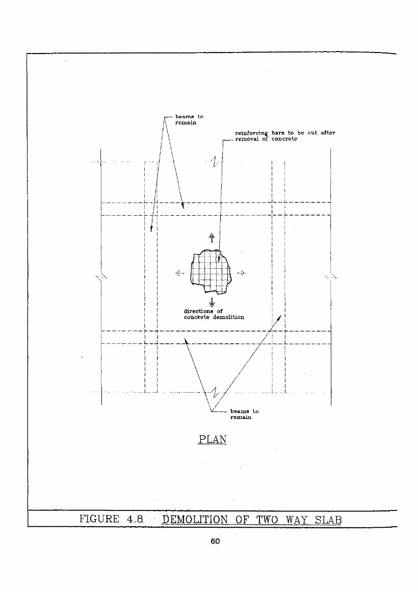
beams toremain
reinforcing "bars to "be cut afterremoval of concrete
directions ofconcrete demolition
PLAN
FIGURE 4.8 DEMOLITION OF TWO WAY SLAB
60
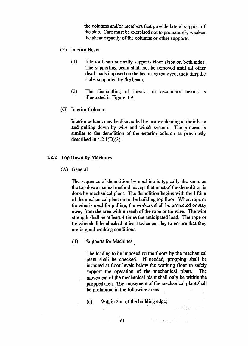
the columns and/or members that provide lateral support ofthe slab. Care must be exercised not to prematurely weakenthe shear capacity of the columns or other supports.
(F) Interior Beam
(1) Interior beam normally supports floor slabs on both sides.The supporting beam shall not be removed until all otherdead loads imposed on the beam are removed, including theslabs supported by the beam;
(2) The dismantling of interior or secondary beams isillustrated in Figure 4.9.
(G) Interior Column
Interior column may be dismantled by pre-weakening at their baseand pulling down by wire and winch system. The process issimilar to the demolition of the exterior column as previouslydescribed in 4.2.1(D)(3).
4.2.2 Top Down by Machines
(A) General
The sequence of demolition by machine is typically the same asthe top down manual method, except that most of the demolition isdone by mechanical plant. The demolition begins with the liftingof the mechanical plant on to the building top floor. When rope ortie wire is used for pulling, the workers shall be protected or stayaway from the area within reach of the rope or tie wire. The wirestrength shall be at least 4 times the anticipated load. The rope ortie wire shall be checked at least twice per day to ensure that theyare in good working conditions.
(1) Supports for Machines
The loading to be imposed on the floors by the mechanicalplant shall be checked. If needed, propping shall beinstalled at floor levels below the working floor to safelysupport the operation of the mechanical plant. Themovement of the mechanical plant shall only be within thepropped area. The movement of the mechanical plant shallbe prohibited in the following areas:
(a) Within 2 m of the building edge;
61
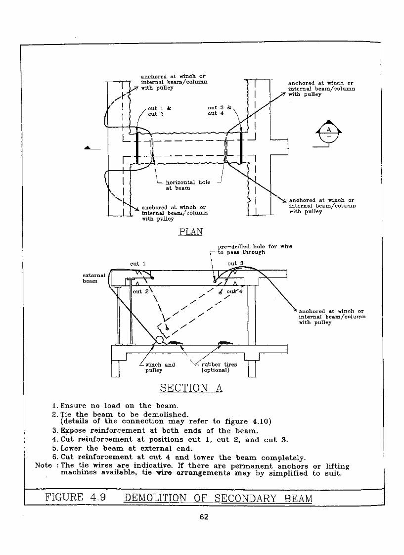
T^xt-fanchored at -winch, orinternal be am/ columnwith pulley
cut 1 &cut 2
cut 3 &cut 4
i-iL_.
r
^—.-Ji
l— horizontal hole —'at beam
anchored at winch orinternal beam/columnwith pulley
anchored at "winch orinternal beam/columnwith pulley
anchored at winch orinternal be am/columnwith pulley
PLAN
pre-drilled hole for wireto pass through
cut 1
externalbeam
anchored at -winch orinternal beam/coluxnnwith pulley
SECTION A
1. Ensure no load on the beam.2. Tie the beam to be demolished.
(details of the connection may refer to figure 4.10)3. Expose reinforcement at both ends of the beam.4. Cut reinforcement at positions cut 1, cut 2, and cut 3.5. Lower the beam at external end.8. Cut reinforcement at cut 4 and lower the beam completely.
Note : The tie wires are indicative, If there are permanent anchors or liftingmachines available, tie wire arrangements may by simplified to suit.
FIGURE 4.9 DEMOLITION OF SECONDARY R K A M
62
- main beam
wire connectsto winch andanchored tostable structure
reinforcingbars
reinforcingbars
beamsection
ALTERNATE CONNE(
adjustablesteel jacket
TO BEAM
PLAN
main beambeamsection -
adjstablesteel jacket
wire connectsto winch andanchors tostable structure
pre—drilled holefor wire to passthrough, locationof hole shall bedetermined byengineer
•— reinforcingbars
ALTERNATE CONNECTION TO BEAM
ELEVATION
Note :The wire arrangement is forillustration purpose. It may besimplified to suit depending onthe availability of structuralanchor.
FIGURE 4.10 DETAILS FOR SECURING SECONDARY BEAMSBEFORE; DISMANTLING ;

(b) 1 m of any floor openings; or
(c) any cantilever structures.
Markings such as ribbons, paints or other appropriatemeans shall be used to identify the propped area and limitsof the mechanical plant movement. The extent of thepropping shall be determined based on the anticipatedoperation, the allowable loading on the floor slabs and thesite conditions. Design criteria for the proppingrequirements are referred to in 3.5.5.
(2) Lifting of machinery
The mechanical plant shall be lifted onto the roof of thebuilding by the use of mobile crane or other appropriatemeans as approved by the Registered Structural Engineer .Prior to the lifting operation, propping shall be installed onthe floors beneath the roof in accordance with the approveddesign. The crane shall be properly tested, examined andoperated in accordance with the Factories and IndustrialUndertakings (Lifting Appliances and Lifting Gear)Regulations. The operating area shall be blocked off duringthe lifting operation. Approval from the Police andTransport Departments shall be obtained prior to theoperation if temporary road closure is required.
(3) Temporary Ramp Construction
The machine shall descend down to the next floor by meansof a ramp. The ramp may be a temporary structure or otherappropriate design. The slope of the ramp shall be nosteeper that 1.75 to 1 or as recommended by the machine
manufacturer. Temporary structure shall be designedand constructed in accordance with 3.5. Proppingrequirements for the temporary access ramp are referred toin 3.5.5.
(B) Demolition Sequence
Demolition sequence shall be determined according to the actualsite conditions, restraints, original building layout and itsconstruction. In general, the following sequence shall apply:
(1) prior to demolition of internal floors, all cantilever slabs andbeams, canopies, and verandahs shall first be demolished;
64
(2) the structural elements, in general, be demolished inthe following sequence:
- slab;- secondary beams;- main beams.
- (3) mechanical plant shall descend from the floors withtemporary access ramp;
(4) when a mechanical plant has just descended from the floorabove, the slabs and beams, in two consecutive floors maybe demolished by the mechanical plant simultaneously. Themechanical plant may work on structural elements on thesame floor and breaking up the slabs on the floor above;
(5) the wall panel, including beams and columns shall bedemolished by gradually breaking down the concrete or bypulling them down in a controlled manner;
Figure 4.11 illustrates the typical sequence of top down methodwith mechanical equipment.
(C) Cantilever Canopies and Balconies
Demolition of cantilever canopies and balconies may criticallyaffect public safety and must be performed with extreme caution.Temporary supporting structures and/or catch platform shall beplaced directly underneath the cantilevers or balconies. Commonproblems related to cantilever structure are discussed in 5.3. Theprocess of demolition of the cantilever structures is described inthe following:
(1) The exterior wall that forms a part of the cantileverstructure or balcony shall be removed first. This is furtherdiscussed in 4.2.2(D) exterior wall;
(2) The floor slab and cantilever beam may be demolished insections. Demolition of cantilever slab is illustrated inFigure4.12;
(3) The machine aim with wire passing through the slab sectionshall be used to stabilise the structure while the cutting isperformed;
65

h :im H- excavatortravel limit
-scaffolding
X
catchfan—>'
Ji igl Mj
1. Demolition of Slabs and Beams
catchf an
.propping
propping
.2. Continue Demolition of Slabs and Beams
FIGURE 4.11 TYPICAL SEQUENCE OF TOP DOWN METHODWITH MECHANICAL EQUIPMENT (sheet 1 of 3)
66
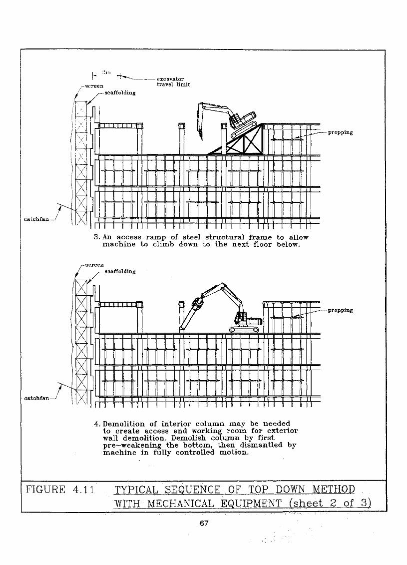
uexcavatortravel limit
— scaffolding
catchfan-
propping
3. An access ramp of steel structural frame to allowmachine to climb down to the next floor below.
-screen-scaffolding
catchfan
\
/
A
-propping
4. Demolition of interior column may be neededto create access and working room for exteriorwall demolition. Demolish column by firstpre-weakening'the bottom, then dismantled bymachine in fully controlled motion.
FIGURE 4.11 TYPICAL SEQUENCE OF TOP DOWN METHODWITH MECHANICAL EQUIPMENT (sheet 2 of 3)
67
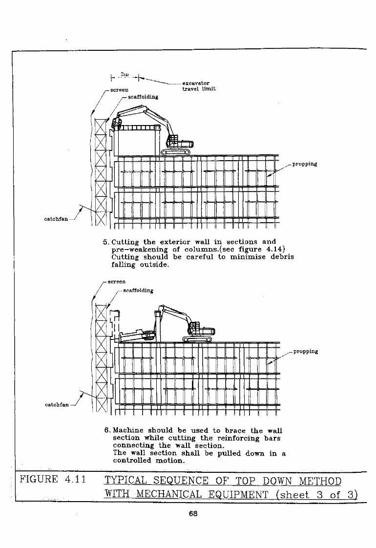
catchf an -
catchfan
excavatortravel limit
.-propping
5. Cutting the exterior wall in sections andpre-weakening of columns,(see figure 4.14)Cutting should be careful to minimise debrisfalling outside.
- screen
- scaffolding
.— propping
6. Machine should be used to brace the wallsection while cutting the reinforcing barsconnecting the wall section.The wall section shall be pulled down in acontrolled motion.
FIGURE 4.11 TYPICAL SEQUENCE OF TOP DOWN METHODWITH MECHANICAL EQUIPMENT (sheet 3 of 3)
68

excavatortravel limit
supportingplatform
propmgs -
machine shallbe operated onlevel ground
proppings
CASE 1. MACHINE MOUNTED ON SUSPENDED FLOOR
propmgs
proppings
CASE 2. MACHINE MOUNTED ON GROUND
FIGURE 4.12 DEMOLITION OF CANTILEVER SLAB BY MOBILEMACHINE (CONVENTIONAL METHOD)(SHEET 1 OF 2)
69
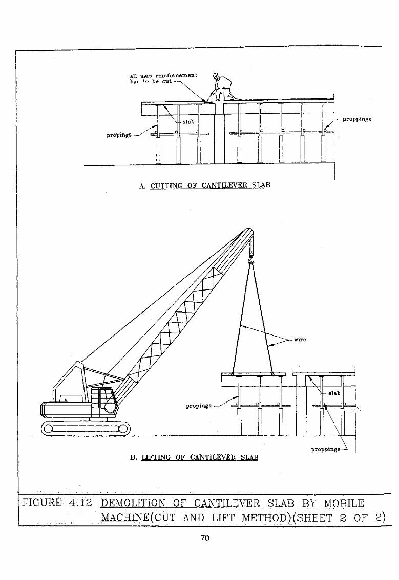
all slab reinforcementbar to be cut
proppings
A. CUTTING OF CANTILEVER SLAB
proppings -B. LIFTING OF CANTILEVER SLAB
FIGURE 4:12 DEMOLITION OF • "CANTILEVER SLAB BY MOBILEMACHINEfCUT AND LIFT METHOD)(SHEET 2 OF 2)
70
(4) Cuttings may be performed by jack or pneumatichammer for the concrete and oxy-acetylene flame cutter forthe reinforcements. The concrete be broken away firstbefore the cutting of reinforcement. Alternatively thereinforced concrete slab may be cut by saw cutting;
(5) The slab shall be lifted into the building by a derrick arm.
(D) Exterior Wall
Demolition of exterior wall shall be proceeded with extremecaution. The exterior wall may be demolished in sections bymechanical plant. The width of wall section shall be determinedby the RSE. The mechanical plant shall have adequate workingcapacity to safely handle the weight of the wall sections. A shortspan of the slab, about 300 mm, attached to the external beam atthe top of the wall, may be left in order to keep the loadingresultant of the exterior wall further into the building.
(1) Brick in-fill wall
Demolition of the brick-in-fill wall is generally described inthe following:
(a) The in-fill bricks shall first be manually removed.The brick shall be removed from the top layer downby pushing in from outside. Work platforms erectedoutside the building may be used for this operation;
(b) After the in-fill bricks are removed. The reinforcedconcrete frame may be demolished by dismantlingthe framing sections as described in 4.2.2(D)(3).
(2) Exterior Column
(a) The excavator arm with wire or hydraulic crusherattachment shall be used to brace the column;
(b) Pre-weakening shall be performed at the bottom ofthe columns, similar to the process described in
(c) After pre-weakening, the column shall be pulleddown in a controlled motion into the building by theexcavator arm.
(d) Demolition inside the building by the excavator arm.
71
(3) Exterior R.C. Frame
Dismantling of the exterior R.C. frame, is illustrated inFigure 4.13 and is described in the following:
(a) The concrete along the proposed cut-Ike shall bebroken first. The reinforcing bars shall be kept tostabilise the structure. The excavator arm shallsecure the reinforced concrete framing;
(b) Pre-weakening may be performed at the bottom ofthe columns as described in Figure 4.5. Theexcavator arm shall continue to stabilise the framewhile cutting the reinforcing steel at thedisconnecting points;
(c) The excavator arm shall pull and guide the framesafely onto the floor.
(4) Reinforced Concrete Wall
The process of demolishing a reinforced concrete wallsection is similar to that of a reinforced concrete frame.Demolition of a reinforced concrete wall section isillustrated in Figure 4.14 and is described in the following:
(a) The reinforced concrete wall shall be verticallyseparated from the remaining wall by breaking awaythe concrete. The width of the wall section shall bedetermined by the Registered Structural Engineer.The reinforcing bars shall remain to provide supportto the wall section;
(b) If the wall section contains columns, pre-weakeningshall be performed at the level where the wall is tobe separated. Pre-weakening of column is referredtoin4.2.1(D)(3);
(c) The machine arm shall be used to secure the wallsection during the cutting of the reinforcementsalong both sides of the wall section;
72

Hydraulic crusher attachment —
• v
Excavator Arm with -wireto stablise the framein lieu of hydrauliccrusher
Pre-weaken/ at the bottom.
of column
1. Excavator arm with wire or hydraulic crusherattachment secures the R.C. Frame.
2. The length of the frame section shall be determinedby the RSE.
3. Pre-~ weakening of the concrete column at the bottomby breaking out the concrete cover to expose thereinforcing bars. Only the reinforceing bars at theexterior face, where the columns fall away from,shall be cut. (see Figure 4.5)
4. Excavator arm pulls down the frame in a slow andcontrolled motion.
FIGURE 4.13 DEMOLITION OF R.C. FRAME BY EXCAVATOR
73

width of eachbe
reinforcement barto remain
1. Breaking away the concrete along vertical slotsto separate the wall section.Width of wall section shall be determined by the RSE.Reinforcing bars shall be left to stabilisethe section.Breaking of concrete shall be done cautiously tominimise debris from falling outside the building.
FIGURE 4.14 DEMOLITION OF REINFORCED CONCRETE WALLBY EXCAVATOR (sheet 1 of 3)
74
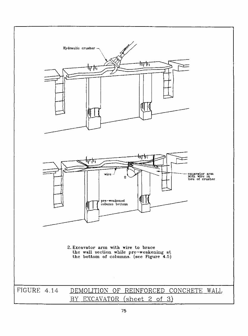
Hydraulic crustier
pre-weakenedcolumn bottom
•— excavator armwith wire inlieu of crusher
2. Excavator arm with wire to bracethe wall section while pre-weakening atthe bottom, of columns; (see Figure 4.5)
FIGURE 4.14 DEMOLITION OF REINFORCED CONCRETE WALLBY EXCAVATOR (sheet 2 of 3)
75

pre-weakens acolumn bottom
cutting thereinforcingbars while theexcavator armcontinue tobrace the wallsection
3. Machine continue to brace the wail section, whilecutting the reinforcing bars,Reinforcing bar at the bottom to remain.After cutting off reinforcements, excavator armpulls the wall down in a controlled motion.
FIGURE 4.14 DEMOLITION OF REINFORCED CONCRETE WALLBY EXCAVATOR (sheet 3 of 3)
76
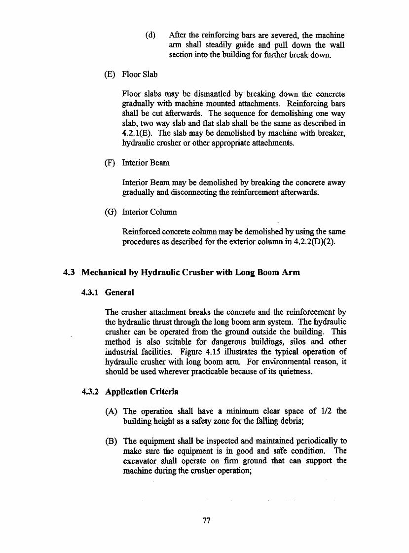
(d) After the reinforcing bars are severed, the machinearm shall steadily guide and pull down the wallsection into the building for further break down.
(E) Floor Slab
Floor slabs may be dismantled by breaking down the concretegradually with machine mounted attachments. Reinforcing barsshall be cut afterwards. The sequence for demolishing one wayslab, two way slab and flat slab shall be the same as described in4.2.1(E). The slab may be demolished by machine with breaker,hydraulic crusher or other appropriate attachments.
(F) Interior Beam
Interior Beam may be demolished by breaking the concrete awaygradually and disconnecting the reinforcement afterwards.
(G) Interior Column
Reinforced concrete column may be demolished by using the sameprocedures as described for the exterior column in 4.2.2(D)(2).
4.3 Mechanical by Hydraulic Crusher with Long Boom Arm
4.3.1 General
The crusher attachment breaks the concrete and the reinforcement bythe hydraulic thrust through the long boom arm system. The hydrauliccrusher can be operated from the ground outside the building. Thismethod is also suitable for dangerous buildings, silos and otherindustrial facilities. Figure 4.15 illustrates the typical operation ofhydraulic crusher with long boom arm. For environmental reason, itshould be used wherever practicable because of its quietness.
4.3.2 Application Criteria
(A) The operation shall have a minimum clear space of 1/2 thebuilding height as a safety zone for the falling debris;
(B) The equipment shall be inspected and maintained periodically tomake sure the equipment is in good and safe condition. Theexcavator shall operate on firm ground that can support themachine during the crusher operation;
77
1/2 H MIN.
FIGURE 4.15 DEMOLITION BY HYDRAULIC CRUSHER WITHLONG ARM BOOM
78

(C) Except for special section of the structure shallbe in a top to stability of thestructure;
(D) Debris may be used to up a for the excavator tothe of reach. It is the debris is densely
compacted to support the of the excavator. The platformmust be flat and the slope be stable. The height of the buildup be to 3 m. The side slope of thetemporary platform not be steeper than 1:1 (horizontal tovertical) unless the condition allows a steeper slope. The slope ofaccess ramp for the machine shall be in accordance with themanufacturer recommendation. The width in both directions ofthe platform shall be at least one and one-half the length of themachine to allow safe manoeuvre during the demolition operation;
(E) To minimise the dust impact, the structure shall be pre-soaked withwater before demolition. Water shall be continuously sprayedduring the crushing operation;
(F) Debris may fall out of the building during the demolition. The siteshall be completely fenced off. There shall be 24-hours guardedsecurity to allow only authorized personnel for site access.During the operation of the crusher there shall be no worker withinthe machine operating area or inside the building;
(G) The crusher operator shall possess the essential skills andsignificant experience in the crusher operation. There shall be aspot person to assist in. the operation and alert the operator of anypotential problem during the operation.
4.4 Wrecking Ball
4.4.1 General
The wrecking ball application consists of a crane equipped with a steelball. The destruction of the building is by the impact energy of the steelball suspended from the crawler crane. The wrecking ball operatesoutside the building. This method is suitable for dilapidated buildings,silos and other industrial facilities. However, the operation requiressubstantial clear space. The application also demands high level skilloperators and well-maintained equipment. Figure 4.16 illustrates theoperation of Wrecking Ball
79

JIB HEAD 3m ABOVEBUILDING BEING DEMOLISHED
T
1/2 H MIN.
VERTICAL DROP METHOD
connDDDD
D'DDD1/2 H MIN.
SWING IN-LINE METHOD
FIGURE 4,16 OPERATION OF WRECKING BALL
80
4.4.2 Application Criteria
The recommended criteria for the use of wrecking ball are presented inthe following:
(A) Except for special application, the. balling of each section of thestructure shall proceed from top to bottom. Care be taken to
• maintain the stability of the structure;
(B) Recommended techniques for the wrecking ball operationsinclude:
(1) Vertical Drop - free falling of the wrecking ball onto thestructure;
(2) Swing in line - swinging of the ball in-line with the jib. Asecond dragline will normally connect to the ballhorizontally to control the ball motion. The ball shall beswung into the building. The ball shall strike at the top ofthe member so as to avoid the member from falling outsidethe building.
Slewing the jib is not recommended. The motion of the ball byslewing the jib is difficult to control. It demands expert knowledgeof the machine and structure as well as operating skills to safelyperform the task. Slewing can potentially induce a tremendousamount of stress on the jib, as such, its use shall be avoided.
(C) The jib or boom shall be operated with no less than 3 m above theportion of the structure being demolished;
(D) Clear space for operation between the crane and the structurebeing demolished shall be 50% of the height of structure, the cleardistance between the site boundary and the building to bedemolished shall not be less than 50% of the building height plusan additional 6 m for the crane to manoeuvre, this criteria shallapply to all sides of the building to be demolished by wreckingball;
(E) The demolition ball shall be connected with swivel type anti-spindevice to prevent twisting and tangling of the wire duringoperation;
(F) The wire and boom of the machine used for balling shall have arated capacity, at the working radius, of at least 5 times the weightof the ball;
81
(G) The strength of the wire shall be at least twice the tensile strengthof the steel reinforcement of the floor slab and beams.The wire allows the pullout of the wrecking ball frompotential traps;
(H) To ensure that the crane is in good condition, the wire connectingto the ball, the boom components and connecting pins shall beinspected twice daily;
(I) A sufficient length of the wire shall be provided to allow the ball todrop to the lowest working level plus an addition of 10% of thewire length and no less than 3 drums. For swing in-line method,there shall be sufficient length of the dragline wire to allow the ballto fall in the event that the ball is entangled with the falling debris;
(J) The operation shall not be performed adjacent to overhead powerlines;
(K) The site shall be entirely fenced off to forbid public access. A24-hour security guard shall be assigned to the site to enforce theaccess restriction; depending on the relative location between thefence and the building, and fence shall be designed to withstandaccidental impact by the wrecking ball;
(L) During the use of the demolition ball, except for the craneoperator and the spot person, all other workers shall be kept awayfrom the demolition ball's working radius. No body shall stayinside the building;
(M) To minimise the dust impact on the surrounding area, the structureto be demolished shall be pre-soaked with water beforedemolition. Water spraying shall continue on the structure duringdemolition;
(N) Since the safety and success of the project depend highly on theoperator and site personnel, the operator must have provenexperience and skill for operating the wrecking ball to thesatisfaction of the approval authority;
(O) A spot person shall be on site during the operation to assist theoperator and to ensure site safety. The spot person shall haveextensive knowledge and experience in the use of wrecking ball.The qualification and experience of the spot person shall beequivalent-to those of the wrecking ball operator.
82
4.5
43.1
If the Contractor intends to blast a building structure, the Contractorshall cany out a comprehensive Risk Assessment Report and anEnvironmental Assessment Report on the effect of implosion on theaffected neighbourhood. With positive results on both the riskassessment and environmental impact assessment and agreed by therelevant approval Authority, through the central processing of theBuildings Department, the Contractor may begin studying the structureof the building and develop a blasting design. The design may includepre-weakening of the structure, the strategy in placement of theexplosives and time delay so that the building will collapse in a safemanner. Pre-weakening of the structure may include cutting out aportion of the shear walls and other structural elements. A test blastmay be conducted to verify the strength of the structural member and tofine tune the explosive design. Protection of the adjacent properties andhabitats is also an important consideration.
4.5*2 General Concerns
General concerns and good practices in controlled demolition byblasting are discussed in the following:
(A) Pre-weakening of the structure shall be designed to ensure thestructural stability before the implosion;
(B) To minimise the dispersion of building debris into adjoining landafter blasting, a trench or bund wall shall be installed outside thebuilding to contain the debris, unless a basement exists;
(C) A good design will cause the structure to fall towards the centre ofthe building and/or within the protected area;
(D) A good design will provide adequate and sufficient time delay toallow only one or two floors of the building debris to fall onground level at a time in order to limit the magnitude of the impacton the ground;
(E) The design must also identify an exclusion zone to evacuate allresidents or inhabitants during the blasting. The impacts of noiseand dust generated during the blasting shall be considered. Radiusof the typical exclusion zone shall not be less than 2.5 times thebuilding height;
83
(F) If there are slopes and earth retaining walls or features, ageotechnical assessment shall be conducted to ensure that theblasting will not affect the stability of these features;
(G) The entire site shall be under 24-hour security from the installationof explosive until final blasting. and storage ofexplosives shall be in conforaiance with the Dangerous GoodsOrdinance, any requirements of the Commissioner of Mines andother relevant regulations. The implosion expert shall have provenexperience and track records in design and supervision of blastingsimilar building structures to the satisfaction of the Commissionerof Mines. The blasting expert shall have acquired the relevanttraining and practical experience in using the proposed explosives.The blasting expert shall obtain from the Commissioner of Minesan authorization to cany out blasting. All personnel must beevacuated from the site before and during blasting;
(H) The contractor must co-ordinate with the government and localcommunity to determine the best procedures in notification,schedules for the events, traffic routing, design for the sequence ofevents, evacuating residents, clear out personnel from the buildingand assigning responsibilities during blasting. For the purpose ofcrowd control, blasting should be carried out in the early morningof a Sunday or public holiday;
(I) An emergency plan shall be prepared to handle emergencysituations such as premature explosion, misfire or interruption dueto bad weather including thunder and lightning;
(J) After the explosion, the blasting expert must check to make surethat there is no unfired explosive left on site. The entire area mustremain clear and under security control until the unfiredexplosives have been detonated or safely dealt with by the blastingexpert;
(K) As far as practicable, non-electrical initiation systems should beused to avoid the risk of pre-mature detonation by stray currents,external electro-magnetic waves or radio frequencies. Theinstallation shall include a redundant system to ensure successfuldetonation. Nitroglycerine based exposives are not permitted tobe used.
(L) The contractor must provide evidence of his capability to safelyperform the demolition and shall illustrate to the approvingauthorities that the procedures are safe;
(M) The mode of collapse shall be demonstrated to ascertain that:
84
(1) no part of the building will fall beyond the protected area;
(2) the impact of the structural collapse will not causesignificant vibration affecting
(a) any underground tunnels;
(b) any underground utilities; and
(c) any adjoining properties.
(N) The structural safety of the building to be imploded shall bechecked and certified to be sound and safe at all stages prior toimplosion.
46 Other Methods
4.6.1 Noil Explosive Demolition Agent
Non Explosive Demolition Agent (NEDA) is a static demolition agent.When the reaction takes place in a confined drill hole, the NEDAgenerates an expansive pressure to crack and break concrete and stone.
The NEDA is a suitable application in a restrictive environment wherenoise,.flying debris and vibration are less tolerated. A drilling patternshall first be designed. For large projects, test breaking shall beperformed. The NEDA shall be mixed with water to form a slurry andimmediately placed into the pre-drilled holes. The loading intensity andwater content shall be controlled to optimise the expansive pressure andprevent blow-out of the NEDA. The breaking effect of NEDA isrelatively small comparing to explosives. Secondary efforts arerequired to further break down and remove the debris by mechanicalmeans.
NEDA may be used on foundation works, pile caps or structures that arefully supported.
When used in rock, NEDA should be contained within strong, flexible,impermeable bags to prevent uncontrolled entry into rock joints.
4.6.2 Saw Cutting
Saw cutting is suitable for alteration and additional works whereaccuracy in the cutting is important and the tolerance to noise andvibration is very limited. It can be used to cut concrete slabs and wall
85
elements into segments. An entire building may be dismantled by sawcutting. Saw cutting generally includes conventional disc saw andchain saw, diamond core stitch drilling and wire saw.
(A) Wire Saw Cutting
Wire saw cutting comprises a special steel wire oftenwith diamond beads to increase its cutting ability. The wire sawmethod is a suitable application for projects that require precisionand total control of demolition work. A hole shall first be pre-drilled for the passage of the diamond wire, the wire cuttingoperation follows. Because of its flexibility, it may be used for"hard to reach" areas. A diamond wire saw may also be applied incutting off piling of marine structures and bridges. Its flexibilityand range of application are depicted in Figure 4.17.
(B) Diamond Core Stitch Drilling
Diamond core stitch drilling may be adopted to cut concreteelements by continuously coring a set of holes to carve up theconcrete structure. The thickness of the concrete to be cut dependson the depth of the drilling or coring equipment. Diamond corestitch drilling is particularly suitable in the removal of existing pilecap for construction of large diameter bored pile foundation.
(C) Management of Process Water
The sawing and drilling operations require large amounts of waterto cool down the blade which cuts through the concrete at highspeed. Provision shall be made to provide a water source for theoperation and for the disposal of the cooling water.
46.3 Cutting and Lifting
Cutting and lifting involve the initial cutting of the structure intoindividual pieces or segments, and then lifting the pieces or assembly bycrane onto the ground for further demolition or hauling away. Slabs canbe cut into segments and then lifted off for further cutting into smallerpieces before disposal. Precast concrete structures can be cut into piecesand then lifted off as a reversal of the construction sequence when theprecast elements are fabricated from pieces into an assembly ofstructure. Cutting and lifting may be applied to safely removeprojections such as projections such as canopies, architectural features,balconies and bay windows. The typical procedures for cutting andlifting are summarised in the following:
86

DRIVE TRAIN
-* — DIAMOND WIRE
GUIDE PULLEY
FIGURE -4.17 APPLICATION OF WIRE SAW TECHNIQUES
87
(A) Prior to cutting, the structural stability of the remaining stnictureshall be checked;
(B) The structural element to be removed shall be secured, either bytemporary supports or by tie wires connected to lifting appliances.The lifting appliances must have adequate capacity to support theweight of the structural section. The wire strength shall not be lessthan 4 times the anticipated loads;
(C) The lifting appliance, cutting by disc saw, chain saw and diamondwire saw shall comply with the relevant Factories and IndustrialUndertaMngs Regulations;
(D) After cutting, the structural element shall be lowered to thedesignated area in a controlled manner. Free falling shall beavoided.
4.6*4 Mechanical Demolition
(A) General
Mechanical demolition generally involves the use of largemachinery with attachment to dismantle the building from outside.The common mechanical methods include the use of a pusher arm,wire rope and clam shell The operations of these applications areillustrated in Figure 4.18. These methods shall only be applied toisolated buildings on relatively flat ground. The concerns andgood practices of the mechanical demolition generally includedthe following:
(1) The machine shall be operated on smooth and firm ground.It shall also have adequate counter-weight to preventoverturning during the operation;
(2) The equipment and accessories such as attachments andrope shall be inspected frequently and shall be repaired orreplaced whenever necessary;
(3) The impact of the collapsed stmctural sections on the flooror ground shall be checked to prevent the potentialoverloading of the suspended floor, vibration anddisturbance to adjacent properties and damage tounderground utilities;
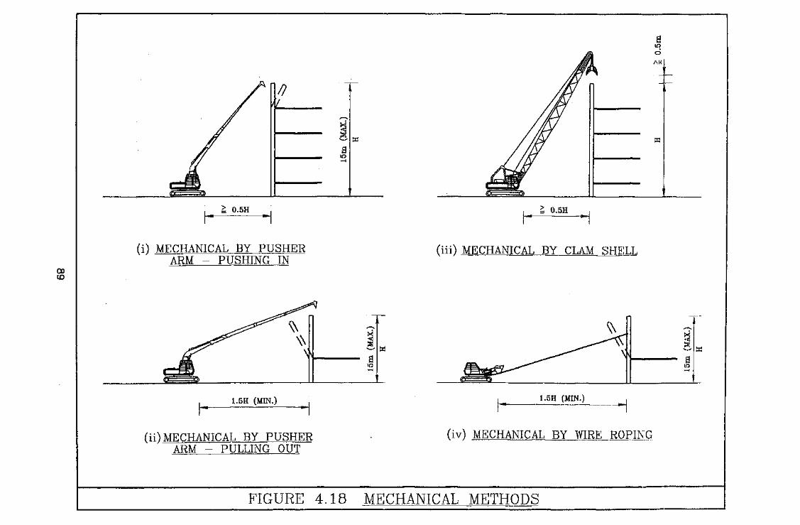
5 0.5H ^ 0.5H
COID
(i) MECHANICAL BY PUSHERARM - PUSHING IN
(iii) MECHANICAL BY CLAM SHELL
1.5H (MIN.)
(ii) MECHANICAL BY PUSHERARM - PULLING OUT
1.5H (MIN.)
(iv) MECHANICAL BY WIRE ROPING
FIGURE 4.18 MECHANICAL METHODS
(4) The site shall have fidl time security to preventunauthorized personnel entering the site. No person shallstay within the working area of the machine and thebuilding while the machine is operating;
(5) Sufficient water spray or other anti-dust precautions shallbe provided to minimise air pollution by dust;
(6) The cab of the machine shall be equipped with impactproofed glass and its construction shall be robust enough toprotect the operator from flying debris;
(7) A spot person shall be on site full time to provide guidanceand assistance to the operator in the demolition process.
In addition to the above, specific criteria for each mechanicalmethod are discussed in the following sections:
(B) Mechanical by pusher arm
Mechanical pusher arm involves the use of machines equippedwith a pusher arm attachment for applying horizontal thrust todemolish the structural element. Special conditions for pusher armdemolition are listed below:
(1) The pusher arm shall be constructed of steel or equivalentmaterial and shall have adequate strength to operate on thebuilding; a crane boom shall not be used;
(2) Minimum safety distance of 0.5 times the height of thebuilding element being demolished shall be maintainedbetween the machine and the building for pushing into thebuilding;
(3) Minimum safety distance of 1.5 times the height of thebuilding element being demolished shall be maintained ifstructural elements are pulling out of the building;
(4) The point of pushing Application shall not be less than 2/3of the height and not more than 600 mm below the top ofthe wall;
(5) The pusher arm method shall be limited to buildings lessthan 15m high.
90

(C) Mechanical by deliberate collapse
Mechanical demolition by deliberate collapse generally consists ofsystematic removal, or weakening of the key structural elements toinduce the collapse of the structure. Special conditions fordeliberate collapse are as follows:
(1) Minimum safety distance of 1.5 times the height of buildingelement being demolished shall be maintained throughoutthe operation;
(2) The procedures shall be carefully designed and executed inthe removal of key structural elements so that there will beno pre-mature collapse and the structure will collapse ontothe anticipated area;
(3) Application of the deliberate collapse method shall belimited to buildings less than 15 m high.
(D) Mechanical by wire rope pulling
Mechanical demolition by wire rope pulling generally involves theuse of an earth mover machine or mechanical winch deviceequipped with heavy steel wire for pulling down structuralmembers. Special conditions for wire rope pulling are listed in thefollowing:
(1) A safety distance of 1.5 times the height of element to bedemolished shall be maintained between the machine andthe building during the pulling;
(2) The machine shall always travel parallel to the line of pullduring the pulling operation;
(3) In the case when pulling is done by a pulley, such a pulleydevice shall be securely anchored;
(4) The wire rope or chain shall be composed of steel withtensile strength not less than 4 times the theoretical forcerequired to perform the pulling;
(5) The wire rope used for the operation shall be inspected forwear and damage at least twice daily and replaced asnecessary;
91
(6) Any sharp edge that is to be wound by the rope shall beprotected to minimise the possibility of cutting or wearingof the rope during pulling;
(7) The bottom of the wall may be pre-weakened with care andprotection to ensure controlled collapse;
(8) The wire rope pulling shall be limited to buildings less than15 m high;
(9) All workers shall stay away from the area within reach ofthe rope or wire in case it breaks.
(E) Mechanical by clam shell
Demolition by clam shell typically involves the use of a craneequipped with a clam shell attachment which progressively bitesaway the structure. Special conditions for clam shell are listed inthe following:
(1) A minimum safety distance of 0.5 times the height of thebuilding element being demolished shall be maintainedbetween the machine and the building during the operation;
(2) The process of biting off the structural elements shall beginfrom the top and progress downwards;
(3) The clam shell shall be operated not less than 1 m above thestructure being demolished.
4.6.5 Thermal Lance
Cutting of reinforced concrete by thermal lance involves very hightemperature up to 2,000 - 4,000°C. The extremely high heat requiresspecial precautionary measures and care. The use of a thermal lance incutting reinforced concrete shall not be used unless;
(A) the project demonstrated that there is no other viable alternative;
(B) adequate protective measures are provided to isolate the operationand to prevent any potential fire spreading out;
(C) adequate protective measures are provided to prevent the injury ofthe workers, and any third party by flame and the molten concrete.
92

4.6.6 Water jet
Water jetting involves the use of a water jet stream pumped at highpressure to erode the cement matrix and wash out the aggregates.Abrasive compounds may be added for cutting reinforcing steel. Theapplication of the water jetting shall be subject to the following criteria:
(A) City water supply shall be used in water jet cutting. Provisionshall be included to dispose the water used in the operation, and torecycle the water for continuous operation through local filtrationand sedimentation;
(B) The area behind the structural member to be cut shall be shieldedto avoid damage to persons and properties during the cutting;
(C) In the case when abrasive water jets are used, furtherprecautionary measures shall be provided in accordance withmanufacturer recommendations to confine the rebound of theabrasive compounds. All site personnel shall wear adequate safetycover and clothing.
93

5,
5.1 Precast Concrete Structures
5.1.1 General
Precast concrete structures are constructed of precast concrete elementsjoined together. The continuity of the structure depends on thetreatment of joints. The joint details shall be studied. In case of doubt,open up inspection at critical positions may be required.
5.1.2 Simple Precast Construction
The joints in this type of structure do not normally provide continuity.The stability of this type of structure relies on other elements such asstairs, lift shafts, shear walls or other framed structures.
(A) Dismantling
Each precast element shall be removed in the reverse order ofconstruction and broken on the ground or an adequately supportedfloor. Elements providing lateral stability shall not be demolishedprior to the removal of the precast elements or prior to theinstallation of the temporary bracing. Temporary supports shall beadequately braced or tied to laterally stable elements.
(B) Existing Lifting Points
The re-use of the existing lifting points or accessories to lift theprecast elements shall not be allowed unless the record erectionplans showing the function of the existing lifting points arechecked and verified to be adequate for current use.
(C) Lateral Support During Lifting
Special consideration shall be given to long span precast elementswith narrow compression flanges during lifting. Spreader beamsshall be used to reduce the spacing of the lifting points. The use ofspreader beam is illustrated in Figure 5.1,
94
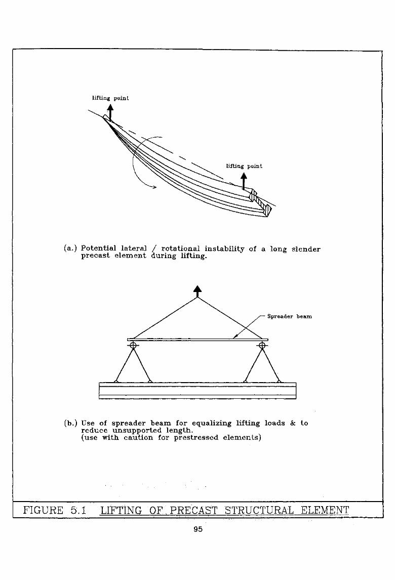
lifting point
lifting point
(a.) Potential lateral / rotational instability of a long slenderprecast element during lifting.
Spreader "beana
(b,) Use of spreader beam for equalizing lifting loads & toreduce unsupported length.,
".(use-;with caution for prestressed elements)
FIGURE 5.1 LIFTING OF PRECAST STRUCTURAL ELEMENT
95
5.1.3 Precast Construction
In this type of structure, the precast elements have continuity at theirjoints and the lateral stability is provided by the precast elementsthemselves. The continuous precast elements may be in the form ofshear walls or moment resisting frames. It is possible that acombination of the simple construction and continuous constructionexist in a single structure.
(A) Dismantling
The demolition of this type of structure may be performed in a waysimilar to that of a cast-in-place concrete construction providedthat the continuous joints are cut in such a way that the lateralstability is maintained. If the precast elements are intended to beremoved in a piece by piece manner in their reverse order ofconstruction, the continuous joint shall be cut by appropriate pre-approved method such as saw cutting. The precast elements shallthen be lifted off their support and lowered to the ground or to anadequately supported floor for demolition. Temporary bracingduring lifting as described in 5.1.2(C) may be required.
5.2 Prestressed Concrete Structures
5,2*1 General
The prestressed concrete structures are constructed of either precast orcast-in-place concrete in which prestressing is introduced to theconcrete by tensioning the steel reinforcement, or tendon, to counteracta desired degree of stress resulting from a given external loading. Thetypes of prestressing and guidelines for identification are discussed inAppendix C.
5.2.2 Classification of Prestressed Concrete Structures
Based on the construction technique, the prestressed concreteconstruction can be classified into three major classes. Depending onthe method of stress transfer, i.e., pre-tensioning or post-tensioning, andwhether it is grouted, each class of construction can be furthersubdivided into separate categories as follows:
(A) Class I: Precast Prestressed Construction:
Category PI Precast pre-tensioned
CategoryP2 Precast pre-tensioned/post-tensioned
96

Category P3 Precast post-tensioned
(B) Class II: Cast-in-Place Prestressed Construction
Category Cl Post-tensioned before applicationof dead and, live load and havingall tendon ducts folly grouted.
Category C2 As 'Category Cl but having thetendon ducts ungrouted.
Category C3 Post-tensioned is in stages as theload earned by the member isincreased in stages as theconstruction progress. The tendonducts are fully grouted in the finalcondition. Transfer beamsupporting multi-level frames is anexample of this category.
Category C4 As Category C3 but having thetendon ducts ungrouted.
(C) Class III: Others
(1) Segmental Post-Tensioned Construction
The segmental post-tensioned structuresinvolve the construction of the mainstructural elements in segments. Their finalintegrity is achieved through post-tensioningof tendons which pass through and tie thesegments together.
(2) Circumferential Prestressed Tanks
The tanks are prestressed by tendons bondedin grouted ducts or by unbonded tendons.
5.2.3 Precautionary Site Measures
(A) Detensioning
Due to the high energy stored in the prestressed members, thedemolition of such members must be proceeded within a plannedsequence and well controlled manner. During detensioning of the
97

tendons, a protective screen made of sand bags or similar materialsuch as a backed plywood screen shall be placed at the anchorends. The protection screen is illustrated in Figure 5.2.
(B) Shoring and Site Safety
The prestressed concrete floor system shall be properly shoredprior to detensioning to prevent the collapse of the system. Therelease of energy during the demolition of prestressed concretecould be extremely hazardous. All workers on site must beinformed of the presence of prestressing in the structure and thehazardous result on deviating from the prescribed procedures. Apre-determined safety plan shall be in place.
(C) Grout
For a structure with bonded construction, the conditions of thegrout shall be checked. If the tendons are not fully grouted,additional grout shall be applied to fully fill the ungrouted voids.After grouting, the prestressed structure may be demolishedsimilar to that of a bonded construction.
5.2.4 Demolition Procedures
The following procedures for each class and category of prestressedconcrete shall only be used as a guideline. Detailed procedures shall beindependently developed for each structure by an engineer experiencedin prestressed construction based on the design, layout of the tendons,sequence of the stressing and construction.
(A) Class I: Precast Prestressed Structures
(1) Category PI: Precast Pre-Tensioned Structures
Precast pre-tensioned structures are typically single spanelements and must generally be demolished in the reverseorder of construction.
98

I 200-300mm
Prestressed slab/bea.
Plywood screen
Support platform
(a.) Plywood protective screen
Timber supportadequately nailedto screen & support
Prestressed slab/bear
*'
0mm
End anchor-
Sand bags
Support platform
(b.) Sand bag screen
FIGURE 5.2 PROTECTION FOR DETENSIONING OF PRESTRESSEDCONCRETE TENDONS
99

The precast pre-tensioned elements can be lifted off andturned on their sides, after the connections at the supports areremoved. The lifting points shall be located near the ends ofthe units and shall be adequately designed to ensure safelifting of the precast elements with these elements turned onto their side. The above process will generally fracture thestructure and causing a sudden release of .energy. After theenergy is released, the can be cut or pulverisedinto pieces before they are hauled away.
If turning the elements on their sides does not release theenergy, a sand bag or other suitable screen shall be providedaround the ends. The prestressed energy can be released byappropriate means such as the one described In5.2.6(B)(2)(c).
(2) Category P2: Precast Pre-Tensioned/Post-TensionedStructures
Sometimes two or more pieces of precast prestressedelements are continuously connected together at the supportsby post-tensioning. This post-tensioning shall bedetensioned according to the recommendations fordemolition of post-tensioned structures In Class IIconstruction as described in the 5.2.6(B). After the post-tension energy is released the remaining precast prestressedelements may be demolished in accordance with theprocedures for Category PI elements.
(3) Category P3: Precast Post-Tensioned Structures
These precast elements shall be lifted off from their supportand placed on their side if the prestressed tendons are ofgrouted construction. If the conduits are not fully grouted,the elements shall be placed level on the ground and thepost-tensioning forces shall be released in accordance withthe procedures for Category C2 elements as described in5.2.6(B)(2).
Adequate protection must be provided at the ends of theelements in case the tendons shoot out at the ends. In general,cutting of unbonded tendons at mid-span will dampen theshoot off effect
100
(B) Class II: Cast-in-Place Prestressed Structures
(1) Category Cl: Post-Tensioned Grouted
These elements shall be demolished as precast elements. Fora single span slab, the slab may be saw cut into segments andlifted off similarly to precast elements. For continuousspans, the prestress over the support shall be released prior tocutting the slab into segments. It must be noted thatprestressing may be provided in two directions and thedetailed procedures shall take this into account. For beamand slab, caution shall be exercised to avoid upward failureof the beam when the slab is removed. When detensioning oftendons is involved, all slab and beam spans shall betemporarily supported to prevent unintentional collapse ofthe structure.
(2) Category C2: Post-Tensioned Ungrouted
The demolition of these elements shall generally proceed asfollows:
(a) Shore up all slab and beam spans for whichdetensioning of tendons is required.
(b) Remove all superimposed dead load.
(c) The prestressing forces can.be released by cutting awaythe concrete in front of the anchorage until theanchorage has been loosened. Alternatively, the forcesmay be released by saw cutting at appropriate locationsalong the tendons. During the detensioning, the ends ofthe tendons shall be protected from shooting off.
(d) The structure can be demolished as normal reinforcedconcrete.
(3) Category C3: Post-Tensioned in Stages and Fully Grouted
Care shall be exercised to avoid premature failure of theelements when the dead load superimposed on the elementsis reduced as demolition progresses. The load which isearned by the element must be supported by temporarystructures extended above the element. After the temporarysupports are constructed, the elements may then bedemolished by the following steps:
101
(a) Locate and the centrelines of the columnssupported by the member;
(b) Locate the profile of the tendons and mark it on bothfaces of the member;
(c) Expose the exterior tendons on each face of the membermidway between the centrelines of all intermediatecolumns supported by the member;
(d) Cut the exposed tendons at each location starting fromthe centre of the member on alternating faces andproceed to the ends of the member;
(e) Repeat steps (c) and (d) until all the tendons have beencompletely severed.
Demolition using the above procedures shall be exercisedwith caution to prevent the tendons from pulling together thecolumns at the ends of the elements due to the elasticshortening at the exposed tendons.
(4) Category C4: Post-Tensioned in Stages but Ungrouted
Care shall be exercised to avoid premature failure of theelements when the dead load superimposed on the elementsis reduced as demolition progresses. Temporary structuresshall be provided to shore up the elements as needed. Theprestressed force shall be-detensioned sequentially in reverseorder of stressing in accordance with the amount of dead loadremoved. The sequence of the detensioning shall preferablybe in the reverse order of the tensioning when the elementwas constructed. When all supporting dead load and tendonsare removed, the element can be demolished in the samemanner as for normal reinforced concrete.
Alternatively, demolition may proceed in the same manner asfor Category C3.
(C) Class III: Others
(1) The demolition of segmental construction shall proceed in thereverse order of the segmental erection. Temporary supportsshall be provided as required before the post-tensioning forcesare released. Where the segmental units are pre-tensioned,demolition shall proceed as for precast pre-tensioned/post-tensioned construction. Where the units are not pre-tensioned,demolition shall proceed in the same manner as for post-tensioned construction.
102
(2) During detensloning of the prestressed cables or tendons in acircumferential prestressed tank, appropriate protectivemeasures, such as adequately designed protective chain nets,screens or friction brakes shall be provided to avoiduncontrolled unwinding of tendons.
(3) The demolition of segmental construction, or ckcumferentialprestressed tanks is relatively complex and it must bedemolished under the guidance of a professional engineerexperienced in this type of construction.
5.3 Statically Determinate Structures
5.3.1 General
(A) Statically determinate structures normally lack continuity, whichhas the following characteristics :
(1) large deflection; and
(2) high stress concentration at critical position.
The disadvantage is that if any part of the structural system fails, itcan cause a disastrous collapse of the structure.
(B) Special attention is required where dealing with demolition orpartial demolition of the following structures:
(1) statically determinate structures;
(2) redundancy structures that may become staticallydeterminate structures during demolition or aftersubstantial alteration.
(C) Common statically determinate structures include the following:
(1) cantilever structures,
(2) hinged or pin-jointed trusses.
103
5.3.2 Cantilever Structures
(A) In general, cantilever structures shall be demolished prior todemolition of the main structure of the building;
(B) In the case when 5.3.2(A) cannot be satisfied, the cantileverstructures shall be properly shored until it is completelydemolished;
(C) Common problems of cantilever structures are described in Figure5.3.
5.3,3 Hinged or pin-jointed trusses
(A) Under normal circumstances, hinged or pin-jointed structures arebraced structures. Temporary supports shall be provided ifbracings are removed;
(B) Hinged or pin-jointed trasses shall preferably be removed bylifting and lowering to ground level prior to demolition;
(C) In the case when the trass has to be dismantled on the spot, thesequence of every partially dismantled configuration shall bechecked.
5.4 Composite Structures and Steel Structures
5.4.1 General
Steel structures and reinforced concrete composite structures are, inmost cases, designed as "simple design" or "seim-rigid design"according to earlier structural steel design codes. Under such designassumptions, the detailing of the beam column joints is, in most cases,not rigid joints and the structure may become statically determinateduring demolition or substantial alteration. Details of demolition ofstatically determinate structures are referred to in 5.3.
5.4.2 Demolition Method
Similar to conventional buildings, composite structures may bedemolished by top down method, cut and lift or other methods that areadequate for the site condition.
104
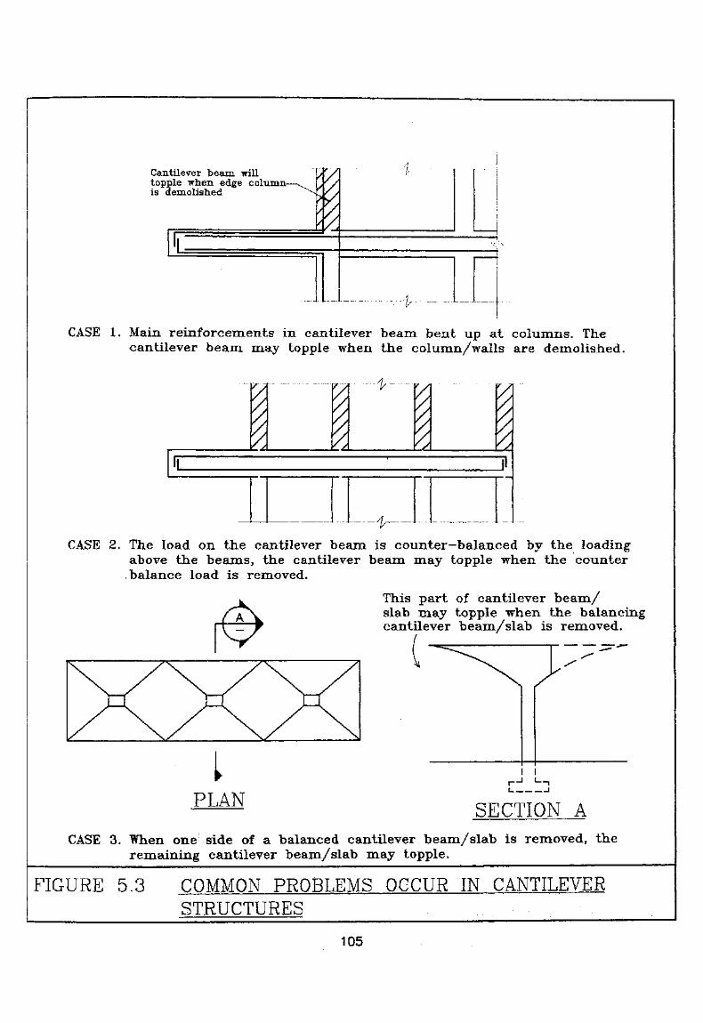
Cantilever beam willtopple when edge column-is demolished
CASE 1. Main reinforcements in cantilever beam bent up at columns. Thecantilever beam may topple when the column/walls are demolished.
III I 'lr- ~
//„
I \I'
CASE 2. The load on the cantilever beam is counter-balanced by the loadingabove the beams, the cantilever beam may topple when the counterbalance load is removed.
This part of cantilever beam/slab may topple when the balancingcantilever beam/slab is removed.
I 1
PLAN SECTION A
CASE 3. When one side of a balanced cantilever beam/slab is removed, theremaining cantilever beam/slab may topple.
FIGURE 5.3 COMMON PROBLEMSSTRUCTURES
OCCUR IN CANTILEVER
105

5.4.3 of
Structural steel members in steel structures and reinforced concretecomposite structures are generally designed as slender members subjectto bending and/or compression. Except for concrete encased steelmembers the Registered Structural Engineer shall check the loadresisting capacity of the slender structural members when lateralrestraints are removed during demolition. Proper shoring shall beinstalled if required.
5.5
5.5.1 Demolition Method
Demolition of cladding walls shall be proceeded with extreme cautionsince cladding walls are mostly external features. Each cladding wallshall be demolished individually in the reverse order of its construction.Saw cut and lift is suitable for dismantling cladding walls.
5*5*2 Guidelines
(A) Support
The cladding wall shall be fully supported before disconnectionfrom its supporting structural member. Crane or other liftingappliances may be used to support the total weight of the cladding.The lifting appliances and wire must have sufficient strength tosupport the weight of the cladding wall.
(B) Disconnecting from Building
The connections or joints to the building structure shall bedisconnected only after the cladding wall is fully supported.
(C) Handling
Once the cladding wall is separated from the building frame, itmay be lifted away and lowered onto the ground or adequatelysupported floor for further processing. Depending on the type ofcladding, it may be reused as building materials or further brokendown and transported away as construction debris.
106
5,6
5.6.1
The hanging structure Is primarily composed of a structural system inwhich the floor loading is suspended by tension members hung fromother elements at the upper portion of the structure. Unlikeconventional structures, hanging structures shall be demolished fromtheir bottom level and progressively upward to the support.
5.6.2 Demolition Method
Selection of methods shall depend on the actual site conditions and theconstruction materials. Cutting and lifting, in general, are suitable fordismantling the structural components of the hanging structure.Temporary supports may be needed to maintain the stability of thehanging structural elements during the demolition process.
5.6.3 GuidelinesThe following items shall be considered in demolishing hangingstructures:
(A) The sequence of demolition shall be planned such that the hangingloads are gradually reduced, without overstressing at anyparticular structural element or ties;
(B) Hanging ties shall be destressed before cutting;
(C) Main gravity structures supporting the hanging ties and otherelements that provide lateral stability of the hanging structure shallnot be demolished prior to complete release of all hanging ties;
(D) The main gravity structure shall be checked so that it Is stable at allstages of demolition, bracing may be required if deemednecessary.
5.7 Oil Storage Facilities
5.7.1 General
Oil storage facilities generally consist of structures that containpetroleum products which may be classified as hazardous materials ordangerous goods The key issues for demolishing the oil storagefacilities are the clean-up and disposal of the hazardous materials anddangerous goods. Once the contamination assessment aad initial
107

clean-up are completed, the method of demolition may be selectedbased on the structural and site conditions. Additional clean up may berequired if the contamination has extended to the adjacent area and/orthe subsurface soil. Precautionary measures and work systems to beadopted for working in such an environment shall comply with theFactories & Industrial Undertakings (Confined Spaces) Regulations.
5.7.2 Demolition Methods
The selection of methods and actual demolition of oil storage structuresshall be carried out in accordance with the structural aspects. Storagebuildings may be demolished by top down method or other methods forbuilding demolition. Circular steel tanks may be dismantled by the useof hydraulic shear or other appropriate methods. Reinforced concretetanks may be dismantled by any method that is suitable for reinforcedconcrete construction. If flammable fuel is likely to be present, use offlame cutting shall be avoided. Methods of demolition are referred to inSection 4.
5.7.3 Guidelines
The following items shall be considered in demolishing oil storagefacilities:
(A) Chemical Waste Clean Up
Prior to demolition, all oil storage facilities shall be thoroughlycleaned. Any accumulated gas shall be removed. The managementof waste and wastewater generated from the process must conformwith the Waste Disposal Ordinance and the Water PollutionControl Ordinance. Additionally, the management of any wastewhich is classifiable as a chemical waste, such as oil sludge fromtank cleaning must also comply with the Waste DisposalOrdinance (Chemical Waste) (General) Regulation. In the casewhen a dangerous goods storage licence has been issued, therelevant licensing authority, i.e. Fire Services Department, or GasStandard Office, shall be informed prior to any demolitionoperation. Any risk of fire explosion and exposure to toxicity shallbe minimised.
(B) Soil Contamination Assessment
After completion of demolition, Soil Contamination Assessment(SCA) shall be carried out according to the SCA and Clean-upproposal agreed by the EPD. In the case when soil contaminationis discovered, the contaminated soil shall be removed in its entiretyand replaced with clean fills. The placement of the fill shall be
108

under the supervision of the Authorized Person or RegisteredStructural Engineer or an equivalent professional The disposal ofcontaminated soil shall be carried out in strict accordance with theEPD requirements. In-situ treatment of the contaminant may beapplied subject to the approval of the EPD.
(C) Handling of Contaminated Soil
Precautions must be taken during excavation and removal of thestorage tank. The excavation and disposal of contaminated soilshall be handled with care and be in compliance with the EPDrequirements. Special care shall be taken to confine thecontamination. Protection of the surrounding properties to providea safe support for any below ground works shall be considered.Temporary shoring for the excavation shall be designed inaccordance with 3.5.
5.8 Marine Structures
5.8.1 General
Marine structures include ocean structures and all kinds of water frontstructures. Besides the basic considerations for normal land operation,marine demolition shall also attend to the debris handling and thedismantling of the marine piles.
5.8.2 Method of Demolition
The methods used for demolishing marine structures are similar to thosefor buildings founded on land. Top down methods may be applied todemolish the superstructure. Non-explosive demolition agent may beused to demolished the piers. For sensitive water, saw cut and lift canbe used to demolish the platform and the piers to miiiiinise debris fallinginto water.
5.8.3 Guidelines
(A) Soundings
Soundings shall be performed before the demolition so that theseabed condition is defined and any unanticipated underwaterstructure can be reviewed. The pre-demolition sounding recordshall be used as a basis for the scope of restoration.
109
(B) Pier Structure
If mechanical plants and/or trucks will travel on the platformsupported by piers, the structure of the platform slab bechecked to ensure that it can support the machine operation and theanticipated debris loading.
(C) Protection of Marine Environment
The effect of the demolition on the marine environment shall beconsidered. If the demolition site is scheduled to be reclaimed,concrete debris may be left on the seabed. Otherwise, all thedebris dropped on the seabed during demolition must be removed.The seabed shall be restored to the comparable depth of the pre-demolition stage. A silt screen or underwater fence shallencompass the site to contain debris and turbulence generated bythe demolition. It may also prevent marine life from entering thesite area during demolition. The silt screen shall be taken out afterthe area is completely restored.
(D) Piling
As far as practical, piling shall be pulled out entirely, or, as aminimum, it shall be cut off at 3m below the seabed or a desirabledepth below the original seabed level, depending on the future useof the area.
5.9 Underground Structures
5.9.1 General
From the operational and economic standpoints, demolition ofunderground structure shall be incorporated into the new foundationconstruction. Such arrangement may eliminate the redundancy of thetemporary works for soil retention and dewatering systems.
5.9.2 Demolition Method
With appropriate shoring and protection, underground structures abovethe basement floor may be demolished by top down methods or othermethods that are suitable for the specific site conditions. The use ofnon-explosive demolition agents may minimise vibration impact on theadjacent foundation. Diamond core stitch drilling is suitable for cuttinglocalised underground obstructions such as an old pile cap withoutcompletely demolishing the whole pile cap.
110

5.9.3 Guidelines
(A) Shoring
A geoteckoicat evaluation shall be conducted to determine the soilstabilisation and retaining schemes, for protection of the adjacentproperties as well as the operation of the below ground demolition.The shoring plan shall be taken into account of the constructionmethod to the original underground structure. If the floors or partof the building structure acts as plopping to the basement wall, thispropping system shall be maintained or a shoring system shall beprovided to safely support the basement wall when demolishingthe building structure.
(B) Uplift Pressure
In high water table areas, assessment shall be made to ensure thatthe remaining structure will have adequate factor of safety againstuplift upon demolition at all stages. If necessary, the upliftpressure acting on the basement structure shall be relieved beforedemolishing the structure.
(C) Dewatering
If a dewatering system is required, the effect of the dewatering onadjacent foundations must be considered in the design. It is alsoimportant that the disposal of the ground water shall not affect thequality of the surrounding water resource and/or cause localisedflooding.
(D) Existing Foundation
The existing piles shall be evaluated and, if possible, incorporatedinto the new foundation system. The bearing capacity of the oldfoundation can be determined by reviewing the previous designand by performing actual load tests and/or test borings.
(E) Site Security and Safety
The site shall be secured to prevent any unauthorized person fromentry, particularly into the basement area. If work is to beperformed in deep excavated area, an escape route must beprovided.
I l l

5.10 or on
5,10.1
Demolition of buildings supporting sloping ground or buildings sittingon slopes or retaining walls may affect the stability of adjacentstructures and land and may -even* create regional slope instability dueto removal of toe weight. Maintaining adequate ground support bybackfilling or structural support during demolition work is important.The demolition plan should be properly engineered by a competent andexperienced geotechnical engineer.
5.10.2Demolition Method
Top down method is suitable for demolition of hillside slope structures.Other methods may be applicable depending on the actual siteconditions.
5.103 Guidelines
•(A) Buttress/Shoring for Building Supporting Ground
If part of the building structure serves as a retaining wall system,the height of the building that is required to be left in order tosafely support the retaining structure shall be determined.Adequate shoring and/or buttress shall be provided prior to thedemolition of the remaining structure. A demolition plan shall beprovided to the foundation contractor so that the shoring workinstalled during demolition are considered and protected duringthe foundation work.
(B) Retaining Wall System
Prior to demolition of the retaining wall, the slope or earthsupported by the retaining wall system must first be stabilised.Stabilisation may be achieved by excavation of the soil behind theretaining wall to a free standing stable slope or by installingtemporary or permanent support such as sheet piling, soldier pileor other appropriate methods. The scheme for stabilisation of theslope behind the retaining wall shall be properly engineered.
112
(C) On-grade Floor Slab
Unless site conditions allow and the support of anengineering report, the on-grade floor remain to protectagainst erosion. The floor slabs can also serve as impermeablecover against infiltration.
(D) Surcharge on Slope and Retaining Wall
No storage of debris or surcharge shall be imposed on the area onthe top of the retaining wall and/or slope. Surcharge on the top ofthe retaining wall and/or slope may affect its stability.
(E) Drainage
The water table may affect the stability of the slope. Drainagefrom surface runoff, off site drainage and infiltration shall beconsidered and managed throughout the project.
113
6. SITE SUPERVISION AND INSPECTION
6.1 General
Demolition consists of operational processes in dismantling structures in asequential order that is documented in a method statement. Demolition workcan be carried out safely when the sequence of demolition work is followedand each demolition process is properly executed. To achieve this end, propersupervision of the demolition work and adequate training of on site personnelare essential.
A site supervision plan shall be prepared in accordance with the TechnicalMemorandum for Supervision Plans and the Code of Practice for Site SafetySupervision of Building Works and Street Works.
114

Appendix ADemolition Checklist
A
1.
1.1 Site Location
D Identify site location, neighbouring conditions, adjoiningbuildings, slopes, and retaining walls.
O Identify special site restrictions such as the designatedscheduled areas, specific restrictions on the time ofoperation, limitation on the noise and vibration etc.
D Identify impact on special buildings adjacent to the sitewhich may be affected by the demolition project such ashospitals and other occupancies that are sensitive to noise,vibration and dust or other nuisance produced by thedemolition.
1.2 Project Site and Building Structures to be Demolished
D Identify the building/structures to be demolished.
D Verify dimensions of site, building set backs, availableworking spaces etc.
D Identify hoarding/covered walkway requirements.
D Verify the dimensions of buildings, such as overall buildingheight, headroom of floors, and building footprint.
D Verify the building construction, types of material used inconstruction of the building, construction method, illegalconstruction, special structural features that need specialtreatment during demolition such as cantilever structures,precast structures and prestressed structures etc.
D Verify the existing fixtures: any features which may affectthe demolition progress and need to be removed prior todemolition of the structure, such as water tanks, airconditioning units and other mechanical services.
Al

Appendix ADemolition Checklist
D Verify the building use: the type of occupancy, the historyof building use and any illegal use.
1.3 Utilities Location
D Verification of all below ground and overhead utilities.
D Termination and disconnection of any services to thebuilding to be demolished in accordance with therequirements of the utility companies.
D Arrangement of temporary utilities for the project use, suchas water supplies for dust suppression, etc.
1.4 Demolition Schedule
D Identify factors that may affect the demolition schedulessuch as any operational restrictions imposed by regulationsand anticipated seasonal weather conditions.
D Develop a realistic schedule which will reflect the timerequired for installation of precautionary measures, testingand removal of hazardous materials, if any, processing ofapproval and consent, demolition process, clean up and siterestoration.
1.5 Testing and removal of hazardous materials
D Arrange investigation for asbestos containing materials by aregistered asbestos consultant.
D If asbestos abatement work is required, submit an AsbestosInvestigation Report and Asbestos Abatement Plan andnotification of commencement of asbestos work to EPDand Labour Department.
1.6 Safety Measures
D The requirements of covered walkway and catch platformfor pedestrian protection.
D The requirement of catchfan, if necessary.
A2
Appendix ADemolition Checklist
D The requirement of double layer scaffolding, screens andworking platforms for retaining dust and flying debris if the
used and site conditions warrant.
D The safety procedures for operation. Adequateground or floor support for the machine; and the installationof temporary proppings.
D Temporary supports and bracing for any weakenedstructures.
D Protection of vehicular and pedestrian adjacent tosite.
D Supports for adjacent retaining wall and/or slopes.
1.7
D Sorting and removal of non-structural materials such astimber, doors and windows etc. and disposal to recyclingfacilities or landfill.
D Adequate number and size of chutes depending on the rateof debris generation, and the disposal route.
D Planning of traffic route for debris handling, includingprovision of lorry car parks,
1.8 Preparation of Demolition Plan (details refer to Appendix B)
1.9 Stability Report with Calculations
D Stability of building to be demolished.
D In the case of powered mechanical plants or requirements areused, stability of the building.
D Shoring to support powered mechanical plants.
D Effect on neighbourhood building, adjoining properties, and partywalls caused by the demolition.
O Structural or geotechnical calculation to support adjoiningproperties.
A3

Appendix ADemolition Checklist
1.10
D Submit Supervision Plan
D Submit names and details of Technically Competent Persons.
D Submit details of particular of plant operators.
2.
D All on site precautionary measures and temporary supportsfor adjacent properties are .installed according to the designin the method statement.
D Removal of hazardous materials, if any, are completedbefore the demolition. Chemical wastes such as oily sludgefrom oil tank cleaning, asbestos waste, unwanted toxicchemicals are managed in compliance with the WasteDisposal (Chemical Waste) (General) Regulation.
O All site personnel are fully informed about the specifics ofthe projects and the necessary precautionary measures to betaken to ensure safety.
D Establish emergency access.
D Establish clear and operational line of communication tothe supervisor.
D The demolition to be progressed in conforaiance with themethod statement and/or with the approval of the AP andRSE.
D Removal of debris to avoid accumulation, considering thetraffic condition and availability of tracks.
D Control the dust emission in compliance with Air PollutionControl (Construction Dust) Regulation,
D Adequate supervision by full time competent supervisor onsite, periodic visit by representatives of the AP and RSE,and Ml time supervision by engineer for special structuresas required.
A4

Appendix ADemolition Checklist
O Protection of adjoining party wall the demolition.
D Ensure all workers follow safety procedures and themachines and equipment are well maintained.
D Provide security for the site as appropriate.
D Schedule regular inspection and maintenance ofscaffolding, and special inspection after typhoon or fireaccident.
3, After
D The site shall be clear of debris and levelled.
U The boundaries shall be secured against unlawful entry.
D Excavations, if any, shall be protected.
D For sloping site and/or site with retaining wall the followingitems shall be included.
Ground surface shall be sealed to prevent waterinfiltration.
Surface drainage shall be provided.
Demolition plan shall be provided to the foundationcontractor so that temporary supports constructed duringdemolition can be maintained.
A5

Appendix BDemolition Plan Checklist
B
All the information and data collected during the pre-deniolition survey shall beused as input for choosing the method for the demolition project. Although thedemolition method shall be efficient and cost effective, however, in developing theDemolition Plan, the author shall always have public safety and site safety in mind.Each project has its unique features and conditions. Demolition Plan shall becustomised to meet the conditions of the individual project. One of the purposes ofthe Demolition Plan is to provide instructions and guidelines for the on sitepersonnel to follow so that the works can be performed safely and effectively.Therefore, when developing the Demolition Plan, it has to bear in mind that theDemolition Plan shall be straight forward, easy to follow and understood bypersonnel at various levels of education. Typically, the Demolition Plan shallinclude, but not limited to, the following information:
1. Location Plan
A scaled plan showing the following information:
D The scale of the plan shall be in according to B(A)R13.
D Location of the project building with respect to lot boundary,adjacent footpath and traffic way.
D Location and relative heights of existing utilities, adjoining buildingsand properties and their use.
O The plan shall be fully dimensioned with elevations shown.
2. Existing Building Information
The Plan showing the project building and site conditions shall include thefollowing:
D An assessment on the conditions of the building, site and adjacentproperties including their historical and existing use and trafficconditions of the abutting roads.
Bl

Appendix BDemolition Plan Checklist
D Any that protection and may during theprogram such as environmental or historical features,
slope protective features, special features such as flyoverand footbridges and such as overhead cables etc.
D Proposed arrangement for the removal of hazardous materials and/orwastes if they are present.
3. The of the and
A structural plan shall include the following:
D The overall height of the building, the ceiling height of the floors,dimensions and depth of the basements, if any.
D Structural plans and sections, details and layouts of the structuralsupports and the construction materials, if available.
D Structural evaluation of the adjacent buildings and shared featuresas party wall, staircases and common supporting structures.
D Information on any special structures that require special attention,such as cantilever structures, prestressed concrete, precast concrete,steel composite structures, cladding walls, stressed skin structures,hanging structures etc.
4. Procedure and Sequence of Operation
The Plan showing the proposed method used to demolish the structure shallinclude the following:
D Descriptions of the equipment to be used.
D Specific guidelines on the limitations of the machine's operationsuch as travel area, specific distance from the building line and anyarea with inadequate support or limited headroom,
D The sequence and proposed procedures for the demolition.
D Detail instructions for demolishing special features and critical areasthat may impact on the general safety of the public and on sitepersonnel.
D Specific precautionary steps for identifying these features.
B2
Appendix BDemolition Plan Checklist
5.
Specification, construction details for precautionary measures whichare essential to the project safety. The type of precautionary features shallbe selected to best meet the requirements of the demolition method and thesite conditions. The following features shall be included wherever it isnecessary:
D Covered walkways, catch platforms and hoardings :
D Scaffolding and catchfans.
D Temporary supporting systems to support machines working on thebuilding floors.
D Temporary supports for cantilever structures and for bracingweakened structural elements.
D Detailed design for temporary support and protection of anystructure that may be affected by the demolition, such as party walls,or any attached structures, whether they are legal or not.
D Inspection and maintenance frequency for the precautionarymeasures.
D Support for adjacent retaining walls or slopes that may be affectedby the demolition.
6,
D A proposed plan for conveyance of debris, on site sorting andmanagement, estimated amount of debris required for off sitetransportation.
7. Special Safety Considerations
D Means of emergency escape, and access route.
D Means to reduce the dust, noise and vibration impacts.
D Storage and handling of any flammable material that may be used inthe demolition process.
D Proper packaging, labelling and storage of asbestos waste generatedin the demolition process.
B3
Appendix BDemolition Plan Checklist
8,
D If the project Involves any temporary closure of traffic, a TrafficImpact Assessment with detail locations of the temporary trafficsigns shall be provided.
9, Post-Demolition Arrangement
D Permanent treatment to party walls and stabilisation of adjacentstructures.
D Site security
D Stabilisation of excavation, if any.
D For sloping sites or sites with retaining walls, additionalarrangements for sealing off ground surface, provide adequatedrainage and stabilisation of the slopes and/or retaining structures.
10, Chinese Version
D A properly translated Chinese Version of the Demolition Plan shallbe provided.
B4
Appendix CPrestressed Concrete andGuidelines for Identification
C
FORIDENTIFICATION
1. of
(A) Pre-tensioning
Pre-tensioning is a prestressing process in which the tendons or cables aretensioned prior to the casting of concrete. The prestressing is then transferred tothe hardened concrete by bonding. This type of process is commonly used inconstruction of precast elements including structural and non-structural, such asprecast concrete cladding. Normally, the tendons are placed in one direction ofthe element along its longitudinal axis.
(B) Post-tensioning
Post-tensioning is a prestressing process in which the tendons or cables, encasedin sheathing or ducts, are placed without tensioning prior to casting of concrete.When the concrete attains an acceptable specified strength, the tendons will betensioned by jacking at the ends of the member through the anchors. After thetensioning is done, the sheathing will be either grouted with cementitious groutor left ungrouted. In the former case, the construction is known as bondedconstruction. In the latter case, it is the unbonded construction. In the case of theunbonded construction, the sheathing is normally filled with grease. Theprestressing tendons may be placed in two directions in particular for slabconstruction.
2. Guidelines for Identification of Prestressing Structures
2.1 Record Drawing
Prior to the demolition of a building, a full investigation must take place todetermine if any prestressed construction exists in the structure. This can beobtained through review of the record drawings of the buildings or through siteobservation if the record drawings are not available. If record drawings areavailable, information should be obtained on the structural design, on the methodand sequence of the tensioning, and on whether the tendons are bonded orunbonded.
2.2 Characteristics of Prestressed Concrete
If record drawings are not available, the following provides some minimumguidelines for identifying 'the potential existence of prestressed construction.
Cl
Appendix CPrestressed Concrete andGuidelines for Identification
(A) Review the existing floor system and the type of construction. It could bean indication of possible use of post-tensioning construction for a one-way or two-way slab with a exceeding 8 metres, for a joist systemexceeding 11 metres and for a system 15 metres.
(B) In addition to the above guidelines, the shown in TableC-l could be used as a for judgement.
(C) Large span beams supporting multi-storey columns above them may be anindication of being post-tensioned.
(D) If long span precast concrete construction is found, it is normally quiteeasily identified, as jointing between precast quite often are visiblewith even soffit level. The units may be prestressed.
(E) Check the edges of the slab, along the perimeter of the building, along theinside face of stairwells, elevator shafts, duct shafts, etc. for signs ofpost-tensioned anchorage or any signs of burned off tendon ends.
(F) Check the ends of beams for any patches of regular shapes which couldindicate the existence of prestressed tendons,
(G) During the course of demolition, if any concrete elements exhibit anunusually high degree of resilience upon impacting with demolition tools,this could be an indication that the member is prestressed.
When prestressing is suspected without any record drawings, furtherinvestigation shall be performed to identify the layout and construction of thesystem. A discovery of one post-tensioned floor in a structure does notnecessarily prove that all floors are post-tensioned and vice versa.
C2
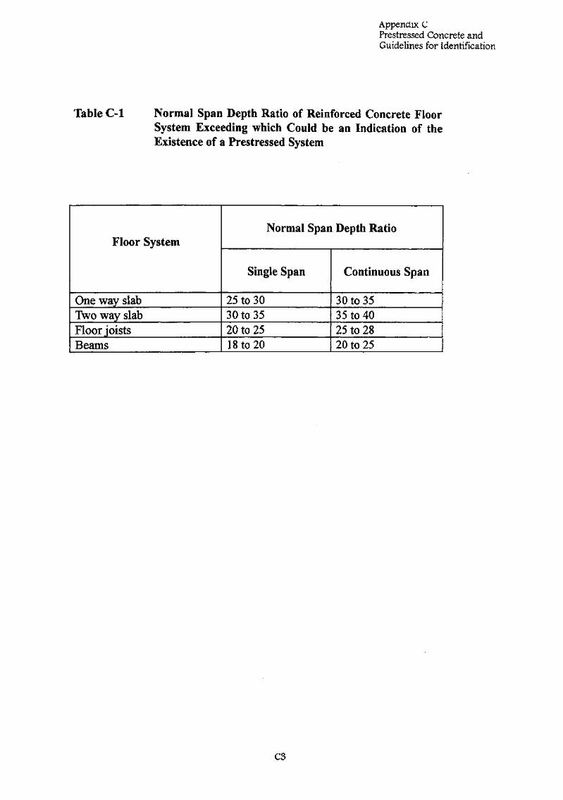
Appendix CPrestressed Concrete andGuidelines for Identification
C-l Normal of Concrete FloorSystem be an of theExistence of a Prestressed System
Floor System
One way slabTwo way slabFloor joistsBeams
Normal Span Depth Ratio
Single Span
25 to 3030 to 3520 to 2518 to 20
Continuous Span
30 to 3535 to 4025 to 2820 to 25
C3
Appendix DRegulations Relating to Demolition Projects
D
TO
1. Building demolition is subject to the following legislation andsubsidiary documents administered by the Building Authority:
(i) The Buildings Ordinance, Laws of Hong Kong SpecialAdministrative Region, CAP 123,
(ii) The Building (Administration) Regulations,
(iii) The Building (Construction) Regulations,
(iv) The Building (Demolition Works) Regulations,
(v) The Building (Planning) Regulations,
(vi) Practice Note for Authorised Persons and Registered StructuralEngineers 71, Demolition Works - Measures for Public Safety,
(vii) Practice Note for Authorised Persons and Registered StructuralEngineers 75, Hoarding, Covered Walkways and gantries(Including Temporary Access for Construction Traffic) - Building(Planning) Regulations Part IX,
(viii) Practice Note for Authorised Person and Registered StructuralEngineer 175, Antiquities and Monuments - Antiquities andMonuments.
(ix) Practice Note for Registered Conrtractors 4, Hoarding, Walkwaysand Contractors Sheds - Building (Planning) Regulations Part IX,
(x) Practice Note for Registered Contractors 6, Demolition Works,
(xi) Technical Memorandum for Supervision Plans.
2. Building demolition is subject to the following legislation andsubsidiary documents administered by the Environmental ProtectionDepartment:
(i) Air Pollution Control Ordinance,
(ii) Air Pollution Control (Construction Dust) Regulation,
(iii) Noise Control Ordinance, and relevant technical Memoranda,
(iv) Waste Disposal (Charges for Disposal of Waste) Regulation,
(v) Waste Disposal (Chemical Waste)(General) Regulation,
Dl
Appendix DRegulations Relating to Demolition Projects
(vi) Water Pollution Control Ordinance,
(vii) Waste Disposal Ordinance,
(viii)Code of Practice on the Packaging, Labelikg and Storage ofChemical Waste,
(ix) Code of Practice on the Handling, Transportation and Disposal ofAsbestos Waste.
3* Building demolition is subject to the following legislation andsubsidiary documents administered by the Labour Department:
(i) Factories and Industrial Undertakings Ordinance,
(ii) Factories and Industrial Undertakings Regulations,
(iii) Factories and Industrial Undertakings (Confined Spaces)Regulations,
(iv) Factories and Industrial Undertakings (Lifting Appliances andLifting gear) Regulations,
(v) Factories and Industrial Undertakings (Fire Precaution inNotifiable Workspaces) Regulations,
(vi) Factories and Industrial Undertakings (Protection of Eyes)Regulations,
(vii) Factories and Industrial Undertakings (Electricity) Regulations,
(viii) Factories and Industrial Undertakings (First Aid in NotifiableWorkplaces) Regulations,
(ix) Factories and Industrial Undertakings (Dangerous Substances)Regulations,
(x) Factories and Industrial Undertakings (Safety officers and SafetySupervisors) Regulations,
(xi) Factories and Industrial Undertakings (Noise at Work)Regulations,
(xii) Construction Sites (Safety) Regulations,
(xiii) Factories and Industrial Undertaking (Asbestos) Regulations,
D2
Appendix DRegulations Relating to Demolition Projects
(xiv)Code of Practice for Scaffolding Safety,
(xv) Safety Guidelines for Demolition of Building Structures.
4. In the design of hoarding, covered walkways, temporary works, andpossible modifications of the existing building structure, the followingdocuments are relevant:
(i) Building (Planning) Regulations provide general requirements onhoarding, covered walkways and contractor sheds,
(ii) Building (Construction) Regulations provide general requirementson construction including hoarding requirements,
(iii) Building (Demolition Works) Regulations provide precautionrequirements,
(iv) Code of Practice on Structural Use of Concrete (1987) (ConcreteCode 1987),
(v) Code of Practice on Structural Use of steel (1987) (Steel Code1987),
(vi) Code of Practice on Wind Effects in Hong Kong (1983) (WindCode 1983).
(vii) Code of Practice for Site Safety Supervision on Building Worksand Street Works.
5. Design of temporary supports to stabilise the slopes and grounds duringthe demolition of retaining structures, basements and othergeotechnical features shall refer to:
(i) Geotechnical Manual for Slopes,
(ii) Guide to Retaining Wall Design, Geoguide L
6. Other Ordinances and Regulations:
(i) Dangerous Goods Ordinance,
(ii) Gas Safety (Registration of Gas Installers and Gas Contractors)Regulations,
(iii) Code of Practice on Avoiding Danger from Gas Pipes.
D3
Appendix ENotifications and Statutory Procedures
E
AND
1.
If asbestos abatement work is to be carried out in a building to bedemolished, the owner of the premises must submit both an AsbestosInvestigation Report and Asbestos Abatement Plan and a written noticeof the date of commencement of asbestos abatement work to the EPD28 days before the asbestos abatement work commences.
Factories and Industrial Undertakings (Asbestos) Special Regulationsrequire the contractor to give a written notice to the Commissioner forLabour not less than 28 days before he begins an asbestos process.Before carrying out any work which may expose any worker to asbestosan adequate assessment of the likely exposure shall be made by acompetent person, in accordance with the Factories and IndustrialUndertaking (Asbestos) Special Regulations. The Contractor shall alsoobserve the aforesaid regulations and take appropriate preventivemeasures to prevent asbestos exposure and to protect the health of theworkers engaged in the removal work.
2.
Prior to the demolition of the building structure, a hoarding permit shallbe obtained from the Buildings Department for the installation ofhoarding, covered walkways and any other temporary supportingstructures outside the lot boundary. The hoarding permit would beissued after the review and approval of the Hoarding Plan submitted bytheAPandRSE.
3. Excavation Permit
If the hoarding, covered walkway or any of the demolition relatedinstallation is to be installed on the public land, an Excavation Permitshall be required from the Highways Department. If required, theExcavation Permit shall be obtained before the installation of anyprecautionary measures.
El
Appendix ENotifications and Statutory Procedures
4. for the
A Demolition Plan together with a Stability Report includingcalculations be submitted to the Department forapproval. Upon approval of the Demolition Plan, the AuthorisedPerson shall submit a specified form applying for consent fordemolition, together with(i) a site safety supervision plan,
. (ii) the names of Technically Competent Persons and their particulars,and
(iii) the details of powered mechanical plant operators;and the Buildings Department will consider issuance of the Consent forthe Demolition Work. Demolition may begin once the consent fordemolition work is obtained. Prior to commencement of demolitionwork, the Authorised Person shall inform the Building Authority theappointment of a Registered Specialist Demolition Contractor using thespecified Form BA10; and the Registered Specialist DemolitionContractor shall inform the public the appointment of a TechnicallyCompetent Person by posting the specified Form BA20 on the externalfacade of the site.
5* Notification for Commencement
Under the Air Pollution Controls (Construction Dust) Regulation, theprincipal contractor shall give notice to the EPD in a specified form withthe specified particulars before the demolition work commences. Ifthere is any proposed change to any of the particulars given in aprevious notice, the principal contractor shall also notify the EPD beforethe proposed change take effect.
6. Posting of Information
Prior to the commencement of demolition work, the RegisteredSpecialist Demolition Contractor shall post the following informationon the hoarding:
(A) the Hoarding Permit,
(B) the Excavation Permit,
(C) the Consent for Demolition,
(D) Form BA20 informing the Competent and Experienced SiteSupervisor in charge of the demolition work,
(E) the contact telephone number of
E2
Appendix ENotifications and Statutory Procedures
- the Authorised Person,
- the Registered Structural Engineer,
- the person-k-charge of the Registered Specialist DemolitionContractor.
- Experienced and competent person'in charge of the demolitionsite.
7* Activities the "Restricted Hours"
• No works involving the use of Powered Mechanical Equipment and/orSpecified Powered Mechanical Equipment within restricted hoursshould be allowed without a valid Construction Noise Permit (CNP)issued by the EPD. The requirement shall be referred to the TechnicalMemorandum-on Noise from Construction Work in Designated Areas.The restricted hours are defined as all day during 1900 to 0700 hoursand general holidays, including Sunday, during 0700 to 1900 hours. Theapplication of such a CNP has to be submitted to the Authority at least28 days before the proposed commencement of any works to allow forthe processing of the application. A CNP will be cancelled immediatelyif a breach against any of the conditions is found.
8. Discharge to the Waters of Hong Kong
If the work involves making a new discharge into the water of HongKong, application for a licence will be required under the WaterPollution Control Ordinance. The applicant should notify the public bypublishing the application in an English and a Chinese Newspaper at hisown expenses. The Director of Environment Protection Departmentmay grant a licence to the applicant not earlier than 40 days after thepublishing of the notice and if no objection is received.
9. Notification for Completion
Upon completion of the demolition and the necessary required post-demolition works, the Buildings Department shall be notified inspecified form for inspection and acceptance of the work. BuildingsDepartment will acknowledge the acceptance of the specified foim uponsatisfactory completion of the project.
10. Debris Disposal
The disposal requirements of construction demolition waste at variouslandfills are listed in the following:
E3
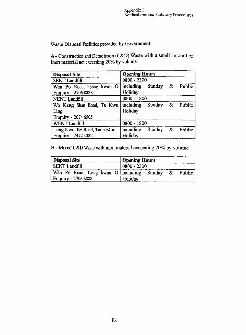
Appendix ENotifications and Statutory Procedures
Waste Disposal Facilities provided by Government:
A- Construction and Demolition (C&D) Waste with a small amount ofinert not exceeding 20% by volume.
Disposal SiteSENT LandfillWan Po Road, Tseng kwan OEnquiry - 2706 8888NENT LandfillWo Keng Shan Road, Ta KwuLingEnquiry - 2674 6505WENT LandfillLung Kwu Tan Road, Tuen MunEnquiry - 2472 4382
Opening Hours0800-2300including Sunday &Holiday
Public
0800 - 1800including Sunday &Holiday
Public
0800 - 1800including Sunday &Holiday
Public
B - Mixed C&D Waste with inert material exceeding 20% by volume
Disposal SiteSENT LandfillWan Po Road, Tseng kwan 0Enquiry - 2706 8888
Opening Hours0800 - 2300including Sunday &Holiday
Public
E4

Appendix F
F
OFTOP
1.
1.1 The demolition shall consist of the following
1.1.1 Fig F1 Site Plan and Adjoining Site Conditions.
1.1.2 Fig F2 Typical Floor Plan and Existing Building Information.
1.1.3 FigF3 Elevation A.
1.1.4 Fig F4 Demolition procedure and sequence.
1.1.5 Fig F5 Precautionary Measures.
1.1.6 Fig F6 Typical Support at Cantilever.
1.1.7 Fig F7 Typical detail for Party Wall Strengthening.
1.2 In the case of sloping ground, the following additional plans are required :
1.2.1 Plan showing adjoining slopes, buildings, structures, utilities that maybe affected by the demolition.
1.2.2 Sections Showing the slopes etc.
1.2.3 Supports to slopes, buildings etc. at each stage of demolition.
2 STABILITY REPORT
2,1 The Stability Report of this project shall consist of the following :
2.1.1 A Stability report to justify the safety of the existing building during allphases of demolition.
2.1.2 A structural check with calculation on the support of the cantilever slabbetween guidelines A and B.
2.1.3 A structural check with calculation on the hoarding, covered walkwayand catch platform.
Fl
Appendix F
2.1.4 A structural check with calculation on the strengthening of the PartyWall
2.2 In the case of a site, the thefollowing :-
2.2.1 Stability check of the adjoining slopes, buildings, structures and utilitywhich may be affected by the demolition, with supporting calculations.
2.2.2 Optional Structural and Geotechnical checks on any remedial measuresto strengthen the slope.
F2

Appendix F
mPD = m Principal Datura
16m
5.55rnPD
6.60mPD
63«HCO
*,1,5m llm"7T SERVICE LANE
u
9 11
6.50mPD—— —^=—• water
services6.55mPD
A STREETtelephone —«<""lines \
S, 6.48mPD
2 4 6 8 10 12 14 1C
SITE LOCATION PLAN (SCAUE i:soo)
FIGURE F.l. SITE PLAN AND ADJOINING SITE CONDITIONS
- 1, A STREET (SHEET 1 OF 2) „____F3

Appendix F
GENERAL NOTES:i.The building to be demolished is No. 1, A street. Detailed information of this building is
shown on Fig. FS and F3.2. General information of No, 1, A street are as follows :
2.1 The site is outside all scheduled area,2.2 Site area : llin x 12m2.3 Boundary conditions:
North : A 2 m wide service land separated the project building from the adjacentbuilding,
East : The project building Is directly adjoining an adjacent building at No. 3S Astreet,
South : The building abuts A street,West : The building abuts; B street,
2.4 Topography : Flat, no slope or .retaining wall within the vicinity of the site,2.5 Traffic conditions : Moderate traffic on both A street and B street,2.6 No antiques, historical monument or special feature required protections.
3. Adjacent'utilities which may be affectedley demolition :3.1 There are no above ground cable or wire.3.2 There are water services, underground telephone and electric services along A street \
and B street The closest utility services Is'about 4 m from the building line. Therefore,the demolition of the building will not affect these underground utilities. !
4. Adjacent buildings : i4.1 Structural and general information :
The structure at No, 3, A street adjoins the project building is also built in the 1960.It is a 4-storey high reinforced concrete building with conventional frames, slabs andpile foundation,.
4.2 Conditions :The building appears to be in good structural condition with no major cracks orstructure deterioration. Except for the party wall, the demolition process should nothave any significant impact on the structure at the adjacent building.
4.3 Party wall and common features :(A) Party wall :
(1) There is a 4-storey high party wall between the premises and the building atNo. 39 A street,
(li) The party wall is of brick construction. The thickness of the wall Is 450 mm(IB") at the ground floor and 350 mm (1.4") at 1 st floor and above,
(lii) Party wall between the premises and No. 3, A street will require strengtheningduring the demolition process.
(B) Common features :There are no other elements such as shared staircases, unauthorised building,overhead cables or wires shared services thai would be affected by the proposeddemolition.
FIGURE F.I. SITEJILA^^
- 1, A STREET (SHEET 2 OF 2) __F4

Appendix F
A; ^B1.5m nT" 3.5m
I
1
©
4 K -
LEGEND :i > , , A cantilever balconies, propping\///\ with 20kN at 1.2m centre shall
be provided on ALL floors
D3.5m
/> /\ ' /\/ ' /' /
/ / / /'' / / /
I/ / /" ',''
IV / / /
YS ' /I/ / / /
/ / / /
y////'///-'
/ ,'' r-*-7^7 f--T — ?H,
/ r ''
i-— r
:
J L
S-B1
r1
1
S-B3
3 JT" """""— L
S-B3
i r
••
staircases foremergency use
4i 1
S-C2
3 _ . . , . .. r~
\
flooropeningsfor chiit<
S
•4i \i—
S-C3
\ f1
siteboundary • ,
1L
u^\a ••
5-D2
r^-I•f L~r
S-D3
i r1
adjoining/ party wa
adjoiningbuilding
•JL-,!_J
\ F3 /
FIGURE F.2. TYPICAL. FLOOR-PLAN AND EXISTING BUILDINGINFORMATION - 1, A STREET (SHEET 1 OF.2) .
F5

Appendix F
NOTES ON EXISTING BUILDING:1. General information and dimensions
1.1 Age : 30 years (built in i960)1.2 Use : Residential1.3 Building cover area : 12.5m x 12m1.4- Building height : 23.5ms 8 storeys1.5 Floor height : Ground floor is 3.8 m with a 2.2 m mezzanine; 1 st floor and
above are 3.5 m.
2. Structural conditions2.1 Structure :
The structure consists of reinforced concrete frames with conventional column, beamsand slabs. Both exterior and interior walls have in-fill bricks. The building is foundedon a pile foundation.
2.2 Conditions :The building is currently vacant and has been maintained in a satisfactory condition.Based on our site inspection, the building shows no sign of any significant structuraldamage or deterioration Only minor cracks to the non-structural brick walls wereobserved.
3. Special structural features3.1 The building consists of cantilever slabs and beams along the frontage of A street.
No other special structure as listed in section 2.1.3(a)6 in the Code of Practice forDemolition of Buildings were found.
4. Hazardous materials :4.1 An Asbestos Investigation Report (AIR) will be conducted by a registered asbestos
consultant. If asbestos containing material is found to be inside the building, anAsbextos Abatement Plan (AAP) will be submitted to the" Environmental ProtectionDepartment 28 days before the asbestos abatement work commences. The asbestosabatement works shall be performed in accordance with the Air Pollution ControlOrdinance and the Factoried and the Factories and Industrial Undertaking (asbestos)Regulations. The AIR and AAP will be submitted to the EPD directly.
FIGURE F.2. TYPICAL FLOOR PLAN AND EXISTING BUILDINGINFORMATION - 1, A STREET (SHEET 2 OF 2)
F6
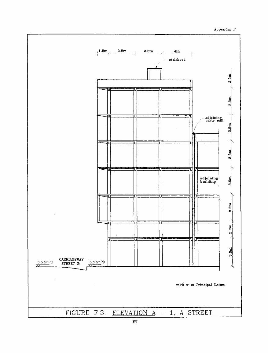
Appendix F
.,1.5m,,- - I " A
3,5m , , 3,5m
stairliood
CARRIAGEWAY6.53mPD STREET B
_-.-..._
6.53mPD
J
J
LI
J
LI
U
J
; i
1
l |
I
1 S
1 1
1 1
n
i
i S
I S
I 1
1 !
1 I
1 1
i I
..- adjoininparty vj
/
! i
r
JT
J
J
J
adjoiningbuilding
1
sID«*!
mPB = m Principal Datum
FIGURE F.3. ELEVATION A — 1, A STREETF7
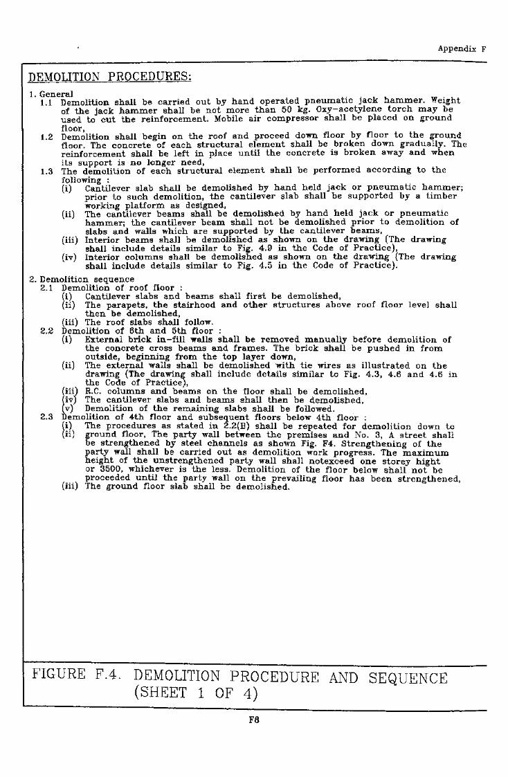
Appendix F
DEMOLITION PROCEDURES:1. General _ ,
1.1 Demolition shall be carried out by hand operated pneumatic jack hammer. Weightof the jack hammer shall be not more than 50 kg. Oxy-acetylene torch may beused to cut the reinforcement. Mobile air compressor shall be placed on groundfloor,
1.2 Demolition shall begin on the roof and proceed down floor by floor to the groundfloor. The concrete of each structural element shall be broken down gradually. Thereinforcement shall be left in place until the concrete is broken away and whenits support is no longer need,
1.3 The demolition of each structural element shall be performed according to thefollowing :(i) Cantilever slab shall be demolished by hand held jack or pneumatic hammer;
prior to such demolition, the cantilever slab shall be supported by a timberworking platform as designed,
(ii) The cantilever beams shall be demolished by hand held jack or pneumatichammer; the cantilever beam shall not be demolished prior to demolition ofslabs and walls which are supported by the cantilever beams,
(iii) Interior beams shall be demolished as shown on the drawing (The drawingshall include details similar to Fig. 4.9 in the Code of Practice),
(iv) Interior columns shall be demolished as shown on the drawing (The drawingshall include details similar to Fig. 4,5 in the Code of Practice).
2. Demolition sequence2.1 Demolition of roof floor :
(i) Cantilever slabs and beams shall first be demolished,(ii) The parapets, the stairhood and other structures above roof floor level shall
then be demolished,(iii) The roof slabs shall follow.
2.2 Demolition of 6th and 5th floor ;(i) External brick in-fill walls shall be removed manually before demolition of
the concrete cross beams and frames. The brick shall be pushed in fromoutside, beginning from the top layer down,
(ii) The external walls shall be demolished with tie wires as illustrated on thedrawing (The drawing shall include details similar to Fig. 4.3, 4.6 and 4.6 inthe Code of Practice),
Iii) R.C. columns and beams on the floor shall be demolished,iv) The cantilever slabs and beams shall then be demolished,v) Demolition of the remaining slabs shall be followed.
2.3 Demolition of 4th floor and subsequent floors below 4th floor :fi) The procedures as stated in 2.2(B) shall be repeated for demolition down to(ii) ' ground floor, The party wall between the premises and No. 3S A street shall
be strengthened by steel channels as shown Fig. F4. Strengthening of theparty wall shall be carried out as demolition work progress. The maximumheight of the unstrengthened party wall shall notexceed one storey hightor 3500, whichever is the less. Demolition, of the floor below shall not beproceeded until the party wall on the prevailing floor has been strengthened,
(iii) The ground floor slab shall be demolished.
FIGURE F.4. DEMOLITION PROCEDURE AND SEQUENCE(SHEET 1 OF 4)
F8
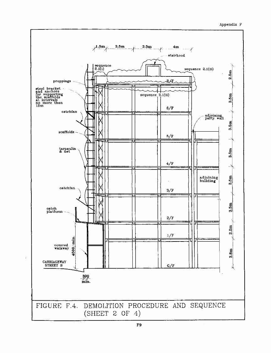
Appendix F
3.5m 3.5m y 4m .,•1 " " A
proppmgs
steel bracketand anchorsfor supportingthe scaffoldsat intervalsno more than15m
catchfan
scaffolds — ,.
tarpaulin • ,& net \
catchfan
catchplatform
coveredwalkway o
CARRIAGEWAYSTREET B
'min.
-stairhood
sequence 2.1(ii)
, adjoining;/'" party wall
FIGURE FA. DEMOLITION PROCEDURE AND SEQUENCE(SHEET 2 OF 4)
F9
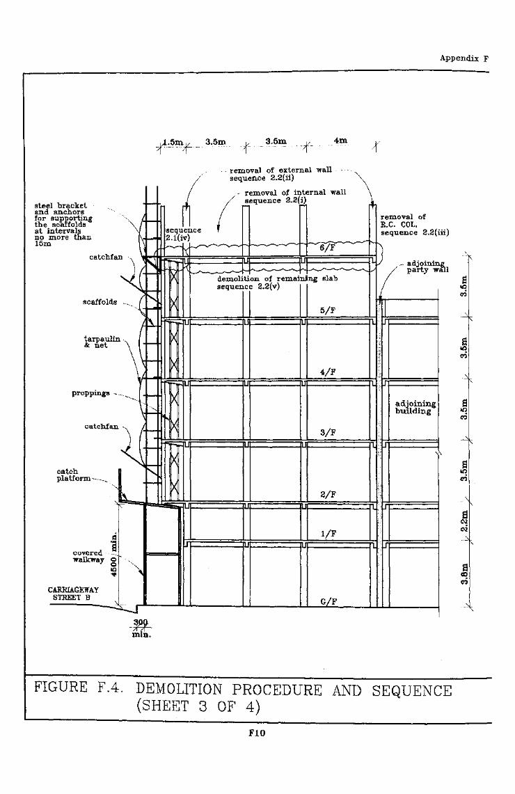
Appendix F
3.5m 4m
steel bracketand anchorsfor supportingthe scaffoldsat intervalsno more than15m
removal of external wallsequence 2.2(ii)
removal of internal wallsequence
catchfan
scaffolds -
tarpaulin& net
proppings -
catchplatform
removal ofE.G. COL,sequence 2.2(iii)
- adjoining;party wall
demolition of remaining slabsequence 2.2(v)
a**
s00
FIGURE F.4. DEMOLITION PROCEDURE AND SEQUENCE(SHEET 3 OF 4)
F10
Appendix F
tarpaulin& net
scaffolds
proppmgs
catch,platform ,
,A-5m,/ 3,5m v 3.5m L/T" " " "'T " " A
4m
strengtheningof party wallsequence 2.3(ii)
.- adjoining' party wall
remoyal of internal brickwallsequence 2.3(i)
removal of R.C. COL.beam, sequence 2.2(iii)
removal of external wallsequence 2.3(i)sequence
2.3(1)
sequence 2.3(i) adjoiningbuilding
walkway o
CAEEIAGEWAYSTEEET B
FIGURE F.4. DEMOLITION PROCEDURE AND SEQUENCE(SHEET 4 OF 4)
Fll

Appendix F
scaffolding, protective — -•screen, safety net
covered walkwaycatch platform
; HOARDING PLAN ;(DETAILS OF HOARDING, COVERED WALKWAY,CATCH PLATFORM SIMILAR TO FIG. 3.2, 3.3SHALL BE SHOWN ON THIS DRAWING)
FIGURE F.5. PRECAUTIONARY MEASURES
(SHEET 1 OF 4)F12
Appendix F
proppings
steel bracket • • • • • . .and anchorsfor supportingthe scaffolds \at intervalsno more than15m
catchfan s
4scaffolds ^
catchfanlcatch 1platform- ,,., |
_d iwalkway "g " -x
to s^
CARE1AGEWAYSTKEET B
/
j;y\v
\AJ
^/1i
a
\
\
mmjm •
-mm
\
X-uitip n
^
^;
aast
,.L5m.. 3,5m ,, 3.5m ( . 4mr :;t ' ;f 't f
stairhead
4\X
X
X
X""-I
X
X"—I
X
X•*-!
X
Xt :
- u
- U
:u
- U
:u
;u
j
n
I I
I I
U
I F
i 1
1 1
R/F}
i
L
I
"""" "" I
!
1
J L
6/F
S „ , L
5/F1 ' 5
4/Fi i
3/FI """ • " 1
2/Fi i
l/F1 - , l
G/F
adjoinii/' party w
j
i
adjoiningbuilding
I\
i
i
300mih.
FIGURE F.5. ELEVATION A
(SHEET 2 OF
a&nCQ
aID
iff&
1CO
aiO00
a00
a06
1
aCD
CO
N
\
- PRECAUTIONARY MEASURES
4)F13
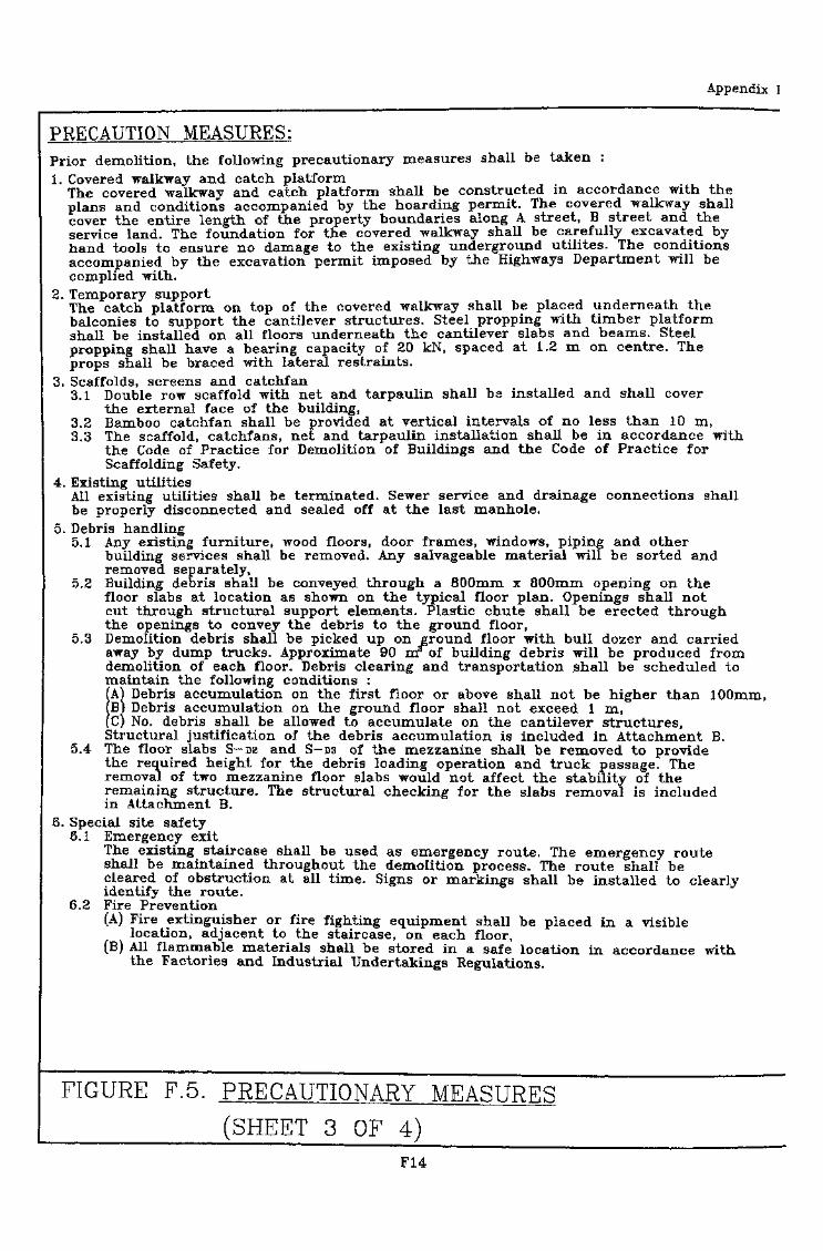
Appendix I
PRECAUTION MEASURES:Prior demolition, the following precautionary measures shall be taken :1. Covered walkway and catch platform
The covered walkway and catch platform shall be constructed in accordance with theplans and conditions accompanied by the hoarding permit. The covered walkway shallcover the entire length of the property boundaries along A street, B street and theservice land. The foundation for the covered walkway shall be carefully excavated byhand tools to ensure no damage to the existing underground utilites. The conditionsaccompanied by the excavation permit imposed by the Highways Department will becomplied with.
2. Temporary supportThe catch platform on top of the covered walkway shall be placed, underneath thebalconies to support the cantilever structures. Steel propping with timber platformshall be installed on all floors underneath the cantilever slabs and beams. Steelpropping shall have a bearing capacity of 20 kN, spaced at 1.2 m on centre. Theprops shall be braced with lateral restraints.
3. Scaffolds, screens and catchfaii3.1 Double row scaffold with net and tarpaulin shall be installed and shall cover
the external face of the building,3.2 Bamboo catchfan shall be provided at vertical, intervals of no less than 10 m,3.3 The scaffold, catchfans, net and tarpaulin installation shall be in accordance with
the Code of Practice for Demolition of Buildings and the Code of Practice forScaffolding Safety.
4. Existing utilitiesAll existing utilities shall be terminated. Sewer service and drainage connections shallbe properly disconnected and sealed off at the last manhole.
5. Debris handling5.1 Any existing furniture, wood floors, door frames, windows, piping and other
building services shall be removed. Any salvageable material will be sorted andremoved separately,
5.2 Building debris shall be conveyed through a 800mm x 800mm opening on thefloor slabs at location as shown on the typical floor plan. Openings shall notcut through structural support elements. Plastic chute shall be erected throughthe openings to convey the debris to the ground floor,
5.3 Demolition debris shall be picked up on ground floor with bull dozer and carriedaway by dump trucks. Approximate 90 nr of building debris will be produced fromdemolition of each floor. Debris clearing and transportation shall be scheduled tomaintain the following conditions :A) Debris accumulation on the first floor or above shall not be higher than lOQmm,B) Debris accumulation on the ground floor shall not exceed 1 m,C; No. debris shall be allowed to accumulate on the cantilever structures,
Structural justification of the debris accumulation is included in Attachment B.5.4 The floor slabs S-B2 and S-DS of the mezzanine shall be removed to provide
the required height for the debris loading operation and truck passage. Theremoval of two mezzanine floor slabs would not affect the stability of theremaining structure. The structural checking for the slabs removal is includedin Attachment B. :
8. Special site safety6.1 Emergency exit
The existing staircase shall be used as emergency route, The emergency routeshall be maintained throughout the demolition process. The route shall becleared of obstruction' at all time. Signs or markings shall be installed to clearlyidentify the route.
8.2 Fire Prevention(A) Fire extinguisher or fire fighting equipment shall be placed in a visible
location, adjacent to the staircase, on each floor,(B) All flammable materials shall be stored in a safe location in accordance with
the Factories and Industrial Undertakings Regulations.
FIGURE F.5. PRECAUTIONARY MEASURES
(SHEET 3 OF 4)F14

Appendix F
PRECAUTION MEASURES:6.3 Dust and noise
(A) Water spraying shall be applied to suppress the dust generated during thedemolition operation and debris hauling,
(B) Super silenced type air compressor shall be used. Demolition works shall notbe performed within the restricted hours from. 1900 hrs. to 0700 hrs. all dayand from 0700 firs, to 1900 hrs. on general holidays including SUNDAY.
8.4 TrainingAll site personnel shall go through a training programme to understand the projectand site safety requirements. The training programme shall be conducted by acompetent trainer. The training programme shall include the following :(A) An Induction course at the beginning of the job to circulate information on
the proposed method and required safety measures to perform to perform thework,
(B) Daily safety meetings to maintain and reinforce the safety concept.6.5 Typhoon
In the case when Typhoon Signal No. 3 is hoisted, the Contractor shall inspectall scaffolding, protective screen, and externally exposed temporary work andstrengthen any losse connections. After the typhoon, all scaffoldings, protectivescreens and externally exposed temporary works shall be inspected and confirmedto be safe by the competent and experienced person.
7. Maintenance and inspection7.1 All the precautionary measures, covered walkway, catch platforms, catchfans and
temporary supports shall be inspected by the AP and RSE on a weekly basis andthe contractor on a daily basis. Any accumulation of building debris on thecatchfans and catch platforms shall be removed. Any deficiency shall be repairedwhen found necessary. The inspection and repair records shall be provided to theAP and RSE.
7.2 Before leaving the job site each day, the contractor shall indentify and rectifyany unsafe conditions such as partially demolished structural elements anddamaged temporary supports.
7.3 The scaffolding shall be inspected and maintained In accordance with the Codeof Practice for Scaffolding Safety and the Construction Site (Safety) Regulationsby the contractor.
8. Emergency plan8.1 Emergency telephone numbers shall be clersaly displayed in a conspicuous location.
In the event of any emergency or accident, the contractor shall notify the Policeand Fire service Departments for assistance. The contractor shall also notify theAP and RSE immediately.
8.2 At the initial warning of a typhoon or a major storm event, the following shallbe performed :8.2.1 Contractor shall secure all scaffold, screen, temporary supports and loose
elements on site. The scaffold shall be taken down to the prevailing toplevel of the building,
8.2.2 All flammable materials, oxygen and acetylene bottles shall be removed orsecured in a safe location.
8.2.3 No unstable and/or partially demolished structural elements shall be lefton site. If this is unavoidable, the unstable structure shall be braced andsecured.
9. Post demolition9.1 Upon completion of the demolition, the site shall be levelled and cleared of debris.9.2 In the case of no immediate redevelopment, the site boundary shall be completely
enlcosed to prevent public access.9.3 Arrangement shall be made for permanent treatment of the party wall.9.4 Damage to pavement, footpath and other elements within the right of way shall be
repaired to its original condition prior to the completion of the demolition project.
FIGURE F.5. PRECAUTIONARY MEASURES
(SHEET 4 OF 4)F15
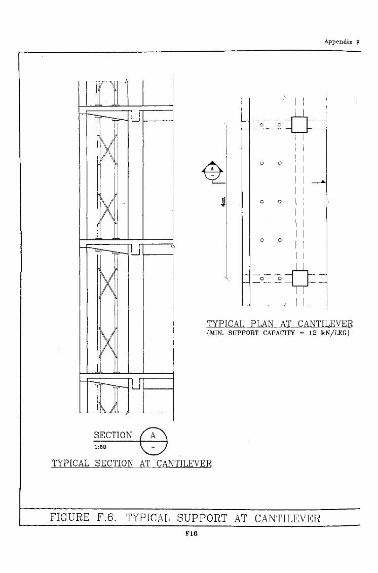
Appendix F
U
u
U
SECTION1:50
o o
o o
o o
o o
o o
TYPICAL PLAN AT CANTILEVER(MIN. SUPPORT CAPACITY = 12 kN/LEG)
TYPICAL SECTION AT CANTILEVER
FIGURE F.6. TYPICAL SUPPORT AT CANTILEVERF16
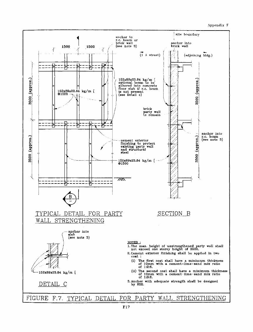
Appendix F
1500 1500
anchor tor.c. beam orbrick wall(see note 3)
site boundary
anchor into- brick wall
t;iiz:3tii:j
1.52x89x23.84 kg/m [@1500 ^.
/
(1 A street)
152x89x23.84 kg/m foptional beam to beacliored into concretefloor slab if r.c. beamis not present(see Detail c)
brickparty wallto remain -
— cement exteriorfinishing to protectexisting party walland structuralsteel
- 152x89x23.84 kg/m [
-^__
-4-
:'$/•
(ad jo
g i i
d '
adjoining blclg,)
TYPICAL DETAIL FOR PARTYWALL STRENGTHENING
SECTION B
anchor intoslab(see note 3)
S1§^
"anchor intor.c. beam(see note 3)
a/1 i™ /-m,04r-jcg/m
-r^ T-, m * T T .T-MDETAIL C
l.Tbe max/height of unstrengthened party wall shallnot exceed one storey'height of 3500.
2. Cement exterior finishing shall be applied in twocoat :(i) The first coat shall have a minimum thickness
of 10mm with a cement—lime—sand mix ratioof 1:8:6. .
(ii) The second coat shall have a minimum thicknessof lOxnm-with a cement-lime-sand mix ratioof. .1:3:6.
3. Anchor with adequate strength shall be designedby RSE.
FIGURE F.7. TYPICAL DETAIL FOR PARTY WALL STRENGTHENINGF17
Appendix G
G
OF ANDFOR TOP
1.
1.1 The demolition plan consist of the :
1.1.1 Fig Gl Site Plan and Adjoining Site Conditions.
1.1.2 Fig G2 Typical Floor Plan and Existing Building Information.
1.1.3 FigGS Elevation A
1.1.4 Fig G4 Demolition procedure and sequence
1.1.5 Fig G5 Precautionary Measures
1.1.6 Fig G6 Typical Support (This drawing is not shown, it is similarto Fig F6 in Appendix E)
2.0 Stability Report
2.1 The stability report of this project shall consist of the following :
2.1.1 A stability report to justify the safety of the existing building duringall phases of demolition.
2.1.2 A structural check with calculation on the support of cantilever slaband beams between guideline 5 and 6.
2.1.3 A structural check with calculation on the support to typical floorscatering for the loading due to powered mechanical plants.
2.1.4 A structural check with calculation on the temporary ramp design toallow the descending of the machines.
2.1.5 A stability report with calculation to justify the safety of lifting ofthe machine to the roof.
2.1.6 A structural check with calculation on its hoarding, coveredwalkway, and catch platform.
Gl
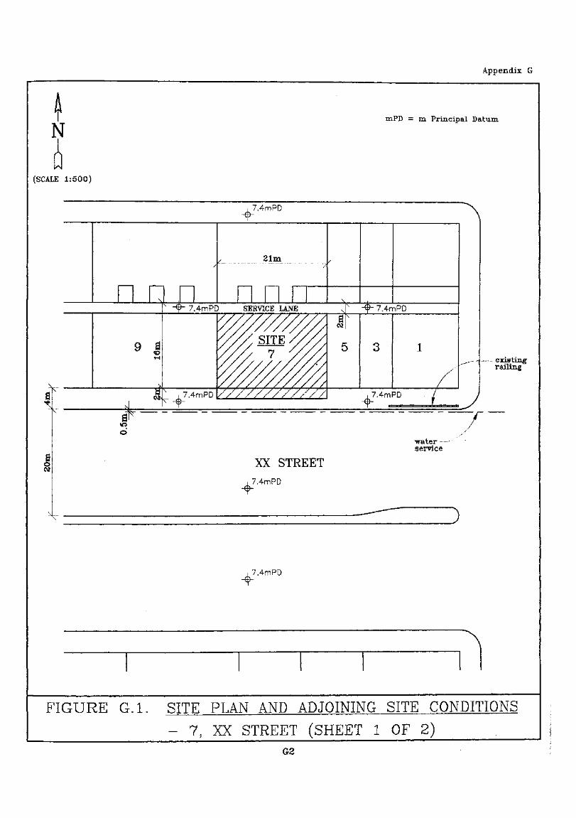
Appendix G
NmPD = m Principal Datum
(SCALE 1:500)
9 I
;7.4mPD
21m
7.4mPD SERVICE LANE
7.4mPD
• 7.4mPD
XX STREET
7.4mPD
7.4mPD
— existingrailing
7"water -—-sei^vice
7.4mPD
FIGURE G.I. SITE PLAN AND ADJOINING SITE CONDITIONS
- 7; XX STREET (SHEET 1 OF 2)G2
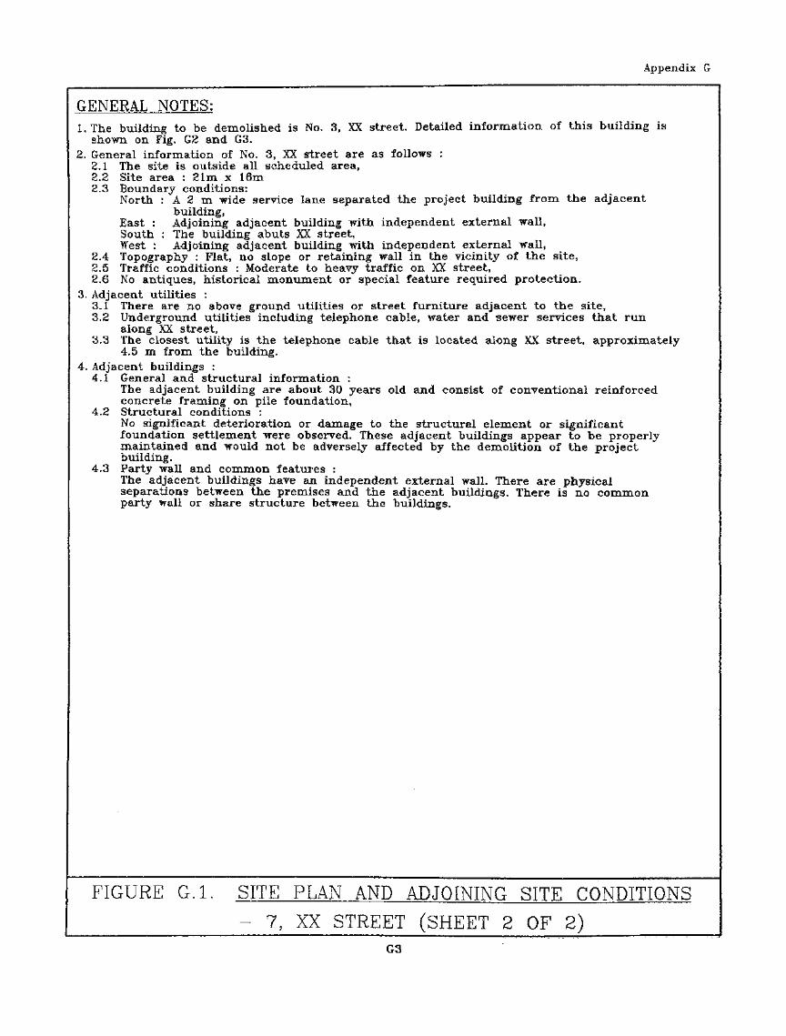
Appendix G
GENERAL NOTES:1. The building to be demolished is No. 3, XX street. Detailed information of this building is
shown on Fig. G2 and G3.2. General information of No. 3, XX street are as follows :
2.1 The site Is outside all scheduled area,2.2 Site area : 21m x 16m2.3 Boundary conditions:
North : A 2 m wide service lane separated the project building from the adjacentbuilding^
East : Adjoining adjacent building with independent external wall,South : The building abuts XX street,West : Adjoining adjacent building with independent external wall,
2.4 Topography : Flat, no slope or retaining wall in the vicinity of the site,2.5 Traffic conditions : Moderate to heavy traffic on XX street,2.6 No antiques, historical monument or special feature required protection.
3. Adjacent utilities :3.1 There are no above ground utilities or street furniture adjacent to the site,3.2 Underground utilities including telephone cable, water and sewer services that run
along XX street,3.3 The closest utility is the telephone cable that is located along XX street, approximately
4.5 m from the building.4. Adjacent buildings :
4.1 General and structural information :The adjacent building are about 30 years old and consist of conventional reinforcedconcrete framing on pile foundation,
4.2 Structural conditions :No significant deterioration or damage to the structural element or significantfoundation settlement were observed. These adjacent buildings appear to be properlymaintained and would not be adversely affected by the demolition of the projectbuilding.
4.3 Party wall and common features :The adjacent buildings have an independent external wall. There are physicalseparations between the premises and the adjacent buildings. There is no commonparty wall or share structure between the buildings.
FIGURE G.I. SITE PLAN AND ADJOINING SITE CONDITIONS
•-. 7, XX STREET (SHEET 2 OF 2)G3
Appendix G
- stairs •• stairs for emergencyaccess use
TJ
C
S-A3
o
S-A4
shaft
3=U
3=u
S-B3
D
O
S-D3 S-E3
S-D4 S-E4
O
shaft
=o
S-F3
S-F4
o
S-H3
S-H4
3* 5m !/ 3*5m \ , 3,5m i / 3*5m > - 3»5m i 3.5m
FIGURE G.2. TYPICAL FLOOR PLAN AND EXISTING BUILDINGINFORMATION - 7, XX STREET (SHEET 1 OF 2)
G4
Appendix G
EXISTING BUILDING:1. General information and dimensions
Age : 30 years (built in 1960's)Use : IndustrialBuilding cover area : 21m x 16mBuilding height : 44m, 11 storeys highFloor height : Ground floor is 5.5 m; 1 st floor and up are 3.5 m,Typical floor plan is shown on the drawing. Elevation of the Building is shown on Fig. G3.
2. Structural conditions2.1 Structure :
The building is reinforcd concrete construction with conventional slab* beam* columnand rigid frame design. It is supported on pile foundation.
2.2 Conditions :The inspection reviewed that the building is well maintained and kept in goodconditions. Other than minor cracks appearing on the finishing, no seriousdeterioration or damage to the structural element was observed.
3. Special structural featuresThe building has cantilever balconies projecting over the existing foot path on XX street,There is no other special structural element in the building.
4. Hazardous materials :4.1 The building may contain asbestos containing materials such as asbestos coated pipes.
An Asbestos Investigation Report (AIR) will be conducted by a registered asbestosconsultant. If asbestos containing materials are found to be inside the building, anAsbestos Abatement Plan (AAP) will be submitted to the Emvironmental ProtectionDepartment 28 days before the asbestos abatement work commences. The asbestosabatement work shall be conducted in accordance with the Air Pollution. ControlOrdinance and the Factories and Industrial Undertakings (Asbestos) Regulation. TheAIR and AAP will be submitted separately to EPD.
4.2 Handling of hazardous materialsIf asbestos containing materials and/or chemicals are present on the premises, allasbestos containing materials and/or chemicals shall be removed by registeredasbestos contractor in accordance with Environmental Protection Department andLabour Department regulations prior to the commencement of the demolition work.
FIGURE G.2. TYPICAL FLOOR PLAN AND EXISTING BUILDINGINFORMATION - 7, XX STREET (SHEET 2 OF 2)
G5
Appendix G
mPD = m Principal Datum
,2m,,3.5m ,,-3.5m K3.5m .,3.5m'
, ..--water tank/ .,- steel/ f sheds /
• stairhood
7.4mPD XX STREET 7.4m\y —
PD
"T™ /
1
/i a
«
j<
5
<
1
t
.. j
i
j,- 4m K-/f ~" " A
R/F
10/F
9/F
8/F
7/F
6/F
5/F
4/F
3/F
2/F
1/F
G/F 7.4mPD
^Building behindservice. lane
FIGURE G.3. ELEVATION A - 7, XX STREETG6
Appendix G
, , , 3 . 5 m7T " 7T "'""
double rowscaffolding
tarpaulin& net
catehfan
catcliplatform
-truck eraB.e130 ton
coveredwalkway
3.5m ,,,
...water tank^ steel stairhood
( sheds /
ff'l' • - /
(JN\
N ^\ f
xj(
)(
l]
b*s -
3^ ^
— . .
mum i
X '
_,
_. -j
V
i
-
X/ /
f ,
r
**
<\
^
x
/_
. ....
'f
~
• •"••^ KmH
. »•>—
^
n F«»
nan
scaffolding
)p j- o
S\ , St€
»l an
foi/ thiv at
I no15
yf) f \ at i\ no i1 thai
I/
}\ ta
') / &
*i j>I/
)} ,w-
**"'
pping
el brackeld anchors* snpportiie scaffoldiintervalsmore tha
m
Manntervalsnorei 10m
rpauliiinet
atchjlatform-VA
covered/ walkway
CO
O
R/F
10/F
9/F
8/F
7/F
6/F
5/F
4/F
3/F
2/F
1/F
G/F
FIGURE G.4. DEMOLITION PROCEDURE AND SEQUENCE
____________ (SHEET 1 OF 5)G7
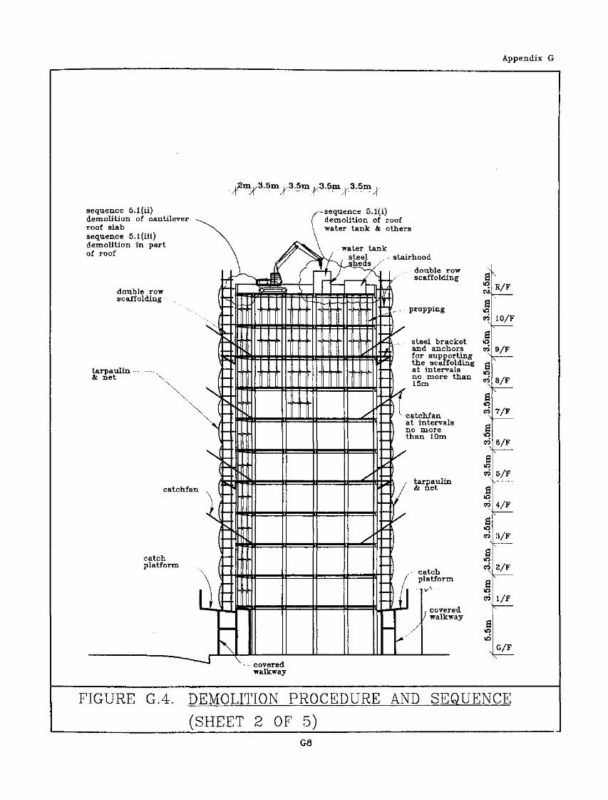
Appendix G
sequence 5.1(ii)demolition of cantilever -~.roof slab ^^Vsequence 5.1 (in)demolition in partof roof
double row 'scaffolding .. ! •
'""""" •-••X i
xss(£ net '\ /
\ (V
\
\i(catchfan N I
il(
catch /platform /
\ I
Ll
\L ,X
«s
X
X4
_»_ tit
X
::
rf*vnf
\
2m. 1/3. 5m i/3.5m/["" A " ' 7
(
. /(
_ ^ *•
1II
I
JUL
.UL
JJB
11§I
^^L^N _
/3.5m 1/3* 5m ,/- "/r - /!
/—sequence 5.1(demolition ofwater tank ^c
\\ ..-.water tan^y steel
> /
"s^--
/ \•j)
^^_^^
TK
;
/''•
^
s
i)roofothers
k. • - stairhood
,. double row ^/-1'' scaffolding 3
/ \ Csi,£..u . a^ L- -- propping o*"\ °°x
X* e-f ct-. \ , - • St€-^1 al1
^/ th-4 at
! n o15
"" / ^-catc311 at i
no ithai
~-Vt)
_J/
— ii:) ,=) / 1— /
^^^-J v coveredwalkway
FIGURE G.4. DEMOLITION PROCEDURE AND
3sel bracket &od anchors co• supporting ^e scaffolding gintervals jgmore than •
m \
hfanntervals dmore Ni 10m ^
oo\^
rpaulinnet d
»D
1
atchlatform -
covered/ walkway a
R/F
10/F
9/F
8/F
7/F
6/F
5/F
4/F
3/F
2/F
1/F
G/F
SEQUENCE :
(SHEET 2 OF 5)GB
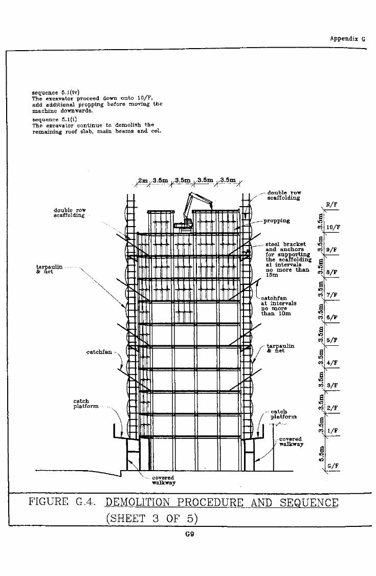
Appendix G
sequence 5.1(iv)The excavator proceed down onto 10/F,add additional propping before moving themachine downwards.sequence 5.l(i)The excavator continue to demolish theremaining roof slab, main beams and col.
.^m^d.Sm ,/3.5m ^3*5m v3*5n7r~ A "~ ' A " "/i " ST
double rowscaffolding
tarpaulin •.,& net \
double rowscaffolding
propping
steel bracketand anchorsfor supportingthe scaffoldingat intervalsno more than15m
catchfanat intervalsno morethan 10m
catchplatform
catchfantarpaulin
net
catch,platform
covered/ walkway
\,coveredwalkway
00
10/F
9/F
8/F
6/F
5/F
4/F
3/F
1/F
G/F
FIGURE G.4. DEMOLITION PROCEDURE AND SEQUENCE
(SHEET 3 OF 5)G9

Appendix G
sequence 5.2(ii)Remove all beams, col., wall andother structures on 10/F,
sequence 5.1(il)Remove cantilever structure betweengrid 5 & 6 on 9/F, .
sequence 5.1(iii)Demolition of remaining 9/F,
The procedure/sequence repeats as itreaches the ground level, and proppingto be installed accordingly.
j2m.y3.Qm -,3.5m ,/3.5m .,3.5m v-7T " /T 7T" ~/r — — 7f • A
double row /scaffolding 1 ^r^
""--, | ^
1-tarpaulin — - -. / "*" '& net \ A — .
\ (ElV_
/y
catchfan , ( *
Hcatch / —platform /
LJjEi
\
\
,
1ftI
"ifl«. «UJ
> k «f
SX
^
' 1y
/'
^
. d o u b l e row_?/
x' scaffolding
Q i1-^ 1 jS^ afc-L__ steel bracket »q*\ and anchors oi
1 the scaffolding g— i at intervals ^§~~\ no more than •
15m ^
-Irf a""/ ^catchfan ^— Xat intervals d-* 1C no more P_ / than 10m ^
— ls*^ d
2 1
::1 riI catch \
"~"\ / S- / I f r fjf J f i
/ walkway_ / . S
\
10/F
9/F
8/F
7/F
6/F
5/F
4/F
3/F
2/F
l/F
G/F
•* coveredwalkway
FIGURE G.4. DEMOLITION PROCEDURE AND SEQUENCE
(SHEET 4 OF 5)G10
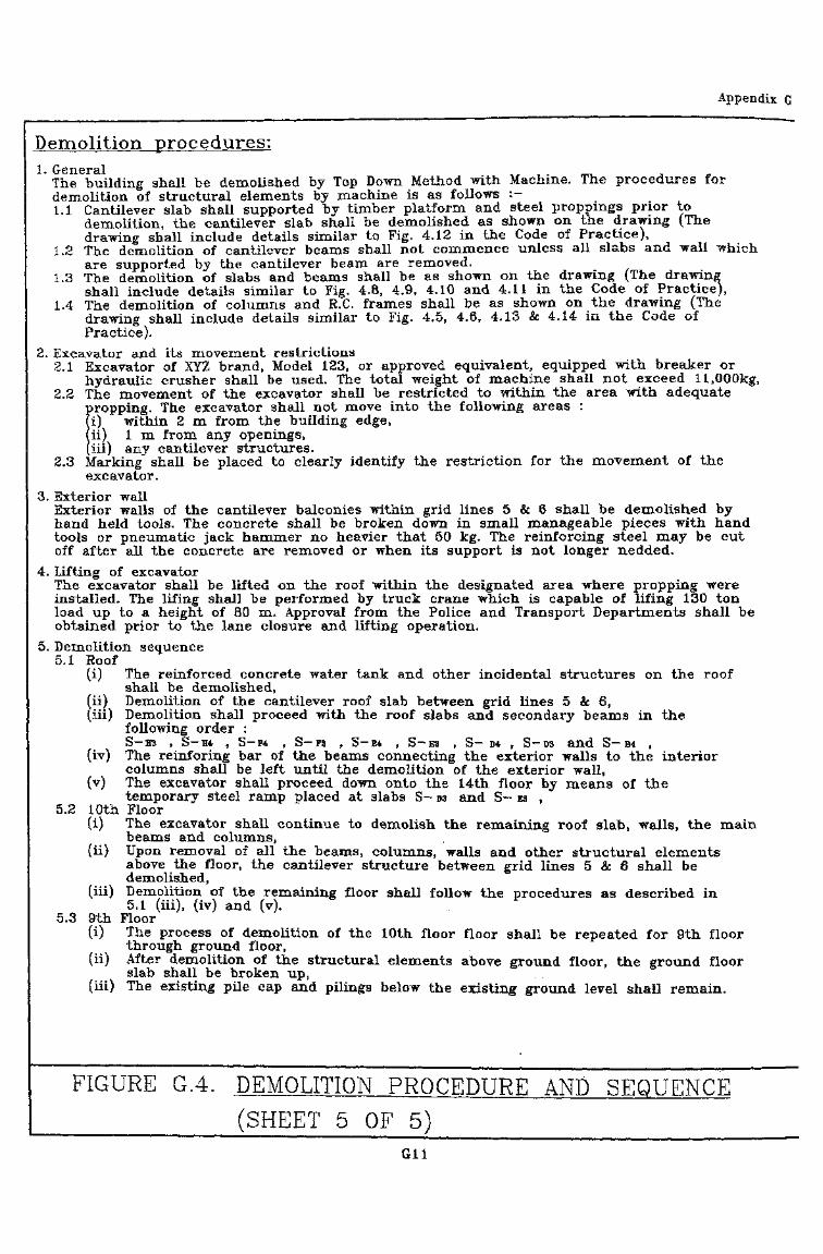
Appendix G
Demolition procedures:1. General _, _
The building shall be demolished by Top Down Method with Machine. The procedures fordemolition of structural elements by machine is as follows :-1.1 Cantilever slab shall supported by timber platform and steel proppings prior to
demolition, the cantilever slab shall be demolished as shown on the drawing (Thedrawing shall include details similar to Fig. 4.12 in the Code of Practice),
1.2 The demolition of cantilever beams shall not commence unless all slabs and wall whichare supported by the cantilever beam are removed.
1.3 The demolition of slabs and beams shall be as shown on the drawing {The drawingshall include details similar to Fig. 4.8, 4.9, 4.10 and 4.11 in the Code of Practice),
1.4 The demolition of columns and R.C. frames shall be as shown on the drawing (Thedrawing shall include details similar to Fig. 4.5S 4.6S 4.13 & 4.14 in the Code ofPractice).
2. Excavator and its movement restrictions2.1 Excavator of XYZ brand, Model 123, or approved equivalent, equipped with breaker or
hydraulic crusher shall be used. The total weight of machine shall not exceed 11,000kg,2.2 The movement of the excavator shall be restricted to within the area with adequate
propping. The excavator shall not move into the following areas :m within 2 m from the building edge,hi) 1 m from any openings,(iii) any cantilever structures,
2.3 Marking shall be placed to clearly identify the restriction for the movement of theexcavator.
3. Exterior wallExterior walls of the cantilever balconies within grid lines 5 & 6 shall be demolished byhand held tools. The concrete shall be broken down in small manageable pieces with handtools or pneumatic jack hammer no heavier that 50 kg. The reinforcing steel may be cutoff after all the concrete are removed or when its support is not longer nedded.
4. Lifting of excavatorThe excavator shall be lifted on the roof within the designated area where propping wereinstalled. The lifing shall be performed by truck crane which is capable of lifing 130 tonload up to a height of 80 m. Approval from the Police and Transport Departments shall beobtained prior to" the lane closure and lifting operation.
5. Demolition sequence5.1 Roof
(i) The reinforced concrete water tank and other incidental structures on the roofshall be demolished,
(ii) Demolition of the cantilever roof slab between grid lines 5 & 6,(iii) Demolition shall proceed with the roof slabs and secondary beams in the
following order :. S-H3 t S-H4 , S-F4 , S-F3 , S~E4 , S~E3 , S- D4 , S-D3 and S— B4 ,
(iv) The reinforing bar of the beams connecting the exterior walls to the interiorcolumns shall be left until the demolition of the exterior wall,
(v) The excavator shall proceed down onto the 14th floor by means of thetemporary steel ramp placed at. slabs .S-D3 and S-ES ,
5.2 10th Floor(i) The excavator shall continue to demolish the remaining roof slab, walls, the main
beams and columns,(ii) Upon removal of all the beams, columns, walls and other structural elements
above the floor, the cantilever structure between grid lines 5 & 6 shall bedemolished,
(iii) Demolition of the remaining floor shall follow the procedures as described in5.1 (iii), (iv) and (v).
5.3 9th Floor(i) The process of demolition of the 10th floor floor shall be repeated for 9th floor
through -ground floor, . -: 'V : • \ , . ' . ' . : ' • • • ' ' • " '(ii) After demolition of the structural elements above ground floor, the ground floor
slab shall be broken up,(iii) The existing pile cap and pilings • below the existing ground level shall remain.
FIGURE G.4. DEMOLITION PROCEDURE AND SEQUENCE(SHEET 5 OF 5)
Gil :
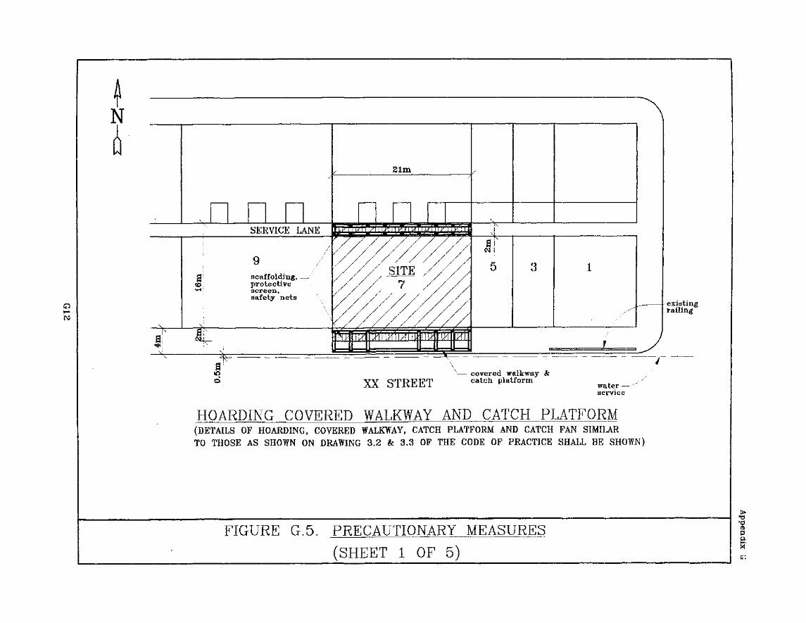
N
ro
scaffolding,protectivescreen,safety nets
XX STREETcovered walkwaycatch platform
water —service
HOARDING COVERED WALKWAY AND CATCH PLATFORM(DETAILS OF HOARDING, COVERED WALKWAY, CATCH PLATFORM AND CATCH FAN SIMILARTO THOSE AS SHOWN ON DRAWING 3.2 & 3.3 OF THE CODE OF PRACTICE SHALL BE SHOWN)
FIGURE G.5. PRECAUTIONARY MEASURES
(SHEET 1 OF 5)
fbPp.

Appendix G
5"N. ^
/ -~-,
6
- stairs
1 p
S-A3
S-A4
shaft
ZFO
S-B3
S-B4 S-D4 S-E4
stairs for emergencyaccess use
liftshaft
S~F3
S~F4
=n
S-H3
S-H4
3,5m 3,5m 3.5m 3.5m 3,5m
PROPPING SCHEDULEPROPPING No. OF FLOORS BELOW
j I1 _ 1
AREAcantileverbalconies
generalfloor
rarrm
BEARING CAPACITY
25kN
25kN
45kN
SPACING
1.2m
1.2m
1.2m
REQURE PROPPING
all floors
3
4
FIGURE G.5. PRECAUTIONARY MEASURES
________ (SHEET 2 OF 5)
Appendix G
- -ft- - --^j^-—— _^- -^ -^
water tank/ x- steel/ f sheds /
•
double row /scaffolding----.....
>J
(& net \ /•
\ "4\ (xi<
catchfan x I
(catch /platform /
MXX STREET
k_ .
«
_
X,-^v_ .
~" •
M^
^s;
-'
HBHB
\
-
r
' . /
JJJb
/Tl
..
*
1 1 1
.'
'
^
I~
•f
sj — <
1 EM
Z
~•Ml
stairhoodi
- - double row ^// scaffolding q
\1 , ." propping ^\ 00
u) ^r a\ - steel bracket »Oj and anchors co
for supporting ">-/ the scaffolding gi at intervals ^,\ no more than *J 15m °?U a1
U «./ - catchfan \\ at intervals ^} no more S/ than 10m ** 00
Y s) %J / & net g
)/ a
! 5\ SJ catch' / platform ^
)l A M
Jj s/ walkway
1> '"""" . »O
\
K/P
10/F
9/F
8/F
7/F
6/F
5/F
4/F
3/F
S/F
1/F
G/F
v coveredwalkway
FIGURE G.5. ELEVATION
(SHEET 3
A
OF
- PRECAUTIONARY MEASURES
.5 )G14
Appendix G
rRECALTIQNARY MEASURES:Prior to tht* demolition of the main building ^truolur*.!, the following prcra i i t ionarv ni^ibhali he carried out, :
L I ' t iht ies disconnectionMl utilities? and. services to the building shall be terminated.. The srwcr and drainageconnections shall be plugged at the terminal manhole,
I .?. Covered walkway and catch platformv« Co\ered walkway and catch platform shall be erected according to t h r approved p lan
by Building Authority along the entire length, of the property boundaries on XX St r roLarid the service lane* The "covered walkway and catch'platform foundation instal lat ionshall also comply with the conditions of the Excavation Permit by the HighwaysBe par tin en I If necessary,
(B) The carriageway shall be located, on. XX Street between grid, lines E & H,(Cl The catch platform along XX street shall be extended underneath the entire area of
the 1 st floor cantilever balconies.
3 Scaffolds5 screen and catchfan(A) Double row scaffold with, net and tarpaulin shall be erected to cover the entire building,(B) The installation of the scaffold, net, tarpaulin and catchfan shall be in accordance with
the Code of Practice for Scaffolding Safety and the Code of Practice for Demolition ofBuildings,
(C) Bamboo catchfan shall be installed around the building at vertical internals of no morethat 10m.
4. Temporary support(A) Propping shall be installed to support the operation of the mechanical plant and the
demolition activities. The propping requirements for different floor areas were selectedbased on the recommendation of the Code of Practice for Demolition of Buildings. Thepropping Schedule is summarised in Figure G2,
(B) The top and bottom supports of the. props shall be adequately secured. Bracing and/orlateral restraints in at least two directions shall be installed to prevent lateralmovement of the props. Propping shall not be removed unless the support for themechanical. plant, debris or other loading conditions for the demolition process is nolonger required,
(C) A structural steel access ramp shall be provided fuik the excavator to manoeuvre downthe floor. The grade of the temporary ramp shall not be steeper than 30* or asrecommended by the manufacturer.
(I)) Timber platform with steel props shall be installed underneath cantilever beams and,slabs.
5. Debris handling5.1 The steel sheds shall be dismantled. All trash, furniture, timber, door framed, windows
shall be removed from, the building. Any salvageable items shall be sorted and removed,separately,
5.2 Debris shall be conveyed to the ground floor through the. lift shafts between grid linesG & H. The areas near the lift entrance shall be barricaded. Approximately 175 cu. mof building debris would, be generated from the demolition of each floor. Clearing andtransportation of debris shall be arranged to ensure the following conditions are'maintained at all time :A) Accumulation of debris in the lift shafts shall not exceed I m high.
Temporary storage on-the floors shall not exceed 100 mm above the floors,C) Debris accumulation on the ground floor shall, not exceed 1 in above the ground
floor slab,(D) No debris shall be accumulated on the cantilever structures.
6. Special site safety8.1 ' Emergency ' exit
The staircase between grid, lines B and C. shall tse used as emergency exit route. Theroute shall be cleared of debris at all time. Identification signs and/or marks shallused ' to clearly indicate the route,
6.2 Fire prevention . ' . . ' . ' . "Fire extinguishers shall be placed at a convenient-location on each floor. Ail gasoline,flammable materials, oxygen and acetylene bottles shall be stored in a protected areain accordance -with, the Factories and • Industrial Undertakings Regulations,
FIGURE G.5. PRECAUTIONARY MEASURES
__ (SHEET 4 OP 5)G15
A p p e n d i x
F>_MCAUTIQNARY_MEASURES:6.3 Training
A competent trainer shall train ail on site personnel. The training programme shallinclude the following :(A) An induction course at the beginning of the project to provide the opportunity
for on site personnel to 'understand the demolition procedures, sire safety rulesand critical safety concerns of the project,
(B) Daily safety meetings to reinforce the safety concept,6.4 Dust and noise
(A) Dust generated during the demolition shall be suppressed "by spraying watercontinuously during the breaking operation, ' "
(B) All jack hammers and excavator mounted breakers shall be equipped with silencerattachments. The air compressor shall be super silence type. Demolition work shallbe performed within the restricted hours from 1900 hrs. "to 0700 hrs. all day andfrom 0700 hrs. to 1900 hrs. on general holidays including SUNDAY. Mobile aircompressor shall be placed on ground floor,
7. Maintenance & inspection7.1 Inspection shall be performed by A.P and KSE on a weekly basis and contractor on a
daily basis to ensure that all the temporary structures, catchfans and catch platformsare in good conditions. Any accumulation of debris shall be removed. Any movement,damage or distortion to temporary structures shall be identified and repaired., ifnecessary. The inspection and repair activities shall be recorded and copied to the AP.
7.2 Contractor shall also inspect the site, daily, to identify any unsafe condition, such asdamage to the temporary supports or unstables and/or partially demolished structuralelements. Any unsafe conditions shall be rectified before leaving the job site.
7.3 Inspection and maintenance .of scaffold shall be performed, in accordance with the Codeof Practice for Scaffolding Safety and the Construction Site (Safety) Regulations by thecontractor.
8. Emergency plan8.1 Emergency telephone numbers shall be post in conspicuous locations. In case of
accident or emergency, the contractor shall report to the Police and Fire ServiceDepartments for immediate assistance. The contractor shall also contact the AP andRSE immediately about the incident.
8.2 Prior to a typhoon warning the following items shall be performed :8.2.1 All the temporary supports, scaffold, screens arid any loosd materials shall be
secured. The scaffold shall be taken down to the prevailing top level of thebuilding,
8.2.2 Flammable materials shall be removed or stored in 'a protected areas,8.2.3 The excavator should be moved to a location with proper support, preferably
•close to the centre of the building,8.2.4 Any unstable and/or partially demolished structure shall be completed. If it is
not practical to complete the demolition timely the unstable structural elementshall be braced and supported.
9. Post demolition9.1 The site shall be levelled and clear of debris,9.2 If the new development is not immediate, the property boundaries shall, be properly
enclosed to prevent public entrance, • • • • . , •••9.3 Any damage to pavement, footpath and elements within the right of way shall be
repaired, to its original, conditions prior to the completion of the -'demolition- project.
FIGURE: G.S. PRECAUTIONARY MEASURES(SHEET 5 OF 5)
G16
APPENDIX HAppendix HFlow Chart forCurrent Demolition Procedure
I Organise testingand checkingof hazardous
I material
Developer initiatesdemolition work andappointment of AP/RSE
AP & RSE to1. Review record plans,2. Inspect the site and
PermitRejected
Building to bedemolished
Apply forHoardingPermit
Submit1. Demolition Plans and j2. Stability report
omment Disagreeby N ^
EPD
Agree
approved
| Apply toJ Highways DeptJ
I for ExcavationI Permit
Yes
PermitIssued
ExcavationPermit \
|v
Submit I1. Site Safety Supervision
Plan and notificationof TCP
2. Personal particularsof operatives ofPowered Mechanical jPlants or Equipments I
PermitIssued
Note:
1, This flow chart applies to common*methods of demolition, excludingspecial methods such as wreckingball and implosion.
2, The Building Department will be thecoordinating department for centralprocessing of Hoarding Permit andDemolition Work, except forExcavation Permit, Hazardous MaterialRemoval and Soil contaminations,
3, Submission of specified forms areexcluded in this flowchart.
4, Legends:AP = Authorised PersonRSE = Registered Structural EngineerRSDC= Registered Specialist Demolition
Contractor
BD = Building DepartmentEPD = Environmental Protection
Department
TCP = Technically competent person
Demolition workon site
AP/RSE/RSDC inform BDupon completionAP/RSE certify structuralsafety of remainingworks on site
FurtherYea maintenance
ot Jtemporaryworks
Contamination
discovered
txecking: Rejectedby > >
FIGURE HI FLOWCHART FOR CURRENT DEMOLITIONPROCEDURE IN HONG KONG
HI

^ft « antr
«lf^ ' ' J^
I • Sitt'
®^ffifi90% ' '• it I'J^m^J^ -fi»p tS '
« '> &m
' • I lBt
0fWHtBa^m^^^ iiJ^^«^^{imiffl'
1.1
1.2
2.1
2.2
2.3
4.1
4.2
4.3
4.4
mm
3.1
3.2
3.3
3.4
3.5
3.6
3.8
3.9
3.10
3-12
ii
i
4
4
9
11
12
12
12
20
23
26
32
34
34
37
38
41
42
43
43
43
75
77
6.
4.5
4.6
6.1
A
B
C
D
E
F
G
H
PI to
m
5.1
5.2
5.3
5.4
5.5
5.6
5.7
5.9
5.10
80
83
91
91
93
100
102
103
103
104
105
107
108
110
110
112
116
120
123
126
'•gvm 129
146
162
3.1 WMrAMHi
:3.2
:3.3
:3.4
:4.1
'C-l
14
14
22
31
44
122
m
AT
96
Z6
£8
58
8Z,
9L
VL-ZL
\L
89-A9
Z9
09
8S
LS
rs
zt>!
I t> !
01 > I
6>
zs
6T-SI
£1 re :
ffi 9 O O O 71 71 hrtto
nnns
hffim
i&
si ^
$^ ^^ «lIt giw 3ni"40 ^
It*
man)EE
Osto
4^ U> U) U)O ON L* u>
1. ffi&1.1
1.1.1
(A)
(C)
•
. 1.2 ^
^t - XfK >is -
1.1.3
9 {H^f^^/^M^lH^OI i LyTb^/jyT: p3 /|\DC''5i?v^ W -J H*lj.» -,
(«S)
1.2
W '
r m «r A± jo>)(c)
47
• '^tfT^ »^fi§ «B IS ) ' MM
> -
' -9 mmv
rW^frASStj
'tl
*
2.
2.1
> M' %
-
2.1.1
(A)
(B)
Afrit *
(2) ; n
(3)
;
(4)
(5) ffl>

fe)
mmmm (i)
(0)
• ffidltf (OT)
(6)
' (8)
a)
(9)
2.1.2
(A)
it • mm
(B)
(1)
(2)
(3)
(4)
(5)
(6)
(7)
(8)
(9)
(ii) mimmmwtwffim >
(«)
(z)
ffi (p)
: 00
' filffllli- (T)
fiiffild^M (v)
t'l'Z
'
'
(a)
«
(e)
(z)(i)
& O)
(c)
(d) '(e)
*1 t/fe*L^^C -JIJ&W7
(3) H6HHI ' J
* * g&*« * *
(4) -ISffllff '
(5)
(6) ' J
(7)
(8) -I
(9) —f
•fe
(a)
(b)(c)
(B)
m•S^tEf^lS^OTmfr:
!tJ *
(1)(2)
(3)
(4) n
(5) $nJWg«<»^!^tJ*fP^W}l§'mfe
2.2
(6)'
^ ^ i ^. -
B
2.2.1
' E Rl Ail
(A)
(B)
2.2.2

2.2.3
(A)
(B)
(E)
(F)
(G)
(H) ?57j«
'
>
2.2.4
(A)
(1) $;
(3)
'
10

(B) -mm> '
2.3
'
2.3.1
2.3.2
11
3.
3.1
t:>C;±i^
3 "%.2
3.2.1
ff
(A)
(B)
(Q -^ '4
CD)
12
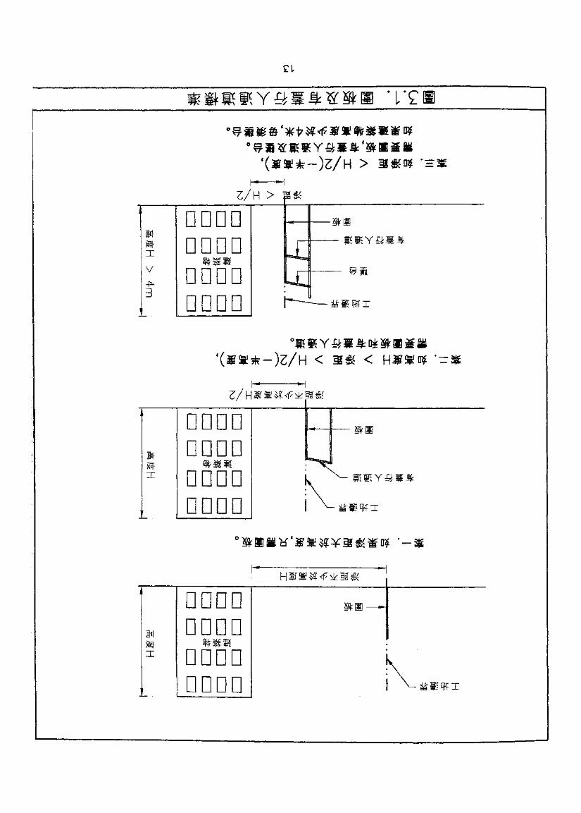
Z/H > j
W}
V
3
DDDOD D D DD DO* DDDDD i
s*
iu.h—— **WI
,
1*jT
DDDDDDDDDDDDDDDD
saaa*feaH
....„ vri. rapi^ft S)
K «*!Y«**vtftsffl
DDDDD D gQD D !fDDDDD
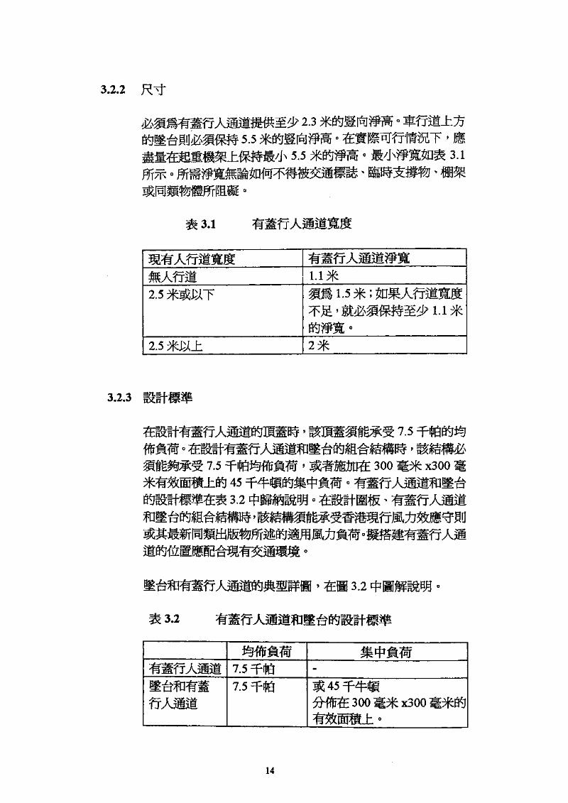
3.2.2
2.35.5 jg[p]}» ° o
5.5 #$flW • ft/J
*
3.1
3.1
2.5 1.5 ;
2.5 »
' 7.5
• '7.5 Ttt*%ffij JIW ' ^»D« 300 m^ x300 %±^ 45 4 1141 n^f
3.2 ^^I^HJ '
3.2
7.57.5
14
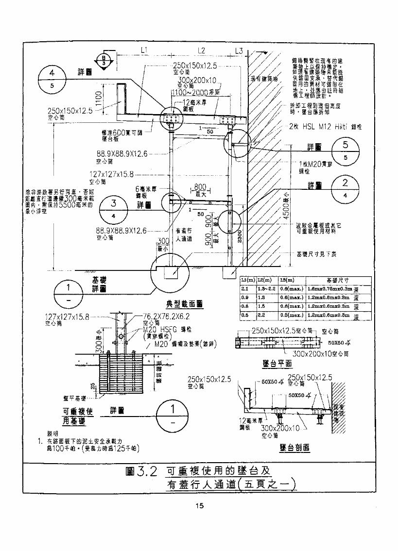
-H- -•-250x150x12.5
00x200x10
250x150x12.5 -
2ft HSL M12 Hiltif 1600* W ISIS*
88.9X88.9X12.6
127x127x15.8- -—4
.9X88.9X12.6-
6.2X76.2X6.2S'UlM20 HSFGi n/-M20
127x127x15.8 •
—r-250x150x12.54'
300x200x1 OS'{
250x150x12.5
300x200x10-
3.2^d ITJ A -V
Xl
15
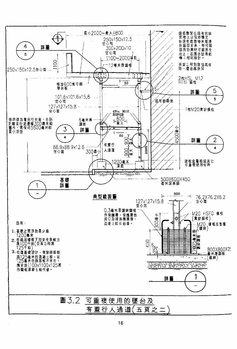
*480Q250x150x12.5
300x200x10
J
250x150x12.55'D
S 16001^1
101.6x101.6x15,8 -£'i>io
127x127x15.8
88.9x88.9x12.6
500X600X450
76.2X76.2X6.2127x127x15.8
00x1100x1251
1.6

600
-KD&OoO
oooC\j
cxi
63.
r!. i
ii__;— i
-iJ
— -
iff
,.
fc
-
1 52X1 52X1 5. 8 ,/ \ 6 001 °1 1
1
53.5X7.9
— —4j
ii
r—-
{',
1 '
D
_„_
432x102x65,54
....
1;JJ
L-
./*'"'
j —f—iiif~
""dp
/
—
—
152X152X15.8- — -
a
_ . .>-
~i
\^x
^ _ .
N\\
- 4
— i
ii ^Li
|
- A^ ^YA"^ RY7 Q
01
oo •j
250x1 25x'
127x127x15.8S^M--
152x152x15.8£'&a-'
3.9x88.9x12.6
63.5X63.5X7.9" ' -
27x1 27x1 5. 8 S*
50x504.
. 432x102x65.54
TTTTrU
L2400!1 JJ400(**X.
•FT "
0
152X152X15.8
2400(1^)127x127X15.8
r—1000H
~ \- H
• 1000H
All
LJ432x102x65.54^*
4~~ i xi3£i X
-fr A m
17
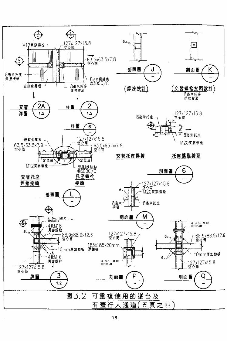
127x127x15.8~
-53.5x63.5x7.8
BMMilp©300C/C
fg&Rif)
127x127x15
127x127x15.8-^-r 63.5x63.5x7.963.5x63.5x7.9 -,
@300C/C4127x127x15.8
M 201 S* t
127x_127x15.8
185x185x20mm.
88.9x88.9x12.6*-A- j. ,J ^ ;|\
.\X i~~: i
x--10mmfio»*
127x127x15.8127x127x15.8
88.9x88.9x12.6
3.2
18

21*1152x152x15.84.
lOmmliQSf-
,•—152x152x15.8^*1r-4No. M16
HSFGB
-270x170x201*1
4No. M16-HSFGB
±±}a"\X, V -rs- I
~ 88.9x88.9x12.6
10mml
8.9x88.9x12.61,j>Sj L
V6l5x63.5x7.8\
4t HSL M12-
mm
iff/jtfti
152x152x15.64-
2.
3.
4.
5.
6.
7.
8.
f/fftt°
Bfrf '
11*1*4604
fa)
-(b)
152x152x15.8BBS
ti
3.2
19

3.2.4
3.2.5
'
- mm. -r—1_ rajcft.-y-r Jr
££sF^*
3.2.6
50JlS 35
18 S^ 201: > 600 *
3.3
3.3.1
20
(A)
(B)
(C)
>
,
i^vjiE 1 J i
milii 4
15 # ' 15
If )
^-'
U -
^ISi 2
21

3.3.2
(A)
^fj-a-s> -TV ESI /-4-*7^aEilrroi
(C)
Ity1^ 300 ^
(1)
^?
3.3
3.3
1620
130
(D)
22
3.4
BS 586? B
(2)
(3)
3.4.1 *g;£
101.5
20 SM 45
3.4.2
±-
3.3
(A)
(SEft) ± •
1-3
23
n
T-
(a)
e
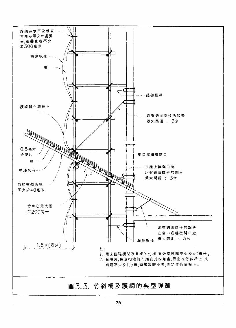
3.3.
25
3.4.3
• £nn;£
>
»'
3.5
3.5.1 fl
(A)
(i)nllCT .
(2)
(3)
ffi^fwaw^^a^ 0 $pwei :
26
(B) 1
^ • »•
'
(Q
(D)
•> * ^ fflfc - gfct±% • -
'
iimmi •
27

(3)
(a)
• m%-wmm
(D)
•
«o
* •* *
(V)
(a)

JWfr
3.5.3
(A)
(1)
(2) i
(3)
^ 1.5
•£fp
1X1
• 1-25
(B)
'
(l)3.4 {«^ •
(2)
29

(3)»
(C)
(2) ' 11
(3) &
3.5.4
(4) iK^«aiE«fiW
3.5.5
ffti
3.4
30
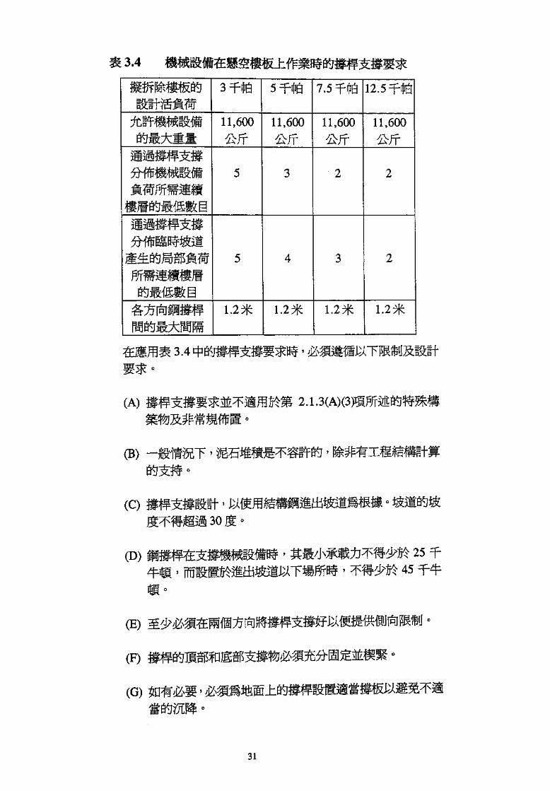
3.4
7.5 12.
11,600 11,600 11,600
Alt11,600
mm
1. 1.27ft 1.27ft 1.27ft
3.4
(A)
(B) -j
(C)
(D)
'
2545
(F)
(G)
31
3.5.6
(A)-
• '
(B)
(C)
•
• • M
3.6
3.6.1
•
3.6.2
-
(A)
32

(1)
(a)
(b)
-m
(2) H
(3) ^frfr
(B)
10
10 ^ > 7JCM: 3 : 6.0
T-
± '
3.6.3
33
rre
'
L'£
«
'
'
(A) i
(B) ^Wl
(C)
(D)
(G) &?$ffl33
(H)
3.8.2
3.8.3
-
35
3.8.4'
»P°P ' -
fa '
'
3.8.5
(B)
(Q
(D)
(E)
3.8.6
3.8.7
' £H 3.8.6
?BS T K:& Tiip 'f&'fTOiiii r H^y^-J-^/PIX/X—L-*^TC/jni £3 I^S/ll/X.^B^^TCj>v H- I
(G)
•
i$I6Wl»J
:
i.2. *
3.
4.
1
• SS«§ffib 15 *
3.9
3.9.1-
3.9.2
*
fr .-
37
3.9.3 7JC
m * m&^mm7^mmmmm^mw
3.9.4
' •S ' ( ) (
3.10
3.10.1
cIf T
38
(A)
(B)
iffWP^v
(C)
' m-'
WJ>ffi6*'m
+£
(D)
7ft x900
^I >•
• £!£if
3.10.2
39
Ofr
9'OT'€
g^TfSWfOTfi (a)
'
j •
s.ii #titjfti&i
• -
>
' fnB»!W6«filt} '
m
R*ft£ ' «lRl^±RlS^'If« ' ]
^EJt|n
(Q
41

(i)
(ii)' &£
(iii)
3.12
(A) w^-mn
(C)
3.11•
CD) s Mi//]urai °
(i)
(2)
42

•
•
mm (v)
<• •
• ®•
fflSfel
g 8 i
iI H••i _ i
N^^
Y-1S
£**
fcHS
o o O O o oO o oO o o O o oO o o O
O o o o o oO o o o o o o
s«P:OB:
-K:
-E
s
m •K
OS •it
o F$
m
O
00 <1 ^ -Jo <-ft o o
giiU 5111jtitti j5ff
)m
o o
at
n
at
si
o
©
3
lilt
;>-
1
o
o o© ©
•.m
m&m
o
o
o
o
o
o
o
o
o
o
o bf
^Kg
H
WHS
m
o o o
©
fta*
;S
(B)
(i)
(2) '
(3)
(4) iK
(a) mm
gfc
(5)
(6)(7) $
(C) m --n
,__• >___&/*46
'
5.3
> 4.2.
"5 -C3.5
(2)
(3)
WrlOTtSSliia' ^Iits ° B 4.2 l
(5) n
(D)
(1)
'AW • 4.6.3
(a)
(b)4.2.1(0X2)
4.2. l(D)(3)fn 4.2.
•
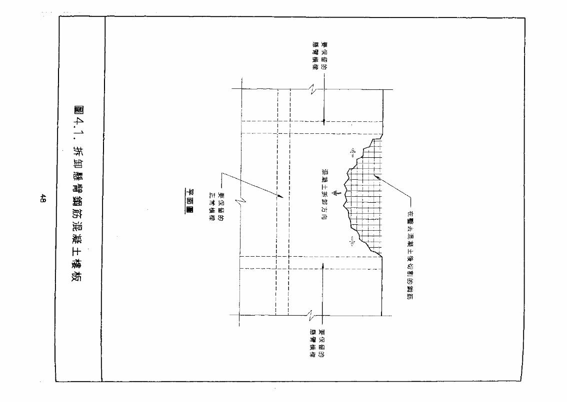
jtoL"
00
hh
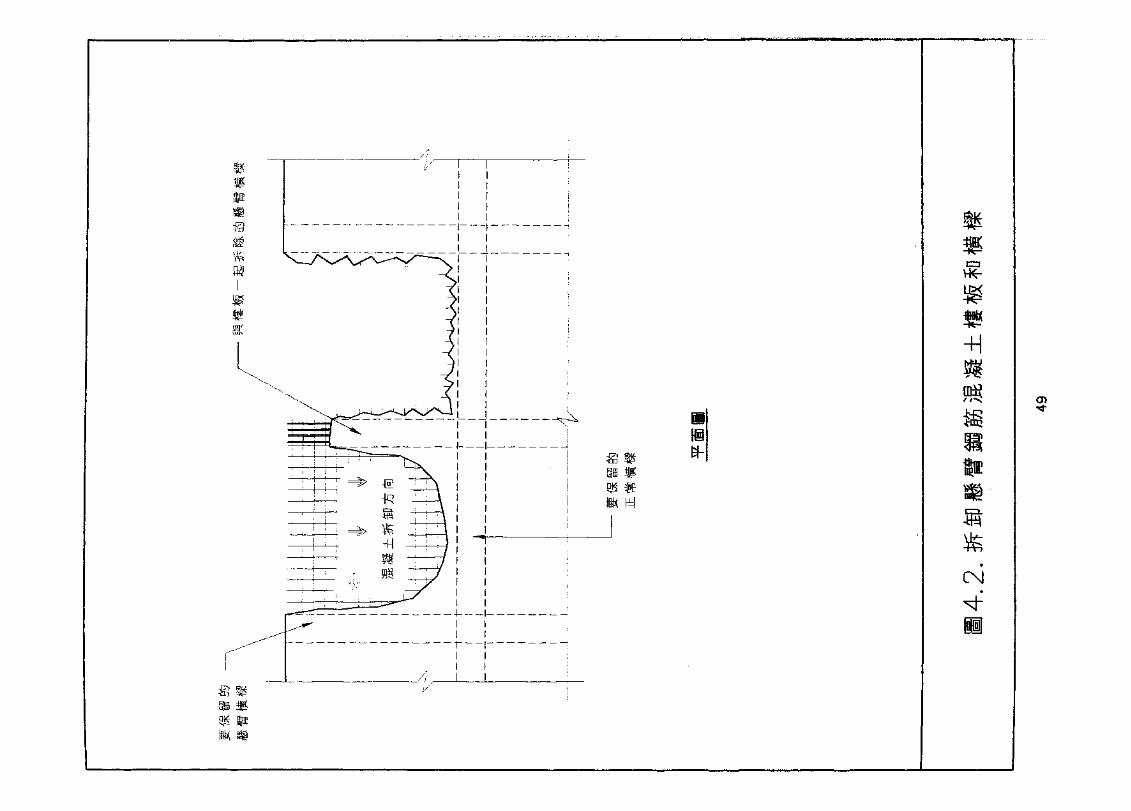

(2)(a)
4.3 1
(i)
±
(iv)
(3)
(a) > 4.5
(0
± - i l
(iii)
50
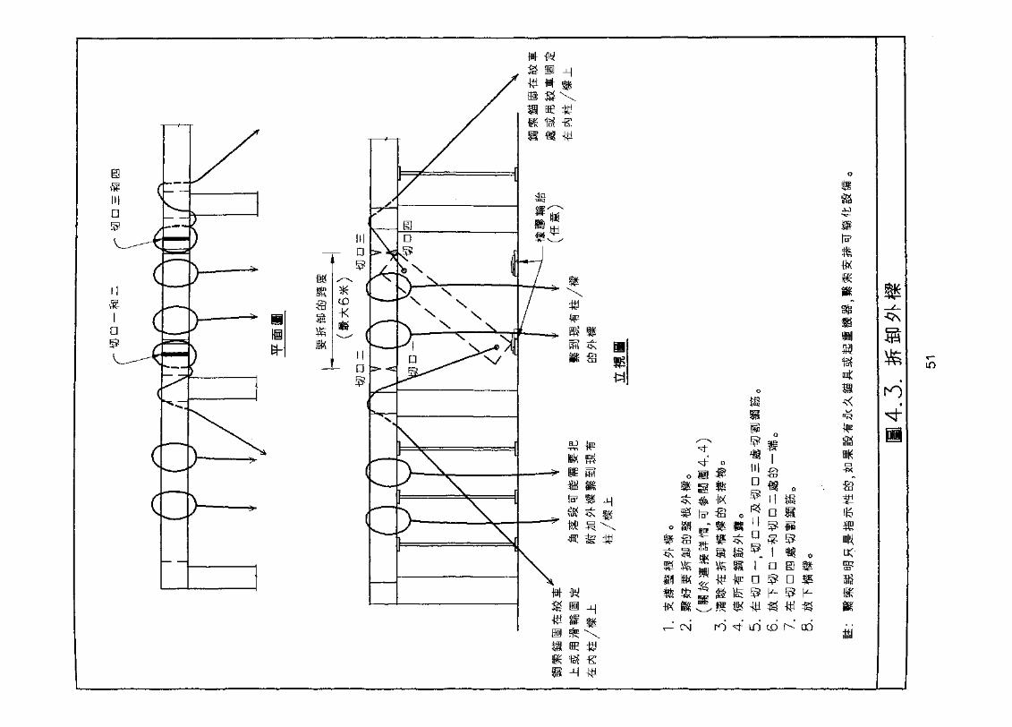
O jtfltai -a^r- TJ-I
m>< i , -c ) F<c n^ jH7 <n o , UIXot * *k- ID* I R* «e 5S R ^S * o: D &-4i } - j j i Hfe— "s?\ rpr
Vfji' Vrfi" -t"R -V1 1
^ *
4Kro
I a m nn ^ n m^ V- S K-
LO cd K GO
TO
fl*Kfig
US
is
*
-ON

01ro
out*czr
nun-Ht:
iff
m m
®
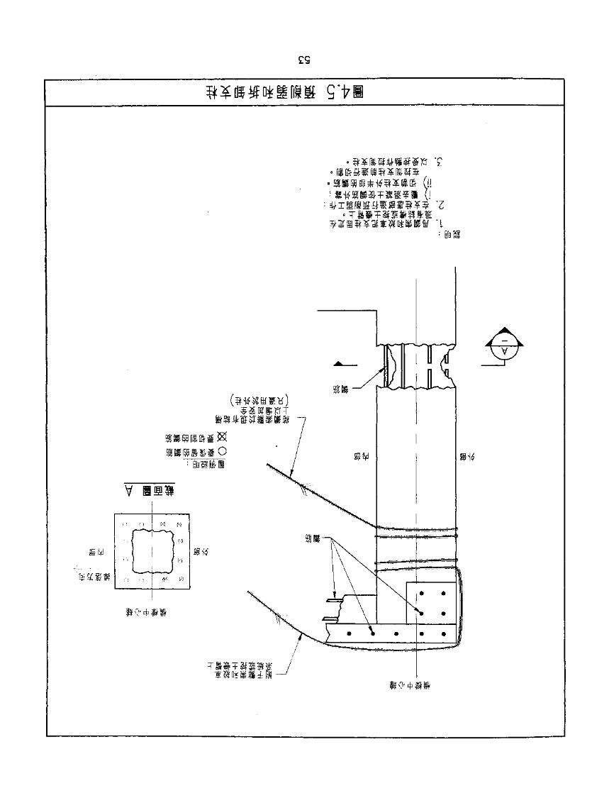
S'f I
~T7
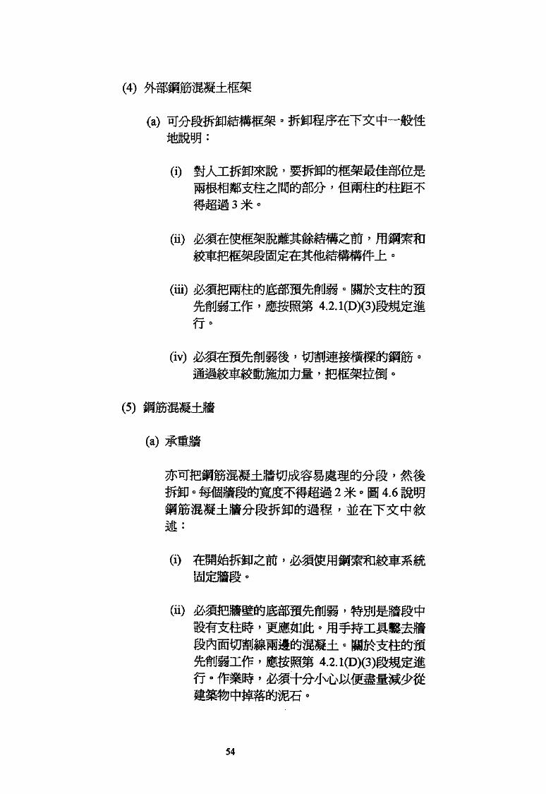
(4) «
(a)
(i)
(ii)^
(iii)
fT
(iv) iES
(5)
(a)
4.61
(i)
(ii)
4.2.
54

CD
BBS.
en
**»»jS$»ig*«&m^
3-iffliH '
H
(iii) '
(b)
(E)
m '
(2)
4.7 i
J& '4.8 i
56
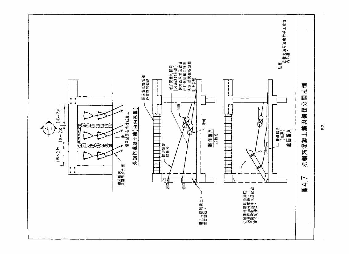
i
to
-H
is
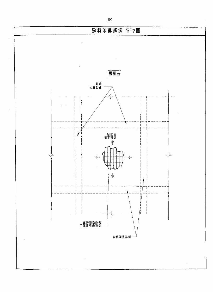
(l) •
(2) H 4.9 i
(G)
4.2.2
(A)
4.2.
(1)
tm •• :
(a)
59

09
6>
0*
X /
\ N
0(&
$$:§$
L _ _ _
r" 1 ] | r
•'' I|L_
J
n
1_J-L:X
5"9
7' I

*
-fH
•Hjnc
ion
o
Z9
m * (I)
(a)
% •
(£)
m • < t
*•
ni (q)
(3)
(4)
(5)
(C) 1
5.3
> Hlfc§1
(i) ' WIS
(2) - B 4.12
(3)>
63

-Ht! *
Dtti
to
m-H

m.
4.11.
65
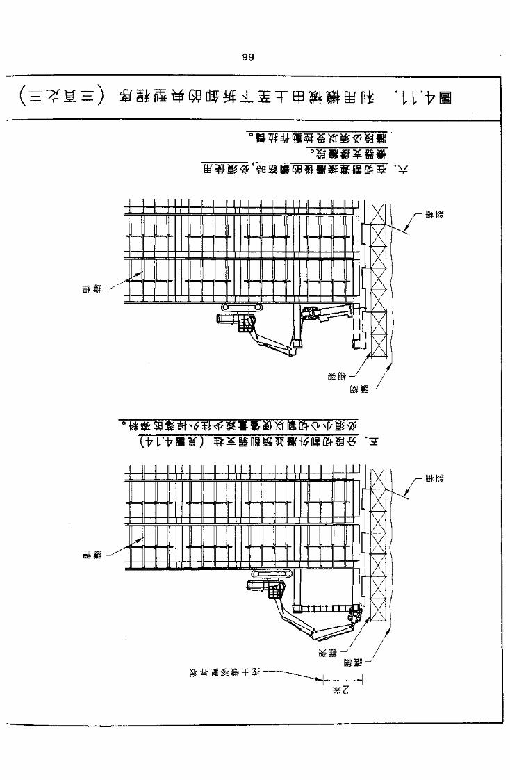
99
Tl/t
H
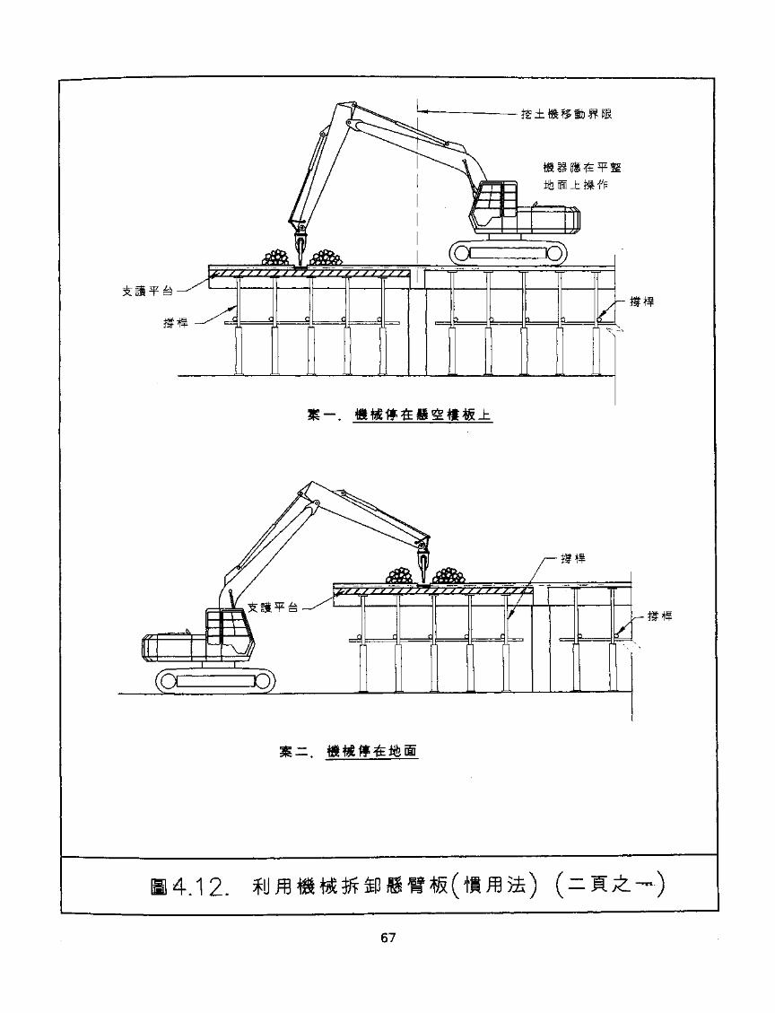
4.12.
67
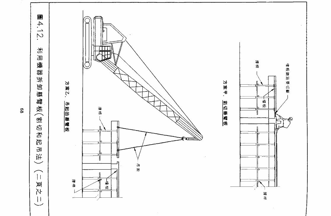
N3
0>00
N-
-ffl

(4)° >&
(5)
(D)
300
(a)
ap(£i?j|&!lli
4.2.2(0X3)
(a) i
(b) 4.2.1(0X3)
(c)
(d)
69
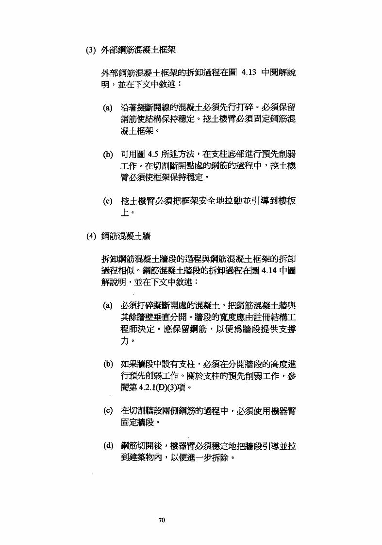
(3) #81
(a) ?
4.13
(b) 4.5 m^t^
(c) J±-
(4)
(a)-
'
(c) >
70
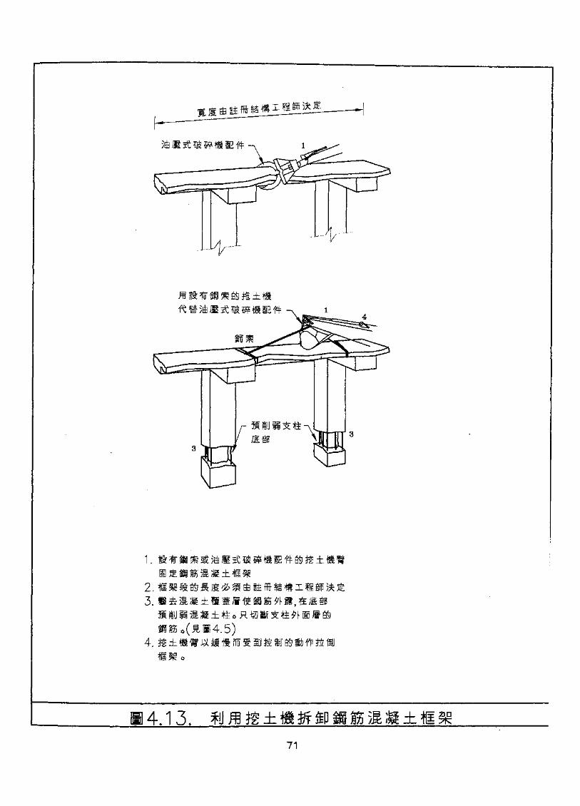
fiiyii^ttJ195 \i
2.3.
4.
4.13.71
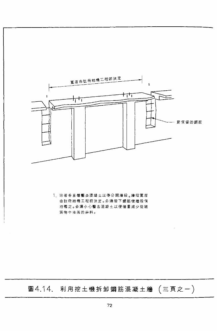
i, ;i ± Jj(
4.14.
72
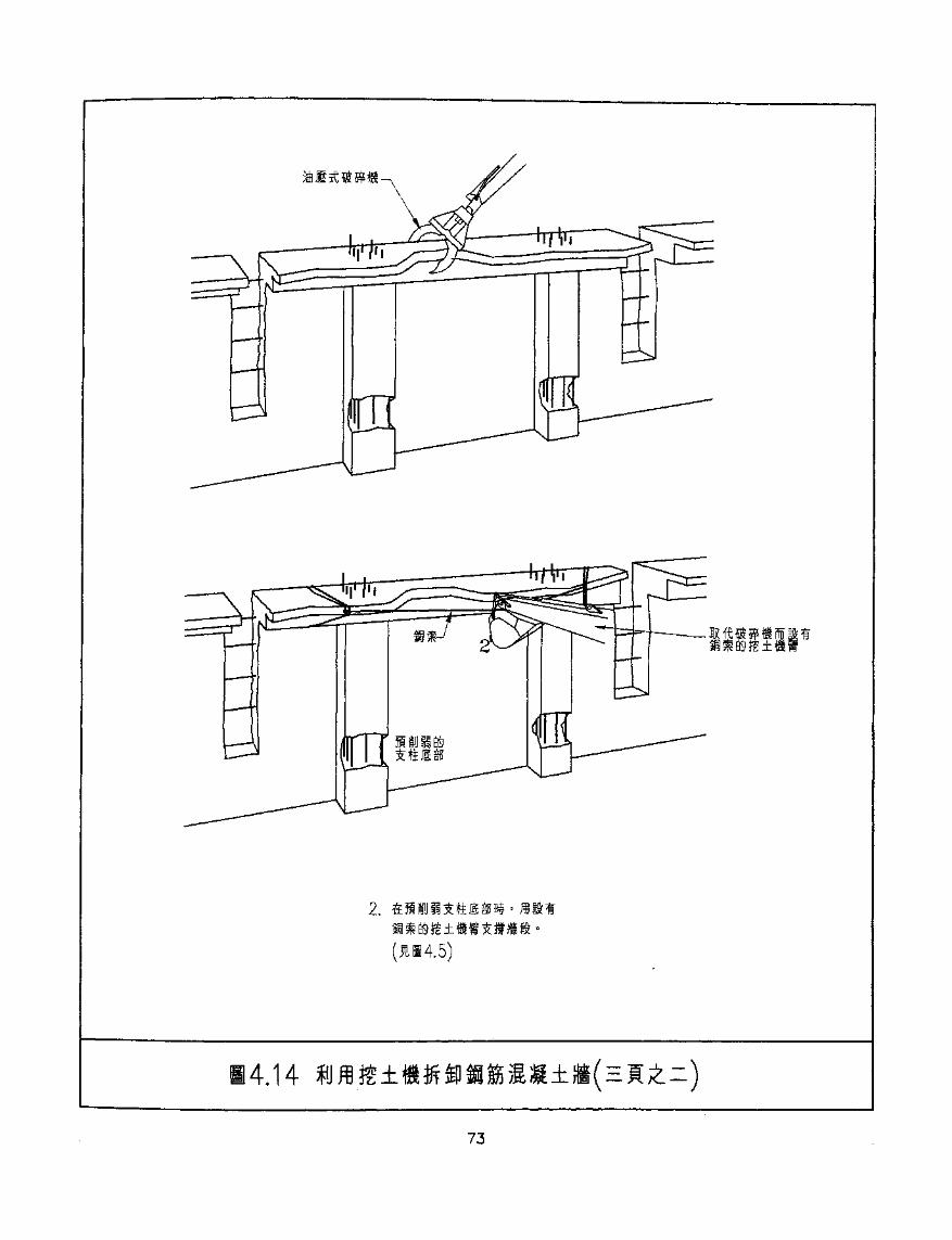
2.
;4.14
73
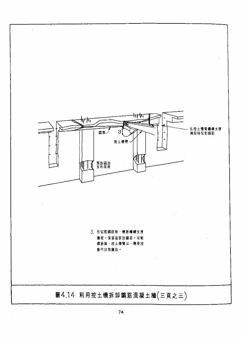
3.
74
(E) fflfc
4.3
>
' *
j?' mm 4.2.i(EtfMmxmm •
(F) ft#
(G)
4.3.1
•^fl&n3^a&-H4.15iJ
i »««*Slf« •
4.3.2
(A)
75
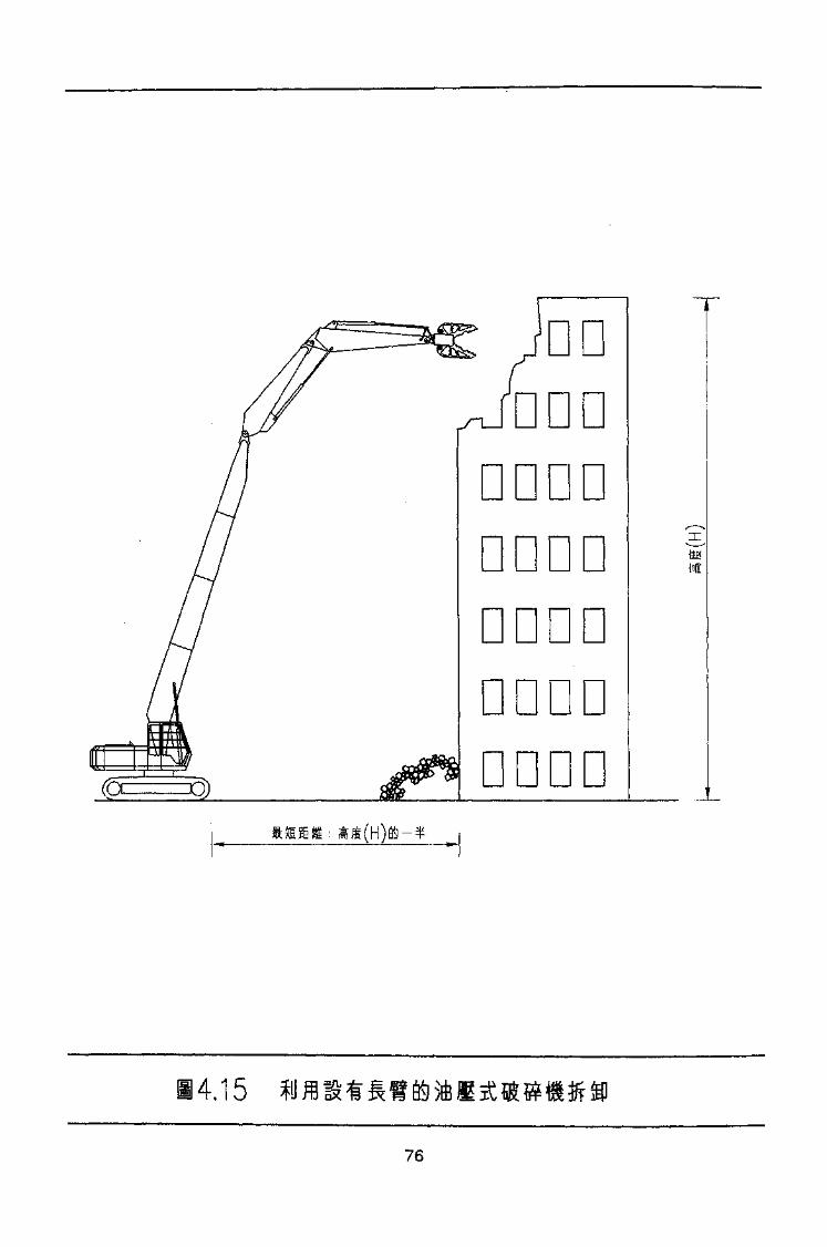
4.15
76
LL
* • '
•
• *
'
(o)
rr
^«4^(a)
M
-slz •• (apJiMO iqqi^S^±
vlz^ fiMS •o
dz • < IF« -^dz^S^WIka^ (a)
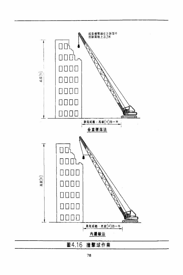
-Iffi-iif
DDDD
DD
nnnn
14.16
78
4.4.2
i(A) &
(B)
-
f «
f
(C)
-
^fl^ffiBW»fmtg •
ii 3
(D)
(E)
&m
(H)
79

a)± '
(J)(K)
•
•
(L)
(M) pPT»i!6
(N)»
(O)-
4.5
4.5.1
S •80
ff- •
4.5.2
(A)
(B) > fc'
rM3&i
(C)-
(D)
(E)-
'•
81

/T\ f>/ SxS&x\t±2 .TE3B5t^t.5(l) 4&glrpll7E -yi^/SB
(J)
(K)
(L) W MJ.
(M) :
(1) JliStlM^ffiTO^WF
(2)
(a) »
(N)
82
L\'V
< •m$
-
« • w
T
m *
•
(a)
(D)
•^ « (a)
(V)
3td-
•v
(0)
(a)
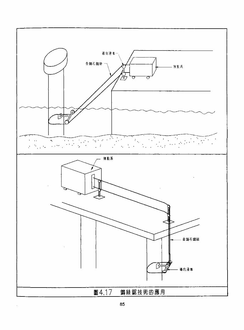
.4.1785
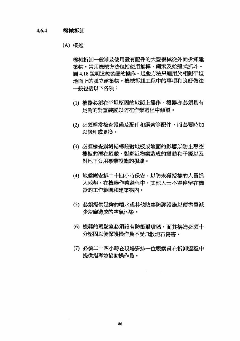
4.6.4
(A) mm
4.18 -
(i)
(2)
m(3)
(4)
(5)
86
M5H
-K
^LLO
¥
fill)
> 0.5H
00
4.18
(B)
'
(2)
'
(3)
(4)600 ^ -
(Q
T :
(2) 'If
88

68
(a)
(6)
(«)
(9)
•
(e)
fe)
'' (T)
(a)
si
(1) '
(2) r i
(3)
•
4.6.5 ftl
°C •TMlf '
(A)(B)
(C)
^^ 2,000 4,000°•
4.6.6
(A)
(C)
90
s VFJ* T\
5.1
P1
5.1.1
•
5.1.2
• f•
*
(A)
(B)
' ^lU^^tfiir^ffiJ-
(C)
'
-
91

(a.)
(b.)
92
£6
• figieK^H$TOkirrs
0
rs
•*
'
(v)
raiIk^$Nfe«[HlllBUlU < jr g^ l
I. no
«
rrs

(A) HH
PI
P3
(B)
Cl
C2 ci Pnpii '
——*| /^o I f "fffyRj vo pnS. *
'
(2)
-smffi^mm
94

•
'• WPS Id (I)
'• «
(D)
:
' 4»!
(e)
4i rs
M^mm^ ssns.'Upy:4
(v)

•y \v
'v' '**^
sssssss
s,sss
3
• 5^
___i_*»-
\\\\
oCDr-Oi
CDO
1^1-
' ^
•
f\
1. •5 *
. <M
-R
coCTJ
-H
43

' ' n• »
'•
'•
P2
• '
PI
(3) P3 n;
' Mf J•
'
C2 ±f
(B)
(1) Cl
97
86
(p)
(q)
(e)
(P)
CO
(q)
(l)
'

(e)
(4) C4 p°ni|:
• '
- ffiu
(C) : Sffe
(1)
(2)^^ '
(3)
99

5 ••
53,1
(A)
(2) °
••
(2)
(C)
(1) 1(2) I
5.3.2
(A) --
(B)
'
100
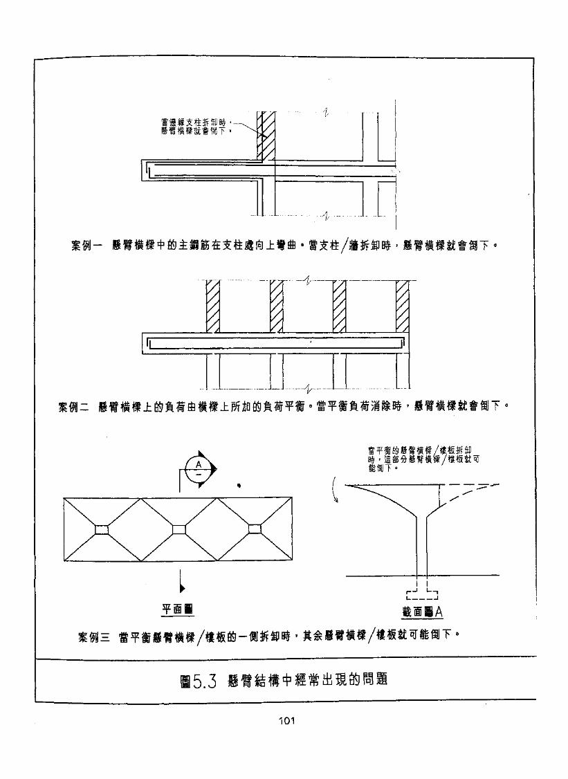
II
L iVrfe -K rh *tt
1
m —f J. AA A.
I
tt
^ v ~~ •
•
A__V
w^s; ft 1 1 IT
i?«f • ^a, -i± *}M E6* n
I(1
I 1
,5.3
101
ZOI
«
•illJkift^
«
irs
CD)
(9)
°
rrs
£01
- -
y^t-TJ/w
i; < y
l'9'S
' 9'S
• i*
(o)
^*SWIf38i*C&ai£
•®f .
(a)
(v)
rs-s
*®r*S
>
5.6.3
(A) > ^M
(B)
;
^«igP3»i StfL^mA/TppimO* JSK rpffp
5.7
(D) '
5.7.1
I?^^ffi-MS^^SrfiSnRn^l»ia^ '
im-^^^ '
5.7.2
m ' 4104
tfer HED;<3-
(£rm
/.LU4 ^ f H -J
^^%^hr
« it /J-U4V
H n^Jn IE
^9*
m wS3Q|
00
£ FT
H- :~nT
uii mm®
H
H^
in*~V. flt"HI —•" I
[+ IS S ufj 1+
•K -T! H - !
(H'"*t V
uti >v
all
-a*
is
Cft
u
w N-3-
^^ m-H
)i B - J n$ 3r
™f Cu (5- w " ^

5.8.2
5.8.3(A) W
(B)
(D)
T 3 |
106
LOl
<
SSf^M^^S^'' W^tt^
(a)
•
<MSiMzJ3f?3nfe£-J/
It» (V)
m •
6'S

(D)
43 o
(E)
5.10 f5.10.1
nw
Jth
5.10.3
m •
(A)
M '
108
*» ' •
(C)
CD) f
± •
109
6.
6.1
o'
no

Ill
Ill
n
* mwm.*« :
*
-
in««*
n
I'T
1.3
D
n
n
1.4
D
1.5 Ml
n
1.6
D ^
'
n
n
nn
m113
1.7
D '
n1.8 III B)
1.9
nnnnn
1.10 E&j
nDMS5I
2.
n
D -( -
D
114
SIT
oi R-foHtf
n
n
¥ n
• * < n
D
n
D
n
n

911
n
' n
D
-
nn
- «-^ .
'
3.
D
4.
n >
n ' > mi*
n
D
p
>
D
D
117
811
n
-
n• M 117 - F Zl^/jC JU-r B9 IP ^^^T*P6
n-9
D
D
<f - HOT r-i^F-qpd^y I—I
6TT
'01
< m
nn
'6

CTIT
rn.nullPJ
H-
* 5S/5
mill3<-Vhmeton
XB $t I i \ I ^ -
.ffi N-TTT jffll 4B- rn} <=:h
n>
^ »H^
1+
amcron
fflff -
H
v jUT
nunP4
U-
,-ffl-
/I—-v-
or
m \ 3531 -fraft C^T
*——* " ^>ssm
(9)
, (3)
•(a)
(o)
^ (9)
ii i? SfeJ^^feJ*^^ 8(v)
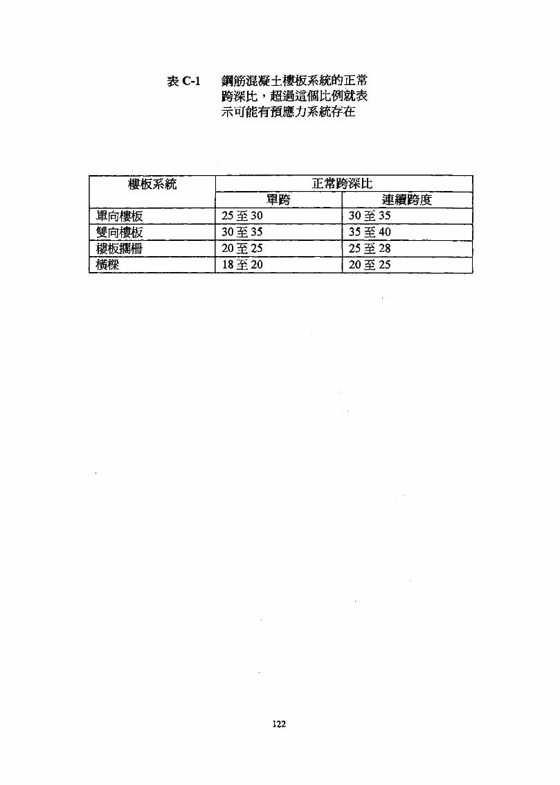
C-l>
25gg3030M3520S2518M20
30gg35
35gg40
20M25
122
jLr** A-*r? —r-* 3Cff • / * IHf & vjuSfflJXSWBte
2.
JW
(i)
(ii)
(iii)
(iv)
(v)
(vi) 1
123
it!
\ AEP*r >J— L y
it!
(vii) m n 75 : ffi& *
(viii) E o
(ix) iiffl}^^©^:175; ata
(x)
(xi)
6. Jr
(i) ^Sr^^(ii) ^^/5^
(iii) iJ
(v)
(vi)
(
123
(vii)
3.
(ix) *
(0
(ii)
(iii)
mm•>
(iv) (i
mm •>(vi)
(ix)
(x)
(xii) (£^;
mm •>
(xv)
4. &mm * iWfjX: >
124
5.
6.
m(iii) HI
(iv) (-.
> •,:
(v) ( -
(vi) (-
(vii)
iJ ( - ^irj ) ;
(i) i
(ii) ' 1
a) m&fWJ;
(iii) iS
125

911
mm owe
i Of?)(!)
feSi •^'
0
' &%'&£&•' < mw*mmm
•iHtr ' • J}|?»w5^^d$ir
aikJJ^ffl
n^iiffl^w^^^^i
5 SM~T^f. raXi!
'
6.
(A)
(B)
(Q
(D) ^ft]
(E) £
r»pxfi^j^
7.
1900 M 0700 ' M-1900 flf ' »
) ' wm 0700^^XfMSIS
127

8.
9.
10.
:
A -
0800 - 2300
- 2706 88880800 - 1800
FUl -267465050800 - 1800
-24724382
B-
0800-2300
H - 2706 8888
128
1.1.1
1.2
l.l .l H F 1
1.1.2 fflF2
1.1.3 ffi F3
1.1.4 m F4
1.1.5
1.1.6 HF6
1.1.7 m F?
'
1.2.1— TL/
1.2.2
1.2.3
2. ffi&2.1 mm
2.1.1
2.1.2
2.1.3
J/f-
A ft] B
129

0£l
I'l
VYl

B VT
9T tT 31 OT 9 9 t *J
\
0^-9+
L v,«V
CT)
i • : r-> r> • p.c^^'a 9
GT T T
n
^ ^--1
J^
IV)
i t
a
"fl *9L

mm
2.2.1 Si2.2 Jfe«B«
2.3 iSW«
3.
ffi:2.42.52.6 J
qTHS3.1 j3.2 J
4. ^54.1
4.2 JK55
4.3(A)
(B)
(i)(ii)
(iii)
IFJ.A132

LDi
LOi pqI
OQ
3:U
IC/3
iGO
CO
ICO
sIen
COPQ
CO
-L.
™
-
4Q
m
I-M
W-H
CN
10
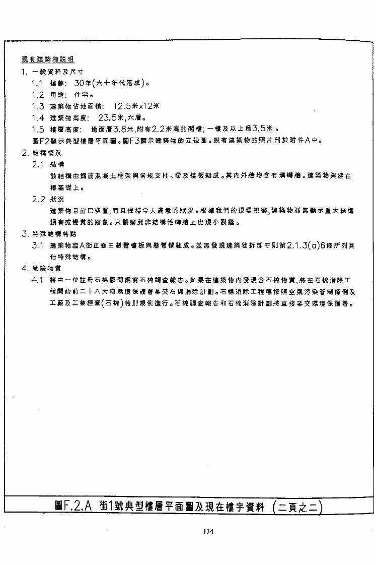
1.1
1.21.31.41.5
2.
3.3.1
4.4.1
2.1
2.2
2.A134
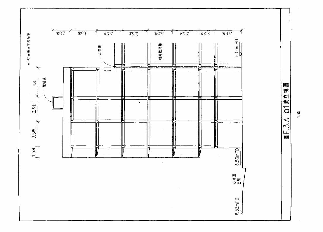
Usm
QQ_
E
LO i
ro
.-J
Q
EroLO
cd
CO
in

1.1.1
1.2 ^5
1.3
136
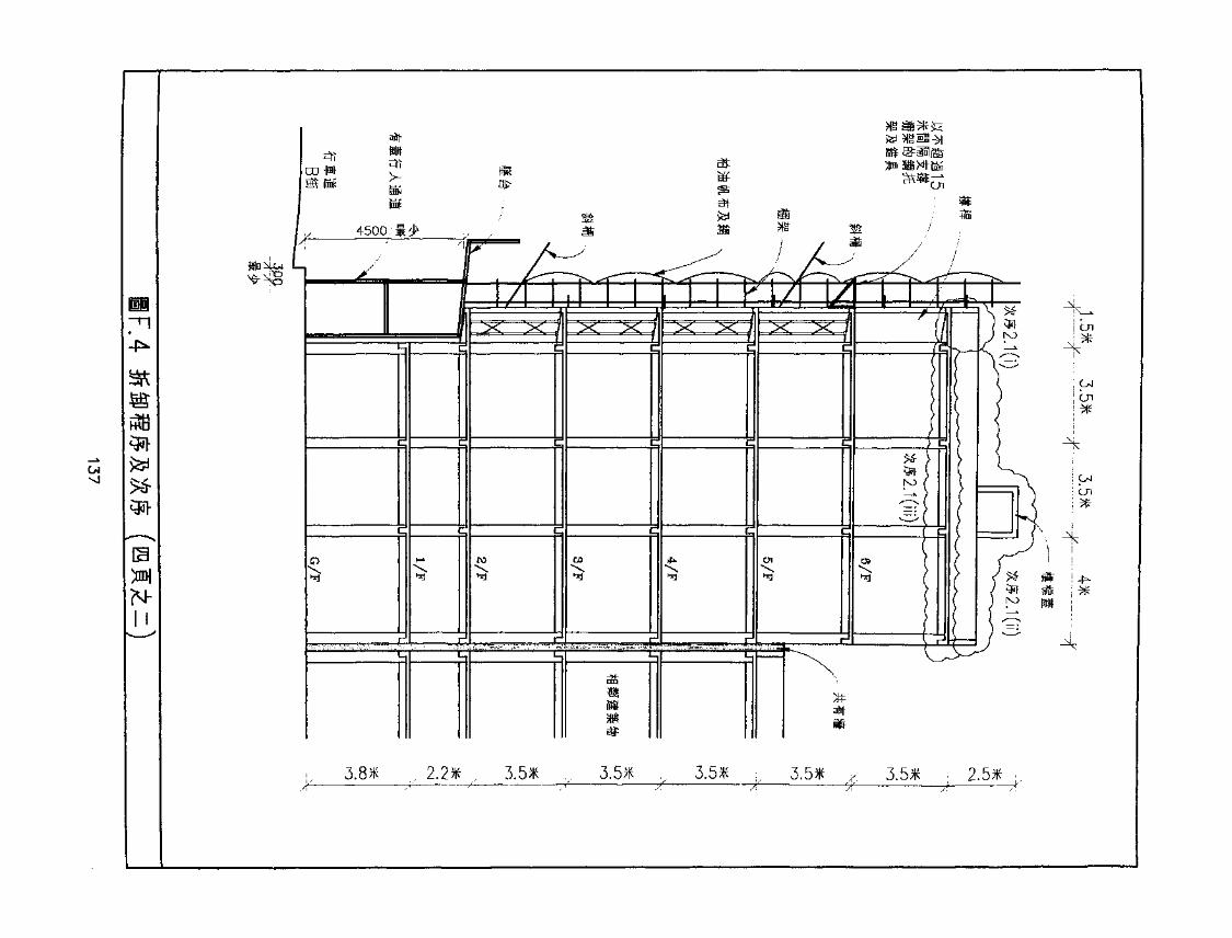
-£-
m
N-
atfj-
it
3.8* ,f 2.2* : , 3.5* > 3.5* ,, 3.5* ;, 3.5* r; 3.5* , 2.5* <.,
uqro
LO
LO
00ro
unro
toro
LO
G>

140
1
&WS
LO
LO
LO
LOro
LO
LO
ro
CN
o
.5 863141
2.
3.3.13.23.3
4.
5. >5.1
if
5.2
5.3 ±
(A) 5l
(B)(C)
5.4
6.6.1
6.2(A)(B)
a
'.5
142
6.3(A)
(B)
6.4
(A)
(B)
6.5
7. il
7.1 R
7.2
7.38. RjfeS
8.1
8.2
8.2.18.2.28.2.3
9. KSP9.1
9.2
9.39.4
143
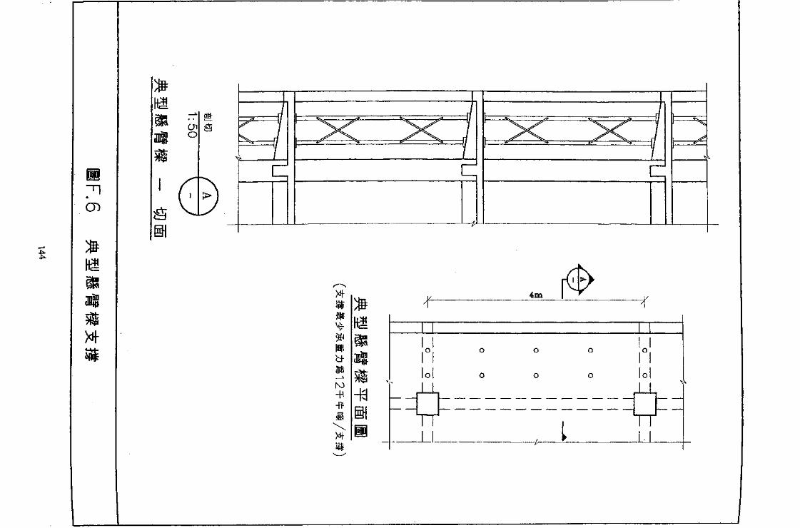
71CD
eno
El
CZ
Xfrm
ro-H

1u 1500 I 1500
3500(fi) 152X89X23.842; /f/*[@1500
'.*"-'.*
i--h-
152X89X23.84£/f/*[ffS«- iDlMSlS1»±«-111AI
V
152X89X23.84f>/f/f[ ,©1500
/y
//
SBX*«I*J
-152X89X23.84fi/f/*[
2.
3.
T
IF.7.
145

9T.Z-
STZ
: m-
9 n* s
I'Ht T -«•» I
°(93) 99 ffl 9TI
179
to
STI
v n
£TI
Zl'l
ITl
? ri

IN
o(N
1:500)
CD 9
CM
LO
d
7.4mPD
21*
7.4mPD
CN
H^-7 ,4m pjp
-4-7.4mPD
XXSi
7.4mPD
7.4mPD
G.T.147

mm
2.
2,12.22.3
fift: 21*x16*
ffi:2.4
2.52.6
3.3.13.2 73.3
4.4.1
4.2
4.3
26^ B3
148

5• -x* »
6
I I 11 —
4
f—T
S-A3
S-A4
r
S-B3
S-B4
S-D3
S-D4 S-E4
r
S-F3
S-F4
S-H3
S-H4
r
LO
i
in- » !
10
3.5* 3.5* 3.5* 3.5* 3.5* 3.5*
149
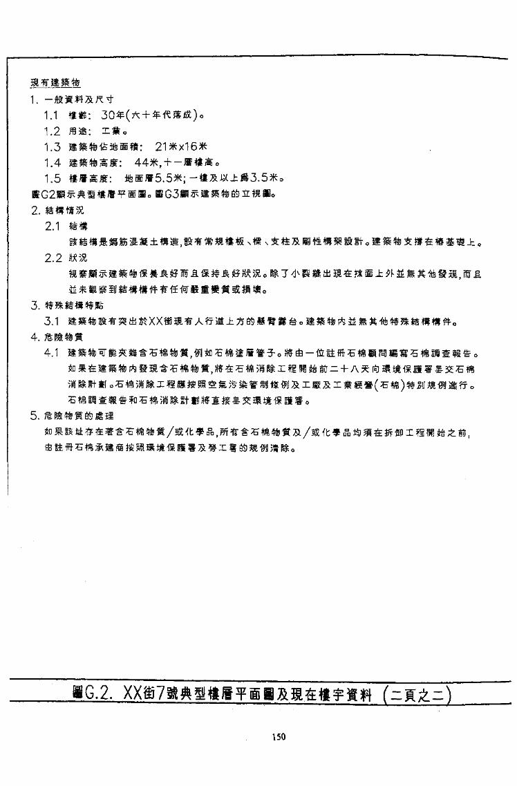
1.1
1.21.31.41.5
2.2.1
2.2
3.3.1
4.4.1
5.
.2.
150
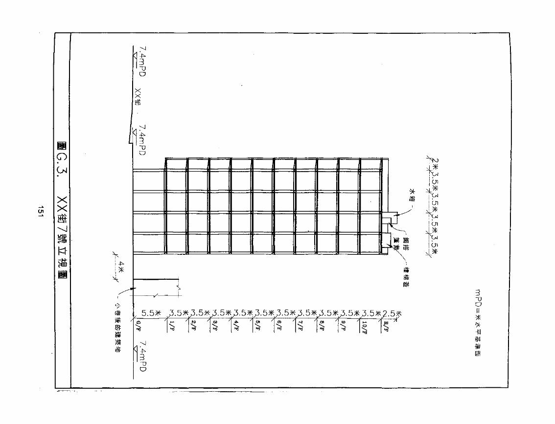
en
p01
XX
o
XX
V14-
*
3'~DO ^M
*
-V- -oO
5.5* ^3.5*^3. 5*^.5*^3. 5*^3. 5*^3.5*^3.5*^.5*^3. 5*^3. 5*^. 5^
-K
3"DO
*
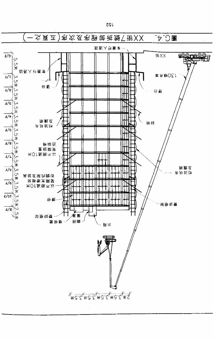
( - ) . ff . % .; % if a di jiE »£ •% XX rfr ' 9
J/T
cncn
Cn
cn
i/Ccn
cn
d/Sn
J/9Cn
Vcn
cn
Vcn
I/OT
Cn
>ocn

2*3.5*3.5*3.5*3.5*^-—^ -ft- -~^~ - -X— — -7
0,4;.153

7 F a 6 F
I *3,5*3.5*3.5*3.5*—x £_—^ -f——^
"• J
inLO
R/F
10/F
9/F
B/F
7/F
6/F
5/F
4/F
3/F
2/F
l/F
C/P
GA..154
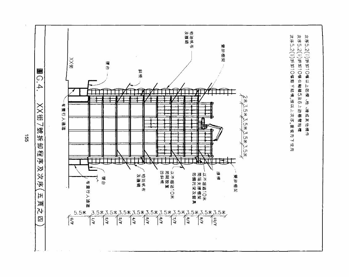
en
o
XXm
wo
M- 5.5* _3.5* 3.5* 3.5* 3.5* 3.5*^5.05
01 en enINJ k) k)
o o o
1
s
CD d
h- !
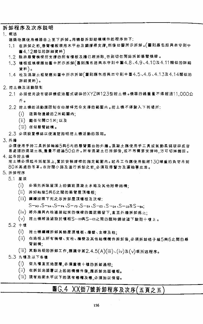
1.
1.1
1.21.3
1.4
2.2.1
4.5 v4. 6x4.1 3X4.1
2.2
(i)
(ii)
(ill)2.3 ^§!
3.
4.
5.5.1 MIS
(i)(ii)
(iii) ' -S—H3 \S~H4 \S-F4 \S~F3 \S-E4 \S~E3 \S~D4 \S
(iv)
(v)
B4j
(i) • • .(ii)
(iii)
156
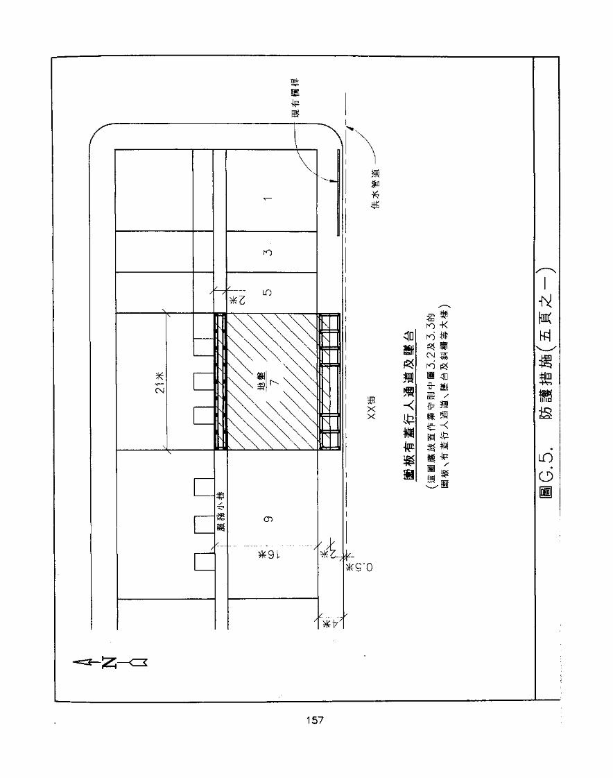
it""ST
IP
*z_.^
afin*•£
BXX
ro -K
^ Sro fS<
fr Siroc /te-rnm «
K
in6
157
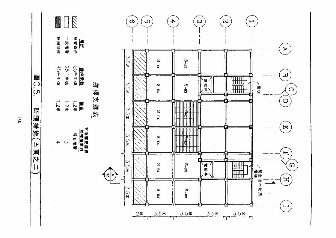
00
pOr
-M-II
n&
-f^ K) rocn cn cn-H -H -H-fr -fr H*
S
K) hO COXH-
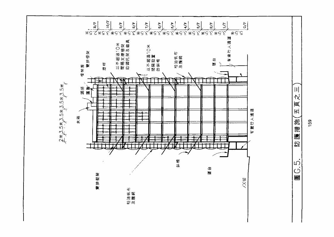
LO
^
LO
LO
LO •
fr,
CO r^- «o s-
4DK-
5U
crnrrrm rTTTNTrrr
m
u?
-r^
im
LO
O
O)in
2.
(A)
3.
(B)
(c)«ss(A)
(B)
(c)
(A)
(B)
(c)
(D)5. j'g^
5.1
5.2
(A) >/
(B) 5I
(c)(D)
6.6.1 Sffet fan
.5
160

6.2 KA'
&&*a
6.3 it HI
«Eb(A)
(B)
6.4
(A)7.
8.
7.1
7.2
7.3
^f^8.1
8.28.2.1
8.2.28.2,38.2.4
9.9.19.29.39.4
161
162

HK 690.260289 H77Hong Kong (China). BuildingsDept.Draft code of practice fordemolition of buildings
Date Due |~^P:7r V. '' .^" ' ' ~*
rBFn'd'in'g- H i ..
N
]
r\f^ T'r>Tp | /{ iJI ^{jl^ LAJ
» «t •> , ..^N
•'