Embed Size (px)
Citation preview
Preview
THE UNIVERSITY LAB: CONCEPTUAL DESIGN
The pieces of the database design puzzle come together in this appendix and Appendix C,
The University Lab: Conceptual Design Verification, Logical Design, and Implementation.You
will develop a conceptual database design by using the ideas and techniques presented in
Chapter 4, Entity Relationship (ER) Modeling; Chapter 5, Advanced Data Modeling;
Chapter 6, Normalization of Database Tables; and Chapter 9, Database Design.
You will see the evolution of a database system, starting with the results of the database
initial study and moving through a conceptual design’s initial ER diagram. In Appendix D,
Converting an ER Model into a Database Structure, you will see how a conceptual design
is evaluated and transformed into a logical design that can be implemented in any relational
DBMS environment.
B
AP
PE
ND
IX
45222_AppB 9/25/2009 12:40:48 Page 1
Many years of teaching database design have taught the authors a valuable lesson: If you have never stepped througha complete example of database design, chances are that you will not be able to successfully design and implement adatabase system.
“I hear it and I forget it, I see it and I remember it, I do it and I learn it.” —Old Chinese proverb
The example will be the automation of a large university computer lab. Because the design detailed in this appendixis based on a real project, you will confront a few real-world problems and develop some important analytical skills.
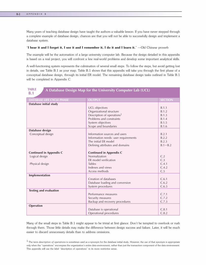
A well-functioning system represents the culmination of several small steps. To follow the steps, but avoid getting lostin details, use Table B.1 as your map. Table B.1 shows that this appendix will take you through the first phase of aconceptual database design, through its initial ER model. The remaining database design tasks outlined in Table B.1will be completed in Appendix C.
TABLEB.1
A Database Design Map for the University Computer Lab (UCL)
DATABASE LIFE CYCLE PHASE OUTPUT SECTIONDatabase initial study
UCL objectivesOrganizational structureDescription of operations1
Problems and constraintsSystem objectivesScope and boundaries
B.1.1B.1.2B.1.3B.1.4B.1.5B.1.6
Database designConceptual design
Continued in Appendix CLogical design
Physical design
Information sources and usersInformation needs: user requirementsThe initial ER modelDefining attributes and domains
Continued in Appendix CNormalizationER model verificationTablesIndexes and viewsAccess methods
B.2.1B.2.2B.2.3B.1−B.2
C.2C.3C.4.1C.4.2C.5
ImplementationCreation of databasesDatabase loading and conversionSystem procedures
C.6.1C.6.2C.6.3
Testing and evaluationPerformance measuresSecurity measuresBackup and recovery procedures
C.7.1C.7.2C.7.3
OperationDatabase is operationalOperational procedures
C.8.1C.8.2
Many of the small steps in Table B.1 might appear to be trivial at first glance. Don’t be tempted to overlook or rushthrough them. Those little details may make the difference between design success and failure. Later, it will be mucheasier to discard unnecessary details than to address omissions.
1 The term description of operations is sometimes used as a synonym for the database initial study. However, the use of that synonym is appropriateonly when the “operations” encompass the organization’s entire data environment, rather than just the transaction component of the data environment.This appendix will use the label “description of operations” in its more restrictive sense.
45222_AppB 9/25/2009 12:40:49 Page 2
B-2 A P P E N D I X B
Database design is “detail” work. The details in this example should give you a better grasp of a design process thatsometimes appears to be disorganized.
B.1 THE DATABASE INITIAL STUDY
The database initial study is basically a detailed description of an organization’s current and proposed database systemenvironments. Therefore, the database initial study must include a careful accounting of the organization’s objectives,its structure, its operations, its problems and constraints, the system’s objectives, the system’s scope and boundaries,the information sources and users, and the end-user requirements.
A real-world database initial study is likely to have hundreds of pages because detail and accuracy are essential. Theneed for such detail and accuracy is obvious when you realize that the database design is based on the business rulesderived from the database initial study. If the database initial study lacks detail and/or accuracy, the business rules arelikely to be incomplete or inaccurate. It follows that the database design based on such business rules is destined to fail.
The information contained in the database initial study is, to a large extent, the product of interviews with key endusers. Those people are the system’s main beneficiaries and must be identified carefully. The key users of the UniversityComputer Lab application developed in this appendix are:
� The assistant dean (dean) of the College of Business.
� The computer lab director (CLD), who is charged with the Lab’s operational management.
� The computer lab assistants (LAs), who are charged with the Lab’s daily operations.
� The computer lab secretary (CLS), who assists in the Lab’s general administrative functions.
� The computer lab’s graduate assistants (GAs), who work under the lab director to provide technical support andtraining to faculty and staff using the College of Business resources.
In the interest of brevity, only a few excerpts of the numerous interviews that were undertaken for this project willbe shown.
B.1.1 UCL Objectives
The University Computer Lab (UCL) is in a central location on campus and is accessible by all university studentsregardless of major. The UCL provides access to many resources, including 200 computers, laser printers, andscanners, to all university members. The UCL provides service and support to a group of users composed of faculty,staff, and students. The Lab’s objectives are to:
� Provide users with controlled access to the UCL’s assets, such as microcomputers, printers, supplies,application software, and software documentation.
� Guide users working with the UCL’s assets and provide general problem-solving services. Those services areprimarily designed to help users with basic computing operations, such as disk formatting, file copying,(approved), software installation, and basic startup procedures.
B.1.2 Organizational Structure
Understanding the UCL’s organizational structure helps the designer define the organization’s lines of communicationand establish appropriate reporting requirements. (See Figure B.1.)
The computer lab director (CLD) manages all of the UCL’s operational functions. The CLD is assisted by the computerlab secretary (CLS). Graduate assistants (GAs) and undergraduate students work in the Lab as lab assistants (LAs). TheCLD reports to the assistant dean of the College of Business, who reports to the College of Business dean, who, inturn, reports to the university’s academic vice president, who reports to the university president. Although most of theuniversity’s chain of command for the College of Business is shown in Figure B.1, the design will focus exclusively on
45222_AppB 9/25/2009 12:40:50 Page 3
B-3T H E U N I V E R S I T Y L A B : C O N C E P T U A L D E S I G N
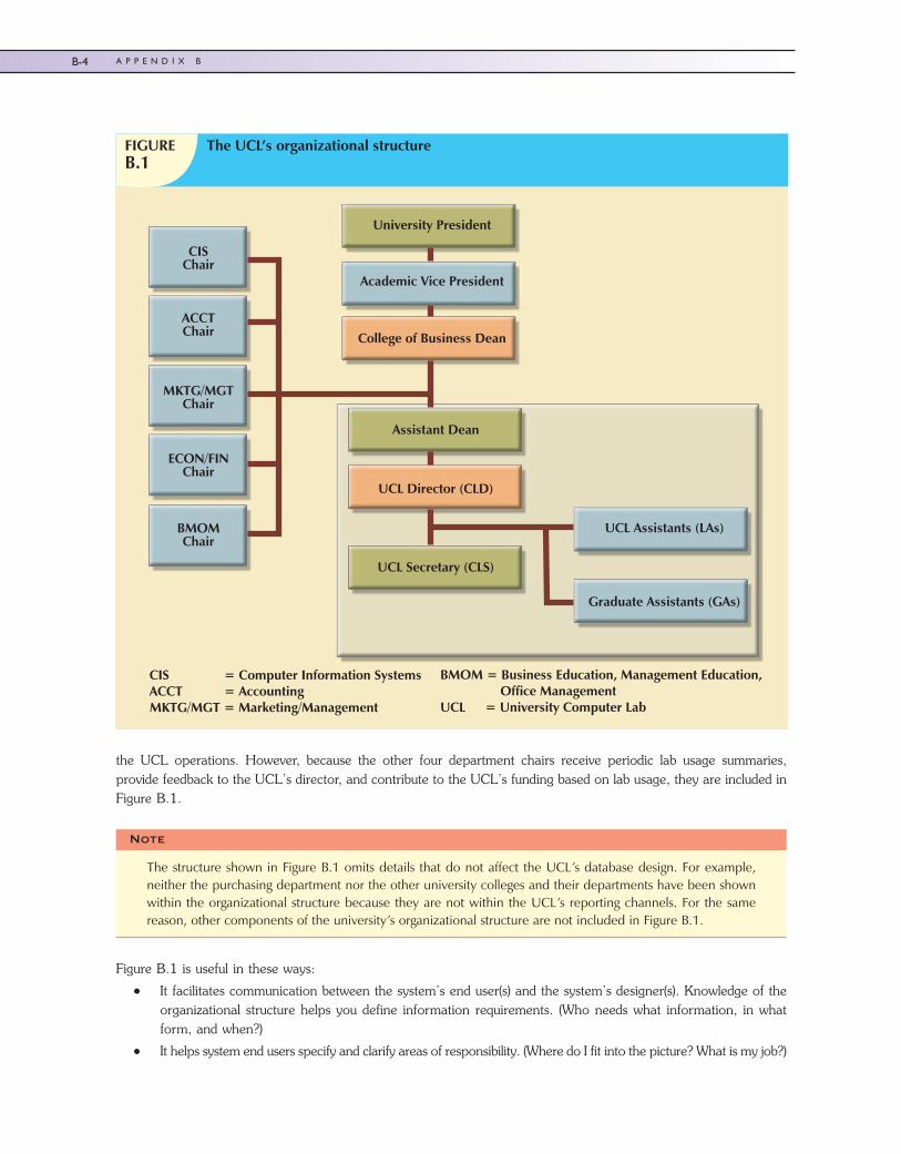
the UCL operations. However, because the other four department chairs receive periodic lab usage summaries,provide feedback to the UCL’s director, and contribute to the UCL’s funding based on lab usage, they are included inFigure B.1.
Figure B.1 is useful in these ways:
� It facilitates communication between the system’s end user(s) and the system’s designer(s). Knowledge of theorganizational structure helps you define information requirements. (Who needs what information, in whatform, and when?)
� It helps system end users specify and clarify areas of responsibility. (Where do I fit into the picture? What is my job?)
FIGUREB.1
The UCL’s organizational structure
University President
Academic Vice President
College of Business Dean
Assistant Dean
UCL Director (CLD)
UCL Secretary (CLS)
UCL Assistants (LAs)
CISChair
ACCTChair
MKTG/MGTChair
ECON/FINChair
BMOMChair
CIS = Computer Information Systems ACCT = AccountingMKTG/MGT = Marketing/Management
BMOM = Business Education, Management Education, Office ManagementUCL = University Computer Lab
Graduate Assistants (GAs)
Note
The structure shown in Figure B.1 omits details that do not affect the UCL’s database design. For example,neither the purchasing department nor the other university colleges and their departments have been shownwithin the organizational structure because they are not within the UCL’s reporting channels. For the samereason, other components of the university’s organizational structure are not included in Figure B.1.
45222_AppB 9/25/2009 12:40:50 Page 4
B-4 A P P E N D I X B
Knowing the complete organizational structure is important even when a system is designed for only one componentbecause the system might be expanded later to include other parts of the structure. The designer must keep in mindthat different departments might have different, and sometimes conflicting, views of the data and/or the systemrequirements. The job of the database designer is to develop a common and shared view of data within theorganization.
B.1.3 Description of Operations
Once the UCL’s objectives and organizational structure are defined, it is time to study the operations. The UCL hassix types of operations. They are organized as inventory/storage/order management, equipment maintenance andrepair management, equipment check-out and check-in management, lab assistant payroll management, lab reserva-tions management, and lab access management.
Inventory/Storage/Order ManagementThe UCL’s items are classified as hardware, software, literature, and supplies.
� Hardware includes computers, terminals, printers, and so on.
� Software includes all application programs, such as spreadsheets, word-processing software, statisticalsoftware, and database software.
� Literature includes reference texts and software manuals.
� Supplies include all consumables, such as printer ribbons and paper.
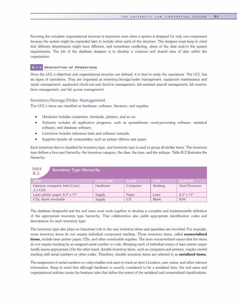
Each inventory item is classified by inventory type, and inventory type is used to group all similar items. The inventorytype defines a four-part hierarchy: the inventory category, the class, the type, and the subtype. Table B.2 illustrates thehierarchy.
TABLEB.2
Inventory Type Hierarchy
ITEM CATEGORY CLASS TYPE SUBTYPEGateway computer, Intel Core2,2.3 GHz
Hardware Computer Desktop Dual Processor
Laser printer paper, 8.5" x 11" Supply Paper Laser 8.5" x 11"CDs, blank rewritable Supply CD Blank R/W
The database designer(s) and the end users must work together to develop a complete and implementable definitionof the appropriate inventory type hierarchy. That collaboration also yields appropriate identification codes anddescriptions for each inventory type.
The inventory type also plays an important role in the way inventory items and quantities are recorded. For example,some inventory items do not require individual component tracking. Those inventory items, called nonserializeditems, include laser printer paper, CDs, and other nondurable supplies. The term nonserialized means that the itemsdo not require tracking by an assigned serial number or code. (Keeping track of individual reams of laser printer paperhardly seems appropriate.) On the other hand, durable inventory items, such as computers and printers, require carefultracking with serial numbers or other codes. Therefore, durable inventory items are referred to as serialized items.
The assignment of serial numbers or codes enables end users to track an item’s location, user, status, and other relevantinformation. Keep in mind that although hardware is usually considered to be a serialized item, the end users andorganizational policies create the business rules that define the extent of the serialized and nonserialized classifications.
45222_AppB 10/2/2009 8:32:16 Page 5
B-5T H E U N I V E R S I T Y L A B : C O N C E P T U A L D E S I G N
The inventory’s items are updated when:
� An ordered item is received.
� An item is checked out of inventory or checked into inventory by a lab user.
� A consumable item (such as paper or an ink cartridge) is withdrawn from inventory for use.
� The CLD must adjust the inventory. For example, if a physical inventory check reveals that a box of paper ismissing, the quantity on hand for that item must be adjusted.
University regulations specify that if a requisition is issued for an amount exceeding $500, a university-wide committeemust approve the purchase. Once approved, the requisition is sent to the purchasing department for bidding andpurchasing.
An exception to the generic rule is made only when an item is purchased under state contract. Approved items notpurchased under the state contract are sent out for bids. The purchasing department sends a purchase order to thevendor who made the winning bid. A copy of the purchase order is sent to the UCL. After receiving the item, the UCLissues a payment authorization to the university accounts payable department for payment of the purchase order.
When the item is received, it might be placed in the UCL to be used or it might be stored. There are several storagelocations; each can contain many different kinds of items, and each type of item can be stored in several differentlocations. For example, three printers might be distributed by storing one in location A and placing the other two inthe UCL for immediate use. Supplies are withdrawn from storage as needed.
Equipment Maintenance and Repair ManagementComputer equipment occasionally malfunctions. Defective equipment is usually repaired by the CLB. If the problemcannot be solved in-house, the equipment is sent to the vendor for repair.
If a piece of equipment requires maintenance, the CLD generates an entry in the Bad Equipment Log. If the equipmentmust be returned to the vendor for repair, the CLD makes an entry in the Hardware Returned for Service Log.
Note
Generic Rule
The university-wide committee requires the CLD to request items without specifying a specific brand and/orvendor unless the CLD can document compatibility problems. You will discover later that such a genericrequirement has an effect on the entity attribute selection. For example, you must define equipment byinventory type, as follows:
• Category: Hardware
• Class: Computer
• Type: Desktop
• Subtype: Pentium Dual ProcessorA sample requisition for the proposed purchase of five computers would be written this way:Five (5) computers with the following characteristics: Intel Core2 processor or equivalent, minimum
clock speed 2 GHz, minimum 1024 MB high-speed SDRAM, 17-inch LCD monitor, 64X CD-ROM drive,256 MB video memory, hard drive with minimum 200 GB capacity, 3.5-inch disk drive, 101 keyboard orequivalent, MS IntelliMouse or equivalent, 100 Mb Ethernet NIC, speakers, MS Windows Vista Businessand MS Office 2007 office suite included.
45222_AppB 9/25/2009 12:40:50 Page 6
B-6 A P P E N D I X B
Equipment Check-Out and Check-In ManagementAlthough the Lab’s budget and the general administrative responsibility are assigned to the College of Business, anyuniversity student, professor, or staff member can use the Lab’s facilities. The designer asks the following questions toidentify constraints:
Lab Assistant Payroll ManagementThe UCL pays lab assistants (LAs) on an hourly basis and keeps track of the total hours worked by each LA duringeach 14-day pay period. Each LA is assigned a work schedule (the dates and times each LA must work) and mustsubmit a time sheet (showing the hours actually worked) before a paycheck can be issued. The CLD reviews the timesheets and sends them to the payroll department for further processing. Graduate assistants (GAs) are paid a monthlystipend and work a fixed number of hours per week; they are not included in payroll calculations.
Lab Reservations ManagementThe UCL can be reserved by faculty members for teaching purposes. A faculty member fills out a reservation form toreserve the Lab, specifying the date, time, department, and course number of the class to be taught. If an instructorreserves the Lab for a small class, students not enrolled in that class may use the remaining unoccupied computers atthe instructor’s discretion. Appropriate questions here would be as follows:
Q&A
DESIGNER:
“May equipment be borrowed from the Lab?”
END USER:
“Only professors or staff members may borrow equipment from the Lab. In order to keep a record ofequipment location and use, the CLD must check out the equipment. The professor who wants to borrow theequipment must fill out the appropriate form before removing any equipment. The check-out form requires theuser to supply a date-out and an estimated date-in. If the equipment has not been returned by the date-indeadline, a notice is sent to the professor whose name appears on the check-out form. Student manuals anddata disks may not be borrowed; they are for use only in the Lab.”
Q&A
DESIGNER:
“Are limits placed on how often a faculty member can reserve the Lab?”
END USER:
“No, but given the Lab’s limited resources, this may be the time to define limits.”
Q&A
DESIGNER:
“How far ahead of time must the Lab be reserved?”
END USER:
“A faculty member must reserve the Lab at least one calendar week ahead of time.”
45222_AppB 9/25/2009 12:40:51 Page 7
B-7T H E U N I V E R S I T Y L A B : C O N C E P T U A L D E S I G N
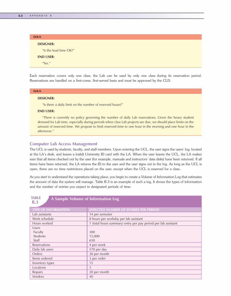
Each reservation covers only one class; the Lab can be used by only one class during its reservation period.Reservations are handled on a first-come, first-served basis and must be approved by the CLD.
Computer Lab Access ManagementThe UCL is used by students, faculty, and staff members. Upon entering the UCL, the user signs the users’ log, locatedat the LA’s desk, and leaves a (valid) University ID card with the LA. When the user leaves the UCL, the LA makessure that all items checked out by the user (for example, manuals and instructors’ data disks) have been returned. If allitems have been returned, the LA returns the ID to the user and the user signs out in the log. As long as the UCL isopen, there are no time restrictions placed on the user, except when the UCL is reserved for a class.
As you start to understand the operations taking place, you begin to create a Volume of Information Log that estimatesthe amount of data the system will manage. Table B.3 is an example of such a log, It shows the types of informationand the number of entries you expect in designated periods of time.
TABLEB.3
A Sample Volume of Information Log
TYPE OF INFORMATION EXPECTED NUMBER OF ENTRIES PER PERIODLab assistants 14 per semesterWork schedule 8 hours per workday per lab assistantHours worked 1 (total hours summary) entry per pay period per lab assistantUsersFacultyStudentsStaff
30015,000650
Reservations 4 per weekDaily lab users 570 per dayOrders 20 per monthItems ordered 3 per orderInventory types 15Locations 5Repairs 20 per monthVendors 40
Q&A
DESIGNER:
“Is the lead time OK?”
END USER:
“Yes.”
Q&A
DESIGNER:
“Is there a daily limit on the number of reserved hours?”
END USER:
“There is currently no policy governing the number of daily Lab reservations. Given the heavy studentdemand for Lab time, especially during periods when class Lab projects are due, we should place limits on theamount of reserved time. We propose to limit reserved time to one hour in the morning and one hour in theafternoon.”
45222_AppB 9/25/2009 12:40:51 Page 8
B-8 A P P E N D I X B
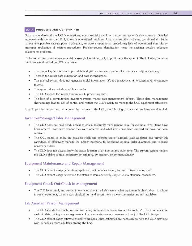
B.1.4 Problems and Constraints
Once you understand the UCL’s operations, you must take stock of the current system’s shortcomings. Detailedinterviews with key users are likely to reveal operational problems. As you catalog the problems, you should also beginto examine possible causes: poor, inadequate, or absent operational procedures; lack of operational controls; orimproper application of existing procedures. Problem-source identification helps the designer develop adequatesolutions to problems.
Problems can be common (systemwide) or specific (pertaining only to portions of the system). The following commonproblems are identified by UCL key users:
� The manual system is never up to date and yields a constant stream of errors, especially in inventory.
� There is too much data duplication and data inconsistency.
� The manual system does not generate useful information. It’s too impractical (time-consuming) to generatereports.
� The system does not allow ad hoc queries.
� The CLD spends too much time manually processing data.
� The lack of a computerized inventory system makes data management difficult. Those data managementshortcomings lead to lack of control and restrict the CLD’s ability to manage the UCL equipment effectively.
Specific problem areas must be targeted. In the case of the UCL, the following operational problems are identified:
Inventory/Storage/Order Management
� The CLD does not have ready access to crucial inventory management data; for example, what items havebeen ordered, from what vendor they were ordered, and what items have been ordered but have not beenreceived.
� The UCL needs to know the available stock and average use of supplies, such as paper and printer inkcartridges, to effectively manage the supply inventory, to determine optimal order quantities, and to placenecessary orders.
� The CLD does not always know the actual location of an item at any given time. The current system hindersthe CLD’s ability to track inventory by category, by location, or by manufacturer.
Equipment Maintenance and Repair Management
� The CLD cannot easily generate a repair and maintenance history for each piece of equipment.
� The CLD cannot easily determine the status of items currently subject to maintenance procedures.
Equipment Check-Out/Check-In Management
� The CLD lacks timely and correct information about the Lab’s assets: what equipment is checked out, to whomit was checked out, when it was checked out, and so on. Item activity summaries are not available.
Lab Assistant Payroll Management
� The CLD spends too much time reconstructing summaries of hours worked by each LA. The summaries areuseful in determining work assignments. The summaries are also necessary to adjust the UCL budget.
� The CLD cannot easily estimate student workloads. Such estimates are necessary to help the CLD distributework schedules more equitably among the LAs.
45222_AppB 9/25/2009 12:40:51 Page 9
B-9T H E U N I V E R S I T Y L A B : C O N C E P T U A L D E S I G N
Lab Reservations Management
� The manual reservation system is inadequate; it takes too long to check whether desired dates and times areavailable and to complete the required paperwork.
� The current system does not provide statistical information useful for scheduling Lab reservations.
Computer Lab Access Management
� The user log is not properly maintained.
� Some students do not return certain items. Given inadequate user log entries, too often the LAs do not detectthis problem. Items have been lost from the Lab as a result of this lack of control.
� Security problems, ranging from unauthorized network access and unauthorized software installation/deletionto the disappearance of manuals, are also a major concern, and they appear to be increasing.
Given the large number of documented problems, the conclusion is that the current manual system is inadequate. Thepaperwork tends to be overwhelming, and although reams of data are collected, the data are not readily available.What’s more, transforming the data into useful information is usually too time-consuming to be practical.
Problems are solved within two sets of constraints: operational constraints imposed by organizational policy andeconomic constraints imposed by the organization’s finances.
A well-designed database system should be able to address most of the Lab’s stated problems. Consequently, theconstraints within which the system is to be designed must be carefully defined.
Time Frame
� The College of Business wants the new system to be fully operational within three months.
Hardware and Software
� The new system must be developed (to the extent possible) with existing UCL hardware and software. Thesystem must be operated on the UCL’s existing local area network.
Distributed Aspects and Expandability
� The new system must operate within a multiuser environment.
� The system’s operation will be independent of existing administrative systems on campus.
Cost
� The development costs of the new system must be minimal. To reduce expenses and to provide CIS majorswith an educational bonus, the system must be developed by CIS majors. To minimize development costs, thedesign and implementation will be undertaken as a class project under the direction of a faculty member.
� The new system will use no more than two additional terminals to enable the UCL secretary and the CLD toaccess the system.
� The system must operate without requiring additional personnel in the department.
� Considering budgetary constraints, the College of Business has set aside $9,500 for the new system’sunavoidable expenses.
45222_AppB 9/25/2009 12:40:51 Page 10
B-10 A P P E N D I X B
B.1.5 System Objectives
After identifying the problems and constraints, the designer and end users cooperate to establish the proposed newsystem’s objectives, giving priority to problems that key users deem most significant. Two sets of objectives are definedfor the UCL. First are general objectives, which define the overall system requirements. They are as follows:
� Improve operational efficiency, thereby increasing the UCL’s capacity and the UCL’s ability to expand itsoperations.
� Provide useful information for planning, control, and security.
Second are specific objectives, which define the system component requirements. They are described below.
Inventory/Storage/Order Management
� Provide better control of purchase orders, allowing the CLD to check open orders and purchases.
� Monitor the stock of supply items.
� Control inventory by type (group) as well as by individual item.
� Provide quick and efficient information about the location and status of individual items.
� Provide timely information about the use of supplies and generate the statistical information required to guidethe timing and extent of future purchases.
Equipment Maintenance and Repair Management
� Monitor the maintenance history of each item.
� Keep track of items that have been returned to the vendor for repair or replacement.
Equipment Check-Out/Check-In Management
� Keep track of the items that are checked out.
� Monitor the items’ check-out time.
� Generate usage statistics for reference purposes.
Lab Assistant Payroll Management
� Provide scheduling and workload information.
� Provide work summaries for each LA.
Lab Reservations Management
� Decrease the time spent processing a reservation.
� Produce reservation schedules.
� Generate statistical summaries by department, faculty, staff member, and date (to be used for planningpurposes).
Computer Lab Access Management
� Provide tighter control over users and resources in the Lab.
� Reduce the sign-in time.
� Provide information about peak use times (to be used for scheduling purposes).
45222_AppB 9/25/2009 12:40:51 Page 11
B-11T H E U N I V E R S I T Y L A B : C O N C E P T U A L D E S I G N
B.1.6 Scope and Boundaries
For legal and practical design reasons, the database designer (and, indeed, the entire development team) cannot workon a system whose operational extent has not been carefully defined and limited—that is, the designer must not workon an unbounded system. If the system limits have not been defined, the designer may be legally required to expandthe system indefinitely. In addition, an unbounded system environment will not contain the built-in constraints thatmake its use practical in a real-world environment.
To define the UCL’s database scope and boundaries, the designer must answer the following questions:
1. What will be the extent of the system? The database design will cover only the UCL portion of theorganizational chart presented in Figure B.1. It will be independent of other database systems currently usedon campus.
2. What operational areas will be covered by the system? The University Computer Lab system will cover sixoperational areas (see Section B.1.3) and will address the specific objectives listed in Section B.1.5. In otherwords, the system will be limited to addressing the following operational areas:
a. Inventory/storage/order management.
b. Equipment maintenance and repair management.
c. Equipment check-out/check-in management.
d. Lab assistant payroll management.
e. Lab reservations management.
f. Computer lab access management.
3. What design and implementation strategy should be adopted to bring the system online within thespecified time constraints? To maximize the system’s design efficiency, the operational areas should beorganized into system modules. A module is a design segment that can be implemented as an autonomousunit. Modules may be linked to produce a system. Modules are especially useful because their existence makesit possible to implement and test the system in stages.
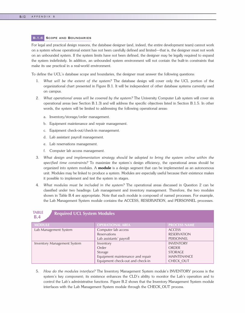
4. What modules must be included in the system? The operational areas discussed in Question 2 can beclassified under two headings: Lab management and inventory management. Therefore, the two modulesshown in Table B.4 are appropriate. Note that each module is composed of named processes. For example,the Lab Management System module contains the ACCESS, RESERVATION, and PERSONNEL processes.
TABLEB.4
Required UCL System Modules
MODULE OPERATIONAL AREA PROCESS NAMELab Management System Computer lab access
ReservationsLab assistants’ payroll
ACCESSRESERVATIONPERSONNEL
Inventory Management System InventoryOrderStorageEquipment maintenance and repairEquipment check-out and check-in
INVENTORYORDERSTORAGEMAINTENANCECHECK_OUT
5. How do the modules interface? The Inventory Management System module’s INVENTORY process is thesystem’s key component; its existence enhances the CLD’s ability to monitor the Lab’s operation and tocontrol the Lab’s administrative functions. Figure B.2 shows that the Inventory Management System moduleinterfaces with the Lab Management System module through the CHECK_OUT process.
45222_AppB 10/2/2009 8:32:41 Page 12
B-12 A P P E N D I X B
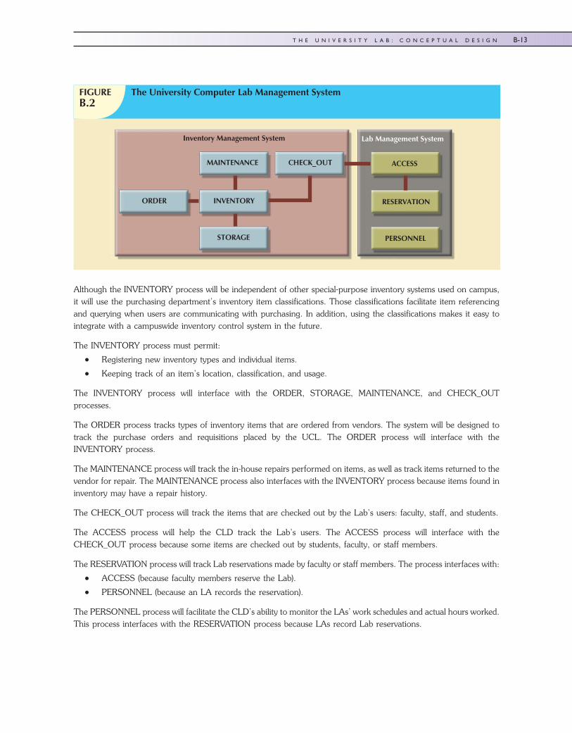
Although the INVENTORY process will be independent of other special-purpose inventory systems used on campus,it will use the purchasing department’s inventory item classifications. Those classifications facilitate item referencingand querying when users are communicating with purchasing. In addition, using the classifications makes it easy tointegrate with a campuswide inventory control system in the future.
The INVENTORY process must permit:
� Registering new inventory types and individual items.
� Keeping track of an item’s location, classification, and usage.
The INVENTORY process will interface with the ORDER, STORAGE, MAINTENANCE, and CHECK_OUTprocesses.
The ORDER process tracks types of inventory items that are ordered from vendors. The system will be designed totrack the purchase orders and requisitions placed by the UCL. The ORDER process will interface with theINVENTORY process.
The MAINTENANCE process will track the in-house repairs performed on items, as well as track items returned to thevendor for repair. The MAINTENANCE process also interfaces with the INVENTORY process because items found ininventory may have a repair history.
The CHECK_OUT process will track the items that are checked out by the Lab’s users: faculty, staff, and students.
The ACCESS process will help the CLD track the Lab’s users. The ACCESS process will interface with theCHECK_OUT process because some items are checked out by students, faculty, or staff members.
The RESERVATION process will track Lab reservations made by faculty or staff members. The process interfaces with:
� ACCESS (because faculty members reserve the Lab).
� PERSONNEL (because an LA records the reservation).
The PERSONNEL process will facilitate the CLD’s ability to monitor the LAs’ work schedules and actual hours worked.This process interfaces with the RESERVATION process because LAs record Lab reservations.
FIGUREB.2
The University Computer Lab Management System
MAINTENANCE CHECK_OUT
INVENTORYORDER
STORAGE
ACCESS
RESERVATION
PERSONNEL
Inventory Management System Lab Management System
45222_AppB 9/25/2009 12:40:52 Page 13
B-13T H E U N I V E R S I T Y L A B : C O N C E P T U A L D E S I G N
B.2 DATABASE DESIGN PHASE: CONCEPTUAL DESIGN
To develop a good conceptual design, you must be able to gather information that lets you accurately identify theentities and describe their attributes and relationships. The entity relationships must accurately reflect real-worldrelationships.
B.2.1 Information Sources and Users
The initial study phase generated much useful information from the system’s key users. The conceptual design phasemust be begun by confirming good information sources. The confirmation process recertifies key users and carefullycatalogs all current and prospective end users. In addition, the confirmation process targets the current system’s paperflow and documentation, including data and report forms. No document in the paper trail is considered irrelevant atthis stage. If the paper exists, somebody must have thought it was important at some point. For the UCL, the followinghave been confirmed:
� Assistant dean.
� Computer lab director (CLD).
� Computer lab secretary (CLS).
� Computer lab assistants (LA) and graduate assistants (GA).
� Students, faculty, and staff who use the Lab’s resources.
� All currently used computer lab forms, file folders, and report forms.
It is not surprising that a list of prospective system users tends to be a duplicate of at least a portion of the list ofinformation sources:
� The CLD (who is also the UCL system administrator) will manage the system, enter data into the database, anddefine reporting requirements.
� The LA and the GA are the primary UCL system users and will enter data into the database.
� The CLS is a system user and will query and update the database.
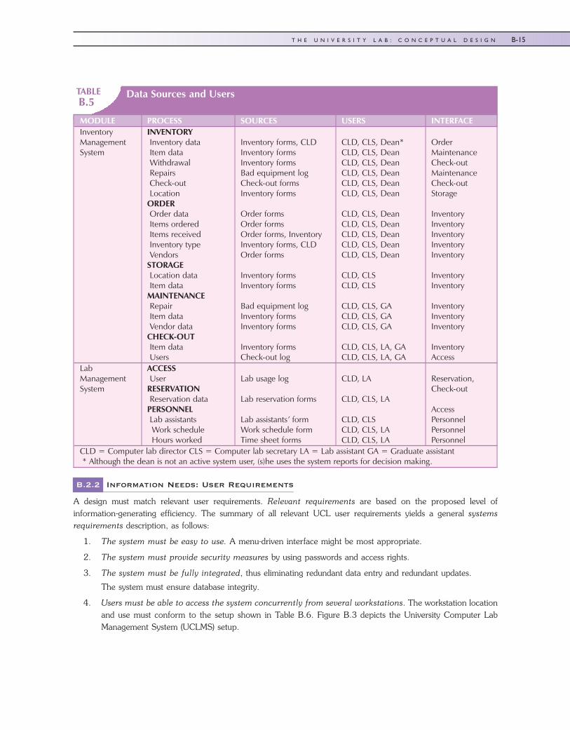
You should create a summary table to identify all system sources and users. You can use that table for cross-checking,thereby enabling you to audit sources and users more easily. The UCL system summary is shown in Table B.5. Notethat the summary table also identifies the proposed system modules, processes, and interfaces discussed in the previoussection.
45222_AppB 9/25/2009 12:40:52 Page 14
B-14 A P P E N D I X B
TABLEB.5
Data Sources and Users
MODULE PROCESS SOURCES USERS INTERFACEInventoryManagementSystem
INVENTORYInventory dataItem dataWithdrawalRepairsCheck-outLocation
ORDEROrder dataItems orderedItems receivedInventory typeVendors
STORAGELocation dataItem data
MAINTENANCERepairItem dataVendor data
CHECK-OUTItem dataUsers
Inventory forms, CLDInventory formsInventory formsBad equipment logCheck-out formsInventory forms
Order formsOrder formsOrder forms, InventoryInventory forms, CLDOrder forms
Inventory formsInventory forms
Bad equipment logInventory formsInventory forms
Inventory formsCheck-out log
CLD, CLS, Dean*CLD, CLS, DeanCLD, CLS, DeanCLD, CLS, DeanCLD, CLS, DeanCLD, CLS, Dean
CLD, CLS, DeanCLD, CLS, DeanCLD, CLS, DeanCLD, CLS, DeanCLD, CLS, Dean
CLD, CLSCLD, CLS
CLD, CLS, GACLD, CLS, GACLD, CLS, GA
CLD, CLS, LA, GACLD, CLS, LA, GA
OrderMaintenanceCheck-outMaintenanceCheck-outStorage
InventoryInventoryInventoryInventoryInventory
InventoryInventory
InventoryInventoryInventory
InventoryAccess
LabManagementSystem
ACCESSUser
RESERVATIONReservation data
PERSONNELLab assistantsWork scheduleHours worked
Lab usage log
Lab reservation forms
Lab assistants’ formWork schedule formTime sheet forms
CLD, LA
CLD, CLS, LA
CLD, CLSCLD, CLS, LACLD, CLS, LA
Reservation,Check-out
AccessPersonnelPersonnelPersonnel
CLD = Computer lab director CLS = Computer lab secretary LA = Lab assistant GA = Graduate assistant* Although the dean is not an active system user, (s)he uses the system reports for decision making.
B.2.2 Information Needs: User Requirements
A design must match relevant user requirements. Relevant requirements are based on the proposed level ofinformation-generating efficiency. The summary of all relevant UCL user requirements yields a general systemsrequirements description, as follows:
1. The system must be easy to use. A menu-driven interface might be most appropriate.
2. The system must provide security measures by using passwords and access rights.
3. The system must be fully integrated, thus eliminating redundant data entry and redundant updates.
The system must ensure database integrity.
4. Users must be able to access the system concurrently from several workstations. The workstation locationand use must conform to the setup shown in Table B.6. Figure B.3 depicts the University Computer LabManagement System (UCLMS) setup.
45222_AppB 9/25/2009 12:40:52 Page 15
B-15T H E U N I V E R S I T Y L A B : C O N C E P T U A L D E S I G N
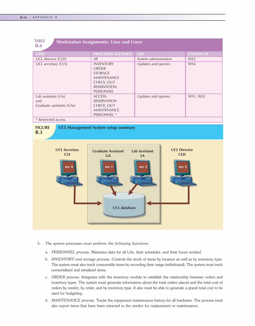
TABLEB.6
Workstation Assignments: Uses and Users
USER PROCESSES ACCESSED USE STATION IDUCL director (CLD) All System administration WS3UCL secretary (CLS) INVENTORY
ORDERSTORAGEMAINTENANCECHECK_OUTRESERVATIONPERSONNEL
Updates and queries WS4
Lab assistants (LAs)andGraduate assistants (GAs)
ACCESSRESERVATIONCHECK_OUTMAINTENANCEPERSONNEL *
Updates and queries WS1, WS2
* Restricted access.
5. The system processes must perform the following functions:
a. PERSONNEL process. Maintains data for all LAs, their schedules, and their hours worked.
b. INVENTORY and storage process. Controls the stock of items by location as well as by inventory type.The system must also track consumable items by recording their usage (withdrawal). The system must tracknonserialized and serialized items.
c. ORDER process. Integrates with the inventory module to establish the relationship between orders andinventory types. The system must generate information about the total orders placed and the total cost oforders by vendor, by order, and by inventory type. It also must be able to generate a grand total cost to beused for budgeting.
d. MAINTENANCE process. Tracks the equipment maintenance history for all hardware. The process mustalso report items that have been returned to the vendor for replacement or maintenance.
ws 4 ws 1 ws 2 ws 3
Graduate AssistantGA
Lab AssistantLA
UCL DirectorCLD
UCL SecretaryCLS
FIGUREB.3
UCL Management System setup summary
UCL database
45222_AppB 9/25/2009 12:40:52 Page 16
B-16 A P P E N D I X B
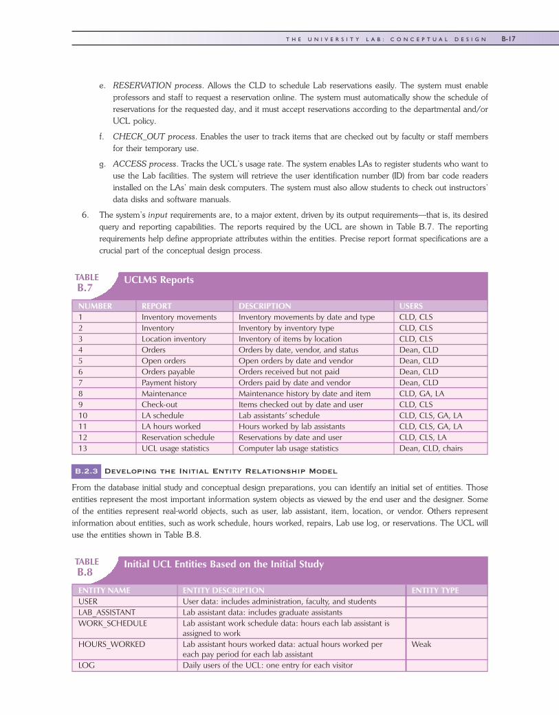
e. RESERVATION process. Allows the CLD to schedule Lab reservations easily. The system must enableprofessors and staff to request a reservation online. The system must automatically show the schedule ofreservations for the requested day, and it must accept reservations according to the departmental and/orUCL policy.
f. CHECK_OUT process. Enables the user to track items that are checked out by faculty or staff membersfor their temporary use.
g. ACCESS process. Tracks the UCL’s usage rate. The system enables LAs to register students who want touse the Lab facilities. The system will retrieve the user identification number (ID) from bar code readersinstalled on the LAs’ main desk computers. The system must also allow students to check out instructors’data disks and software manuals.
6. The system’s input requirements are, to a major extent, driven by its output requirements—that is, its desiredquery and reporting capabilities. The reports required by the UCL are shown in Table B.7. The reportingrequirements help define appropriate attributes within the entities. Precise report format specifications are acrucial part of the conceptual design process.
TABLEB.7
UCLMS Reports
NUMBER REPORT DESCRIPTION USERS1 Inventory movements Inventory movements by date and type CLD, CLS2 Inventory Inventory by inventory type CLD, CLS3 Location inventory Inventory of items by location CLD, CLS4 Orders Orders by date, vendor, and status Dean, CLD5 Open orders Open orders by date and vendor Dean, CLD6 Orders payable Orders received but not paid Dean, CLD7 Payment history Orders paid by date and vendor Dean, CLD8 Maintenance Maintenance history by date and item CLD, GA, LA9 Check-out Items checked out by date and user CLD, CLS10 LA schedule Lab assistants’ schedule CLD, CLS, GA, LA11 LA hours worked Hours worked by lab assistants CLD, CLS, GA, LA12 Reservation schedule Reservations by date and user CLD, CLS, LA13 UCL usage statistics Computer lab usage statistics Dean, CLD, chairs
B.2.3 Developing the Initial Entity Relationship Model
From the database initial study and conceptual design preparations, you can identify an initial set of entities. Thoseentities represent the most important information system objects as viewed by the end user and the designer. Someof the entities represent real-world objects, such as user, lab assistant, item, location, or vendor. Others representinformation about entities, such as work schedule, hours worked, repairs, Lab use log, or reservations. The UCL willuse the entities shown in Table B.8.
TABLEB.8
Initial UCL Entities Based on the Initial Study
ENTITY NAME ENTITY DESCRIPTION ENTITY TYPEUSER User data: includes administration, faculty, and studentsLAB_ASSISTANT Lab assistant data: includes graduate assistantsWORK_SCHEDULE Lab assistant work schedule data: hours each lab assistant is
assigned to workHOURS_WORKED Lab assistant hours worked data: actual hours worked per
each pay period for each lab assistantWeak
LOG Daily users of the UCL: one entry for each visitor
45222_AppB 9/25/2009 12:40:52 Page 17
B-17T H E U N I V E R S I T Y L A B : C O N C E P T U A L D E S I G N
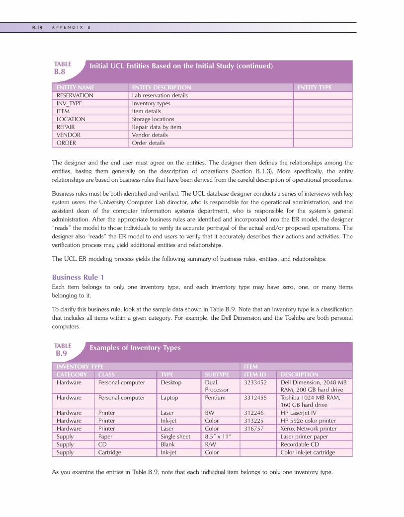
TABLEB.8
Initial UCL Entities Based on the Initial Study (continued)
ENTITY NAME ENTITY DESCRIPTION ENTITY TYPERESERVATION Lab reservation detailsINV_TYPE Inventory typesITEM Item detailsLOCATION Storage locationsREPAIR Repair data by itemVENDOR Vendor detailsORDER Order details
The designer and the end user must agree on the entities. The designer then defines the relationships among theentities, basing them generally on the description of operations (Section B.1.3). More specifically, the entityrelationships are based on business rules that have been derived from the careful description of operational procedures.
Business rules must be both identified and verified. The UCL database designer conducts a series of interviews with keysystem users: the University Computer Lab director, who is responsible for the operational administration, and theassistant dean of the computer information systems department, who is responsible for the system’s generaladministration. After the appropriate business rules are identified and incorporated into the ER model, the designer“reads” the model to those individuals to verify its accurate portrayal of the actual and/or proposed operations. Thedesigner also “reads” the ER model to end users to verify that it accurately describes their actions and activities. Theverification process may yield additional entities and relationships.
The UCL ER modeling process yields the following summary of business rules, entities, and relationships:
Business Rule 1Each item belongs to only one inventory type, and each inventory type may have zero, one, or many itemsbelonging to it.
To clarify this business rule, look at the sample data shown in Table B.9. Note that an inventory type is a classificationthat includes all items within a given category. For example, the Dell Dimension and the Toshiba are both personalcomputers.
TABLEB.9
Examples of Inventory Types
INVENTORY TYPE ITEMCATEGORY CLASS TYPE SUBTYPE ITEM ID DESCRIPTIONHardware Personal computer Desktop Dual
Processor3233452 Dell Dimension, 2048 MB
RAM, 200 GB hard driveHardware Personal computer Laptop Pentium 3312455 Toshiba 1024 MB RAM,
160 GB hard driveHardware Printer Laser BW 312246 HP LaserJet IVHardware Printer Ink-jet Color 313225 HP 592e color printerHardware Printer Laser Color 316757 Xerox Network printerSupply Paper Single sheet 8.5” x 11” Laser printer paperSupply CD Blank R/W Recordable CDSupply Cartridge Ink-jet Color Color ink-jet cartridge
As you examine the entries in Table B.9, note that each individual item belongs to only one inventory type.
45222_AppB 9/25/2009 12:40:52 Page 18
B-18 A P P E N D I X B
The first business rule leads to the ER model segment shown in Figure B.4.
Business Rule 2An item may be put in use upon its arrival, or it may be stored. In other words, an item might not be stored at all. Someitems, such as printer cartridges, are part of a generic grouping and may be stored in more than one location.Therefore, some items could be stored in zero, one, or more locations. Each storage location might store zero, one,or many items. (See Figure B.5.)
Business Rule 3An order references only one vendor, and each vendor may have zero, one, or many orders. (See Figure B.6.)
FIGUREB.4
The ER model segment for business rule 1
FIGUREB.5
The ER model segment for business rule 2
FIGUREB.6
The ER model segment for business rule 3
45222_AppB 9/25/2009 12:40:53 Page 19
B-19T H E U N I V E R S I T Y L A B : C O N C E P T U A L D E S I G N
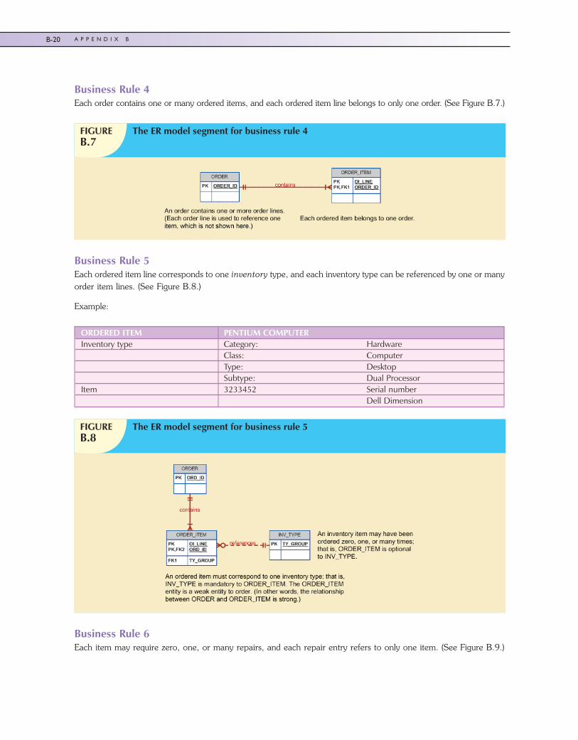
Business Rule 4Each order contains one or many ordered items, and each ordered item line belongs to only one order. (See Figure B.7.)
Business Rule 5Each ordered item line corresponds to one inventory type, and each inventory type can be referenced by one or manyorder item lines. (See Figure B.8.)
Example:
Business Rule 6Each item may require zero, one, or many repairs, and each repair entry refers to only one item. (See Figure B.9.)
FIGUREB.7
The ER model segment for business rule 4
ORDERED ITEM PENTIUM COMPUTERInventory type Category: Hardware
Class: ComputerType: DesktopSubtype: Dual Processor
Item 3233452 Serial numberDell Dimension
FIGUREB.8
The ER model segment for business rule 5
45222_AppB 9/25/2009 12:40:53 Page 20
B-20 A P P E N D I X B
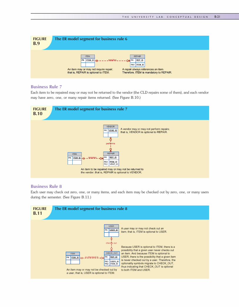
Business Rule 7Each item to be repaired may or may not be returned to the vendor (the CLD repairs some of them), and each vendormay have zero, one, or many repair items returned. (See Figure B.10.)
Business Rule 8Each user may check out zero, one, or many items, and each item may be checked out by zero, one, or many usersduring the semester. (See Figure B.11.)
FIGUREB.9
The ER model segment for business rule 6
FIGUREB.10
The ER model segment for business rule 7
FIGUREB.11
The ER model segment for business rule 8
45222_AppB 9/25/2009 12:40:53 Page 21
B-21T H E U N I V E R S I T Y L A B : C O N C E P T U A L D E S I G N
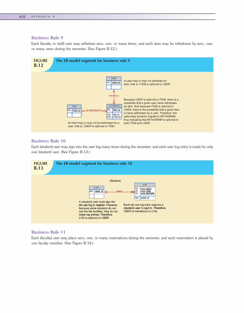
Business Rule 9Each (faculty or staff) user may withdraw zero, one, or many items, and each item may be withdrawn by zero, one,or many users during the semester. (See Figure B.12.)
Business Rule 10Each (student) user may sign into the user log many times during the semester, and each user log entry is made by onlyone (student) user. (See Figure B.13.)
Business Rule 11Each (faculty) user may place zero, one, or many reservations during the semester, and each reservation is placed byone faculty member. (See Figure B.14.)
FIGUREB.12
The ER model segment for business rule 9
FIGUREB.13
The ER model segment for business rule 10
45222_AppB 9/25/2009 12:40:54 Page 22
B-22 A P P E N D I X B
Business Rule 12Each reservation is recorded by an LA, and each LA may record zero, one, or many reservations during the semester.(See Figure B.15.)
Business Rule 13Each LA is assigned to work at least one day in each week’s work schedule, and each work schedule assignment ismade for one LA. (See Figure B.16.)
Business Rule 14Each LA accumulates hours worked during each two-week pay period, and each “hours worked” entry is associatedwith one LA. (See Figure B.17.)
FIGUREB.14
The ER model segment for business rule 11
FIGUREB.15
The ER model segment for business rule 12
FIGUREB.16
The ER model segment for business rule 13
45222_AppB 9/25/2009 12:40:54 Page 23
B-23T H E U N I V E R S I T Y L A B : C O N C E P T U A L D E S I G N
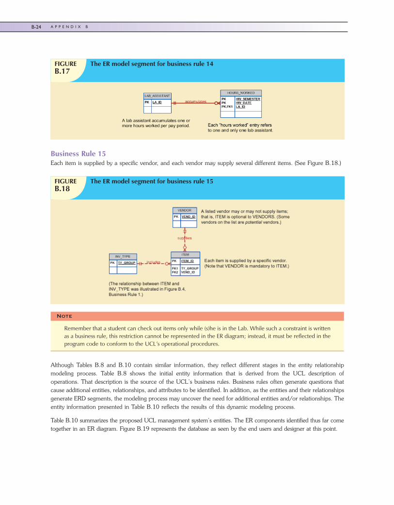
Business Rule 15Each item is supplied by a specific vendor, and each vendor may supply several different items. (See Figure B.18.)
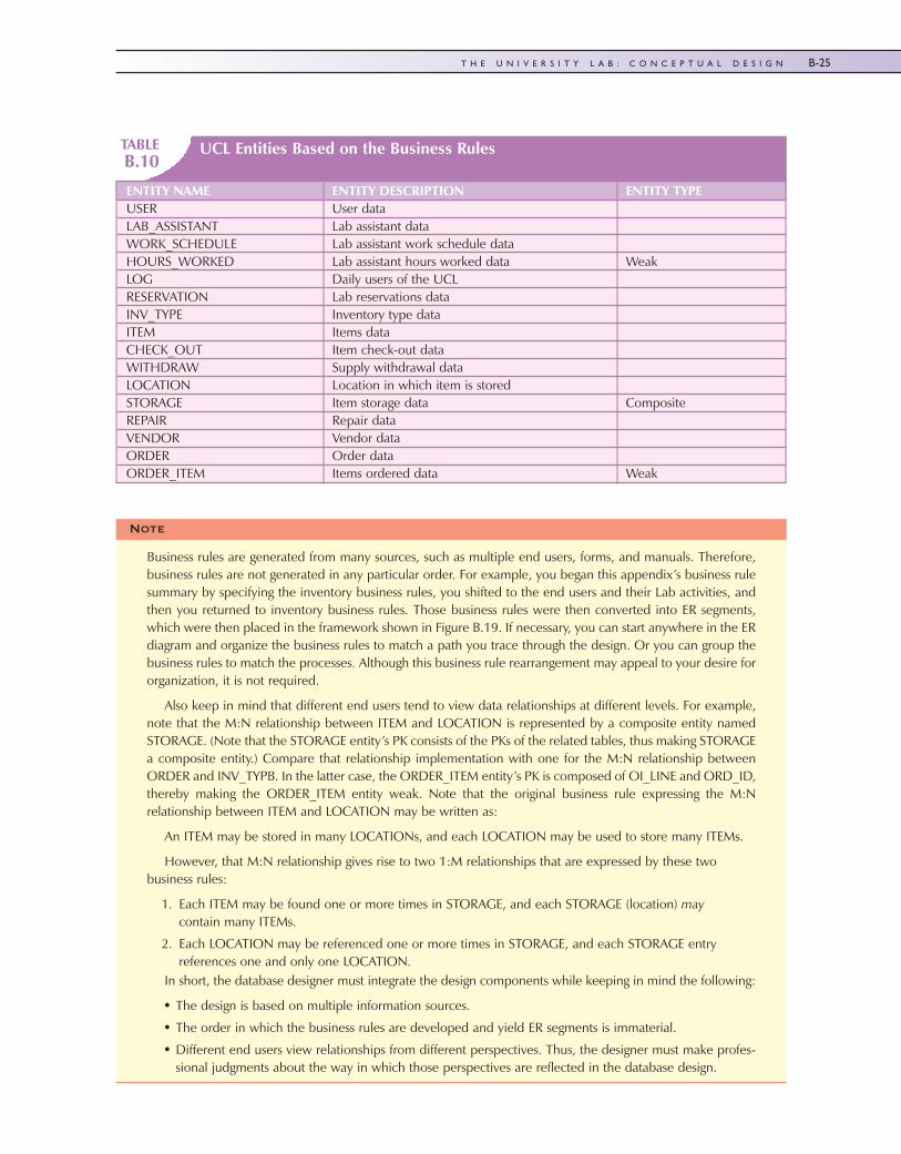
Although Tables B.8 and B.10 contain similar information, they reflect different stages in the entity relationshipmodeling process. Table B.8 shows the initial entity information that is derived from the UCL description ofoperations. That description is the source of the UCL’s business rules. Business rules often generate questions thatcause additional entities, relationships, and attributes to be identified. In addition, as the entities and their relationshipsgenerate ERD segments, the modeling process may uncover the need for additional entities and/or relationships. Theentity information presented in Table B.10 reflects the results of this dynamic modeling process.
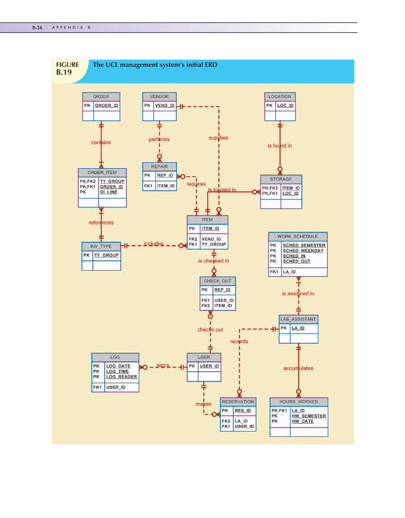
Table B.10 summarizes the proposed UCL management system’s entities. The ER components identified thus far cometogether in an ER diagram. Figure B.19 represents the database as seen by the end users and designer at this point.
FIGUREB.17
The ER model segment for business rule 14
FIGUREB.18
The ER model segment for business rule 15
Note
Remember that a student can check out items only while (s)he is in the Lab. While such a constraint is writtenas a business rule, this restriction cannot be represented in the ER diagram; instead, it must be reflected in theprogram code to conform to the UCL’s operational procedures.
45222_AppB 9/25/2009 12:40:54 Page 24
B-24 A P P E N D I X B
TABLEB.10
UCL Entities Based on the Business Rules
ENTITY NAME ENTITY DESCRIPTION ENTITY TYPEUSER User dataLAB_ASSISTANT Lab assistant dataWORK_SCHEDULE Lab assistant work schedule dataHOURS_WORKED Lab assistant hours worked data WeakLOG Daily users of the UCLRESERVATION Lab reservations dataINV_TYPE Inventory type dataITEM Items dataCHECK_OUT Item check-out dataWITHDRAW Supply withdrawal dataLOCATION Location in which item is storedSTORAGE Item storage data CompositeREPAIR Repair dataVENDOR Vendor dataORDER Order dataORDER_ITEM Items ordered data Weak
Note
Business rules are generated from many sources, such as multiple end users, forms, and manuals. Therefore,business rules are not generated in any particular order. For example, you began this appendix’s business rulesummary by specifying the inventory business rules, you shifted to the end users and their Lab activities, andthen you returned to inventory business rules. Those business rules were then converted into ER segments,which were then placed in the framework shown in Figure B.19. If necessary, you can start anywhere in the ERdiagram and organize the business rules to match a path you trace through the design. Or you can group thebusiness rules to match the processes. Although this business rule rearrangement may appeal to your desire fororganization, it is not required.
Also keep in mind that different end users tend to view data relationships at different levels. For example,note that the M:N relationship between ITEM and LOCATION is represented by a composite entity namedSTORAGE. (Note that the STORAGE entity’s PK consists of the PKs of the related tables, thus making STORAGEa composite entity.) Compare that relationship implementation with one for the M:N relationship betweenORDER and INV_TYPB. In the latter case, the ORDER_ITEM entity’s PK is composed of OI_LINE and ORD_ID,thereby making the ORDER_ITEM entity weak. Note that the original business rule expressing the M:Nrelationship between ITEM and LOCATION may be written as:
An ITEM may be stored in many LOCATIONs, and each LOCATION may be used to store many ITEMs.
However, that M:N relationship gives rise to two 1:M relationships that are expressed by these twobusiness rules:
1. Each ITEM may be found one or more times in STORAGE, and each STORAGE (location) maycontain many ITEMs.
2. Each LOCATION may be referenced one or more times in STORAGE, and each STORAGE entryreferences one and only one LOCATION.
In short, the database designer must integrate the design components while keeping in mind the following:
• The design is based on multiple information sources.
• The order in which the business rules are developed and yield ER segments is immaterial.
• Different end users view relationships from different perspectives. Thus, the designer must make profes-sional judgments about the way in which those perspectives are reflected in the database design.
45222_AppB 9/25/2009 12:40:55 Page 25
B-25T H E U N I V E R S I T Y L A B : C O N C E P T U A L D E S I G N
FIGUREB.19
The UCL management system’s initial ERD
45222_AppB 9/25/2009 12:40:55 Page 26
B-26 A P P E N D I X B
K e y T e r m s
module, B-12 nonserialized items, B-5 serialized items, B-5
R e v i e w Q u e s t i o n s
1. What factors relevant to database design are revealed during the initial study phase?
2. Why is the organizational structure relevant to the database designer?
3. What is the difference between the database design scope and its boundaries? Why is the scope and boundarystatement so important to the database designer?
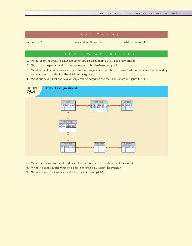
4. What business rule(s) and relationships can be described for the ERD shown in Figure QB.4?
5. Write the connectivity and cardinality for each of the entities shown in Question 4.
6. What is a module, and what role does a module play within the system?
7. What is a module interface, and what does it accomplish?
FIGUREQB.4
The ERD for Question 4
45222_AppB 10/2/2009 8:37:52 Page 27
B-27T H E U N I V E R S I T Y L A B : C O N C E P T U A L D E S I G N
P r o b l e m s
1. Modify the initial ER diagram presented in Figure B.19 to include the following entity supertype and subtypes:The University Computer Lab USER may be a student or a faculty member.
2. Using an ER diagram, illustrate how the change you made in Problem 1 affects the relationship of the USERentity to the following entities:
a. LOG
b. RESERVATION
c. CHECK_OUT
d. WITHDRAW
3. Create the initial ER diagram for a car dealership. The dealership sells both new and used cars, and it operatesa service facility. Base your design on the following business rules:
a. A salesperson can sell many cars, but each car is sold by only one salesperson.
b. A customer can buy many cars, but each car is sold to only one customer.
c. A salesperson writes a single invoice for each car sold.
d. A customer gets an invoice for each car (s)he buys.
e. A customer might come in only to have a car serviced; that is, one need not buy a car to be classified as acustomer.
f. When a customer takes in one or more cars for repair or service, one service ticket is written for each car.
g. The car dealership maintains a service history for each car serviced. The service records are referenced bythe car’s serial number.
h. A car brought in for service can be worked on by many mechanics, and each mechanic can work on many cars.
i. A car that is serviced may or may not need parts. (For example, parts are not necessary to adjust a carburetoror to clean a fuel injector nozzle.)
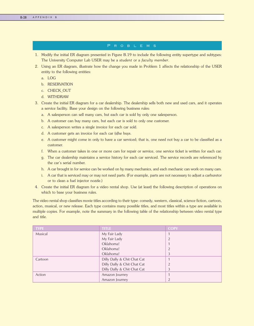
4. Create the initial ER diagram for a video rental shop. Use (at least) the following description of operations onwhich to base your business rules.
The video rental shop classifies movie titles according to their type: comedy, western, classical, science fiction, cartoon,action, musical, or new release. Each type contains many possible titles, and most titles within a type are available inmultiple copies. For example, note the summary in the following table of the relationship between video rental typeand title.
TYPE TITLE COPYMusical My Fair Lady
My Fair LadyOklahoma!Oklahoma!Oklahoma!
12123
Cartoon Dilly Dally & Chit Chat CatDilly Dally & Chit Chat CatDilly Dally & Chit Chat Cat
123
Action Amazon JourneyAmazon Journey
12
45222_AppB 9/25/2009 12:40:56 Page 28
B-28 A P P E N D I X B
Keep the following conditions in mind as you design the video rental database:
� The movie type classification is standard; not all types are necessarily in stock.
� The movie list is updated as necessary; however, a movie on that list might not be ordered if the video shopowner decides that the movie is not desirable for some reason.
� The video rental shop does not necessarily order movies from all vendors on the vendor list; some vendors onthe vendor list are merely potential vendors from whom movies may be ordered in the future.
� Movies classified as new releases are reclassified to an appropriate type after they have been in stock for morethan 30 days. The video shop manager wants to have an end-of-period (week, month, year) report for thenumber of rentals by type.
� If a customer requests a title, the clerk must be able to find it quickly. When a customer selects one or moretitles, an invoice is written. Each invoice can contain charges for one or more titles. All customers pay in cash.
� When a customer checks out a title, a record is kept of the check-out date and time and the expected returndate and time. When rented titles are returned, the clerk must be able to check quickly whether the return islate and to assess the appropriate late return fee.
� The video store owner wants to generate periodic revenue reports by title and by type. The owner also wantsto generate periodic inventory reports and track titles on order.
� The video store owner, who employs two (salaried) full-time and three (hourly) part-time employees, wants tokeep track of all employee work time and payroll data. Part-time employees must arrange entries in a workschedule, while all employees sign in and out on a work log.
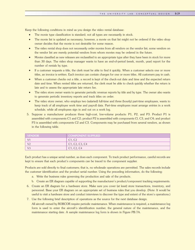
5. Suppose a manufacturer produces three high-cost, low-volume products: P1, P2, and P3. Product P1 isassembled with components C1 and C2; product P2 is assembled with components Cl, C3, and C4; and productP3 is assembled with components C2 and C3. Components may be purchased from several vendors, as shownin the following table.
Each product has a unique serial number, as does each component. To track product performance, careful records arekept to ensure that each product’s components can be traced to the component supplier.
Products are sold directly to final customers; that is, no wholesale operations are permitted. The sales records includethe customer identification and the product serial number. Using the preceding information, do the following:
a. Write the business rules governing the production and sale of the products.
b. Create an ER diagram capable of supporting the manufacturer’s product/component tracking requirements.
6. Create an ER diagram for a hardware store. Make sure you cover (at least) store transactions, inventory, andpersonnel. Base your ER diagram on an appropriate set of business rules that you develop. (Note: It would beuseful to visit a hardware store and conduct interviews to discover the type and extent of the store’s operations.)
7. Use the following brief description of operations as the source for the next database design.
All aircraft owned by ROBCOR require periodic maintenance. When maintenance is required, a maintenance logform is used to enter the aircraft’s identification number, the general nature of the maintenance, and themaintenance starting date. A sample maintenance log form is shown in Figure PB.7A.
VENDOR COMPONENT SUPPLIEDV1 C1, C2V2 C1, C2, C3, C4V3 C1, C2, C4
45222_AppB 9/25/2009 12:40:56 Page 29
B-29T H E U N I V E R S I T Y L A B : C O N C E P T U A L D E S I G N
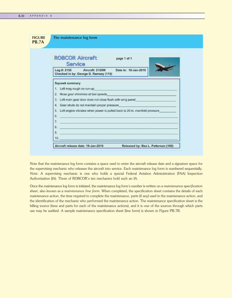
Note that the maintenance log form contains a space used to enter the aircraft release date and a signature space forthe supervising mechanic who releases the aircraft into service. Each maintenance log form is numbered sequentially.Note: A supervising mechanic is one who holds a special Federal Aviation Administration (FAA) InspectionAuthorization (IA). Three of ROBCOR’s ten mechanics hold such an IA.
Once the maintenance log form is initiated, the maintenance log form’s number is written on a maintenance specificationsheet, also known as a maintenance line form. When completed, the specification sheet contains the details of eachmaintenance action, the time required to complete the maintenance, parts (if any) used in the maintenance action, andthe identification of the mechanic who performed the maintenance action. The maintenance specification sheet is thebilling source (time and parts for each of the maintenance actions), and it is one of the sources through which partsuse may be audited. A sample maintenance specification sheet (line form) is shown in Figure PB.7B.
FIGUREPB.7A
The maintenance log form
45222_AppB 10/2/2009 9:21:9 Page 30
B-30 A P P E N D I X B
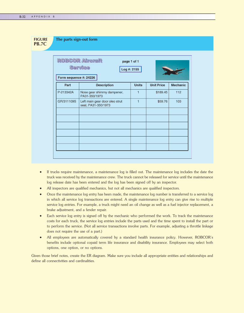
Parts used in any maintenance action must be signed out by the mechanic who used them, thus allowing ROBCORto track its parts inventory. Each sign-out form contains a listing of all parts associated with a given maintenance logentry. Therefore, a parts sign-out form contains the maintenance log number against which the parts are charged. Inaddition, the parts sign-out procedure is used to update the ROBCOR parts inventory. A sample parts sign-out formis shown in Figure PB.7C.
Mechanics are highly specialized ROBCOR employees, and their qualifications are quite different from those of anaccountant or a secretary, for example.
Given this brief description of operations and using the Chen ER methodology, draw the fully labeled ER diagram.Make sure you include all appropriate relationships, connectivities, and cardinalities.
8. You have just been employed by the ROBCOR Trucking Company to develop a database. To gain a sense of thedatabase’s intended functions, you spent some time talking to ROBCOR’s employees and you examined someof the forms used to track driver assignments and truck maintenance. Your notes include the followingobservations:
� Some drivers are qualified to drive more than one type of truck operated by ROBCOR. A driver may, therefore,be assigned to drive more than one truck type during some period of time. ROBCOR operates several trucksof a given type. For example, ROBCOR operates two panel trucks, four half-ton pick-up trucks, two single-axledump trucks, one double-axle truck, and one 16-wheel truck. A driver with a chauffeur’s license is qualified todrive only a panel truck and a half-ton pick-up truck and, thus, may be assigned to drive any one of six trucks.A driver with a commercial license with an appropriate heavy equipment endorsement may be assigned to driveany of the nine trucks in the ROBCOR fleet. Each time a driver is assigned to drive a truck, an entry is madein a log containing the employee number, the truck identification, and the sign-out (departure) date. Upon thedriver’s return, the log is updated to include the sign-in (return) date and the number of driver duty hours.
FIGUREPB.7B
The maintenance line form
45222_AppB 9/25/2009 12:46:3 Page 31
B-31T H E U N I V E R S I T Y L A B : C O N C E P T U A L D E S I G N
� If trucks require maintenance, a maintenance log is filled out. The maintenance log includes the date thetruck was received by the maintenance crew. The truck cannot be released for service until the maintenancelog release date has been entered and the log has been signed off by an inspector.
� All inspectors are qualified mechanics, but not all mechanics are qualified inspectors.
� Once the maintenance log entry has been made, the maintenance log number is transferred to a service login which all service log transactions are entered. A single maintenance log entry can give rise to multipleservice log entries. For example, a truck might need an oil change as well as a fuel injector replacement, abrake adjustment, and a fender repair.
� Each service log entry is signed off by the mechanic who performed the work. To track the maintenancecosts for each truck, the service log entries include the parts used and the time spent to install the part orto perform the service. (Not all service transactions involve parts. For example, adjusting a throttle linkagedoes not require the use of a part.)
� All employees are automatically covered by a standard health insurance policy. However, ROBCOR’sbenefits include optional copaid term life insurance and disability insurance. Employees may select bothoptions, one option, or no options.
Given those brief notes, create the ER diagram. Make sure you include all appropriate entities and relationships anddefine all connectivities and cardinalities.
FIGUREPB.7C
The parts sign-out form
45222_AppB 9/25/2009 12:46:11 Page 32
B-32 A P P E N D I X B


![Ch.5 Conceptual Design Process. - IEMS. Conceptual Design Process.pdf · - 4 - ■ Conceptual Design. [Blanchard, pp123 - 150] Conceptual Design Process. ․ Needs Analysis and Identification](https://img.pdfslide.us/doc/110x75/5a7a012d7f8b9a3d058c8530/ch5-conceptual-design-process-conceptual-design-processpdf-4-conceptual.jpg)