Embed Size (px)
DESCRIPTION
it is a seminar report on USB 3.0
Citation preview

THE UNIVERSAL SERIAL BUS 3.0SEMINAR REPORT
Submitted by
ARJUN C C
in partial fulfillment for the award of the degree
of
BACHELOR OF TECHNOLOGY
in
COMPUTER SCIENCE AND ENGINEERING
SREE NARAYANA GURUKULAM COLLEGE OF ENGINEERING
KADAYIRUPPU, KOLENCHERY 682311
MAHATMA GANDHI UNIVERSITY: KOTTAYAM 686580
OCTOBER 2009

SREE NARAYANA GURUKULAM COLLEGE OF ENGINEERING,
KOLENCHERYDEPARTMENT OF COMPUTER SCIENCE AND ENGINEERING
CERTIFICATE
Certified that the seminar report “THE UNIVERSAL SERIAL BUS 3.0” is
the bonafide work done by “ARJUN C C” in partial fulfillment of award of
B.Tech Degree in “COMPUTER SCIENCE AND ENGINEERING”.
Mr. Prof. K. Girija Sankar Mrs.Silpa Kamalan ,Lecturer,CSE
HEAD OF THE DEPARTMENT GUIDE
Submitted for the Viva-Voce examination on …………………………………….
Name and Signature of Name and signature of Internal Examiner External Examiner

ACKNOWLEDGEMENT
Dedicating this seminar to the Almighty God whose abundant grace and mercies enabled its
successful completion, I would like to express my profound gratitude to all the people who had inspired and
motivated me to undertake this seminar.
I wish to express our sincere thanks to our Head of the Department, Mr. Prof. K. Girija Sankar, for
providing an opportunity to undertake this seminar. I am deeply indebted to my seminar guide Mrs.Silpa
Kamalan, lecturer in the Department of Computer Science and Engineering for providing me with valuable
advice and guidance during the course of the seminar.
Finally I would like to express my gratitude to Sree Narayana Gurukulam College of Engineering for
providing me with all the required facilities without which the seminar would not have been possible.

TABLE OF CONTENTS
TITLE PAGE NO
ABSTRACT
ACKNOWLEDGEMENTS
CHAPTER 1: INTRODUCTION 6
CHAPTER 2: HISTORY 7
CHAPTER 3: ARCHITECTURE 9
CHAPTER 4: PHYSICAL STRUCTURE 12
CHAPTER 5: FEATURES 16
CHAPTER 6: COMPARISON 19
CHAPTER 7: APPLICATION 22
CHAPTER 8: CONCLUSION 24
CHAPTER 9: REFERENCE 25

UNIVERSAL SERIAL BUS 3.0
ABSTRACT
In information technology, Universal Serial Bus (USB) is a serial bus standard to connect devices to
a host computer. USB was designed to allow many peripherals to be connected using a single standardized
interface socket and to improve plug and play capabilities by allowing hot swapping; that is, by allowing
devices to be connected and disconnected without rebooting the computer or turning off the device. Other
convenient features include providing power to low-consumption devices, eliminating the need for an
external power supply; and allowing many devices to be used without requiring manufacturer-specific device
drivers to be installed.
The U S B 3.0 is the upcoming version of the Universal Serial Bus (USB). The specification of the
new standard had been announced by USB Implementers Forum (USB-IF). The main feature of the new USB
is the raw throughput is 500 MByte/s. The new USB is also capable to provide more power to drive the
devices. USB 3.0 is highly backward compatible that is, it is capable of operating with the current USBs
which is USB 2.0
S.N. G.C.E. Kadayiruppu 5

UNIVERSAL SERIAL BUS 3.0
CHAPTER 1
INTRODUCTION
Universal Serial Bus (USB) is a serial bus standard to connect devices to a host computer. The USB
3.0 is the upcoming version of the USB. The USB 3.0 is also called super speed USB. Because the USB 3.0
support a raw throughput of 500MByte/s. As its previous versions it also support the plug and play capability,
hot swapping etc. USB was designed to allow many peripherals to be connected using a single standardized
interface socket. . Other convenient features include providing power to low-consumption devices, eliminat
ing the need for an external power supply; and allowing many devices to be used without requiring manufac
turer-specific device drivers to be installed.
There are many new features included in the new Universal Serial Bus Specification. The most im
portant one is the supers speed data transfer itself. Then the USB 3.0 can support more devices than the cur
rently using specification which is USB 2.0. The bus power spec has been increased so that a unit load is
150mA (+50% over minimum using USB 2.0). An unconfigured device can still draw only 1 unit load, but a
configured device can draw up to 6 unit loads (900mA, an 80% increase over USB 2.0 at a registered maxim
um of 500mA). Minimum device operating voltage is dropped from 4.4V to 4V. When operating in Super
Speed mode, full-duplex signaling occurs over 2 differential pairs separate from the non-SuperSpeed differ
ential pair. This result in USB 3.0 cables containing 2 wires for power and ground, 2 wires for non-Super
Speed data, and 4 wires for SuperSpeed data, and a shield (not required in previous specifications).
S.N. G.C.E. Kadayiruppu 6

UNIVERSAL SERIAL BUS 3.0
CHAPTER 2
HISTORY
Prereleases
• USB 0.7: Released in November 1994.
• USB 0.8: Released in December 1994.
• USB 0.9: Released in April 1995.
• USB 0.99: Released in August 1995.
• USB 1.0: Release Candidate: Released in November 1995.
USB 1.0
• USB 1.0: Released in January 1996.
Specified data rates of 1.5 Mbit/s (Low-Speed) and 12 Mbit/s (Full-Speed). Does not allow for ex
tension cables or pass-through monitors (due to timing and power limitations). Few such devices actu
ally made it to market.
• USB 1.1: Released in September 1998.
Fixed problems identified in 1.0, mostly relating to hubs. Earliest revision to be widely adopted.
USB 2.0
USB 2.0: Released in April 2000.Added higher maximum speed of 480 Mbit/s (now called Hi-Speed). Further modifications to the USB specification have been done via Engineering Change Notices (ECN). The most important of these ECNs are included into the USB 2.0 specification package available from USB.org:
• Mini-B Connector ECN: Released in October 2000.Specifications for Mini-B plug and receptacle. These should not be confused with Micro-B plug and receptacle.
• Pull-up/Pull-down Resistors ECN: Released in May 2002.
S.N. G.C.E. Kadayiruppu 7

UNIVERSAL SERIAL BUS 3.0
• Interface Associations ECN: Released in May 2003.New standard descriptor was added that allows multiple interfaces to be associated with a single device function.
• Rounded Chamfer ECN: Released in October 2003.A recommended, compatible change to Mini-B plugs that results in longer lasting connectors.
• Inter-Chip USB Supplement: Released in March 2006.• On-The-Go Supplement 1.3: Released in December 2006.
USB On-The-Go makes it possible for two USB devices to communicate with each other without requiring a separate USB host. In practice, one of the USB devices acts as a host for the other device.
• Battery Charging Specification 1.0: Released in March 2007.Adds support for dedicated chargers (power supplies with USB connectors), host chargers (USB hosts that can act as chargers) and the No Dead Battery provision which allows devices to temporarily draw 100 mA current after they have been attached. If a USB device is connected to dedicated charger, maximum current drawn by the device may be as high as 1.8A. (Note that this document is not distributed with USB 2.0 specification package.)
• Micro-USB Cables and Connectors Specification 1.01: Released in April 2007.• Link Power Management Addendum ECN: Released in July 2007.
This adds a new power state between enabled and suspended states. Device in this state is not required to reduce its power consumption. However, switching between enabled and sleep states is much faster than switching between enabled and suspended states, which allows devices to sleep while idle.
• High-Speed Inter-Chip USB Electrical Specification Revision 1.0: Released in September 2007.
USB 3.0• On September 18, 2007, Pat Gelsinger demonstrated USB 3.0 at the Intel Developer Forum. The USB
3.0 Promoter Group announced on November 17, 2008, that version 1.0 of the specification has been
completed and is transitioned to the USB Implementers Forum (USB-IF), the managing body of USB
specifications. This move effectively opens the spec to hardware developers for implementation in
future products.
S.N. G.C.E. Kadayiruppu 8

UNIVERSAL SERIAL BUS 3.0
CHAPTER 3
ARCHITECTURE
ARCHITECTURAL COMPONENTS
HUB
The hub provide electrical interface between the USB devices and the host. Hubs are directly
responsible for supporting many of the attributes that make USB user friendly and hide its complexity from
the user. Listed below the major aspects of USB functionality that hub support:
• Connectivity behavior
• Power management
• Device connect/disconnect detection
• Bus fault detection
• Superspeed and USB2.0 (high-speed, full-speed, an low-speed) support
A USB 3.0 hub incorporates a USB 2.0 hub and a SuperSpeed hub consisting of two principal
components: the SuperSpeed Hub Repeater/Forwarder and the SuperSpeed Hub controller. The hub
repeater/forwarder is responsible for connectivity and setup and tear-down. It also support fault detection and
recovery. The Hub controller provides the mechanism for host-hub communication. Hub-specific status and
control commands permit the host to configure hub and to monitor and control its individual downstream
port.
HOST
There are two hosts are incorporated in a USB 3.0 host. One is SuperSpeed host and the second one is
Non-SuperSpeed host. This incorporation ensures the backward compatibility of the USB 3.0 hub. Here the
SuperSpeed hub will be supporting the 500MB/sec data transfer rate with full duplex mode. Then the Non-
SuperSpeed host will be supporting the old data rates such as High-Speed, Full-Speed, Low-Speed. The host
here interacts with the devices by the help of a host controller. When the host is powered off, the hub does not
S.N. G.C.E. Kadayiruppu 9

UNIVERSAL SERIAL BUS 3.0
provide power to is downstream unless the hub support the charging application. When the host is powered
on with SuperSpeed support enabled on its downstream port by default the following is the typical sequence
of events.
• Hub detects VBUS SuperSpeed support and powers its downstream ports with SuperSpeed enabled.
• Hub connects both as s SuperSpeed and as a High-Speed device.
• Device detects VBUS and SuperSpeed support and connects as a SuperSpeed device.
• Host system begins hub enumeration at high-speed and SuperSpeed.
• Host system begins device enumeration at SuperSpeed.
A SuperSpeed host is a source or sink of information. It implements the required host-end,
SuperSpeed. Communications layer to accomplish information exchanges over the bus. It owns the
SuperSpeed data activity schedule and management of the SuperSpeed bus and all devices connected to it.
The host includes an implementation number of the root downstream ports for SuperSpeed and USB 2.0.
Through these ports the host:
• Detect the attachment and removal of USB device
• Manages control flow between the host and the USB device
• Manages data flow between the host and the USB device
• Collect the status activity statistics
• Provide power to the attached USB device
DEVICE
SuperSpeed devices are sources or sink of information exchanges. They implement the required
device-end, SuperSpeed communication layers to accomplish information exchanges between a driver on the
host and a logical function on the device. All SuperSpeed devices share their base architecture with USB 2.0.
S.N. G.C.E. Kadayiruppu 10

UNIVERSAL SERIAL BUS 3.0
They are required to carry information for self-identification and generic configuration. They are also
required to demonstrate behavior consistent with the defined SuperSpeed Device States.
All devices are assigned a USB address when enumerated by the host. Each device supports one or
more pipes though which the host may communicate with the device. All devices must be support a designed
pipe at endpoint zero to which the device’s Default Control Pipe is attached. All devises support a common
access mechanism for accessing information through this control pipe. SuperSpeed inherit the the categories
of information that are supported on the default pipe from the USB 2.0. The USB 3.0 connection model
allows for the discovery and configuration of the USB device at the highest signaling speed supported by the
device. The USB 3.0 supports an increased power supply for the devices operating at the SuperSpeed. USB
3.0 devices within a single physical package (ie, a single peripheral) can consist of a number of functional
topologies including single function , multiple functions on a single peripheral device (composite device), and
permanently attached peripheral devices behind an integrated hub.
Figure 1.0 Architecture of USB 3.0
S.N. G.C.E. Kadayiruppu 11

UNIVERSAL SERIAL BUS 3.0
S.N. G.C.E. Kadayiruppu 12
UNIVERSAL SERIAL BUS 3.0
CHAPTER 4
PHYSICAL STRUCTURE
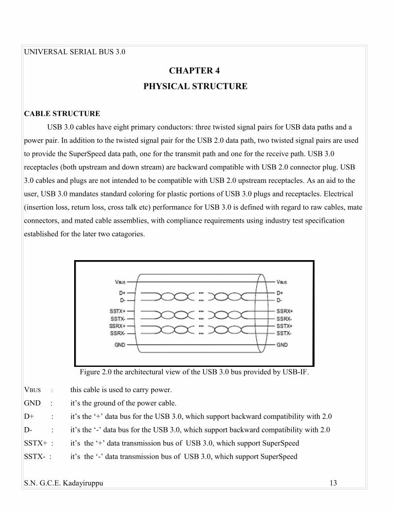
CABLE STRUCTURE
USB 3.0 cables have eight primary conductors: three twisted signal pairs for USB data paths and a
power pair. In addition to the twisted signal pair for the USB 2.0 data path, two twisted signal pairs are used
to provide the SuperSpeed data path, one for the transmit path and one for the receive path. USB 3.0
receptacles (both upstream and down stream) are backward compatible with USB 2.0 connector plug. USB
3.0 cables and plugs are not intended to be compatible with USB 2.0 upstream receptacles. As an aid to the
user, USB 3.0 mandates standard coloring for plastic portions of USB 3.0 plugs and receptacles. Electrical
(insertion loss, return loss, cross talk etc) performance for USB 3.0 is defined with regard to raw cables, mate
connectors, and mated cable assemblies, with compliance requirements using industry test specification
established for the later two catagories.
Figure 2.0 the architectural view of the USB 3.0 bus provided by USB-IF. VBUS : this cable is used to carry power.
GND : it’s the ground of the power cable.
D+ : it’s the ‘+’ data bus for the USB 3.0, which support backward compatibility with 2.0
D- : it’s the ‘-’ data bus for the USB 3.0, which support backward compatibility with 2.0
SSTX+ : it’s the ‘+’ data transmission bus of USB 3.0, which support SuperSpeed
SSTX- : it’s the ‘-’ data transmission bus of USB 3.0, which support SuperSpeed
S.N. G.C.E. Kadayiruppu 13

UNIVERSAL SERIAL BUS 3.0
SSRX+ : it’s the ‘+’ data reception bus of USB 3.0, which support SuperSpeed
SSRX- : it’s the ‘-’ data reception bus of USB 3.0, which support SuperSpeed
Here the USB is using a differential pair data cables. The differential pair data cables are used to d
reduce the transmission error. The data to be transmitted is passed through an opamp and the inverse of the
data is produced. And then these two data are passed through the +, - lines provided. In USB 3.0 both
shielded and unshielded differential pair lines are used. Shielded for the SuperSpeed transmission and the
unshielded for the non-SuperSpeed.
CROSS SECTIONAL REVIEW
Figure 3.0 cross sectional view of USB 3.0 cables
S.N. G.C.E. Kadayiruppu 14

UNIVERSAL SERIAL BUS 3.0
Table 4.0 color codes wires.
CONNECTORS
The USB 3.0 specification defines the following connectors:
• USB 3.0 standard-A plug and receptacle
• USB 3.0 standard-B plug and receptacle
• USB 3.0 powered-B plug and receptacle
• USB 3.0 micro-B plug and receptacle
• USB 3.0 micro-A plug
• USB 3.0 micro-AB receptacle
RECEPTACLE PLUG ACCEPTEDUSB 2.0 Standard-A USB 2.0 Standard-A or USB 3.0 Standard-AUSB 3.0 Standard-A USB 3.0 Standard-A or USB 2.0 Standard-AUSB 2.0 Standard-B USB 2.0 Standard-BUSB 3.0 Standard-B USB 3.0 Standard-B or USB 2.0 Standard-BUSB 3.0 Powered-B USB 3.0 Powered-B, USB 3.0 Standard B,
USB 2.0 Standard-BUSB 2.0 Micro-B USB 2.0 Micro-BUSB 3.0 Micro-B USB 3.0 Micro-B or USB 2.0 Micro-BUSB 2.0 Micro-AB USB 2.0 Micro-B or USB 2.0 Micro-AUSB 3.0 Micro-AB USB 3.0 Micro-B, USB 3.0 Micro-A
USB 2.0 Micro-B, or USB 2.0 Micro-Atable 5.0 plug accepted by Receptacles
S.N. G.C.E. Kadayiruppu 15
PINNO
COLOUR DESCRIPTION
1 RED POWER2 GREEN USB 3.0 DATA+3 WHITE USB 3.0 DATA-4 BLACK GROUND5 ORANGE SUPER SPEED RECEIVER-6 VIOLET SUPER SPEED RECEIVER+7 BLACK GROUND USB 3.08 GREEN SUPER SPEED TRANSMITTER-9 BLUE SUPER SPEED TRANSMITTER+

UNIVERSAL SERIAL BUS 3.0
STANDARD A TYPE CONNECTOR
USB3_RX : +/- data bus for reception USB 3.0
USB3_TX : +/- data bus for transmission USB 3.0
-D/+D : +/- data bus for USB 2.0
VBUS : Carry power
GND : Ground
Figure 6.0 diagram type A connector
S.N. G.C.E. Kadayiruppu 16

UNIVERSAL SERIAL BUS 3.0
CHAPTER 5 FEATURES
TRANSFER RATES
A USB supports following data rates:
• A low speed rate of 1.5 Mbit/s (187.5 kB/s) is defined by USB 1.0. It is very similar to full speed
operation except each bit takes 8 times as long to transmit. It is intended primarily to save cost in low-
bandwidth human interface devices (HID) such as keyboards, mice, and joysticks.
• The full speed rate of 12 Mbit/s (1.5 MB/s) is the basic USB data rate defined by USB 1.1. All USB
hubs support full speed.
• A high-speed (USB 2.0) rate of 480 Mbit/s (60 MB/s) was introduced in 2001. All high-speed devices
are capable of falling back to full-speed operation if necessary.
• A SuperSpeed (USB 3.0) rate of 5.0 Gbit/s (625 MB/s). The USB 3.0 specification was released by
Intel and its partners in August 2008
BACKWARD COMPATIBILITY
To accommodate the additional pins for SuperSpeed mode, the physical form factors for USB 3.0
plugs and receptacles have been modified from those used in previous versions. Standard-A cables have
extended heads where the SuperSpeed connectors extend beyond and slightly above the legacy connectors.
Similarly, the Standard-A receptacle is deeper to accept these new connectors. A legacy Standard-A cable
will operate as intended and will never interact with the SuperSpeed connectors, ensuring backward
compatibility. The Standard-B modifications could not be made as elegantly; the SuperSpeed connectors had
to be placed on top of the existing form factor, making legacy Standard-B plugs workable on SuperSpeed
Standard-B receptacles, but not vice versa.
POWER SPECIFICATIONS
S.N. G.C.E. Kadayiruppu 17

UNIVERSAL SERIAL BUS 3.0
The bus power spec has been increased so that a unit load is 150mA (+50% over minimum using USB
2.0). An unconfigured device can still draw only 1 unit load, but a configured device can draw up to 6 unit
loads (900mA, an 80% increase over USB 2.0 at a registered maximum of 500mA). Minimum device
operating voltage is dropped from 4.4V to 4V.
CABLE LENGTH
USB 3.0 does not define cable assembly lengths, except that it can be of any length as long as it meets
all the requirements defined in the specification. However, electronicdesign.com estimates cables will be
limited to 3 m at SuperSpeed.
TRANSFER MODE
When operating in SuperSpeed mode, full-duplex signaling occurs over 2 differential pairs separate
from the non-SuperSpeed differential pair. Full-duplex means that the data can be transferred in two
directions simultaneously.
OTHER FEATURES
• New power management features include support of idle, sleep and suspend states, as well as Link-,
Device-, and Function-level power management.
• Technology is similar to a single channel (1x) of PCI Express 2.0 (5-Gbit/s). It
uses 8B10B encoding, linear feedback shift register (LFSR) scrambling for data, spread spectrum. It
forces receivers to use low frequency periodic signaling (LFPS), dynamic equalization, and training
sequences to ensure fast signal locking.
• USB 3.0 extends the bulk transfer type in SuperSpeed with Streams. This extension allows a host and
device to create and transfer multiple streams of data through a single bulk pipe
• SuperSpeed establishes a communications pipe between the host and each device, in a host-directed
protocol. In contrast, USB 2.0 broadcasts packet traffic to all devices.
• As its ancestors USB 3.0 support hot swapping. That is the USB cables can be connected and operated
without rebooting the computer.
• As its ancestors USB 3.0 networks use a tiered-star topology
S.N. G.C.E. Kadayiruppu 18

UNIVERSAL SERIAL BUS 3.0
• The USB standard specifies relatively loose tolerances for compliant USB connectors, intending to
minimize incompatibilities in connectors produced by different vendors (a goal that has been very
successfully achieved). Unlike most other connector standards, the USB specification also defines
limits to the size of a connecting device in the area around its plug. This was done to prevent a device
from blocking adjacent ports due to its size. Compliant devices must either fit within the size
restrictions or support a compliant extension cable which does.
• The connectors are designed to be robust. Many previous connector designs were fragile, with pins or
other delicate components prone to bending or breaking, even with the application of only very
modest force. The electrical contacts in a USB connector are protected by an adjacent plastic tongue,
and the entire connecting assembly is usually further protected by an enclosing metal sheath. As a
result USB connectors can safely be handled, inserted, and removed, even by a young child.
• It is difficult to attach a USB connector incorrectly. Connectors cannot be plugged in upside down,
and it is clear from the appearance and kinesthetic sensation of making a connection when the plug
and socket are correctly mated. However, it is not obvious at a glance to the inexperienced user (or to
a user without sight of the installation) which way around the connector goes, thus it is often
necessary to try both ways. More often than not, however, the side of the connector with the trident
logo should be on top or towards the user.
• USB communication takes the form of packets. Initially, all packets are sent from the host, via the
root hub and possibly more hubs, to devices. Some of those packets direct a device to send some
packets in reply.
S.N. G.C.E. Kadayiruppu 19

UNIVERSAL SERIAL BUS 3.0
CHAPTER 6COMPARISONS
USB 3.0 WITH FIREWIRE
The firewire is the industrial name of the cable standard called IEEE 1394. S3200 is the upcoming
product in this series. Any common computer users might never see a FireWire cable; professionals and Mac
owners tend to be more familiar with the technology. Right now, there are two versions of FireWire in use;
FireWire 400 and 800. If you’re catching on to the number scheme by now, you might guess that FireWire
400 transfers at 400 Mbps and 800 transfers at 800 Mbps. The comparison between the USB 3.0 and the
FireWire is made below.
• USB 3.0 promises a data transfer rate of 4.8 Gbps, where FireWire 3200 promises to deliver 3.2 Gbps.
FireWire 3200 has a maximum capability of a 3.2Gbps transfer rate, which is 1.6Gbps slower than
USB 3.0
• FireWire 400 is easier to find than FireWire 800 (except on Macs), and the number of available ports
is typically limited to 1-2, even on a high-end motherboard. USB 2.0 ports, on the other hand, are
plentiful, with most boards offering 8-12 in some combination of included ports and onboard headers.
• The firewire is capable to deliver more power on a single cable than the USB 3.0.
• FireWire has always been the more technologically-advanced standard, with its faster transfer speeds,
lower CPU utilization, and the ability to provide more power to attached devices (devices that can run
off a single FireWire port could well require two USB ports). These advantages, however, have never
managed to overcome USB 2.0's general popularity, and FireWire remains a niche interface outside
certain peripheral markets (i.e., video cameras), where it has always done well, and Macintosh
computers.
• The wide popularity and simplicity of the USB series are capable of suppressing the S3200. The main
reason is that the Firewire is generally seen only in the Mac computers, so the Firewire is not much
popular among the normal users.
S.N. G.C.E. Kadayiruppu 20

UNIVERSAL SERIAL BUS 3.0
• The new S1600/S3200 cables will be fully compatible with both older FireWire 800 cables and
FireWire 400/800 devices. Like wise the USB 3.0 cables will also be compatible with the old USB 2.0
versions.
• One of the other advantages of USB 3.0 over the Firewire is that the USB ports are available in all
standard motherboards in 6-12 numbers. They don’t need any add on cards for that. But when we take
the case of the Firewire they need add on card to support. And also they are not popular in the
ordinary motherboards.
• The USB 3.0 is supporting master-slave architecture while the Firewire is supporting a peer-to-peer
architecture.
• USB has two key things going for it though – it’s cheaper and more popular – which means it’s easier
to buy (for your wallet) and easier to use (for your mainstream devices). FireWire has long been
supported by Apple, whereas USB has been found in most Microsoft machines, and the difference
reminds me a lot of the difference between the two companies
USB 3.0 WITH USB 2.0
As we know the USB 3.0 is the next version of the USB series. So we cant expect anything other than
advantages from USB 3.0 over 2.0. Still we perform a comparison to find out what are advantages which we
can expect from the new SuperSpeed USB (USB 3.0).
• The new spec will support data transfers at 4.8 gigabits per second, or Gbps, nearly 10 times faster
than the current standard’s 480 megabits per second and six times faster than FireWire 800. It’s also
400 times faster than the 12 Mbps offered by the original spec, USB 1.0.To get a sense of the speed
increase, consider this: Under USB 2.0 it takes about 10 minutes to transfer a high-def video from a
Blu-ray disc. With USB 3.0, it will take just about a minute.
• USB 2.0 is also known as "Hi-Speed USB," while USB 3.0 will have the confusingly similar moniker
"SuperSpeed USB."
• The new USB 3.0 connectors and devices will be compatible with older USB ports (on devices using
USB 2.0 and 1.0) but they will be limited to the older ports’ slower speeds. The latest SuperSpeed
S.N. G.C.E. Kadayiruppu 21

UNIVERSAL SERIAL BUS 3.0
USB-enabled devices connecting to older PCs running USB 2.0 or lower will experience data transfer
rates that are much slower.
• USB 2.0 uses a polling-based architecture, which means the host computer has to constantly check the
bus to see if any devices are attached and if so, whether they are doing anything. As a result, that
keeps the host computer busy, drawing power even when it’s not needed. It’s a problem when you
attach a USB device to a laptop running on battery. USB 3.0 offers better specifications for power
management. USB 3.0 will move to an interrupt-driven architecture where your PC can ignore the
connected device till the latter actually does something. That can really lower the power consumption.
• It also has better power output, 900 milliamps compared to 100 milliamps with USB 2.0. That means
up to four devices can be charged from a single USB port and charged faster.
• When we look to the architecture of the USB 3.0, unlike the USB 2.0, USB 3.0 support 9 pins instead
of 5 pins.
• The USB 3.0 support full-duplex data transfer. The full duplex means you can send data in either
direction (bi-directionally) simultaneously. But USB 2.0 was supporting half-duplex transmission that
you can transmit the data in either direction but not simultaneously.
• The main change the users can observe is coming in the inner side of the USB 3.0. The USB 2.0’s
inner side was appeared to be in gray or black, it appeared even white in some time. But the USB
3.0’s inner side will be in blue.
• Since the USB 3.0 is supporting more cables than USB 2.0 the cable will be appeared a little much
thick for the users.
• When we look at the length supported by each one USB 2.0 was supporting about 5 meters USB 3.0
will be supporting about 3 meters.
CHAPTER 7APPLICATIONS
The USB ports are used for a number of applications. The USB ports get the popularity because of its
simplicity as well the easiness in use. The main application of USB 3.0 is listed below.
S.N. G.C.E. Kadayiruppu 22

UNIVERSAL SERIAL BUS 3.0
• USB implements connections to storage devices using a set of standards called the USB mass storage
device class (referred to as MSC or UMS). This was initially intended for traditional magnetic and
optical drives, but has been extended to support a wide variety of devices, particularly flash drives.
This generality is because many systems can be controlled with the familiar idiom of file manipulation
within directories (The process of making a novel device look like a familiar device is also known as
extension)
• USB 3.0 can also support portable hard disk drives. The earlier versions of USBs were not supporting
the 3.5 inch hard disk drives. Originally conceived and still used today for optical storage devices
(CD-RW drives, DVD drives, etc.), a number of manufacturers offer external portable USB hard
drives, or empty enclosures for drives, that offer performance comparable to internal drives[citation
needed]. These external drives usually contain a translating device that interfaces a drive of
conventional technology (IDE, ATA, SATA, ATAPI, or even SCSI) to a USB port. Functionally, the
drive appears to the user just like an internal drive.
• These are used to provide power for low power consuming devises. These can be used for charging
the mobile phones.
• Though most newer computers are capable of booting off USB Mass Storage devices, USB is not
intended to be a primary bus for a computer's internal storage: buses such as ATA (IDE), Serial ATA
(SATA), and SCSI fulfill that role. However, USB has one important advantage in that it is possible to
install and remove devices without opening the computer case, making it useful for external drives.
• Mice and keyboards are frequently fitted with USB connectors, but because most PC motherboards
still retain PS/2 connectors for the keyboard and mouse as of 2007, they are often supplied with a
small USB-to-PS/2 adaptor, allowing usage with either USB or PS/2 interface. There is no logic
inside these adaptors: they make use of the fact that such HID interfaces are equipped with controllers
that are capable of serving both the USB and the PS/2 protocol, and automatically detect which type
of port they are plugged into. Joysticks, keypads, tablets and other human-interface devices are also
progressively migrating from MIDI, PC game port, and PS/2 connectors to USB.
• It can also support Ethernet adapter, modem, serial port adapter etc
• It can support Full speed hub, hi-speed hub, and SuperSpeed hub.
S.N. G.C.E. Kadayiruppu 23

UNIVERSAL SERIAL BUS 3.0
• It can support USB smart card reader, USB compliance testing devices, Wi-Fi adapter,
Bluetooth adapter, ActiveSync device, Force feedback joystick
S.N. G.C.E. Kadayiruppu 24

UNIVERSAL SERIAL BUS 3.0
CHAPTER 8CONCLUSION
The Universal serial bus 3.0 is supporting a speed of about 5 Gb/sec ie ten times faster than the 2.0
version. And it is also faster than the new Firewire product S3200. So hopefully by the help of this
SuperSpeed data transfer rate the USB 3.0 will be replacing many of the connecters in the future. The
prototype of the USB 3.0 was already implemented by ASUSE in their motherboard. The drivers for the
USB 3.0 are made available to the opensource Linux. The Linux kernel will support USB 3.0 with version
2.6.31, which will be released around August. Because of the backward compatibility of the USB 3.0 the
devises which we are using now and the ports we are using now(which is USB 2.0) will be working proper
with the new USB 3.0 devises and ports. Consumer products are expected to become available in 2010.
Commercial controllers are expected to enter into volume production no later than the first quarter of 2010.
REFERENCE
S.N. G.C.E. Kadayiruppu 25

UNIVERSAL SERIAL BUS 3.0
USB 3.0 specifications released by USB consortium
Chip magazine 06/2009
http://www.reghardware.co.uk/2009/05/25/superspeed_usb_3_guide
http://en.wikipedia.org/wiki/Universal_Serial_bus
http://www.usb.org/developers/docs
http://www.wired.com/gadgetlab/2008/11/superspeed-us-1
http://tech.blorge.com
http://www.interfacebus.com
S.N. G.C.E. Kadayiruppu 26