Embed Size (px)
Citation preview
The Ultimate Guide to Stereolithography (SLA) 3D printingStereolithography (SLA) is an additive manufacturing — commonly referred to
as 3D printing — technology that converts liquid materials into solid parts, layer
by layer, by selectively curing them using a light source in a process called
photopolymerization. SLA is widely used to create models, prototypes, patterns,
and production parts for a range of industries from engineering and product
design to manufacturing, dentistry, jewelry, model making, and education.
In this comprehensive guide, you’ll learn about the different SLA systems, various
materials and their characteristics, and how SLA compares to other technologies
on the market.
March 2017 | formlabs.com
Table of Contents Brief History . . . . . . . . . . . . . . . . . . . . . . 3SLA Systems . . . . . . . . . . . . . . . . . . . . . . . . 4 Right-Side Up SLA . . . . . . . . . . . . . . . . . . . 4 Upside-Down (Inverted) SLA . . . . . . . . . . . . . . 5 Understanding Supports . . . . . . . . . . . . . . . . 6 Comparison of SLA systems . . . . . . . . . . . . . . 7Materials . . . . . . . . . . . . . . . . . . . . . . . . . . 8 The Polymerization Process . . . . . . . . . . . . . . 8 Characteristics of Resins and Plastics . . . . . . . . . . 9 Composition of Photopolymet Resin . . . . . . . .10 Isotropy vs. Anisotropy . . . . . . . . . . . . . . . . .10 Post-Curing . . . . . . . . . . . . . . . . . . . . . .10 Thermosettings vs. Thermoplastics . . . . . . . . . . . 11 SLA Materials by Application . . . . . . . . . . . . . .12 Standard . . . . . . . . . . . . . . . . . . . . .12 Engineering. . . . . . . . . . . . . . . . . . . .12 Dental . . . . . . . . . . . . . . . . . . . . . .13 Jewelry . . . . . . . . . . . . . . . . . . . . . .13 Experimental . . . . . . . . . . . . . . . . . . .14Why Desktop SLA?. . . . . . . . . . . . . . . . . . . . . .15 High Resolution and Smooth Surface Finish . . . .15 Accuracy and Repeatability . . . . . . . . . . . .16 Design Freedom . . . . . . . . . . . . . . . . .16 Rapid Prototyping . . . . . . . . . . . . . . . . . 17 Functional Parts for a Wide Range of Applications .18 Costs and Value . . . . . . . . . . . . . . . . .19Printing Process . . . . . . . . . . . . . . . . . . . . . . 20 Design . . . . . . . . . . . . . . . . . . . . . 20 Prepare . . . . . . . . . . . . . . . . . . . . 20 Print . . . . . . . . . . . . . . . . . . . . . . .21 Clean. . . . . . . . . . . . . . . . . . . . . . .21 Cure . . . . . . . . . . . . . . . . . . . . . . 22 Finish. . . . . . . . . . . . . . . . . . . . . . 22Get Started with SLA 3D Printing . . . . . . . . . . . . . . 23
THE ULTIMATE GUIDE TO STEREOLITHOGRAPHY (SLA) 3D PRINTING 3
Brief HistoryThe SLA process first appeared in the early 1970s, when Japanese researcher
Dr. Hideo Kodama invented the modern layered approach to stereolithography of
using ultraviolet light to cure photosensitive polymers. The term stereolithography
itself was coined by Charles (Chuck) W. Hull, who patented the technology in 1986
and founded the company 3D Systems to commercialize it. Hull described the
method as creating 3D objects by successively “printing” thin layers of a material
curable by ultraviolet light, starting from the bottom layer to the top layer. Later,
the definition was extended to any material capable of solidification or alteration
of its physical state.
Today, 3D printing and additive manufacturing (AM) describe numerous individual
processes, which vary in their method of layer manufacturing, material, and
machine technology used.
As patents began to expire at the end of the 2000s, the introduction of desktop
3D printing widened access to the technology, with fused deposition modeling
(FDM) first gaining adoption in desktop platforms. While this affordable extrusion-
based technology aided the widespread use of 3D printing, the quality of these
parts has limited the use of these machines, since repeatable, high-precision
results are crucial for professional applications.
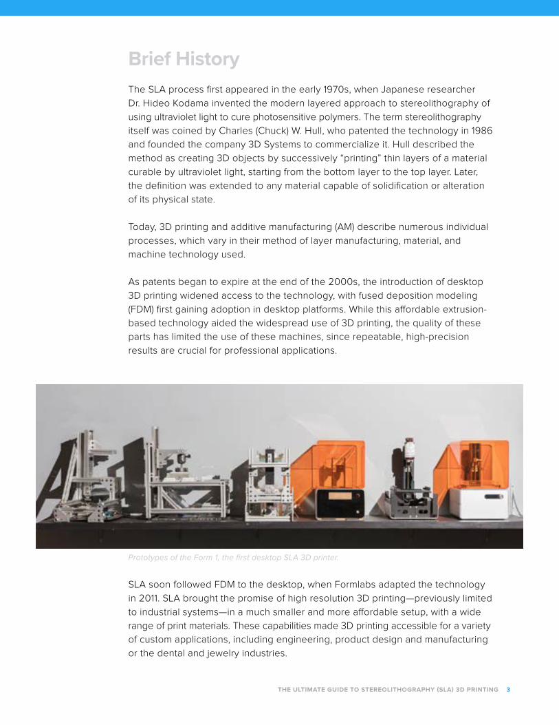
Prototypes of the Form 1, the first desktop SLA 3D printer.
SLA soon followed FDM to the desktop, when Formlabs adapted the technology
in 2011. SLA brought the promise of high resolution 3D printing—previously limited
to industrial systems—in a much smaller and more affordable setup, with a wide
range of print materials. These capabilities made 3D printing accessible for a variety
of custom applications, including engineering, product design and manufacturing
or the dental and jewelry industries.
SLA SystemsSLA belongs to a family of additive manufacturing technologies known as vat
photopolymerization. These machines are all built around the same principle,
using a light source—UV laser or projector—to cure liquid resin into hardened
plastic. The main physical differentiation lies in the arrangement of the core
components, such as the light source, the build platform, and the resin tank.
RIGHT-SIDE SLA
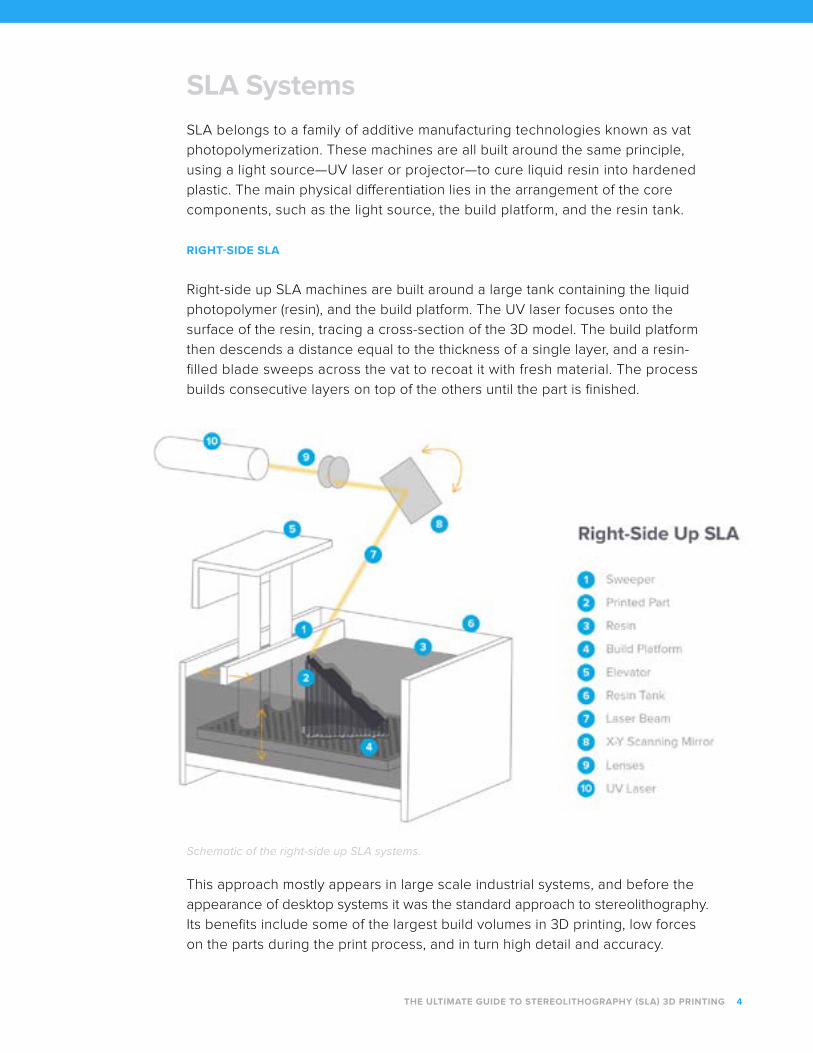
Right-side up SLA machines are built around a large tank containing the liquid
photopolymer (resin), and the build platform. The UV laser focuses onto the
surface of the resin, tracing a cross-section of the 3D model. The build platform
then descends a distance equal to the thickness of a single layer, and a resin-
filled blade sweeps across the vat to recoat it with fresh material. The process
builds consecutive layers on top of the others until the part is finished.
Schematic of the right-side up SLA systems.
This approach mostly appears in large scale industrial systems, and before the
appearance of desktop systems it was the standard approach to stereolithography.
Its benefits include some of the largest build volumes in 3D printing, low forces
on the parts during the print process, and in turn high detail and accuracy.
THE ULTIMATE GUIDE TO STEREOLITHOGRAPHY (SLA) 3D PRINTING 4
Due to the large setup, maintenance requirements, and material volume, right-side
up SLA requires a high initial investment and is expensive to run. The entire build
area must be filled with resin, which can easily mean 10-100+ liters in raw material,
making it a time consuming task to handle, maintain, filter and swap materials.
These machines are highly sensitive to being stable and level, any inconsistency
can lead to the recoater toppling the part, leading to print failure.
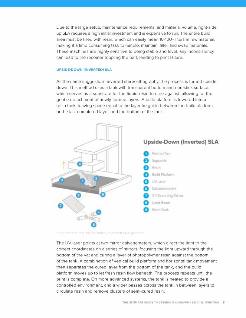
UPSIDE-DOWN (INVERTED) SLA
As the name suggests, in inverted stereolithography, the process is turned upside
down. This method uses a tank with transparent bottom and non-stick surface,
which serves as a substrate for the liquid resin to cure against, allowing for the
gentle detachment of newly-formed layers. A build platform is lowered into a
resin tank, leaving space equal to the layer height in between the build platform,
or the last completed layer, and the bottom of the tank.
Schematic of the upside-down (inverted) SLA systems
The UV laser points at two mirror galvanometers, which direct the light to the
correct coordinates on a series of mirrors, focusing the light upward through the
bottom of the vat and curing a layer of photopolymer resin against the bottom
of the tank. A combination of vertical build platform and horizontal tank movement
then separates the cured layer from the bottom of the tank, and the build
platform moves up to let fresh resin flow beneath. The process repeats until the
print is complete. On more advanced systems, the tank is heated to provide a
controlled environment, and a wiper passes across the tank in between layers to
circulate resin and remove clusters of semi-cured resin.
THE ULTIMATE GUIDE TO STEREOLITHOGRAPHY (SLA) 3D PRINTING 5
An advantage of this upside-down approach is that the build volume can substantially
exceed the volume of the tank, since the machine only requires enough material
to keep the bottom of the build vat continuously covered with liquid. This makes
it generally easier to maintain, clean, swap materials, and also allows for a much
smaller machine size and lower cost, making it possible to bring SLA to the desktop.
Inverted SLA comes with its own set of limitations. Due to the peel forces affecting
the print when it’s separated from the surface of the tank, the build volume is
limited, and larger support structures are required to keep the part attached to
the build platform. Peel forces also limit the use of more flexible materials —
Shore hardness below ~70A, because the support structures become flexible as well.
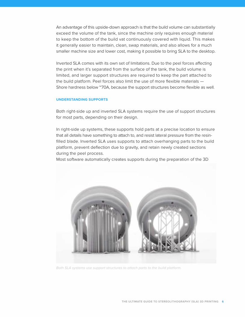
UNDERSTANDING SUPPORTS
Both right-side up and inverted SLA systems require the use of support structures
for most parts, depending on their design.
In right-side up systems, these supports hold parts at a precise location to ensure
that all details have something to attach to, and resist lateral pressure from the resin-
filled blade. Inverted SLA uses supports to attach overhanging parts to the build
platform, prevent deflection due to gravity, and retain newly created sections
during the peel process.
Most software automatically creates supports during the preparation of the 3D
THE ULTIMATE GUIDE TO STEREOLITHOGRAPHY (SLA) 3D PRINTING 6
Both SLA systems use support structures to attach parts to the build platform.
models, but they can also be adjusted manually. Once the printing process is
completed, these supports must be removed from the finished product manually.
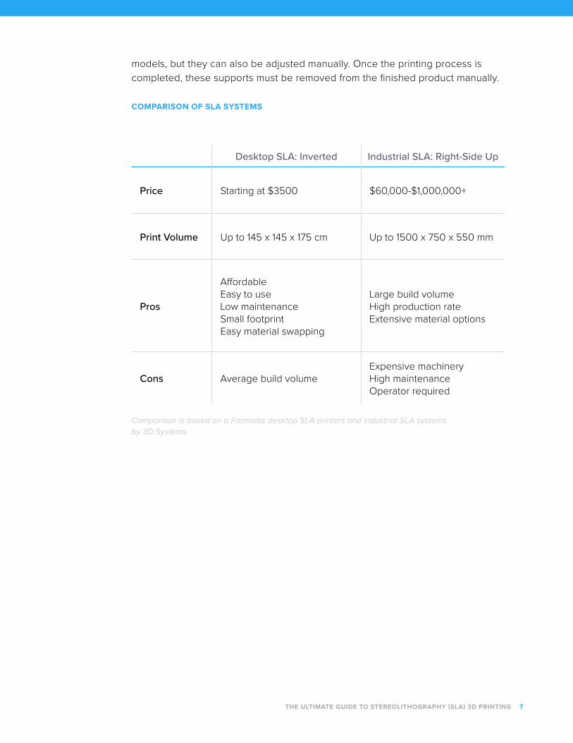
COMPARISON OF SLA SYSTEMS
Desktop SLA: Inverted Industrial SLA: Right-Side Up
Price Starting at $3500 $60,000-$1,000,000+
Print Volume Up to 145 x 145 x 175 cm Up to 1500 x 750 x 550 mm
Pros
AffordableEasy to useLow maintenanceSmall footprintEasy material swapping
Large build volumeHigh production rateExtensive material options
Cons Average build volumeExpensive machineryHigh maintenanceOperator required
THE ULTIMATE GUIDE TO STEREOLITHOGRAPHY (SLA) 3D PRINTING 7
Comparison is based on a Formlabs desktop SLA printers and industrial SLA systems by 3D Systems.
MaterialsSLA 3D printers provide the tool, but it’s the materials that empower stereolithography
to create a wide range of functional parts for different industries. In this chapter,
we’ll look into the photopolymerization process and its raw material, the resin, from
its unique characteristics to the various compositions for specific applications.
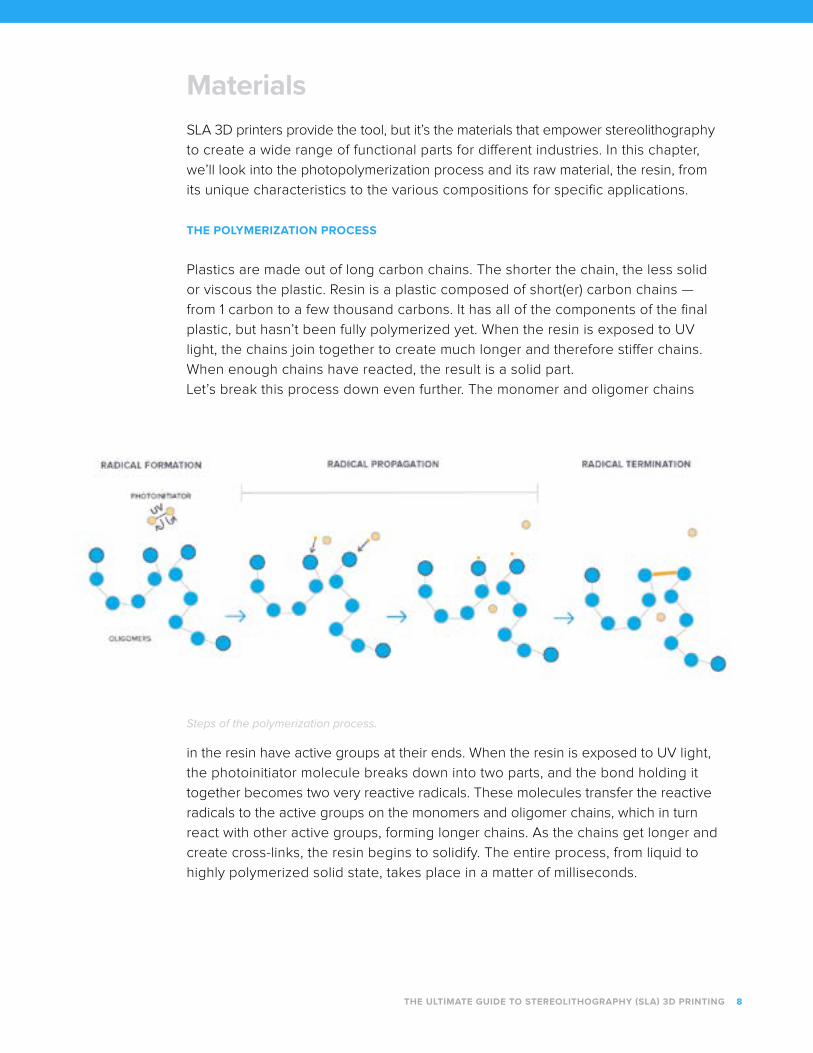
THE POLYMERIZATION PROCESS
Plastics are made out of long carbon chains. The shorter the chain, the less solid
or viscous the plastic. Resin is a plastic composed of short(er) carbon chains —
from 1 carbon to a few thousand carbons. It has all of the components of the final
plastic, but hasn’t been fully polymerized yet. When the resin is exposed to UV
light, the chains join together to create much longer and therefore stiffer chains.
When enough chains have reacted, the result is a solid part.
Let’s break this process down even further. The monomer and oligomer chains
Steps of the polymerization process.
in the resin have active groups at their ends. When the resin is exposed to UV light,
the photoinitiator molecule breaks down into two parts, and the bond holding it
together becomes two very reactive radicals. These molecules transfer the reactive
radicals to the active groups on the monomers and oligomer chains, which in turn
react with other active groups, forming longer chains. As the chains get longer and
create cross-links, the resin begins to solidify. The entire process, from liquid to
highly polymerized solid state, takes place in a matter of milliseconds.
THE ULTIMATE GUIDE TO STEREOLITHOGRAPHY (SLA) 3D PRINTING 8
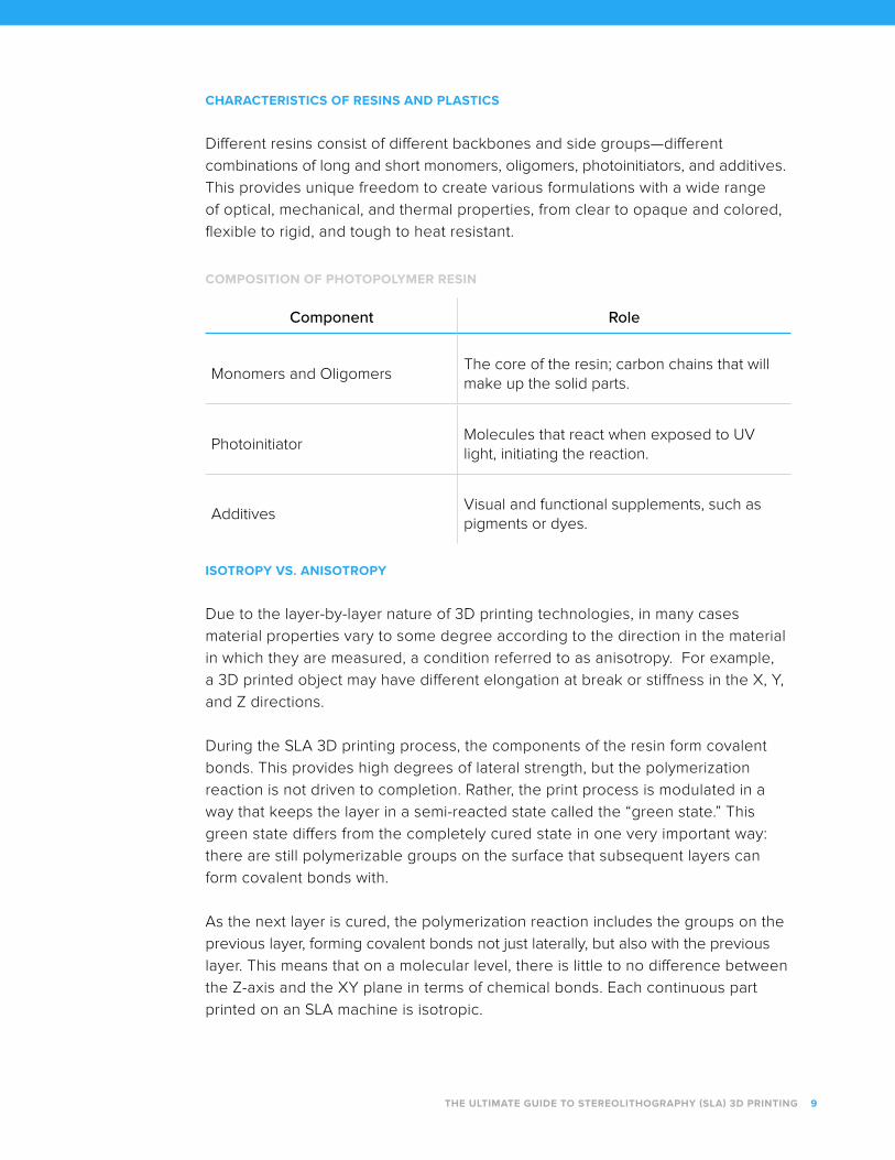
CHARACTERISTICS OF RESINS AND PLASTICS
Different resins consist of different backbones and side groups—different
combinations of long and short monomers, oligomers, photoinitiators, and additives.
This provides unique freedom to create various formulations with a wide range
of optical, mechanical, and thermal properties, from clear to opaque and colored,
flexible to rigid, and tough to heat resistant.
COMPOSITION OF PHOTOPOLYMER RESIN
Component Role
Monomers and OligomersThe core of the resin; carbon chains that will make up the solid parts.
PhotoinitiatorMolecules that react when exposed to UV light, initiating the reaction.
AdditivesVisual and functional supplements, such as pigments or dyes.
ISOTROPY VS. ANISOTROPY
Due to the layer-by-layer nature of 3D printing technologies, in many cases
material properties vary to some degree according to the direction in the material
in which they are measured, a condition referred to as anisotropy. For example,
a 3D printed object may have different elongation at break or stiffness in the X, Y,
and Z directions.
During the SLA 3D printing process, the components of the resin form covalent
bonds. This provides high degrees of lateral strength, but the polymerization
reaction is not driven to completion. Rather, the print process is modulated in a
way that keeps the layer in a semi-reacted state called the “green state.” This
green state differs from the completely cured state in one very important way:
there are still polymerizable groups on the surface that subsequent layers can
form covalent bonds with.
As the next layer is cured, the polymerization reaction includes the groups on the
previous layer, forming covalent bonds not just laterally, but also with the previous
layer. This means that on a molecular level, there is little to no difference between
the Z-axis and the XY plane in terms of chemical bonds. Each continuous part
printed on an SLA machine is isotropic.
THE ULTIMATE GUIDE TO STEREOLITHOGRAPHY (SLA) 3D PRINTING 9
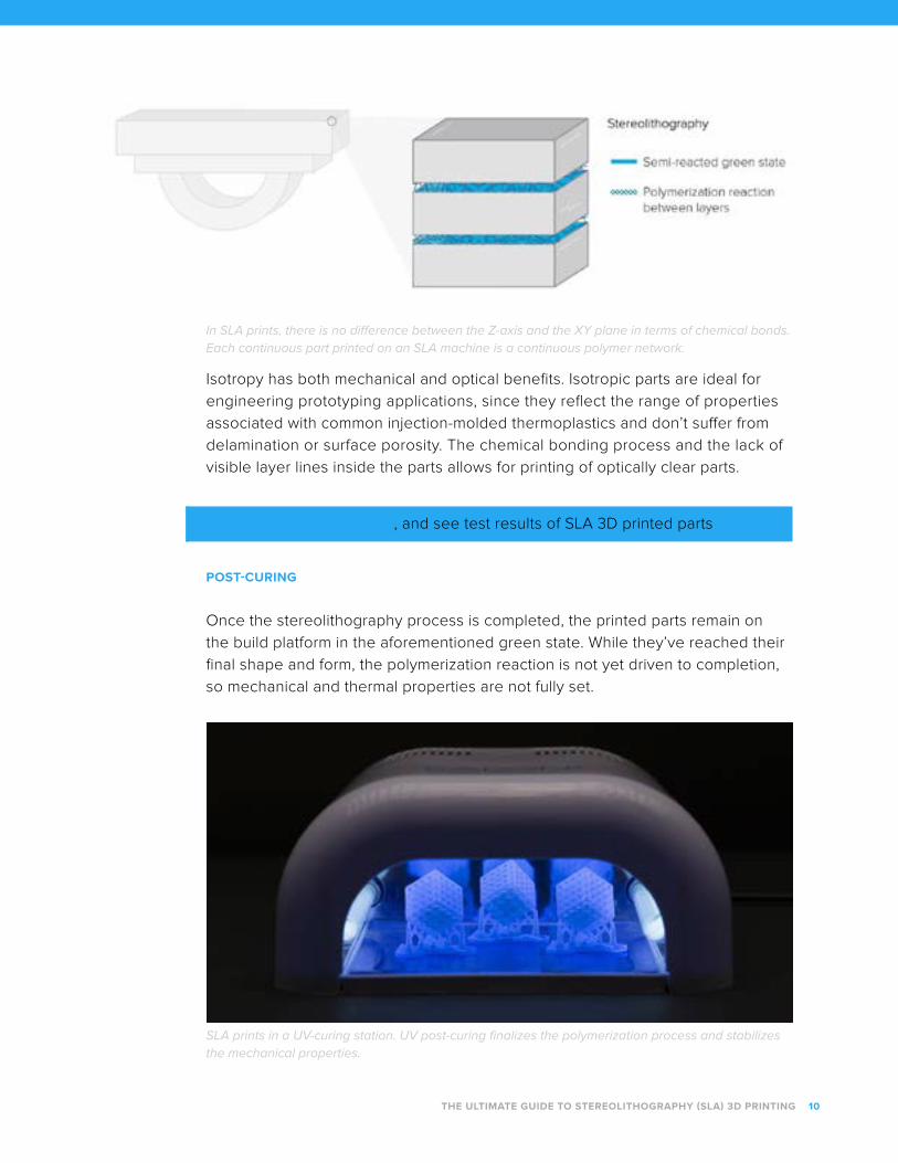
In SLA prints, there is no difference between the Z-axis and the XY plane in terms of chemical bonds. Each continuous part printed on an SLA machine is a continuous polymer network.
Isotropy has both mechanical and optical benefits. Isotropic parts are ideal for
engineering prototyping applications, since they reflect the range of properties
associated with common injection-molded thermoplastics and don’t suffer from
delamination or surface porosity. The chemical bonding process and the lack of
visible layer lines inside the parts allows for printing of optically clear parts.
Learn more about isotropy, and see test results of SLA 3D printed parts
POST-CURING
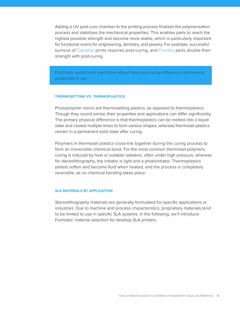
Once the stereolithography process is completed, the printed parts remain on
the build platform in the aforementioned green state. While they’ve reached their
final shape and form, the polymerization reaction is not yet driven to completion,
so mechanical and thermal properties are not fully set.
SLA prints in a UV-curing station. UV post-curing finalizes the polymerization process and stabilizes the mechanical properties.
THE ULTIMATE GUIDE TO STEREOLITHOGRAPHY (SLA) 3D PRINTING 10
THE ULTIMATE GUIDE TO STEREOLITHOGRAPHY (SLA) 3D PRINTING 11
Adding a UV post-cure chamber to the printing process finalizes the polymerization
process and stabilizes the mechanical properties. This enables parts to reach the
highest possible strength and become more stable, which is particularly important
for functional resins for engineering, dentistry, and jewelry. For example, successful
burnout of Castable prints requires post-curing, and Flexible parts double their
strength with post-curing.
Find tests results and read more about how post-curing influences mechanical
properties in our white paper.
THERMOSETTING VS. THERMOPLASTICS
Photopolymer resins are thermosetting plastics, as opposed to thermoplastics.
Though they sound similar, their properties and applications can differ significantly.
The primary physical difference is that thermoplastics can be melted into a liquid
state and cooled multiple times to form various shapes, whereas thermoset plastics
remain in a permanent solid state after curing.
Polymers in thermoset plastics cross-link together during the curing process to
form an irreversible chemical bond. For the most common thermoset polymers,
curing is induced by heat or suitable radiation, often under high pressure, whereas
for stereolithography, the initiator is light and a photoinitiator. Thermoplastics
pellets soften and become fluid when heated, and the process is completely
reversible, as no chemical bonding takes place.
SLA MATERIALS BY APPLICATION
Stereolithography materials are generally formulated for specific applications or
industries. Due to machine and process characteristics, proprietary materials tend
to be limited to use in specific SLA systems. In the following, we’ll introduce
Formlabs’ material selection for desktop SLA printers.
Interchangeable lens camera, produced entirely using Standard Resins, including the optically transparent lenses. Learn how it’s made.
STANDARD
Compare Standard Resins
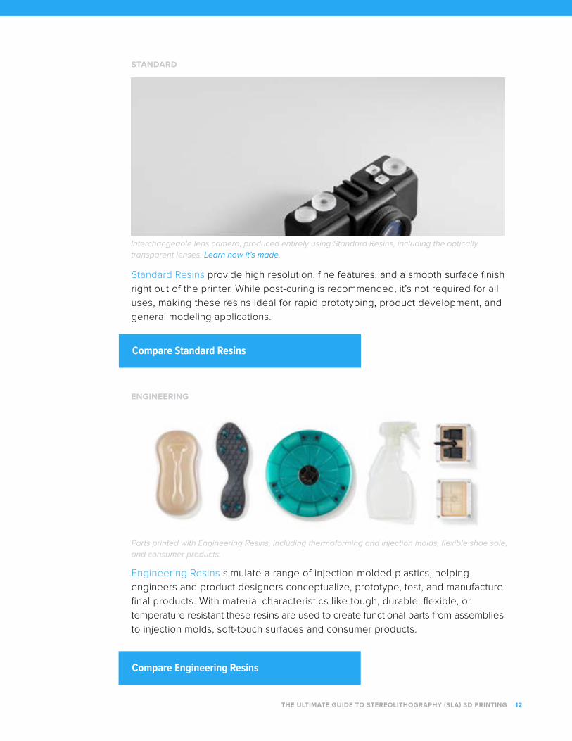
Parts printed with Engineering Resins, including thermoforming and injection molds, flexible shoe sole, and consumer products.
ENGINEERING
Engineering Resins simulate a range of injection-molded plastics, helping
engineers and product designers conceptualize, prototype, test, and manufacture
final products. With material characteristics like tough, durable, flexible, or
temperature resistant these resins are used to create functional parts from assemblies
to injection molds, soft-touch surfaces and consumer products.
Standard Resins provide high resolution, fine features, and a smooth surface finish
right out of the printer. While post-curing is recommended, it’s not required for all
uses, making these resins ideal for rapid prototyping, product development, and
general modeling applications.
Compare Engineering Resins
THE ULTIMATE GUIDE TO STEREOLITHOGRAPHY (SLA) 3D PRINTING 12
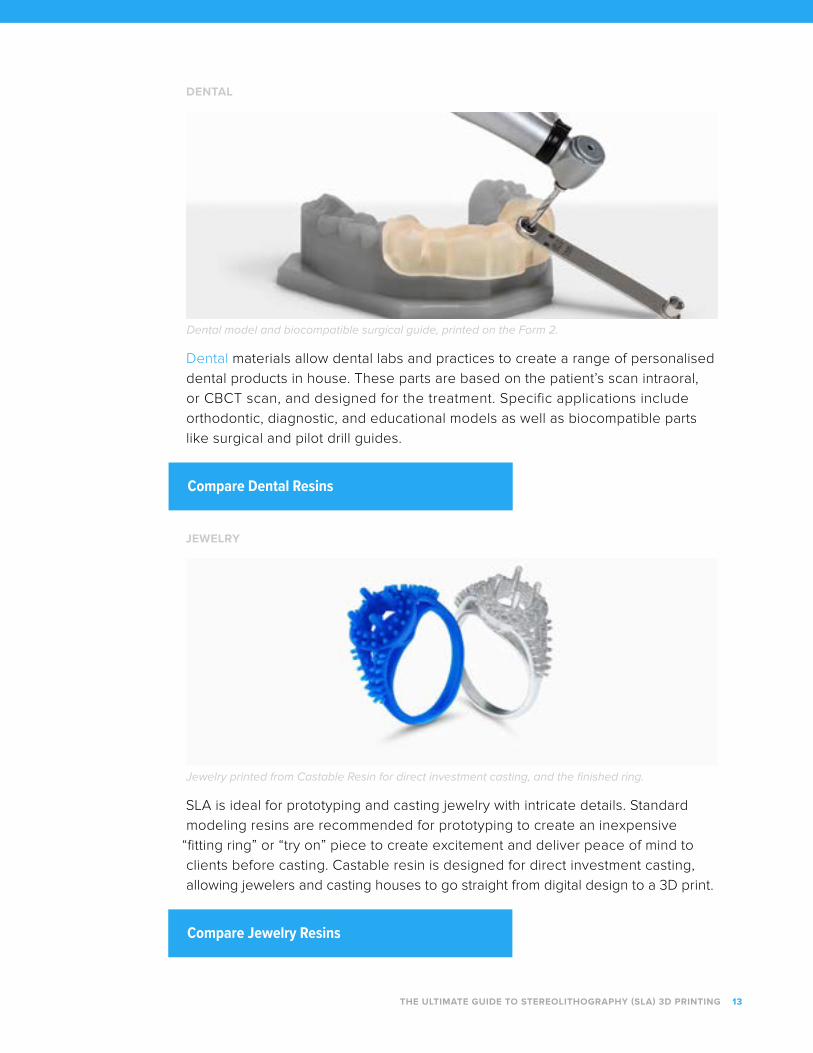
Dental model and biocompatible surgical guide, printed on the Form 2.
DENTAL
Dental materials allow dental labs and practices to create a range of personalised
dental products in house. These parts are based on the patient’s scan intraoral,
or CBCT scan, and designed for the treatment. Specific applications include
orthodontic, diagnostic, and educational models as well as biocompatible parts
like surgical and pilot drill guides.
Compare Dental Resins
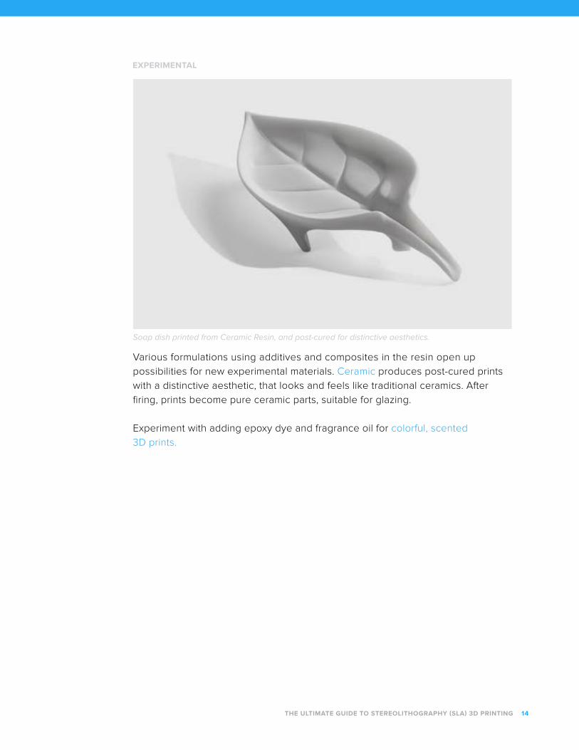
Jewelry printed from Castable Resin for direct investment casting, and the finished ring.
JEWELRY
SLA is ideal for prototyping and casting jewelry with intricate details. Standard
modeling resins are recommended for prototyping to create an inexpensive
“fitting ring” or “try on” piece to create excitement and deliver peace of mind to
clients before casting. Castable resin is designed for direct investment casting,
allowing jewelers and casting houses to go straight from digital design to a 3D print.
Compare Jewelry Resins
THE ULTIMATE GUIDE TO STEREOLITHOGRAPHY (SLA) 3D PRINTING 13
THE ULTIMATE GUIDE TO STEREOLITHOGRAPHY (SLA) 3D PRINTING 14
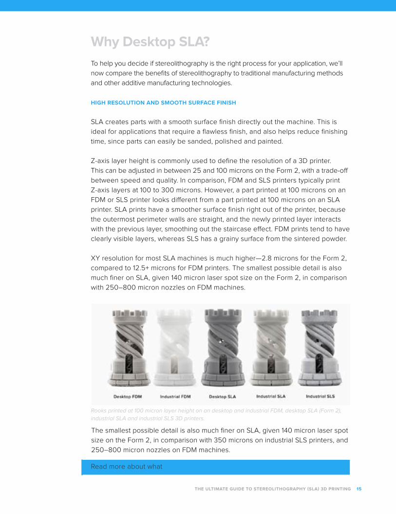
Soap dish printed from Ceramic Resin, and post-cured for distinctive aesthetics.
EXPERIMENTAL
Various formulations using additives and composites in the resin open up
possibilities for new experimental materials. Ceramic produces post-cured prints
with a distinctive aesthetic, that looks and feels like traditional ceramics. After
firing, prints become pure ceramic parts, suitable for glazing.
Experiment with adding epoxy dye and fragrance oil for colorful, scented
3D prints.
THE ULTIMATE GUIDE TO STEREOLITHOGRAPHY (SLA) 3D PRINTING 15
Why Desktop SLA?To help you decide if stereolithography is the right process for your application, we’ll
now compare the benefits of stereolithography to traditional manufacturing methods
and other additive manufacturing technologies.
HIGH RESOLUTION AND SMOOTH SURFACE FINISH
SLA creates parts with a smooth surface finish directly out the machine. This is
ideal for applications that require a flawless finish, and also helps reduce finishing
time, since parts can easily be sanded, polished and painted.
Z-axis layer height is commonly used to define the resolution of a 3D printer.
This can be adjusted in between 25 and 100 microns on the Form 2, with a trade-off
between speed and quality. In comparison, FDM and SLS printers typically print
Z-axis layers at 100 to 300 microns. However, a part printed at 100 microns on an
FDM or SLS printer looks different from a part printed at 100 microns on an SLA
printer. SLA prints have a smoother surface finish right out of the printer, because
the outermost perimeter walls are straight, and the newly printed layer interacts
with the previous layer, smoothing out the staircase effect. FDM prints tend to have
clearly visible layers, whereas SLS has a grainy surface from the sintered powder.
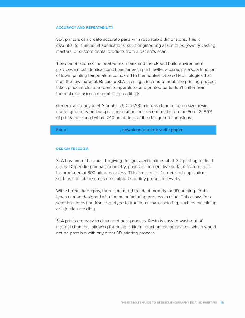
XY resolution for most SLA machines is much higher—2.8 microns for the Form 2,
compared to 12.5+ microns for FDM printers. The smallest possible detail is also
much finer on SLA, given 140 micron laser spot size on the Form 2, in comparison
with 250–800 micron nozzles on FDM machines.
Rooks printed at 100 micron layer height on an desktop and industrial FDM, desktop SLA (Form 2), industrial SLA and industrial SLS 3D printers.
The smallest possible detail is also much finer on SLA, given 140 micron laser spot
size on the Form 2, in comparison with 350 microns on industrial SLS printers, and
250–800 micron nozzles on FDM machines.
Read more about what resolution means in 3D printing.
ACCURACY AND REPEATABILITY
SLA printers can create accurate parts with repeatable dimensions. This is
essential for functional applications, such engineering assemblies, jewelry casting
masters, or custom dental products from a patient’s scan.
The combination of the heated resin tank and the closed build environment
provides almost identical conditions for each print. Better accuracy is also a function
of lower printing temperature compared to thermoplastic-based technologies that
melt the raw material. Because SLA uses light instead of heat, the printing process
takes place at close to room temperature, and printed parts don’t suffer from
thermal expansion and contraction artifacts.
General accuracy of SLA prints is 50 to 200 microns depending on size, resin,
model geometry and support generation. In a recent testing on the Form 2, 95%
of prints measured within 240 μm or less of the designed dimensions.
For a in-depth study on accuracy, download our free white paper.
DESIGN FREEDOM
SLA has one of the most forgiving design specifications of all 3D printing technol-
ogies. Depending on part geometry, positive and negative surface features can
be produced at 300 microns or less. This is essential for detailed applications
such as intricate features on sculptures or tiny prongs in jewelry.
With stereolithography, there’s no need to adapt models for 3D printing. Proto-
types can be designed with the manufacturing process in mind. This allows for a
seamless transition from prototype to traditional manufacturing, such as machining
or injection molding.
SLA prints are easy to clean and post-process. Resin is easy to wash out of
internal channels, allowing for designs like microchannels or cavities, which would
not be possible with any other 3D printing process.
THE ULTIMATE GUIDE TO STEREOLITHOGRAPHY (SLA) 3D PRINTING 16
THE ULTIMATE GUIDE TO STEREOLITHOGRAPHY (SLA) 3D PRINTING 17
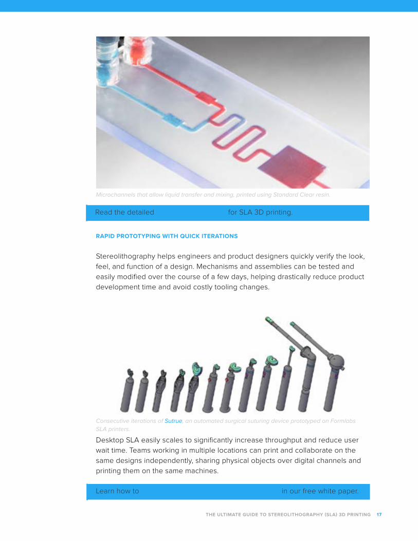
Microchannels that allow liquid transfer and mixing, printed using Standard Clear resin.
Read the detailed design specifications for SLA 3D printing.
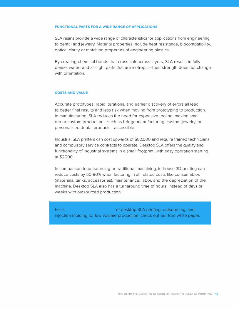
RAPID PROTOTYPING WITH QUICK ITERATIONS
Stereolithography helps engineers and product designers quickly verify the look,
feel, and function of a design. Mechanisms and assemblies can be tested and
easily modified over the course of a few days, helping drastically reduce product
development time and avoid costly tooling changes.
Consecutive iterations of Sutrue, an automated surgical suturing device prototyped on FormlabsSLA printers.
Desktop SLA easily scales to significantly increase throughput and reduce user
wait time. Teams working in multiple locations can print and collaborate on the
same designs independently, sharing physical objects over digital channels and
printing them on the same machines.
Learn how to manage multiple desktop SLA 3D printers in our free white paper.
THE ULTIMATE GUIDE TO STEREOLITHOGRAPHY (SLA) 3D PRINTING 18
FUNCTIONAL PARTS FOR A WIDE RANGE OF APPLICATIONS
SLA resins provide a wide range of characteristics for applications from engineering
to dental and jewelry. Material properties include heat resistance, biocompatibility,
optical clarity or matching properties of engineering plastics.
By creating chemical bonds that cross-link across layers, SLA results in fully
dense, water- and air-tight parts that are isotropic—their strength does not change
with orientation.
COSTS AND VALUE
Accurate prototypes, rapid iterations, and earlier discovery of errors all lead
to better final results and less risk when moving from prototyping to production.
In manufacturing, SLA reduces the need for expensive tooling, making small
run or custom production—such as bridge manufacturing, custom jewelry, or
personalised dental products—accessible.
Industrial SLA printers can cost upwards of $80,000 and require trained technicians
and compulsory service contracts to operate. Desktop SLA offers the quality and
functionality of industrial systems in a small footprint, with easy operation starting
at $2000.
In comparison to outsourcing or traditional machining, in-house 3D printing can
reduce costs by 50-90% when factoring in all related costs like consumables
(materials, tanks, accessories), maintenance, labor, and the depreciation of the
machine. Desktop SLA also has a turnaround time of hours, instead of days or
weeks with outsourced production.
For a cost and time comparison of desktop SLA printing, outsourcing, and
injection molding for low volume production, check out our free white paper.
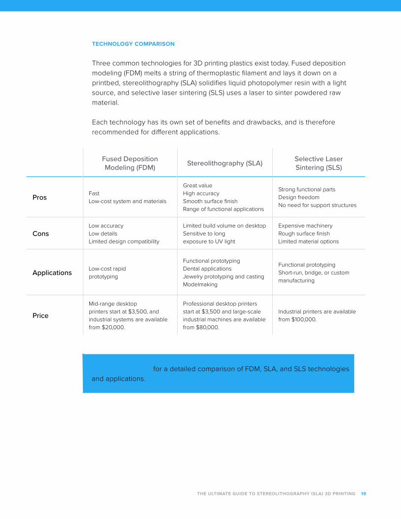
TECHNOLOGY COMPARISON
Three common technologies for 3D printing plastics exist today. Fused deposition
modeling (FDM) melts a string of thermoplastic filament and lays it down on a
printbed, stereolithography (SLA) solidifies liquid photopolymer resin with a light
source, and selective laser sintering (SLS) uses a laser to sinter powdered raw
material.
Each technology has its own set of benefits and drawbacks, and is therefore
recommended for different applications.
THE ULTIMATE GUIDE TO STEREOLITHOGRAPHY (SLA) 3D PRINTING 19
Fused Deposition Modeling (FDM) Stereolithography (SLA) Selective Laser
Sintering (SLS)
Pros Fast
Low-cost system and materials
Great value
High accuracy
Smooth surface finish
Range of functional applications
Strong functional parts
Design freedom
No need for support structures
ConsLow accuracy
Low details
Limited design compatibility
Limited build volume on desktop
Sensitive to long
exposure to UV light
Expensive machinery
Rough surface finish
Limited material options
Applications Low-cost rapid
prototyping
Functional prototyping
Dental applications
Jewelry prototyping and casting
Modelmaking
Functional prototyping
Short-run, bridge, or custom
manufacturing
Price
Mid-range desktop
printers start at $3,500, and
industrial systems are available
from $20,000.
Professional desktop printers
start at $3,500 and large-scale
industrial machines are available
from $80,000.
Industrial printers are available
from $100,000.
Watch our webinar for a detailed comparison of FDM, SLA, and SLS technologies
and applications.
Printing ProcessNow that we understand the theory behind stereolithography, let’s explore what
the printing process looks like on a desktop SLA printer.
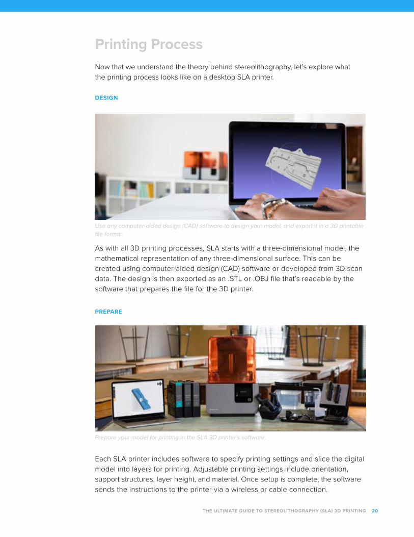
DESIGN
PREPARE
Use any computer-aided design (CAD) software to design your model, and export it in a 3D printable file format.
As with all 3D printing processes, SLA starts with a three-dimensional model, the
mathematical representation of any three-dimensional surface. This can be
created using computer-aided design (CAD) software or developed from 3D scan
data. The design is then exported as an .STL or .OBJ file that’s readable by the
software that prepares the file for the 3D printer.
Each SLA printer includes software to specify printing settings and slice the digital
model into layers for printing. Adjustable printing settings include orientation,
support structures, layer height, and material. Once setup is complete, the software
sends the instructions to the printer via a wireless or cable connection.
Prepare your model for printing in the SLA 3D printer’s software.
THE ULTIMATE GUIDE TO STEREOLITHOGRAPHY (SLA) 3D PRINTING 20
CLEAN
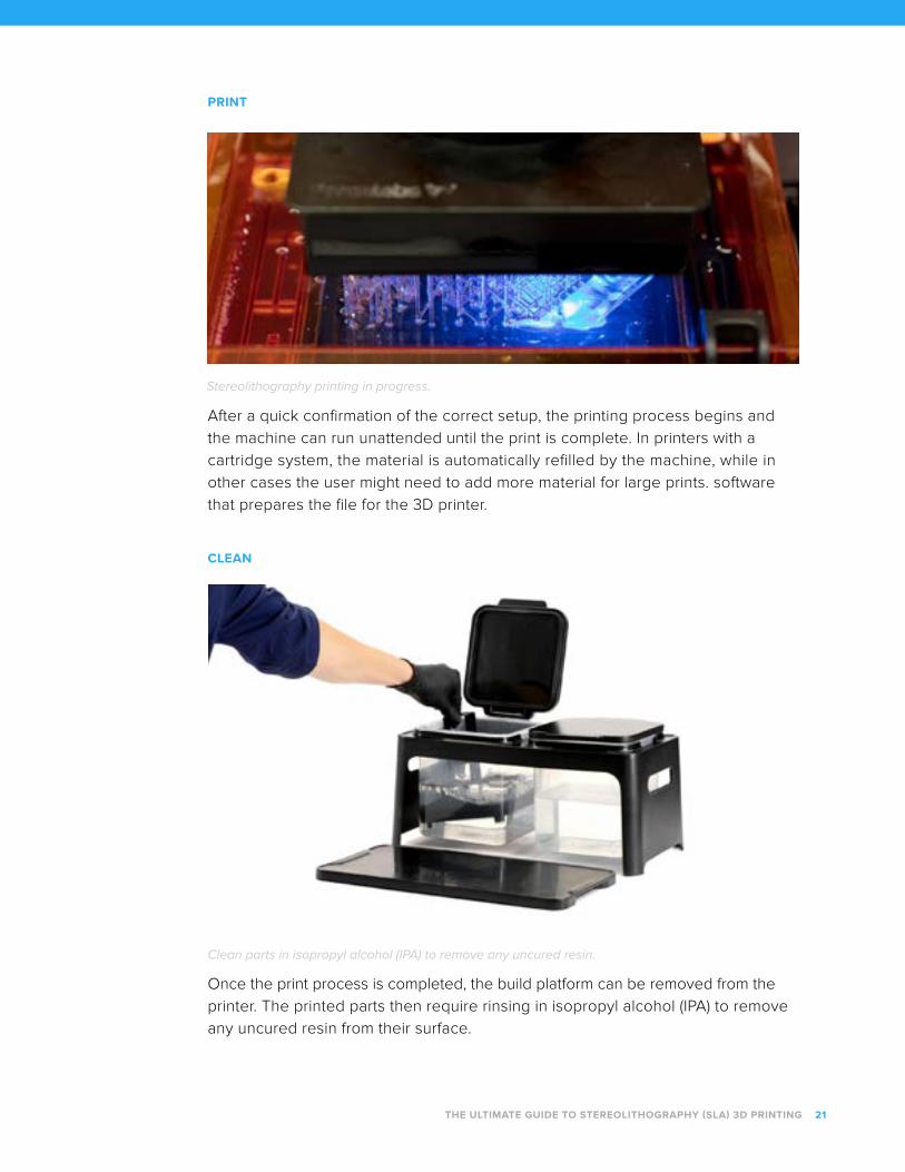
Stereolithography printing in progress.
After a quick confirmation of the correct setup, the printing process begins and
the machine can run unattended until the print is complete. In printers with a
cartridge system, the material is automatically refilled by the machine, while in
other cases the user might need to add more material for large prints. software
that prepares the file for the 3D printer.
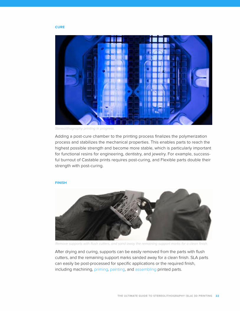
Once the print process is completed, the build platform can be removed from the
printer. The printed parts then require rinsing in isopropyl alcohol (IPA) to remove
any uncured resin from their surface.
Clean parts in isopropyl alcohol (IPA) to remove any uncured resin.
THE ULTIMATE GUIDE TO STEREOLITHOGRAPHY (SLA) 3D PRINTING 21
CURE
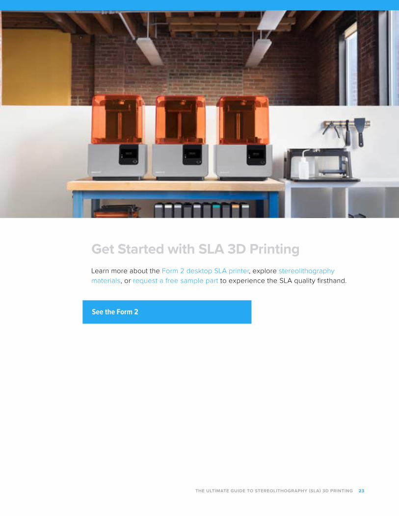
Stereolithography printing in progress.
Adding a post-cure chamber to the printing process finalizes the polymerization
process and stabilizes the mechanical properties. This enables parts to reach the
highest possible strength and become more stable, which is particularly important
for functional resins for engineering, dentistry, and jewelry. For example, success-
ful burnout of Castable prints requires post-curing, and Flexible parts double their
strength with post-curing.
After drying and curing, supports can be easily removed from the parts with flush
cutters, and the remaining support marks sanded away for a clean finish. SLA parts
can easily be post-processed for specific applications or the required finish,
including machining, priming, painting, and assembling printed parts.
Remove supports with flush cutters, and sand away the remaining support marks for a clean finish.
THE ULTIMATE GUIDE TO STEREOLITHOGRAPHY (SLA) 3D PRINTING 22
FINISH
Get Started with SLA 3D PrintingLearn more about the Form 2 desktop SLA printer, explore stereolithography
materials, or request a free sample part to experience the SLA quality firsthand.
THE ULTIMATE GUIDE TO STEREOLITHOGRAPHY (SLA) 3D PRINTING 23
See the Form 2


![A Novel Extrusion-Based Additive Manufacturing Process for ...utw10945.utweb.utexas.edu/sites/default/files/2016/121-Ghazanfari.pdfSintering (SLS) [3], Stereolithography (SLA) [4],](https://img.pdfslide.us/doc/110x75/611e9c7a6f3485277f60f918/a-novel-extrusion-based-additive-manufacturing-process-for-sintering-sls-3.jpg)


![Additive Manufacturing Technologies: 3D printing in Organic … · 1986, [13] the most common being Fused Deposition Modeling (FDM), StereoLithogrAphy (SLA), Selective Laser Sintering](https://img.pdfslide.us/doc/110x75/5f604f5ede94763e98239c03/additive-manufacturing-technologies-3d-printing-in-organic-1986-13-the-most.jpg)


![PTMC: MICROFABRICATION & STEREOLITHOGRAPHY · Stereolithography is a form of prototyping that has been shown to be very versatile with highest accuracy and precision.[11] Stereolithography](https://img.pdfslide.us/doc/110x75/605ef4b2b0307a40e8391640/ptmc-microfabrication-stereolithography-stereolithography-is-a-form-of-prototyping.jpg)