Embed Size (px)
Citation preview
Hang YeDepartment of Industrial and
Systems Engineering,
University at Buffalo,
The State University of New York,
Buffalo, NY 14260
e-mail: [email protected]
Chi Zhou1
Department of Industrial and
Systems Engineering,
University at Buffalo,
The State University of New York,
Buffalo, NY 14260
e-mail: [email protected]
Wenyao XuDepartment of Computer Science
and Engineering,
University at Buffalo,
The State University of New York,
Buffalo, NY 14260
e-mail: [email protected]
Image-Based Slicing and ToolPath Planning for HybridStereolithography AdditiveManufacturingThe hybrid stereolithography (SLA) process integrates a laser scanning-based systemand a mask projection-based system. Multiple laser paths are used to scan the border ofa 2D pattern, whereas a mask image is adopted to solidify the interior area. By integrat-ing merits of two subsystems, the hybrid SLA process can achieve high surface qualitywithout sacrificing productivity. For the hybrid system, closed polygonal contours arerequired to direct the laser scanning, and a binary image is also needed for the mask pro-jection. We proposed a novel image-based slicing method. This approach can convert a3D model into a series of binary images directly, and each image is corresponding to thecross section of the model at a specific height. Based on the resultant binary image, weuse an image processing method to gradually shrink the pattern in the image. Boundariesof the shrunk image are traced and then restored as polygons to direct the laser spotmovement. The final shrunk image serves as the input for the mask projection. Experi-mental results of test cases demonstrate that the proposed method is substantially moreefficient than the traditional approaches. Its accuracy is also studied and discussed.[DOI: 10.1115/1.4035795]
Keywords: additive manufacturing, stereolithography, slicing, contour tracing, imageshrinking
1 Introduction
Among various additive manufacturing (AM) processes, thestereolithography apparatus (SLA) was the first commercializedone [1], and it is one of the most popular AM technologies nowa-days. There are two typical SLA configurations [1]. One is to usea laser to cure the liquid resin, and the laser scans the cross-sectional area point by point. An advantage of this configurationis that it can generate comparatively high accuracy, but it is time-consuming as the laser spot has to pass all points within the crosssection. The other configuration is the application of projectiondevices, such as a digital light projection (DLP), to illuminate theliquid resin. It can dramatically reduce the production timebecause the whole layer is cured simultaneously by exposing adesigned digital mask. But its accuracy is limited by the resolutionof the projection device. Extensive research work has been doneto improve the efficiency and/or accuracy of SLA from differentperspectives [2–7,28].
However, most researchers in this field have been focusing onimproving either one of the two configurations, and it wouldalways result in making trade-off between efficiency and accu-racy. This inherent trade-off has been identified as a major tech-nology barrier existing across many AM processes [8]. Mostrecently, Zhou et al. proposed a hybrid SLA process to combinethe laser scanning with the projection such that one subsystem cancomplement the other to improve the overall performance [9]. Itadopts a laser as the energy source for the border of a 2D pattern,whereas a mask image is used to solidify the interior area.Because a single laser path results in ultrathin lines, multiple pathsare necessary on the border area to offer sufficient mechanicalstrength and to securely bond the material on the boundary withthe internal body [9]. The hybrid SLA system can take advantages
from both sides, i.e., achieving relatively high surface qualitywithout sacrificing productivity.
Although traditional slicing and tool path planning approachescan be applied to the hybrid SLA system seamlessly, aconfiguration-specific method is desirable. In this paper, we willintroduce a novel slicing and tool path planning method whichcan well suit the hybrid system. The remainder of this paper isorganized as follows: Section 2 will review how the existing slic-ing and tool path planning approaches can be adopted by thehybrid system, and a new data flow paradigm will be proposed.Section 3 will introduce an image-based slicing method which canconvert an STL format 3D model into binary images directly. Thesampling accuracy will also be discussed in this section. Section 4will describe an image contraction method to shrink the originalbinary image, and the resulting error will be investigated as well.The efficiency analysis and experimental results will be presentedin Sec. 5. The conclusion will be discussed in Sec. 6.
2 Data Flow for Hybrid Stereolithography System
2.1 Flow Chart of Slicing and Tool Path Planning. Thehybrid system synthesizes a laser scanning-based SLA system anda mask projection-based SLA system. Therefore, input files fromboth sides are required for this system. To be specific, at eachlayer two input files are necessary: (1) contours for laser scanningand (2) a binary image for mask projection. We will review howto use the traditional method to generate these two required inputdata in this section.
The AM process usually takes an stereolithography (STL) fileas the raw data, which is the triangulated surface representation ofa 3D object. To build an object in a layer by layer fashion, theshape of the cross section at each layer is required. The process toobtain the geometric property of the cross section area for eachlayer is usually termed as “slicing.” A common practice for slicingis to calculate the intersections between a given slicing plane and
1Corresponding author.Manuscript received September 21, 2016; final manuscript received December
21, 2016; published online March 8, 2017. Assoc. Editor: Zhijian J. Pei.
Journal of Manufacturing Science and Engineering JULY 2017, Vol. 139 / 071006-1Copyright VC 2017 by ASME
Downloaded From: http://manufacturingscience.asmedigitalcollection.asme.org/pdfaccess.ashx?url=/data/journals/jmsefk/936106/ on 07/15/2017 Terms of Use: http://www.asme.org/about-asme/terms-of-use
triangular meshes from the STL file, and then all intersections arere-organized to obtain a contour (simple polygon). For the laserscanning-based SLA process, a series of polygons are generatedafter slicing by offsetting, and the offset distance t is always nega-tive, i.e., inward offsetting for outside contour and outward offset-ting for inside contour. These offset polygons serve as paths forlaser scanning in the hybrid system. For the mask projection-based SLA process, the input is a series of binary (or gray scale)images. The pattern in each image is defined by the area enclosedby a contour (or by nested outside and inside contours). The majorsteps to convert a contour into a binary image include: (1) select asampling point for each pixel from the area the pixel covered; (2)test whether the selected point is in the area encompassed by thecontour; (3) if the sampling point is in the area, set its correspond-ing pixel as a foreground pixel. Otherwise, its corresponding pixelwill be set as background. The scanline rendering algorithm [10]which implements this idea is the common practice to convertcontour information into a binary image. In the hybrid system, thearea for the mask projection is defined by the innermost polygongenerated from the outside contour and the outermost polygongenerated from the inside contour. The liquid photopolymer atother areas on the cross section will be cured by the laserscanning.
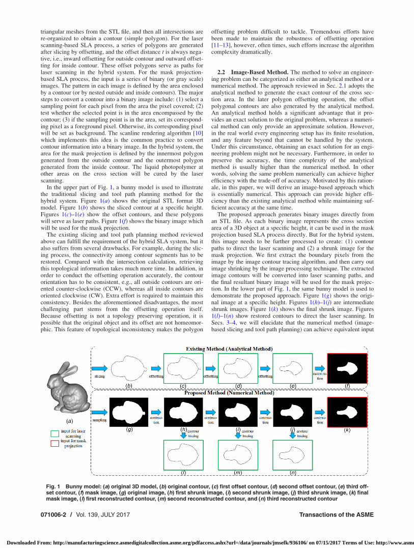
In the upper part of Fig. 1, a bunny model is used to illustratethe traditional slicing and tool path planning method for thehybrid system. Figure 1(a) shows the original STL format 3Dmodel. Figure 1(b) shows the sliced contour at a specific height.Figures 1(c)–1(e) show the offset contours, and these polygonswill serve as laser paths. Figure 1(f) shows the binary image whichwill be used for the mask projection.
The existing slicing and tool path planning method reviewedabove can fulfill the requirement of the hybrid SLA system, but italso suffers from several drawbacks. For example, during the slic-ing process, the connectivity among contour segments has to berestored. Compared with the intersection calculation, retrievingthis topological information takes much more time. In addition, inorder to conduct the offsetting operation accurately, the contourorientation has to be consistent, e.g., all outside contours are ori-ented counter-clockwise (CCW), whereas all inside contours areoriented clockwise (CW). Extra effort is required to maintain thisconsistency. Besides the aforementioned disadvantages, the mostchallenging part stems from the offsetting operation itself.Because offsetting is not a topology preserving operation, it ispossible that the original object and its offset are not homeomor-phic. This feature of topological inconsistency makes the polygon
offsetting problem difficult to tackle. Tremendous efforts havebeen made to maintain the robustness of offsetting operation[11–13], however, often times, such efforts increase the algorithmcomplexity dramatically.
2.2 Image-Based Method. The method to solve an engineer-ing problem can be categorized as either an analytical method or anumerical method. The approach reviewed in Sec. 2.1 adopts theanalytical method to generate the exact contour of the cross sec-tion area. In the later polygon offsetting operation, the offsetpolygonal contours are also generated by the analytical method.An analytical method holds a significant advantage that it pro-vides an exact solution to the original problem, whereas a numeri-cal method can only provide an approximate solution. However,in the real world every engineering setup has its finite resolution,and any feature beyond that cannot be handled by the system.Under this circumstance, obtaining an exact solution for an engi-neering problem might not be necessary. Furthermore, in order topreserve the accuracy, the time complexity of the analyticalmethod is usually higher than the numerical method. In otherwords, solving the same problem numerically can achieve higherefficiency with the trade-off of accuracy. Motivated by this ration-ale, in this paper, we will derive an image-based approach whichis essentially numerical. This approach can provide higher effi-ciency than the existing analytical method while maintaining suf-ficient accuracy at the same time.
The proposed approach generates binary images directly froman STL file. As each binary image represents the cross sectionarea of a 3D object at a specific height, it can be used in the maskprojection based SLA process directly. But for the hybrid system,this image needs to be further processed to create: (1) contourpaths to direct the laser scanning and (2) a shrunk image for themask projection. We first extract the boundary pixels from theimage by the image contour tracing algorithm, and then carry outimage shrinking by the image processing technique. The extractedimage contours will be converted into laser scanning paths, andthe final resultant binary image will be used for the mask projec-tion. In the lower part of Fig. 1, the same bunny model is used todemonstrate the proposed approach. Figure 1(g) shows the origi-nal image at a specific height. Figures 1(h)–1(j) are intermediateshrunk images. Figure 1(k) shows the final shrunk image. Figures1(l)–1(n) show restored contours to direct the laser scanning. InSecs. 3–4, we will elucidate that the numerical method (image-based slicing and tool path planning) can achieve equivalent input
Fig. 1 Bunny model: (a) original 3D model, (b) original contour, (c) first offset contour, (d) second offset contour, (e) third off-set contour, (f) mask image, (g) original image, (h) first shrunk image, (i) second shrunk image, (j) third shrunk image, (k) finalmask image, (l) first reconstructed contour, (m) second reconstructed contour, and (n) third reconstructed contour
071006-2 / Vol. 139, JULY 2017 Transactions of the ASME
Downloaded From: http://manufacturingscience.asmedigitalcollection.asme.org/pdfaccess.ashx?url=/data/journals/jmsefk/936106/ on 07/15/2017 Terms of Use: http://www.asme.org/about-asme/terms-of-use
data for the printing process with substantially higher efficiencythan the analytical method.
3 Image-Based Slicing Algorithm
3.1 Existing Slicing Approach. Most existing slicing meth-ods fall into one of the two categories: nontopology-based andtopology-based. For both methods, it is necessary to compute theintersection between a given line segment (defined by two verticesV1(X1, Y1, Z1) and V2(X2, Y2, Z2)) and a horizontal plane (Z¼ Zk),and it can be easily calculated by linear interpolation [9].
For the nontopology-based method, each triangular facet froman STL model needs to be traversed to check whether it intersectswith the current slicing plane or not. If n triangles intersect withcurrent slicing plane, 2n end points from n line segments will becomputed, and their connectivity can be determined by the“closest point” method [1,29]. The topology-based method is alsoknown as “marching” algorithm. The key of this method is thehalf-edge data structure (also referred as “doubly-connected edgelist” in Ref. [14]). All edges from an STL model need to be pre-processed to make mesh connectivity explicit. With this informa-tion, we can march from one triangle to the next until getting backto the starting triangle which closes the polygonal contour [15].
The nontopology-based method is straightforward, but orderingline segments is time-consuming. Although the time complexityof the topology-based method is lower than the nontopology-based method, a sophisticated data structure has to be created, andthe construction of this data structure can also be time-consuming.In addition, this method is not as robust as the nontopology-basedmethod. The idea of “information reuse” introduced in Refs. [16]and [17] aims to improve the slicing efficiency from another per-spective. It takes advantage of known information obtained from atemplate model to accelerate the slicing of its derivatives.Although this method is very efficient for derived models, thetemplate model still has to be sliced by either the topology-basedor the nontopology-based method.
3.2 Image-Based Slicing Method. In this section, an image-based method is presented. It generates a binary image with afinite resolution, denoted as cA, to represent a 2D planar area Adirectly from an STL file. Major steps of the image-based slicingalgorithm include: (1) convert the STL file into the sampling pointcloud and (2) generate a series of images according to samplingpoints from bottom to top in an accumulative manner.
3.2.1 Sampling Point Conversion. For a solid S in R3, itsSTL file can be seen as a triangulated surface representation of S.In the context of geometric modeling, a surface is defined as “anorientable continuous 2D manifold embedded in R3 [18], denotedas @S. Here, @S is an infinite set whose elements are orientablepoints. Sampling points are some points we intentionally selectfrom @S in order to approximately represent the surface. In otherwords, the set of sampling points I is a proper subset of @S.
Suppose the binary image to be generated is positioned at a rec-tangular area defined by its four vertices (0, 0, 0), (W, 0, 0), (W,H, 0), and (0, H, 0), and a 3D model is also placed in this planardomain. If the resolution of the image is m� n, the area each pixelcovered is a grid with the width d¼W/m (or H/n). Among all ele-ments in @S, the points with the following X- and Y-coordinatesare selected as sampling points. The Z-coordinate for a samplingpoint can be obtained by calculating the intersection between theline represented by Eq. (1) and the triangular facet defined by itsthree vertices
Xij ¼ ði� 0:5Þd; for i ¼ 1; 2;…mYij ¼ ðj� 0:5Þd; for j ¼ 1; 2;…n
�(1)
The pseudocode for converting an STL file into sampling points isshown as below. Algorithm SCANLINERENDERING (T[i], d) is the
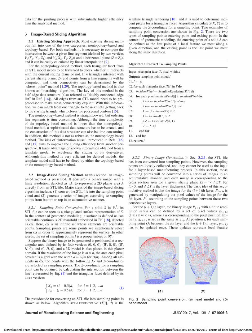
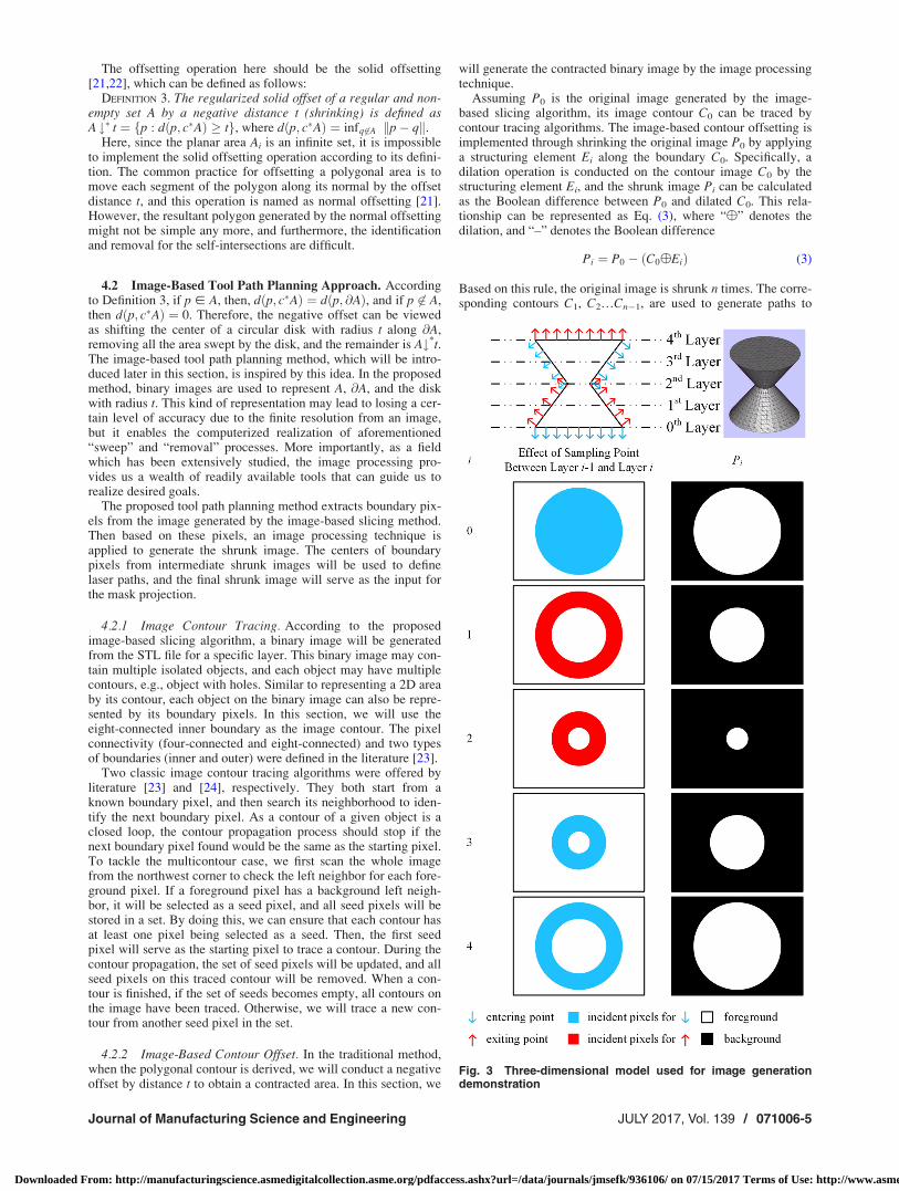
scanline triangle rendering [10], and it is used to determine inci-dent pixels for a triangular facet. Algorithm calculate Z(X, Y) is tocompute the Z-coordinate for a sampling point. Two examples ofsampling point conversion are shown in Fig. 2. There are twotypes of sampling points: entering point and exiting point. In thecontext of geometric modeling, the entering point of a solid S canbe defined as the first point of a local feature we meet along agiven direction, and the exiting point is the last point we meetalong the same direction.
Algorithm 1 Convert To Sampling Points
Input: triangular facet T, pixel width d
Output: sampling point cloud I
01. I /
02. for each triangular facet T[i] in T do
03. incidentPixel ScanlineRendering(T[i], d)
04. for each pixel incidentPixel[j] in incidentPixel do
05. S.col incidentPixel[j].column
06. S.row incidentPixel[j].row
07. X (S.column-0.5)� d
08. Y (S.row-0.5)� d
09. S.Z Calculate Z(X, Y)
10. I I [ S
11. end for
12. end for
13. return I
3.2.2 Binary Image Generation. In Sec. 3.2.1, the STL filehas been converted into sampling points. However, the samplingpoints are loosely collected, and they cannot be used as the inputfor a layer-based manufacturing process. In this section, thosesampling points will be converted into a series of images in anaccumulative manner, and each image is corresponding to thecross section area for a given slicing plane (Z¼ i� d_LT, fori> 0, and d_LT is the layer thickness). The basic idea of this accu-mulative method is that the image for the (iþ 1)th layer, Piþ 1, isgenerated by manipulating the pixel values of the image for theith layer, Pi, according to the sampling points between these twoconsecutive layers.
For the (iþ 1)th layer, the binary image Piþ 1 with a finite reso-lution m� n can be defined by a set of pixel values giþ 1,j
(1� j�m� n), where j is corresponding to the pixel position. Ini-tially, giþ 1,j is set as the same as gi,j. At position j, for each sam-pling point Qk between the ith layer and the (iþ 1)th layer, giþ 1,j
has to be updated once. These updates represent local feature
Fig. 2 Sampling point conversion: (a) head model and (b)hand model
Journal of Manufacturing Science and Engineering JULY 2017, Vol. 139 / 071006-3
Downloaded From: http://manufacturingscience.asmedigitalcollection.asme.org/pdfaccess.ashx?url=/data/journals/jmsefk/936106/ on 07/15/2017 Terms of Use: http://www.asme.org/about-asme/terms-of-use
changes along the building direction. For a closed 2D manifold,the entering point and the exiting point must occur one after theother, and at each pixel position the total number ofsampling points must be even. Therefore, the relation between gi,j
and giþ 1, j can be summarized as in the following equation:
giþ1;j ¼gi;j if # of Qk is even
ðgi;j þ 1Þ mod 2 if # of Qk is odd
�(2)
The pseudocode for the binary image generation is shown asbelow. The image is generated from the bottom to the top, andeach sampling point only takes effect once. Therefore, sorting allsampling points according to their Z-coordinates can make thisalgorithm more efficient, and only the sampling points that fallbetween two consecutive layers need to be visited to generate animage corresponding to a specific height. In Fig. 3, an exampleobject is used to demonstrate how binary images are generatedfrom sampling points. Initially, all pixels in the image are set asbackground. At the zeroth layer, since all sampling points areentering points, all pixels in the circular area are set as foreground.At the first layer, all sampling points between the zeroth and thefirst layers are exiting points. Therefore, based on P0, all pixels inthe annulus are set as background. Following the same rule, wecan derive P2, P3, and P4.
3.3 Sampling Accuracy. Because the proposed image-basedslicing algorithm selects a finite number of points from @S as sam-pling points, some features of @S might be missing. However, it isnecessary to guarantee the topological equivalence between anoriginal 3D object S and the reconstruction of its digital images.In other words, S and its reconstruction have to be homeomorphic.The importance of homeomorphism has been briefly discussed inRef. [19,27]. Intuitively, the denser a sampling point cloud is, themore possible a 3D object S and its reconstruction is homeomor-phic. But if the sampling point cloud is too dense, its generationand processing will be extremely time-consuming. In addition, aseach projector has its own finite resolution, it will be pointless touse higher resolution images. In this section, we will briefly dis-cuss the sufficient condition to ensure the homeomorphismbetween S and its reconstruction.
The following definitions and theorem are adopted from Ref.[20], and Definition 1 and Theorem 1 are Definition 1 and Theo-rem 16 in Ref. [20], respectively.
DEFINITION 1. A set S � R3 is called r-regular if, for each pointx � @S, there exist two osculating open balls of radius r to @S at xsuch that one lies entirely in S and the other lies entirely in thecomplementary set of S.
DEFINITION 2. Any set G which is a translated and rotatedversion of the set ð2r0=
ffiffiffi3pÞZ3 is called a cubic r0-grid,and its ele-
ments are called grid points.THEOREM 1. Let S be an r-regular object and G be a cubic r0-
grid with 2r0< r. Then, the result of a topology preserving recon-struction method is r-homeomorphic to S.
From Definition 2, the edge length of a cubicr0� grid d0 ¼ 2r0=
ffiffiffi3p
. According to Theorem 1, we can derive thefollowing conclusion: For an r-regular object S and a cubic r0-gridG, if the edge length of G, d0, satisfies d0 < ð
ffiffiffi3p
=3Þ r, the result ofa topology preserving reconstruction method is r-homeomorphicto S.
In the context of additive manufacturing, in the X–Y plane, d0 isrepresented by the pixel width d. And in building direction(Z-axis), d0 is represented by the layer thickness d_LT. Therefore,we can conclude that for an r-regular object S, if both the pixelwidth d and the layer thickness d_LT are less than ð
ffiffiffi3p
=3Þ r, thehomeomorphism between S and its reconstruction can beguaranteed.
It is not necessary that all 3D models are r-regular. Forinstance, a polyhedron does not fall in this category. However, forthe model to be built by an AM process, the magnitude of the
parameter r can be interpreted as the size of the minimal spatialfeature of the model. This is because any AM setup has a finiteresolution, and objects fabricated by this specific machine canonly present features whose sizes are larger than this defined reso-lution. This resolution is comprised of two independent compo-nents, the lateral resolution (X- and Y-axis direction) and thevertical resolution (Z-axis direction). For an SLA process, the lat-eral resolution is defined by the diameter of a laser spot (for thelaser scanning-based SLA process) or the physical size of a pixel(for the mask projection-based SLA process). The vertical resolu-tion is defined by the minimal step length of the elevator and thepenetration depth of the resin. If the minimal feature from anobject is beyond these thresholds, it cannot be built as desired.Therefore, in order to properly build an object with minimal spa-tial feature size r, both the pixel size and the layer thickness haveto be less than ð
ffiffiffi3p
=3Þ r.
Algorithm 2 Binary Image Generation
Input: sampling point cloud I, layer thickness d_LT
Output: binary image set P
01. P /
02. I0 Sort I according to Z-coordinate
03. for j 1 to m� n do
04. g[j] 0
05. num[j] 0
06. end for
07. i 1
08. k 1
09. size size of I0
10. while k� size do
11. if I0[k].Z� I0[1].Zþ i� d_LT then
12. j (I0[k].row-1) �nþ I0[k].column
13. num[j] num[j]þ 1
14. k kþ 1
15. else
16. for j 1 to m� n do
17. if num[j] mod 2¼ 1 then
18. g[j] (g[j]þ1) mod 2
19. end if
20. P½i� P½i� [ g½j�21. num[j] 0
22. end for
23. P P [ P½i�24. i iþ 1
25. end if
26. end while
27. return P
4 Image-Based Tool Path Planning
4.1 Existing Tool Path Planning Method. As shown in theupper part of Fig. 1, the existing tool path planning for the hybridSLA process takes the polygonal contour (Fig. 1(b)) as input, andthis contour information is obtained from slicing. Each polygonalcontour L0 encloses an area A0, and successively negative offset-ting (shrinkage) will be conducted on this area with the offset dis-tance ti. Consequently, a series of shrunk areas Ai for i¼ 1, 2,3…n will be generated, and their corresponding polygonal con-tours Li for i¼ 1, 2, 3…n� 1 will serve as laser paths. The areaenclosed by the last polygonal contour, An, will be converted intoa binary image to serve as the input for the mask projection.
071006-4 / Vol. 139, JULY 2017 Transactions of the ASME
Downloaded From: http://manufacturingscience.asmedigitalcollection.asme.org/pdfaccess.ashx?url=/data/journals/jmsefk/936106/ on 07/15/2017 Terms of Use: http://www.asme.org/about-asme/terms-of-use
The offsetting operation here should be the solid offsetting[21,22], which can be defined as follows:
DEFINITION 3. The regularized solid offset of a regular and non-empty set A by a negative distance t (shrinking) is defined asA #� t ¼ fp : dðp; c�AÞ � tg, where dðp; c�AÞ ¼ infq 62A kp� qk.
Here, since the planar area Ai is an infinite set, it is impossibleto implement the solid offsetting operation according to its defini-tion. The common practice for offsetting a polygonal area is tomove each segment of the polygon along its normal by the offsetdistance t, and this operation is named as normal offsetting [21].However, the resultant polygon generated by the normal offsettingmight not be simple any more, and furthermore, the identificationand removal for the self-intersections are difficult.
4.2 Image-Based Tool Path Planning Approach. Accordingto Definition 3, if p � A, then, dðp; c�AÞ ¼ dðp; @AÞ, and if p 62 A,then dðp; c�AÞ ¼ 0. Therefore, the negative offset can be viewedas shifting the center of a circular disk with radius t along @A,removing all the area swept by the disk, and the remainder is A#*t.The image-based tool path planning method, which will be intro-duced later in this section, is inspired by this idea. In the proposedmethod, binary images are used to represent A, @A, and the diskwith radius t. This kind of representation may lead to losing a cer-tain level of accuracy due to the finite resolution from an image,but it enables the computerized realization of aforementioned“sweep” and “removal” processes. More importantly, as a fieldwhich has been extensively studied, the image processing pro-vides us a wealth of readily available tools that can guide us torealize desired goals.
The proposed tool path planning method extracts boundary pix-els from the image generated by the image-based slicing method.Then based on these pixels, an image processing technique isapplied to generate the shrunk image. The centers of boundarypixels from intermediate shrunk images will be used to definelaser paths, and the final shrunk image will serve as the input forthe mask projection.
4.2.1 Image Contour Tracing. According to the proposedimage-based slicing algorithm, a binary image will be generatedfrom the STL file for a specific layer. This binary image may con-tain multiple isolated objects, and each object may have multiplecontours, e.g., object with holes. Similar to representing a 2D areaby its contour, each object on the binary image can also be repre-sented by its boundary pixels. In this section, we will use theeight-connected inner boundary as the image contour. The pixelconnectivity (four-connected and eight-connected) and two typesof boundaries (inner and outer) were defined in the literature [23].
Two classic image contour tracing algorithms were offered byliterature [23] and [24], respectively. They both start from aknown boundary pixel, and then search its neighborhood to iden-tify the next boundary pixel. As a contour of a given object is aclosed loop, the contour propagation process should stop if thenext boundary pixel found would be the same as the starting pixel.To tackle the multicontour case, we first scan the whole imagefrom the northwest corner to check the left neighbor for each fore-ground pixel. If a foreground pixel has a background left neigh-bor, it will be selected as a seed pixel, and all seed pixels will bestored in a set. By doing this, we can ensure that each contour hasat least one pixel being selected as a seed. Then, the first seedpixel will serve as the starting pixel to trace a contour. During thecontour propagation, the set of seed pixels will be updated, and allseed pixels on this traced contour will be removed. When a con-tour is finished, if the set of seeds becomes empty, all contours onthe image have been traced. Otherwise, we will trace a new con-tour from another seed pixel in the set.
4.2.2 Image-Based Contour Offset. In the traditional method,when the polygonal contour is derived, we will conduct a negativeoffset by distance t to obtain a contracted area. In this section, we
will generate the contracted binary image by the image processingtechnique.
Assuming P0 is the original image generated by the image-based slicing algorithm, its image contour C0 can be traced bycontour tracing algorithms. The image-based contour offsetting isimplemented through shrinking the original image P0 by applyinga structuring element Ei along the boundary C0. Specifically, adilation operation is conducted on the contour image C0 by thestructuring element Ei, and the shrunk image Pi can be calculatedas the Boolean difference between P0 and dilated C0. This rela-tionship can be represented as Eq. (3), where “�” denotes thedilation, and “–” denotes the Boolean difference
Pi ¼ P0 � ðC0�EiÞ (3)
Based on this rule, the original image is shrunk n times. The corre-sponding contours C1, C2…Cn�1, are used to generate paths to
Fig. 3 Three-dimensional model used for image generationdemonstration
Journal of Manufacturing Science and Engineering JULY 2017, Vol. 139 / 071006-5
Downloaded From: http://manufacturingscience.asmedigitalcollection.asme.org/pdfaccess.ashx?url=/data/journals/jmsefk/936106/ on 07/15/2017 Terms of Use: http://www.asme.org/about-asme/terms-of-use
direct the laser scanning, and the final shrunk image Pn serves asthe input for the mask projection.
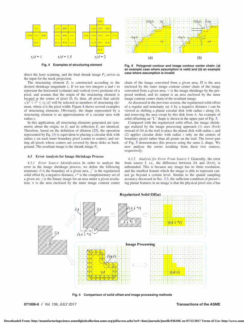
The structuring element Ei is constructed according to thedesired shrinkage magnitude ti. If we use two integers u and v torepresent the horizontal (column) and vertical (row) positions of apixel, and assume that the origin of the structuring element islocated at the center of pixel (0, 0), then, all pixels that satisfyffiffiffiffiffiffiffiffiffiffiffiffiffiffiffi
u2 þ v2p
� ðti=dÞ will be selected as members of structuring ele-ment, where d is the pixel width. Figure 4 shows several examplesof structuring elements. Obviously, the shape represented by astructuring element is an approximation of a circular area withradius ti.
In this application, all structuring elements generated are sym-metric about the origin, so Ei and its reflection Ei are identical.Therefore, based on the definition of dilation [25], the operationrepresented by Eq. (3) is equivalent to placing a circular disk withradius ti on each inner boundary pixel (center to center), and set-ting all pixels whose centers are covered by these disks as back-ground. The resultant image is the shrunk image Pi.
4.3 Error Analysis for Image Shrinkage Process
4.3.1 Error Source Identification. In order to analyze theerror in the image shrinkage process, we define the followingnotations: @ is the boundary of a given area, #* is the regularizedsolid offset by a negative distance, c* is the complementary set ofa given set, c is the binary image for an area under a given resolu-tion, p is the area enclosed by the inner image contour center
chain of the image converted from a given area, P is the areaenclosed by the outer image contour center chain of the imageconverted from a given area, � is the image shrinkage by the pro-posed method, and its output is an area enclosed by the innerimage contour center chain of the resultant image.
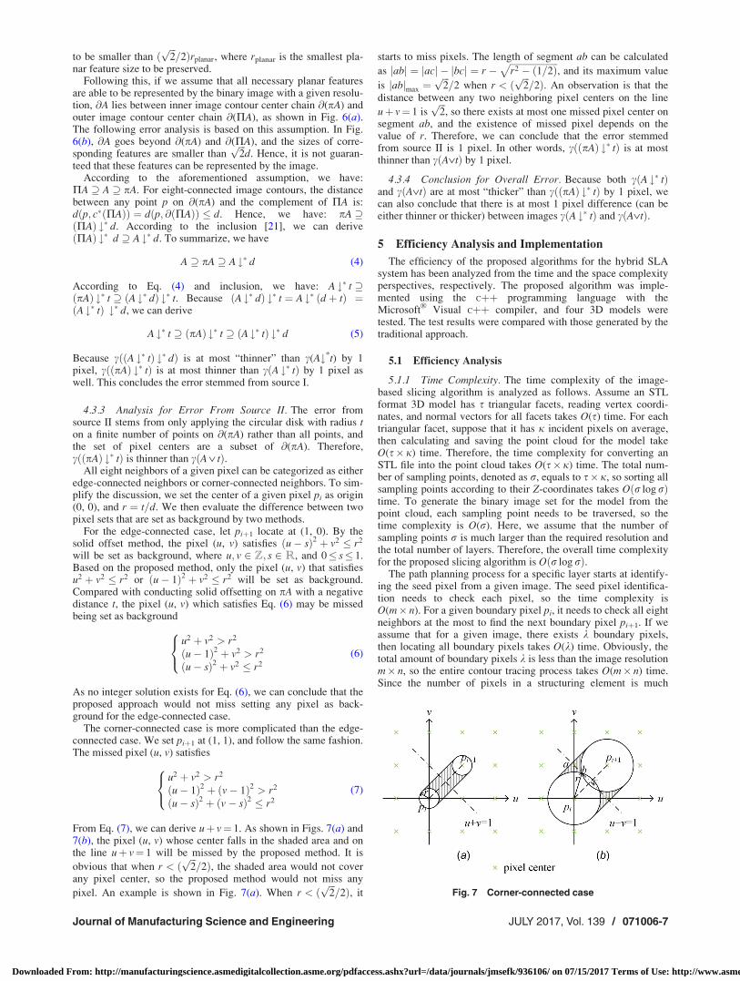
As discussed in the previous session, the regularized solid offsetof a regular and nonempty set A by a negative distance t can beviewed as shifting a planar circular disk with radius t along @A,and removing the area swept by this disk from A. An example ofsolid offsetting an “L” shape is shown in the upper part of Fig. 5.
Compared with the regularized solid offset, the image shrink-age realized by the image processing approach (1) uses @(pA)instead of @A as the trail to place the planar disk with radius t, and(2) applies circular disks with radius t only on the centers ofboundary pixels rather than all points on the trail. The lower partof Fig. 5 demonstrates this process using the same L shape. Wenow analyze the errors resulting from these two sources,respectively.
4.3.2 Analysis for Error From Source I. Generally, the errorfrom source I, i.e., the difference between @A and @(pA), isunbounded. This is because any image has its finite resolution,and the smallest feature which the image is able to represent can-not go beyond a certain level. Similar to the spatial samplingaccuracy discussed in Sec. 3.3, the sufficient condition of preserv-ing planar features in an image is that the physical pixel size d has
Fig. 4 Examples of structuring element
Fig. 5 Comparison of solid offset and image processing methods
Fig. 6 Polygonal contour and image contour center chain: (a)an example case where assumption is valid and (b) an examplecase where assumption is invalid
071006-6 / Vol. 139, JULY 2017 Transactions of the ASME
Downloaded From: http://manufacturingscience.asmedigitalcollection.asme.org/pdfaccess.ashx?url=/data/journals/jmsefk/936106/ on 07/15/2017 Terms of Use: http://www.asme.org/about-asme/terms-of-use
to be smaller than ðffiffiffi2p
=2Þrplanar, where rplanar is the smallest pla-nar feature size to be preserved.
Following this, if we assume that all necessary planar featuresare able to be represented by the binary image with a given resolu-tion, @A lies between inner image contour center chain @(pA) andouter image contour center chain @(PA), as shown in Fig. 6(a).The following error analysis is based on this assumption. In Fig.6(b), @A goes beyond @(pA) and @(PA), and the sizes of corre-sponding features are smaller than
ffiffiffi2p
d. Hence, it is not guaran-teed that these features can be represented by the image.
According to the aforementioned assumption, we have:PA A pA. For eight-connected image contours, the distancebetween any point p on @(pA) and the complement of PA is:dðp; c�ðPAÞÞ ¼ dðp; @ðPAÞÞ � d. Hence, we have: pA ðPAÞ #� d. According to the inclusion [21], we can deriveðPAÞ #� d A #� d. To summarize, we have
A pA A #� d (4)
According to Eq. (4) and inclusion, we have: A #� t ðpAÞ #� t ðA #� dÞ #� t. Because ðA #� dÞ #� t ¼ A #� ðd þ tÞ ¼ðA #� tÞ #� d, we can derive
A #� t ðpAÞ #� t ðA #� tÞ #� d (5)
Because cððA #� tÞ #� dÞ is at most “thinner” than c(A#*t) by 1pixel, cððpAÞ #� tÞ is at most thinner than cðA #� tÞ by 1 pixel aswell. This concludes the error stemmed from source I.
4.3.3 Analysis for Error From Source II. The error fromsource II stems from only applying the circular disk with radius ton a finite number of points on @(pA) rather than all points, andthe set of pixel centers are a subset of @(pA). Therefore,cððpAÞ #� tÞ is thinner than cðA � tÞ.
All eight neighbors of a given pixel can be categorized as eitheredge-connected neighbors or corner-connected neighbors. To sim-plify the discussion, we set the center of a given pixel pi as origin(0, 0), and r ¼ t=d. We then evaluate the difference between twopixel sets that are set as background by two methods.
For the edge-connected case, let piþ1 locate at (1, 0). By thesolid offset method, the pixel (u, v) satisfies ðu� sÞ2 þ v2 � r2
will be set as background, where u; v 2 Z; s 2 R, and 0� s� 1.Based on the proposed method, only the pixel (u, v) that satisfiesu2 þ v2 � r2 or ðu� 1Þ2 þ v2 � r2 will be set as background.Compared with conducting solid offsetting on pA with a negativedistance t, the pixel (u, v) which satisfies Eq. (6) may be missedbeing set as background
u2 þ v2 > r2
ðu� 1Þ2 þ v2 > r2
ðu� sÞ2 þ v2 � r2
8<: (6)
As no integer solution exists for Eq. (6), we can conclude that theproposed approach would not miss setting any pixel as back-ground for the edge-connected case.
The corner-connected case is more complicated than the edge-connected case. We set piþ1 at (1, 1), and follow the same fashion.The missed pixel (u, v) satisfies
u2 þ v2 > r2
ðu� 1Þ2 þ ðv� 1Þ2 > r2
ðu� sÞ2 þ ðv� sÞ2 � r2
8<: (7)
From Eq. (7), we can derive uþ v¼ 1. As shown in Figs. 7(a) and7(b), the pixel (u, v) whose center falls in the shaded area and onthe line uþ v¼ 1 will be missed by the proposed method. It is
obvious that when r < ðffiffiffi2p
=2Þ, the shaded area would not coverany pixel center, so the proposed method would not miss any
pixel. An example is shown in Fig. 7(a). When r < ðffiffiffi2p
=2Þ, it
starts to miss pixels. The length of segment ab can be calculated
as jabj ¼ jacj � jbcj ¼ r �ffiffiffiffiffiffiffiffiffiffiffiffiffiffiffiffiffiffiffiffiffir2 � ð1=2Þ
p, and its maximum value
is jabjmax ¼ffiffiffi2p
=2 when r < ðffiffiffi2p
=2Þ. An observation is that thedistance between any two neighboring pixel centers on the line
uþ v¼ 1 isffiffiffi2p
, so there exists at most one missed pixel center onsegment ab, and the existence of missed pixel depends on thevalue of r. Therefore, we can conclude that the error stemmedfrom source II is 1 pixel. In other words, cððpAÞ #� tÞ is at mostthinner than cðA�tÞ by 1 pixel.
4.3.4 Conclusion for Overall Error. Because both cðA #� tÞand cðA�tÞ are at most “thicker” than cððpAÞ #� tÞ by 1 pixel, wecan also conclude that there is at most 1 pixel difference (can beeither thinner or thicker) between images cðA #� tÞ and cðA�tÞ.
5 Efficiency Analysis and Implementation
The efficiency of the proposed algorithms for the hybrid SLAsystem has been analyzed from the time and the space complexityperspectives, respectively. The proposed algorithm was imple-mented using the Cþþ programming language with theMicrosoft
VR
Visual Cþþ compiler, and four 3D models weretested. The test results were compared with those generated by thetraditional approach.
5.1 Efficiency Analysis
5.1.1 Time Complexity. The time complexity of the image-based slicing algorithm is analyzed as follows. Assume an STLformat 3D model has s triangular facets, reading vertex coordi-nates, and normal vectors for all facets takes O(s) time. For eachtriangular facet, suppose that it has j incident pixels on average,then calculating and saving the point cloud for the model takeO(s� j) time. Therefore, the time complexity for converting anSTL file into the point cloud takes O(s�j) time. The total num-ber of sampling points, denoted as r, equals to s� j, so sorting allsampling points according to their Z-coordinates takes Oðr log rÞtime. To generate the binary image set for the model from thepoint cloud, each sampling point needs to be traversed, so thetime complexity is O(r). Here, we assume that the number ofsampling points r is much larger than the required resolution andthe total number of layers. Therefore, the overall time complexityfor the proposed slicing algorithm is Oðr log rÞ.
The path planning process for a specific layer starts at identify-ing the seed pixel from a given image. The seed pixel identifica-tion needs to check each pixel, so the time complexity isO(m� n). For a given boundary pixel pi, it needs to check all eightneighbors at the most to find the next boundary pixel piþ1. If weassume that for a given image, there exists k boundary pixels,then locating all boundary pixels takes O(k) time. Obviously, thetotal amount of boundary pixels k is less than the image resolutionm� n, so the entire contour tracing process takes O(m� n) time.Since the number of pixels in a structuring element is much
Fig. 7 Corner-connected case
Journal of Manufacturing Science and Engineering JULY 2017, Vol. 139 / 071006-7
Downloaded From: http://manufacturingscience.asmedigitalcollection.asme.org/pdfaccess.ashx?url=/data/journals/jmsefk/936106/ on 07/15/2017 Terms of Use: http://www.asme.org/about-asme/terms-of-use
smaller than the image resolution, constructing the structuring ele-ment takes O(1) time. Therefore, generating one laser path andobtaining the resultant image take O(k) time. As k is substantiallyless than m� n, the time complexity of one round image shrinkingis O(m� n).
5.1.2 Space Complexity. For the image-based slicing algo-rithm, as all r sampling points need to be stored, the space com-plexity for the proposed slicing algorithm is O(r). The pathplanning process has to save the pixel value for each pixel, andthus its space complexity is O(m� n).
5.2 Implementation and Experimental Result. Both theproposed method and the traditional approach are implemented,
and Clipper [26], an open source library for clipping and offset-ting lines and polygons, is adopted to implement the traditionaloffsetting method. The same set of 3D models (STL files) hasbeen tested, and for each layer the outputs are a series of contourswhich serve as laser paths and an image for the mask projection.The test environment is as follows:
Sixty four bit Windows 10 Pro system laptop with Intel(R) Cor-e(TM) i7-4600U, CPU @ 2.10 GHz 2.69 GHz and 8 GB RAM.
The layer thickness is set as 0.1 mm, the image resolution is1024� 768, and the physical size of the image is 80� 60 mm. Weconduct four rounds of offsetting (or image shrinking), and theoffset distance is set as �0.078125 mm, which is equal to a singlepixel width. Table 1 shows model information and processing
Table 1 Processing time for tested models
Model Bell Hand Ring knots Turbine rotor
#T 210,500 109,834 33,730 124,336Size (L�W�H, mm) 26.42� 26.11� 40.76 26.02� 14.36� 37.97 22.58� 14.33� 23.15 55.88� 55.88� 25.40#L 407 379 231 253tt (s) 122.225 83.561 42.536 71.207tp (s) 9.644 7.449 4.540 7.270
#T is the number of triangles, and #L is the number of layers. tt and tp are the times for traditional method and proposed approach, respectively
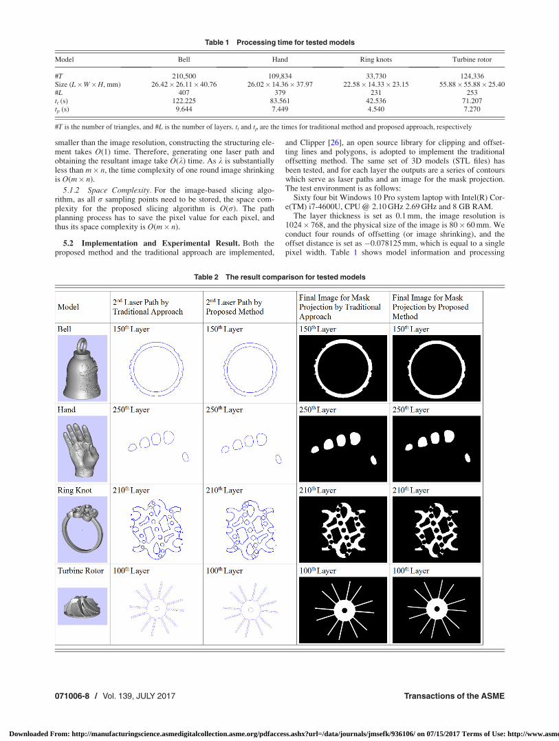
Table 2 The result comparison for tested models
071006-8 / Vol. 139, JULY 2017 Transactions of the ASME
Downloaded From: http://manufacturingscience.asmedigitalcollection.asme.org/pdfaccess.ashx?url=/data/journals/jmsefk/936106/ on 07/15/2017 Terms of Use: http://www.asme.org/about-asme/terms-of-use
times for all four models. The output comparison for a specificlayer is shown in Table 2. As can be seen from the tables, the pro-posed image-based slicing and path planning algorithm is tentimes faster than the traditional analytical method without losingaccuracy with respect to the printer resolution. However, it shouldbe noted that the image-based algorithm may not find obviousbenefit if the machine resolution is improved by more than tentimes with the advance of machine and process development inthe future.
6 Conclusion
The hybrid stereolithography process has the potential to sub-stantially increase the system throughput without losing the fabri-cation quality. Geometry processing operations such as thecontour slicing and the tool path planning are among the key pro-cedures of the hybrid process. The traditional analytical approachsuffers from multiple technical difficulties, including but not lim-ited to, high time complexity and low reliability due to the chal-lenge of maintaining geometry integrity. In this paper, weproposed a novel image-based numerical approach for slicing andtool path planning for the hybrid Stereolithography system. Sucha numerical approach converts the traditional continuous domain(e.g., contour) into a discrete domain (e.g., image) by accountingfor the limited hardware resolution. Therefore, the proposednumerical method is more configuration-specific than the tradi-tional analytical approach. Meanwhile, because of the nature ofparallel computation, the proposed image-based algorithm has thepotential to be implemented on the graphics processing unit(GPU), and thus, it is able to achieve higher computational effi-ciency. Both the theoretical analysis and the experimental valida-tion verified that the proposed approach can achieve highercomputational efficiency than the traditional technique withoutlosing the desired accuracy.
Acknowledgment
The authors gratefully appreciate the financial support fromNational Science Foundation (NSF) through CNS-1547167.
References[1] Gibson, I., Rosen, D. W., and Stucker, B., 2010, Additive Manufacturing Tech-
nologies: Rapid Prototyping to Direct Digital Manufacturing, Springer, NewYork.
[2] Nakamoto, T., and Yamaguchi, K., 1996, “Consideration on the Producing ofHigh Aspect Ratio Micro Parts Using UV Sensitive Photopolymer,” 7th Inter-national Symposium on Micro Machine and Human Science (IEEE), Nagoya,Japan, Oct. 2–4, pp. 53–58.
[3] Monneret, S., Loubere, V., and Corbel, S., 1999, “MicrostereolithographyUsing a Dynamic Mask Generator and a Non-Coherent Visible Light Source,”Proc. SPIE, 3680, pp. 553–561.
[4] Stampfl, J., Fouad, H., Seidler, S., Liska, R., Schwager, F., Woesz, A., andFratzl, P., 2004, “Fabrication and Moulding of Cellular Materials by Rapid Pro-totyping,” Int. J. Mater. Prod. Technol., 21(4), pp. 285–296.
[5] Xu, G., Zhao, W., Tang, Y., and Lu, B., 2011, “Novel Stereolithography Systemfor Small Size Objects,” Rapid Prototyping J., 12(1), pp. 12–17.
[6] Jiang, C.-P., 2010, “Accelerating Fabrication Speed in Two-Laser Beam Stereo-lithography System Using Adaptive Crosshatch Technique,” Int. J. Adv. Manuf.Technol., 50(9–12), pp. 1003–1011.
[7] Kang, H.-W., Park, J. H., and Cho, D.-W., 2012, “A Pixel Based SolidificationModel for Projection Based Stereolithography Technology,” Sens. Actuators A,178, pp. 223–229.
[8] Bourell, D. L., Leu, M. C., and Rosen, D. W., 2009, “Roadmap for AdditiveManufacturing: Identifying the Future of Freeform Processing,” The Roadmapfor Additive Manufacturing Workshop (RAM), Alexandra, VA, Mar. 30–31,pp. 1–102.
[9] Zhou, C., Ye, H., and Zhang, F., 2015, “A Novel Low-Cost StereolithographyProcess Based on Vector Scanning and Mask Projection for High-Accuracy,High-Speed, High-Throughput, and Large-Area Fabrication,” ASME J. Com-put. Inf. Sci. Eng., 15(1), p. 011003.
[10] Hughes, J. F., van Dam, A., McGuire, M., Sklar, D. F., Foley, J. D., Feiner, S.K., and Akeley, K., 2013, Computer Graphics: Principles and Practices, Addi-son-Wesley, Upper Saddle River, NJ.
[11] Choi, B. K., and Park, S. C., 1999, “A Pair-Wise Offset Algorithm for 2d Point-Sequence Curve,” Comput.-Aided Des., 31(12), pp. 735–745.
[12] Park, S. C., and Shin, H., 2002, “Polygonal Chain Intersection,” Comput.Graphics, 26(2), pp. 341–350.
[13] Chen, X., and McMains, S., 2005, “Polygon Offsetting by Computing WindingNumbers,” ASME Paper No. DETC2005-85513.
[14] de Berg, M., Cheong, O., van Kreveld, M., and Overmars, M., 2008, Computa-tional Geometry: Algorithms and Application, Springer, Berlin.
[15] Rock, S. J., and Wozny, M. J., 1991, “Utilizing Topological Information toIncrease Scan Vector Generation Efficiency,” International Solid Freeform Fab-rication Symposium (SFF), Austin, TX, Aug. 12–14, pp. 1–9.
[16] Kwok, T.-H., Ye, H., Chen, Y., Zhou, C., and Xu, W., 2016, “Mass Customiza-tion: Reuse of Digital Slicing for Additive Manufacturing,” ASME Paper No.DETC2016-60140.
[17] Ye, H., Zhou, C., and Xu, W., 2016, “Mass Customization: Reuse of TopologyInformation to Accelerate Slicing Process for Additive Manufacturing,” Inter-national Solid Freeform Fabrication Symposium (SFF), Austin, TX, Aug. 7–10,pp. 53–66.
[18] Botsch, M., Kobbelt, L., Pauly, M., Alliez, P., and L�evy, B., 2010, PolygonMesh Processing, A K Peters, Natick, MA.
[19] Huang, P., Wang, C. C. L., and Chen, Y., 2013, “Intersection-Free and Topo-logically Faithful Slicing of Implicit Solid,” ASME J. Comput. Inf. Sci. Eng.,13(2), p. 021009.
[20] Stelldinger, P., Latecki, L. J., and Siqueira, M., 2007, “Topological EquivalenceBetween a 3d Object and the Reconstruction of Its Digital Image,” IEEE Trans.Pattern Anal. Mach. Intell., 29(1), pp. 126–140.
[21] Rossignac, J. R., and Requicha, A. A. G., 1986, “Offsetting Operations in SolidModelling,” Comput. Aided Geom. Des., 3(2), pp. 129–148.
[22] Nadler, S. B., 1978. Hyperspaces of Sets: A Text With Research Questions,Marcel Dekker, New York.
[23] Sonka, M., Hlavac, V., and Boyle, R., 2008, Image Processing, Analysis, andMachine Vision, Thomson Learning, Toronto, ON, Canada.
[24] Engedy, I., and Horv�ath, G., 2009, “A Global, Camera-Based Mobile RobotLocalization,” 10th International Symposium of Hungarian Researchers onComputational Intelligence and Informatics (CINTI), Budapest, Nov. 12–14,pp. 217–228.
[25] Gonzalez, R. C., and Woods, R. E., 2007, Digital Image Processing, PrenticeHall, Upper Saddle River, NJ.
[26] Johnson, A., 2014, “Clipper,” accessed Dec. 20, 2016, http://www.angusj.com/delphi/clipper.php
[27] Huang, P., Wang, C. C. L., and Chen, Y., 2014, “Algorithms for layered manu-facturing in image space,” Advances in Computers and Information in Engi-neering Research, Vol. 1, ASME, New York, Chap. 15.
[28] Sun, C., Fang, N., Wu, D. M., and Zhang, X., 2005, “Projection Micro-Stereolithography Using Digital Micro-Mirror Dynamic Mask,” Sens. ActuatorsA, 121(1), pp. 113–120.
[29] Vatani, M., Rahimi, A. R., Brazandeh, F., and Nezhad, A. S., 2009, “AnEnhanced Slicing Algorithm Using Nearest Distance Analysis for Layer Man-ufacturing,” Int. J. of Mechanical, Aerospace, Industrial, Mechatronic and Man-ufacturing Engineering, 3(1), pp. 74–79.
Journal of Manufacturing Science and Engineering JULY 2017, Vol. 139 / 071006-9
Downloaded From: http://manufacturingscience.asmedigitalcollection.asme.org/pdfaccess.ashx?url=/data/journals/jmsefk/936106/ on 07/15/2017 Terms of Use: http://www.asme.org/about-asme/terms-of-use