Embed Size (px)
Citation preview
The TrimSmart™ LT2100
Thick Film Hybrid Trim System

GSI Lumonics
Semiconductor & Microelectronics
We turn roadmaps into reality.™
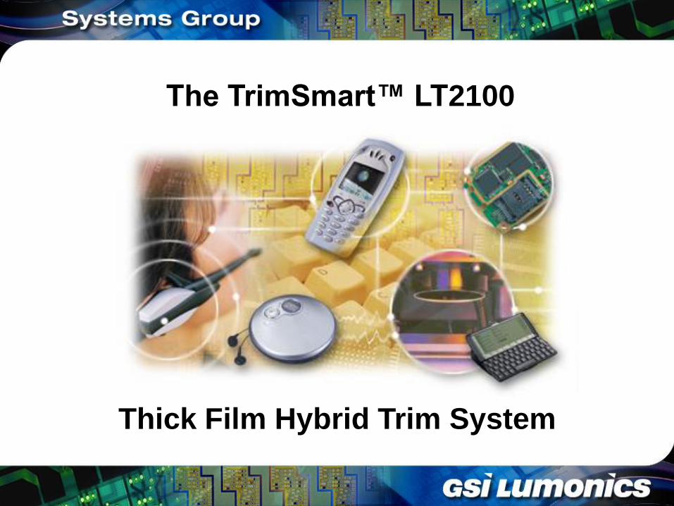
What is Laser Trim?
Laser Trim is a safe, highly accurate micromachining
technique which can be used to fine-tune electronic
circuits, components, and ICs.
GSI Lumonics provides a range of TrimSmart™ laser
trim solutions.
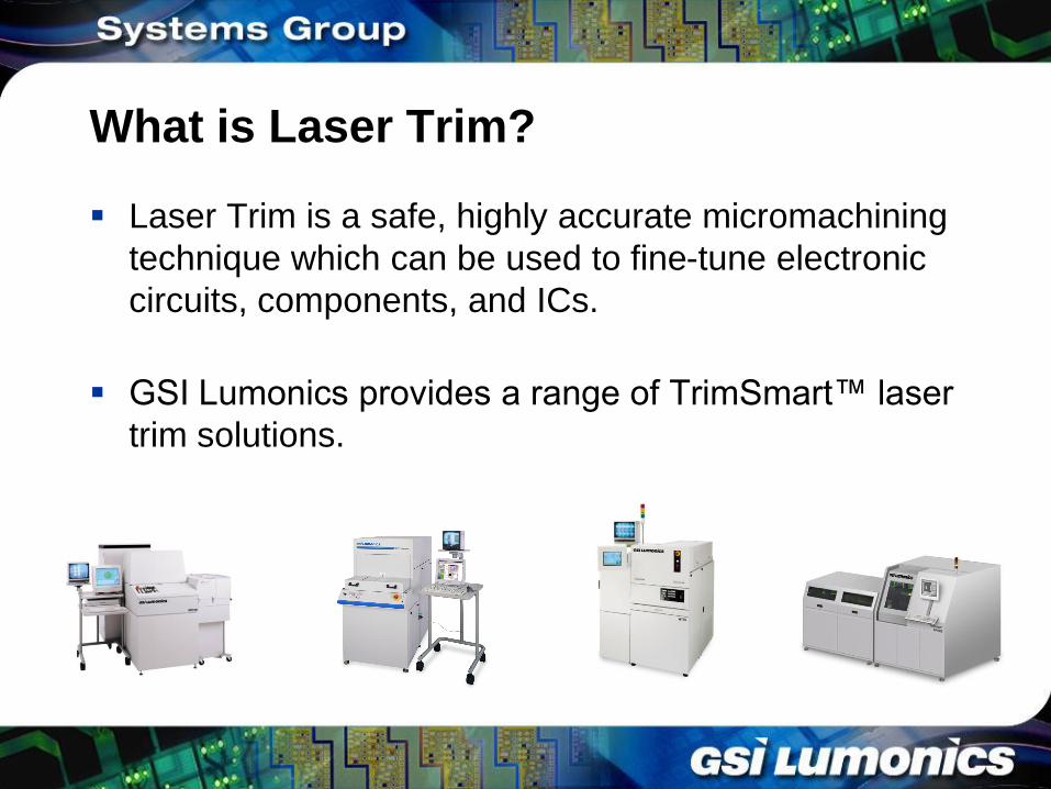
Introducing the TrimSmart™ LT2100
The ideal solution for trim and test of thick film components and circuits, including PCBs, SMT components, and hybrids.
Design guided by our customers.
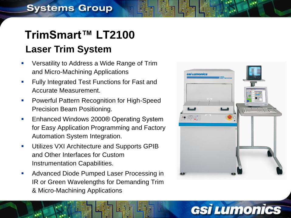
TrimSmart™ LT2100
Versatility to Address a Wide Range of Trim
and Micro-Machining Applications
Fully Integrated Test Functions for Fast and
Accurate Measurement.
Powerful Pattern Recognition for High-Speed
Precision Beam Positioning.
Enhanced Windows 2000® Operating System
for Easy Application Programming and Factory
Automation System Integration.
Utilizes VXI Architecture and Supports GPIB
and Other Interfaces for Custom
Instrumentation Capabilities.
Advanced Diode Pumped Laser Processing in
IR or Green Wavelengths for Demanding Trim
& Micro-Machining Applications
Laser Trim System
LT2100 – Advancements In Design
Modular System Design Allows for Field Upgrades and Application Changes – Includes Cutting Lenses, Lasers, and Laser Wavelengths
Windows 2000 Software Platform
Stiffer Frame for Greater Process Stability
Smaller Footprint for Decreased Facility Costs
Larger Work Area – Able to Process Devices up 10” x 12” in Size
New Heavy Duty Z Stage – Able to Handle Higher Probe Forces and Larger Parts
Motorized Z-adjustable Probe Frame – Computer Controlled Probe Height and Step Adjustment for Greater Probing Precision
New Beam Box – Modular, Multi-Wavelength Changeover for Greater Application Flexibility
Rotary Polarizer Laser Control for Greater Precision and Stability
Three Cutting Lenses to Choose From - 20µm to 50µm spot sizes.
New Latest Diode Pumped Laser Design with Single Fiber Module 40W Pump Design.
The LT2100 In Action
System & Subsystem
Descriptions
TrimSmart LT2100
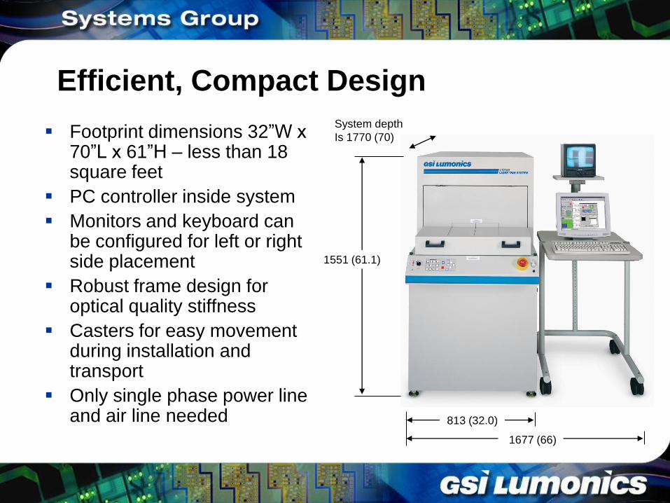
Efficient, Compact Design
Footprint dimensions 32”W x 70”L x 61”H – less than 18 square feet
PC controller inside system
Monitors and keyboard can be configured for left or right side placement
Robust frame design for optical quality stiffness
Casters for easy movement during installation and transport
Only single phase power line and air line needed
System depth
Is 1770 (70)
813 (32.0)
1551 (61.1)
1677 (66)
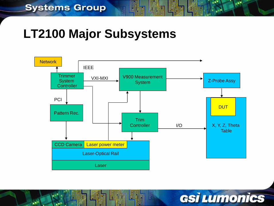
LT2100 Major Subsystems
Trimmer System
Controller Z-Probe Assy
X, Y, Z, Theta
Table
V900 Measurement
System
Laser-Optical Rail
Trim
Controller
Pattern Rec.
CCD Camera Laser power meter
VXI-MXI
PCI
I/O
IEEE
DUT
Network
Laser
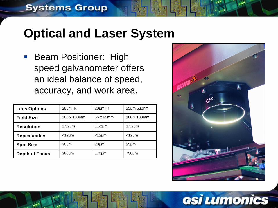
Optical and Laser System
Beam Positioner: High
speed galvanometer offers
an ideal balance of speed,
accuracy, and work area.
Lens Options 30µm IR 20µm IR 25µm 532nm
Field Size 100 x 100mm 65 x 65mm 100 x 100mm
Resolution 1.52µm 1.52µm 1.52µm
Repeatability <12µm <12µm <12µm
Spot Size 30µm 20µm 25µm
Depth of Focus 380µm 170µm 750µm
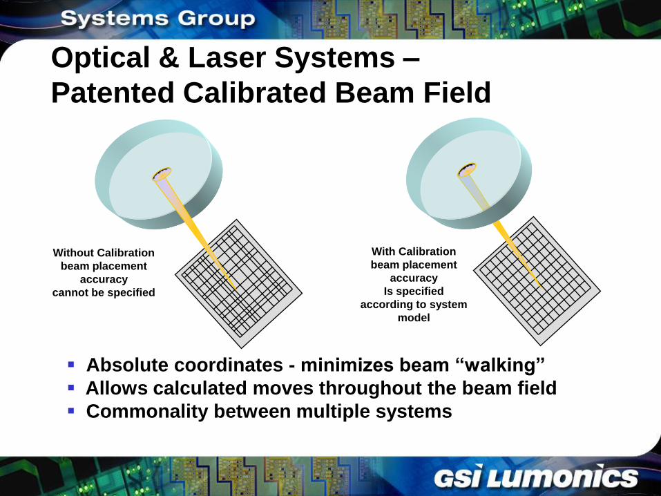
Optical & Laser Systems –
Patented Calibrated Beam Field
Without Calibration
beam placement
accuracy
cannot be specified
With Calibration
beam placement
accuracy
Is specified
according to system
model
Absolute coordinates - minimizes beam “walking”
Allows calculated moves throughout the beam field
Commonality between multiple systems
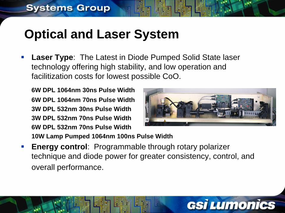
Optical and Laser System
Laser Type: The Latest in Diode Pumped Solid State laser
technology offering high stability, and low operation and
facilitization costs for lowest possible CoO.
6W DPL 1064nm 30ns Pulse Width
6W DPL 1064nm 70ns Pulse Width
3W DPL 532nm 30ns Pulse Width
3W DPL 532nm 70ns Pulse Width
6W DPL 532nm 70ns Pulse Width
10W Lamp Pumped 1064nm 100ns Pulse Width
Energy control: Programmable through rotary polarizer
technique and diode power for greater consistency, control, and
overall performance.
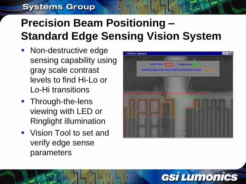
Precision Beam Positioning –
Standard Edge Sensing Vision System
Non-destructive edge
sensing capability using
gray scale contrast
levels to find Hi-Lo or
Lo-Hi transitions
Through-the-lens
viewing with LED or
Ringlight illumination
Vision Tool to set and
verify edge sense
parameters
search area target areas
trained images with coarse and fine granularity results
search area target areas
trained images with coarse and fine granularity results
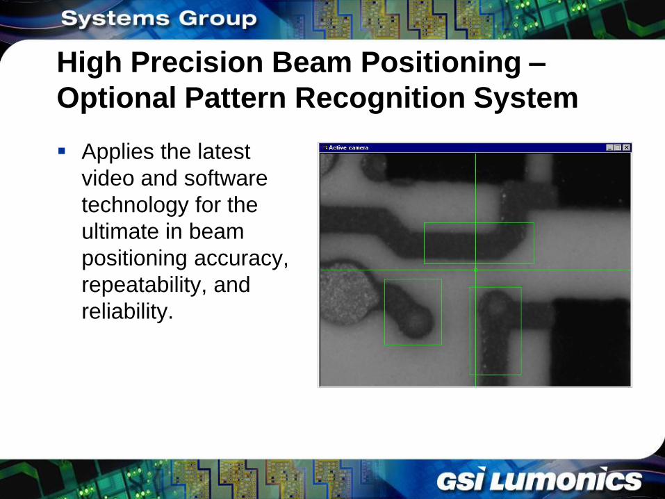
High Precision Beam Positioning –
Optional Pattern Recognition System
Applies the latest
video and software
technology for the
ultimate in beam
positioning accuracy,
repeatability, and
reliability.
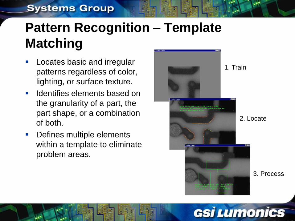
Pattern Recognition – Template
Matching
Locates basic and irregular
patterns regardless of color,
lighting, or surface texture.
Identifies elements based on
the granularity of a part, the
part shape, or a combination
of both.
Defines multiple elements
within a template to eliminate
problem areas.
1. Train
2. Locate
3. Process
Pattern Recognition – Ease of Use
Graphical tools and stored templates
expedite setup time:
– Allows for easy system training to understand,
interpret, and characterize images found on any
particular part, circuit, or substrate.
– Sets of pattern templates may be created for
multiple devices, stored in a library, and easily
loaded into a production program when needed.
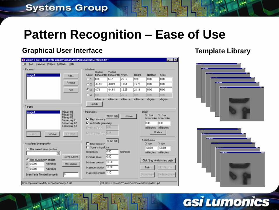
Pattern Recognition – Ease of Use Graphical User Interface Template Library
Pattern Recognition – Ensuring
Success
An estimated recognition success rate, based
on the uniqueness and specific parameters of
a target, may be obtained as part of the
system setup.
Synthetic targets can also be created when
actual parts are not available.
Characteristics of desired shapes can be
drawn from the library to create an ideal part.
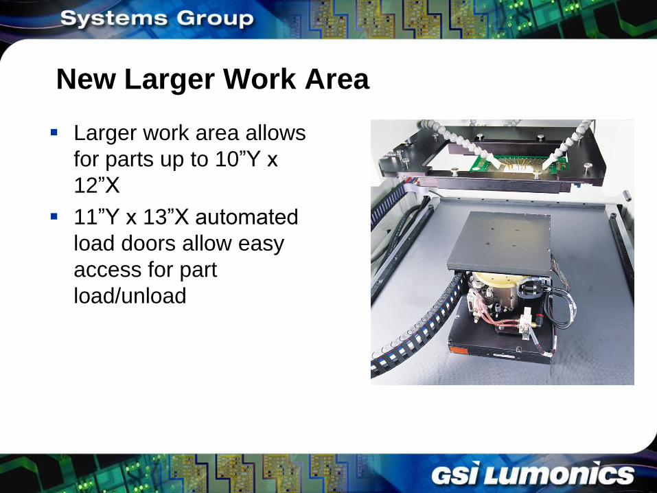
New Larger Work Area
Larger work area allows
for parts up to 10”Y x
12”X
11”Y x 13”X automated
load doors allow easy
access for part
load/unload
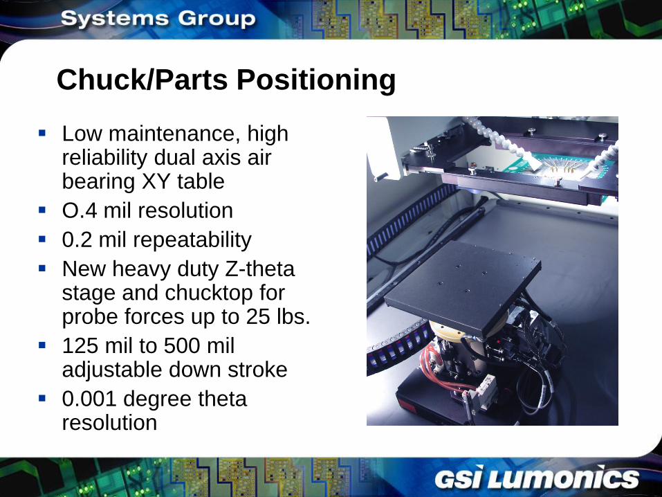
Chuck/Parts Positioning
Low maintenance, high reliability dual axis air bearing XY table
O.4 mil resolution
0.2 mil repeatability
New heavy duty Z-theta stage and chucktop for probe forces up to 25 lbs.
125 mil to 500 mil adjustable down stroke
0.001 degree theta resolution
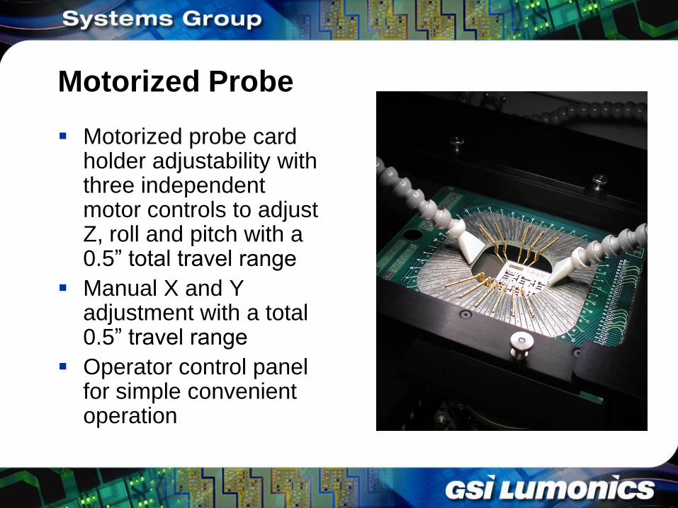
Motorized Probe
Motorized probe card holder adjustability with three independent motor controls to adjust Z, roll and pitch with a 0.5” total travel range
Manual X and Y adjustment with a total 0.5” travel range
Operator control panel for simple convenient operation
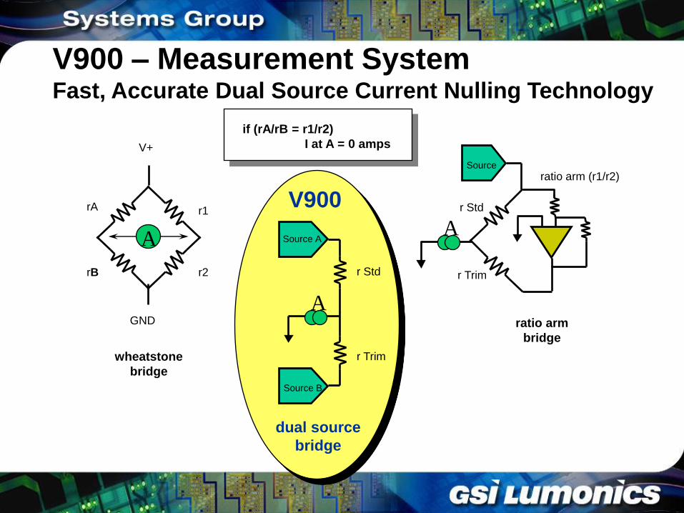
V900 – Measurement System Fast, Accurate Dual Source Current Nulling Technology
if (rA/rB = r1/r2)
I at A = 0 amps
rA
rB
r1
r2
A
V+
GND
wheatstone
bridge
r Std
r Trim
ratio arm (r1/r2) Source
A
ratio arm
bridge
Source A
Source B
A
r Std
r Trim
dual source
bridge
V900
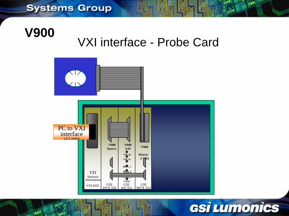
VXI
VXI-MXI
National Instruments
GSI DVS 350
V900
Matrix
3 X 24
V900
A/D
V900
Source
GSI AD 351
GSI MTX 352
PC to VXI interface
(AT-2000)
VM_hi
VM_lo
MUX_1
MUX_2 CMP_1
CMP_2
LSync
VXI interface - Probe Card V900
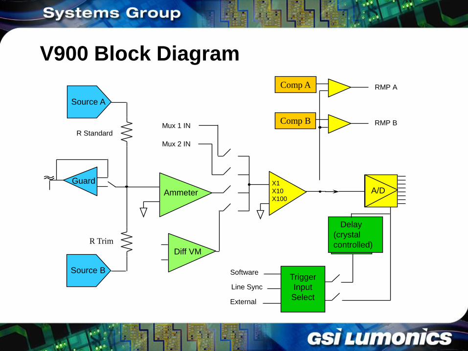
A/D
Comp A
Comp B
R Standard
R Trim
Delay
(crystal
controlled)
Trigger
Input
Select
Source A
Source B
Ammeter
Guard X1
X10
X100
Software
Line Sync
External
Diff VM
RMP A
RMP B
Mux 2 IN
Mux 1 IN
V900 Block Diagram
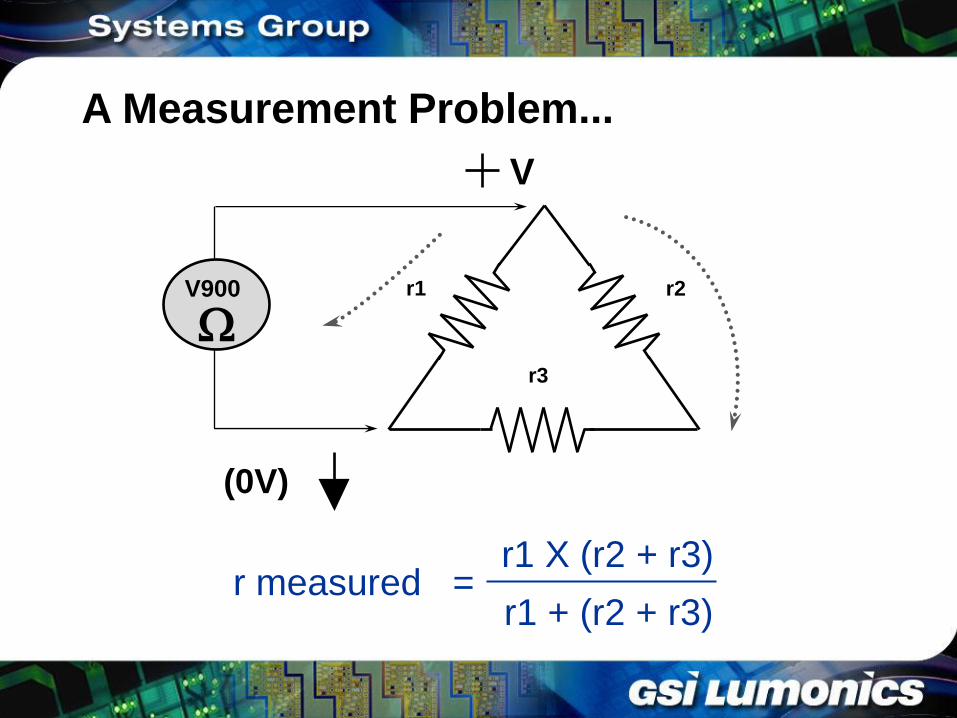
A Measurement Problem...
r1
r3
r2
r measured = r1 X (r2 + r3)
r1 + (r2 + r3)
V
(0V)
W V900
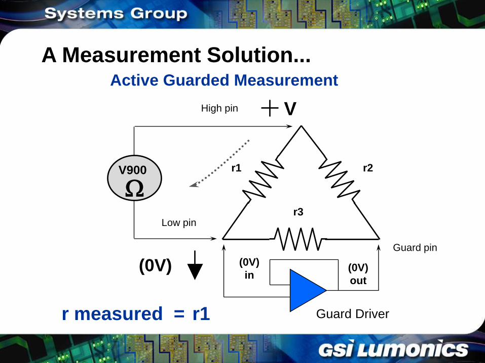
Active Guarded Measurement
r1
r3
r2
r measured = r1
V
(0V) (0V)
in (0V)
out
Guard Driver
Guard pin
Low pin
High pin
W V900
A Measurement Solution...
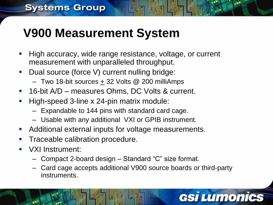
V900 Measurement System
High accuracy, wide range resistance, voltage, or current measurement with unparalleled throughput.
Dual source (force V) current nulling bridge:
– Two 18-bit sources + 32 Volts @ 200 milliAmps
16-bit A/D – measures Ohms, DC Volts & current.
High-speed 3-line x 24-pin matrix module:
– Expandable to 144 pins with standard card cage.
– Usable with any additional VXI or GPIB instrument.
Additional external inputs for voltage measurements.
Traceable calibration procedure.
VXI Instrument:
– Compact 2-board design – Standard “C” size format.
– Card cage accepts additional V900 source boards or third-party instruments.
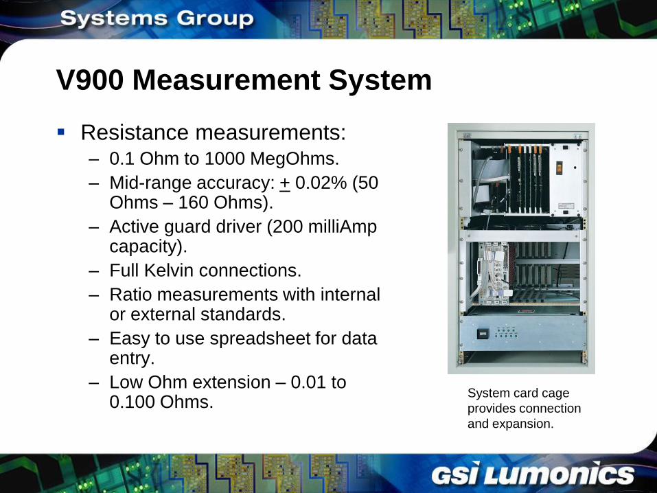
V900 Measurement System
Resistance measurements: – 0.1 Ohm to 1000 MegOhms.
– Mid-range accuracy: + 0.02% (50 Ohms – 160 Ohms).
– Active guard driver (200 milliAmp capacity).
– Full Kelvin connections.
– Ratio measurements with internal or external standards.
– Easy to use spreadsheet for data entry.
– Low Ohm extension – 0.01 to 0.100 Ohms.
System card cage
provides connection
and expansion.
V900 Measurement System
Functional applications: – DC Voltage measurements:
• 11 voltage ranges – 100 milliVolts to 160 Volts
• Accuracy + 0.01% to + 0.05%
– DC sourcing:
• Three ranges: + 4, + 16, & + 32 Volts
• Accuracy + 0.005%
• Programmable current limit – 40 or 200 milliAmps
– DC current measurement:
• 7 Ammeter ranges 2 microAmp to 200 milliAmps
• Accuracy + 1.5% to + 0.05%
– Comparator trim outputs.
– Selectable trigger event.
Instrument Compatibility
National Instruments MXI-VXI compatible
National Instruments GPIB compatible
National Instruments LabWindows CVI
compatible
Note: GSI Lumonics offers procurement &
integration of special measurement
equipment
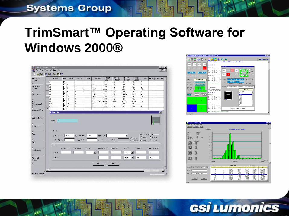
TrimSmart™ Operating Software for
Windows 2000®
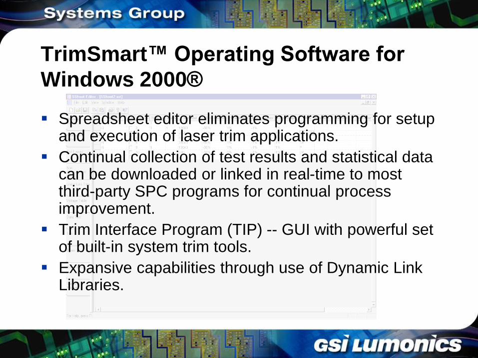
TrimSmart™ Operating Software for
Windows 2000®
Spreadsheet editor eliminates programming for setup and execution of laser trim applications.
Continual collection of test results and statistical data can be downloaded or linked in real-time to most third-party SPC programs for continual process improvement.
Trim Interface Program (TIP) -- GUI with powerful set of built-in system trim tools.
Expansive capabilities through use of Dynamic Link Libraries.
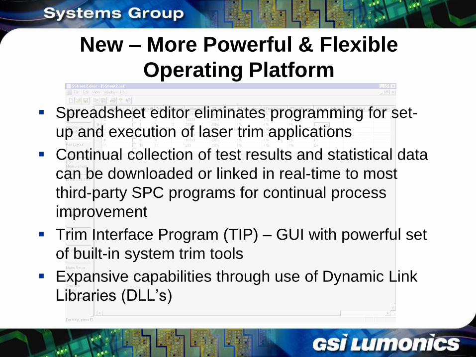
New – More Powerful & Flexible
Operating Platform
Spreadsheet editor eliminates programming for set-
up and execution of laser trim applications
Continual collection of test results and statistical data
can be downloaded or linked in real-time to most
third-party SPC programs for continual process
improvement
Trim Interface Program (TIP) – GUI with powerful set
of built-in system trim tools
Expansive capabilities through use of Dynamic Link
Libraries (DLL’s)
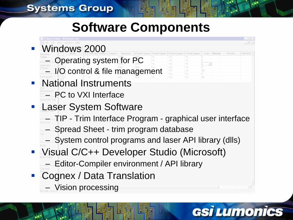
Software Components
Windows 2000 – Operating system for PC
– I/O control & file management
National Instruments – PC to VXI Interface
Laser System Software – TIP - Trim Interface Program - graphical user interface
– Spread Sheet - trim program database
– System control programs and laser API library (dlls)
Visual C/C++ Developer Studio (Microsoft) – Editor-Compiler environment / API library
Cognex / Data Translation – Vision processing
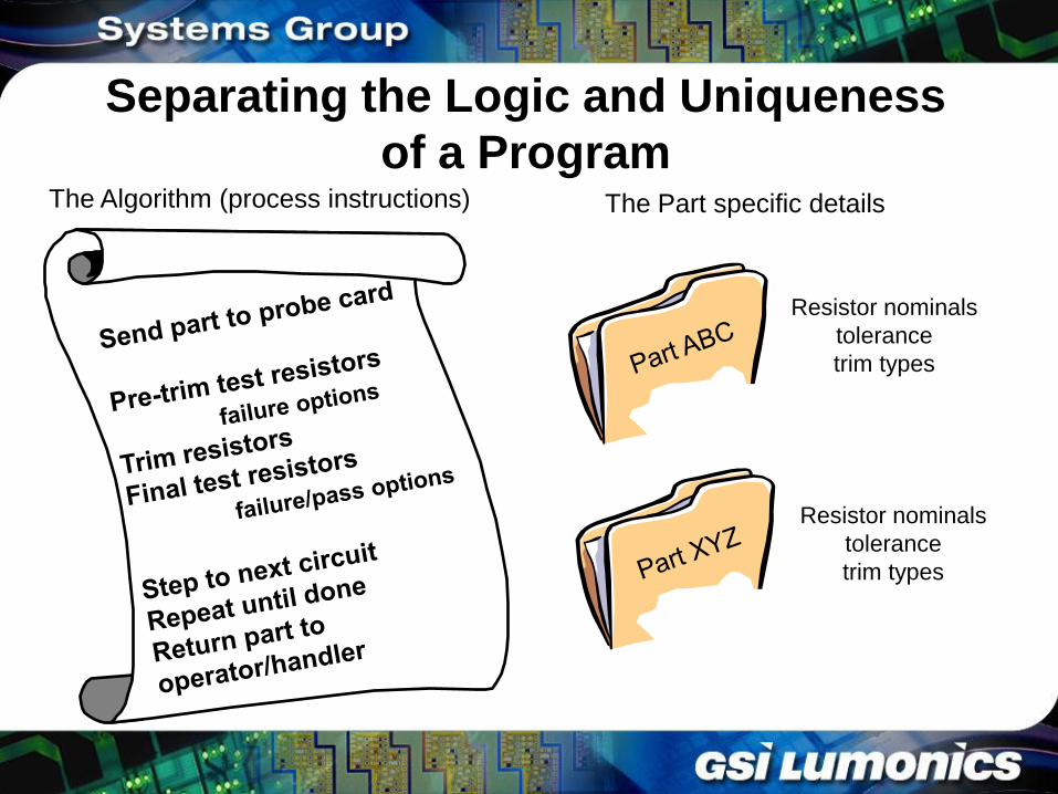
Separating the Logic and Uniqueness
of a Program The Algorithm (process instructions)
Resistor nominals
tolerance
trim types
Resistor nominals
tolerance
trim types
The Part specific details
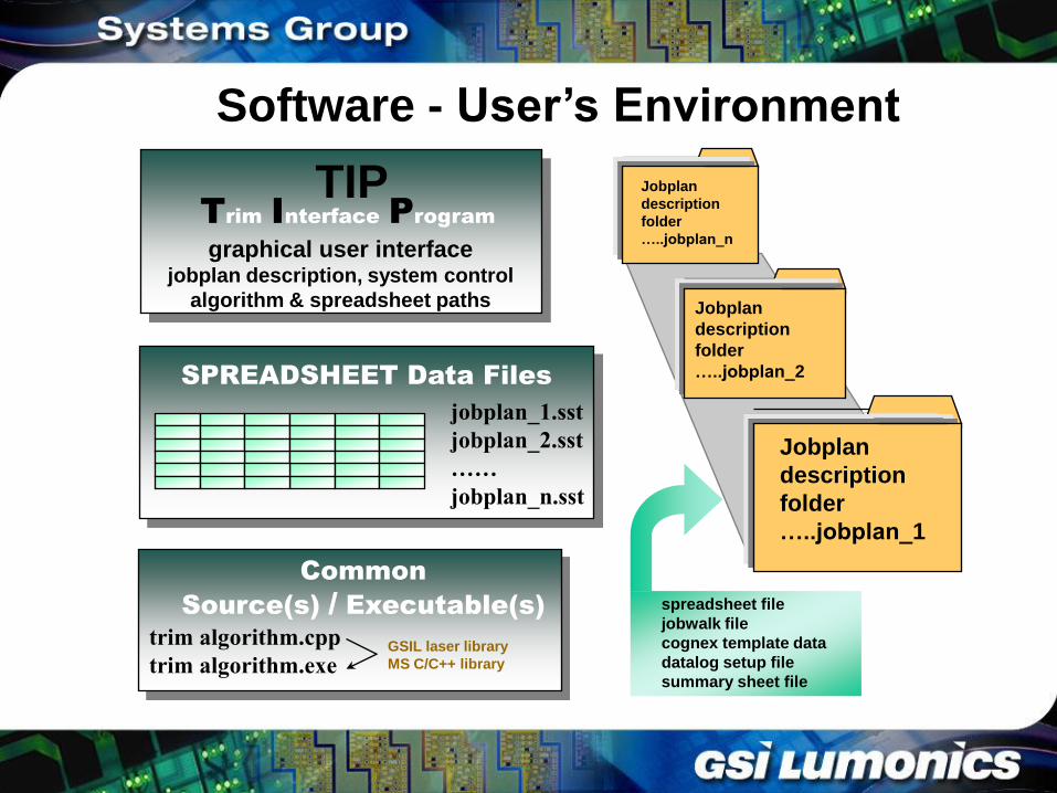
Common
Source(s) / Executable(s)
trim algorithm.cpp
trim algorithm.exe GSIL laser library
MS C/C++ library
SPREADSHEET Data Files
jobplan_1.sst
jobplan_2.sst
……
jobplan_n.sst
Jobplan
description
folder
…..jobplan_n
Jobplan
description
folder
…..jobplan_2
Jobplan
description
folder
…..jobplan_1
spreadsheet file
jobwalk file
cognex template data
datalog setup file
summary sheet file
Trim Interface Program
graphical user interface jobplan description, system control
algorithm & spreadsheet paths
TIP
Software - User’s Environment
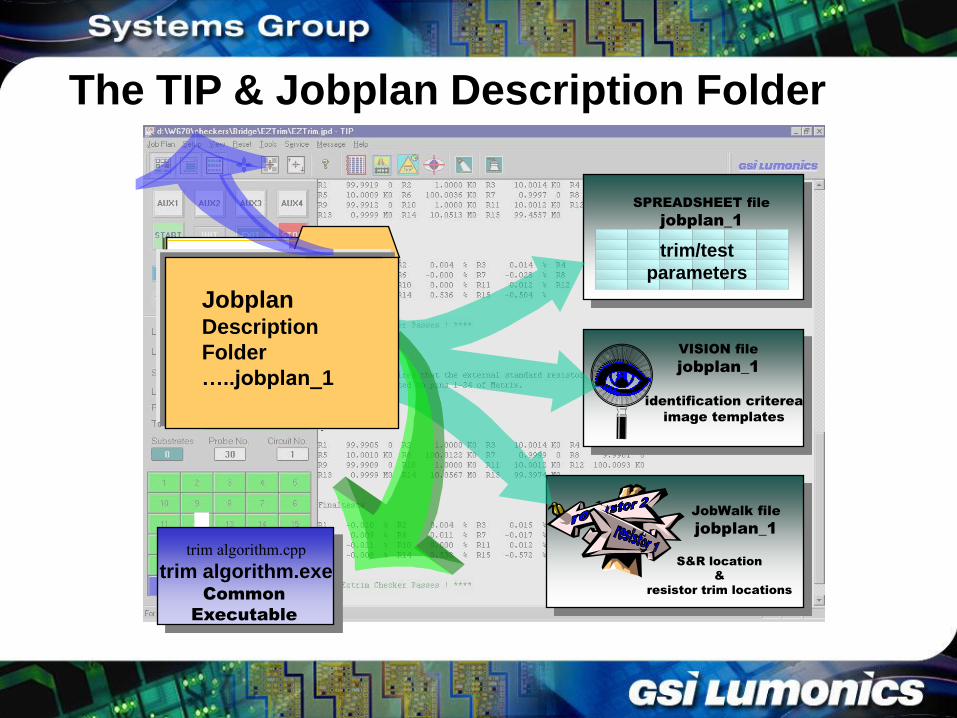
Common
Executable
trim algorithm.cpp
trim algorithm.exe
SPREADSHEET file
jobplan_1
trim/test
parameters
identification criterea
image templates
VISION file
jobplan_1
S&R location
&
resistor trim locations
JobWalk file
jobplan_1
Jobplan Description
Folder
…..jobplan_1
The TIP & Jobplan Description Folder
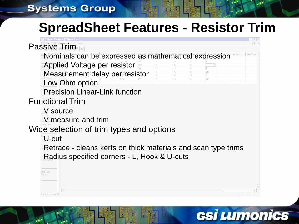
SpreadSheet Features - Resistor Trim
Passive Trim Nominals can be expressed as mathematical expression
Applied Voltage per resistor
Measurement delay per resistor
Low Ohm option
Precision Linear-Link function
Functional Trim V source
V measure and trim
Wide selection of trim types and options U-cut
Retrace - cleans kerfs on thick materials and scan type trims
Radius specified corners - L, Hook & U-cuts
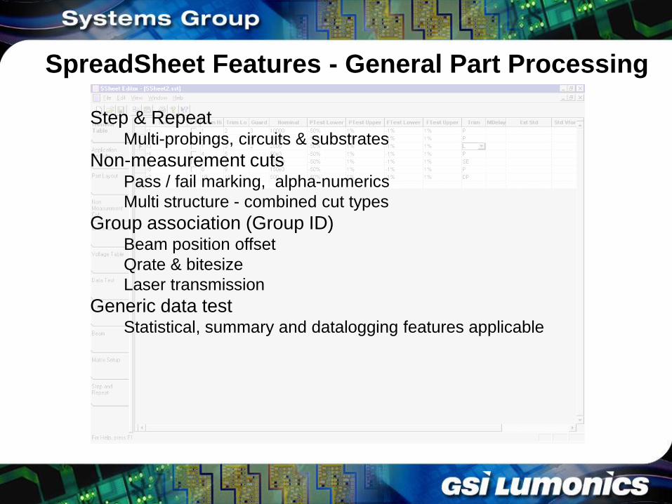
SpreadSheet Features - General Part Processing
Step & Repeat Multi-probings, circuits & substrates
Non-measurement cuts Pass / fail marking, alpha-numerics
Multi structure - combined cut types
Group association (Group ID) Beam position offset
Qrate & bitesize
Laser transmission
Generic data test Statistical, summary and datalogging features applicable
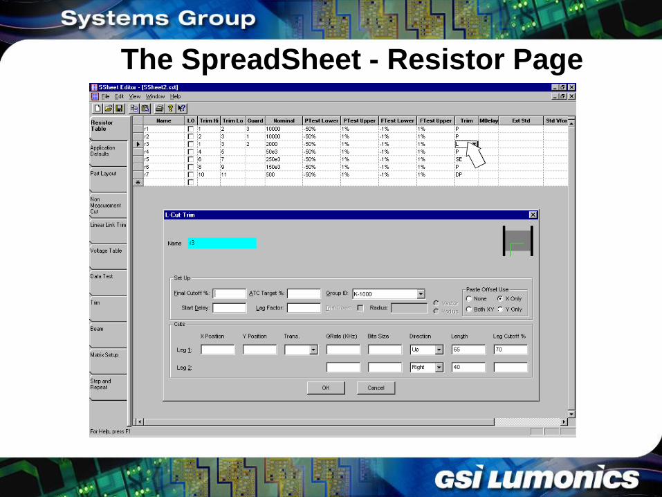
The SpreadSheet - Resistor Page
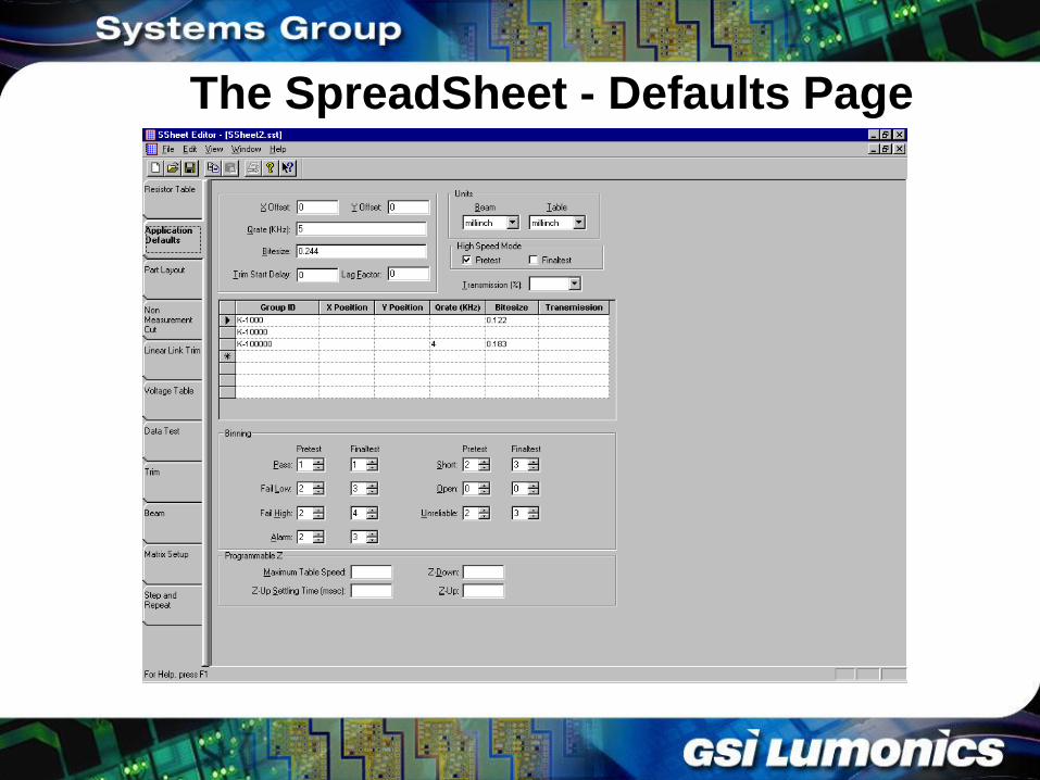
The SpreadSheet - Defaults Page
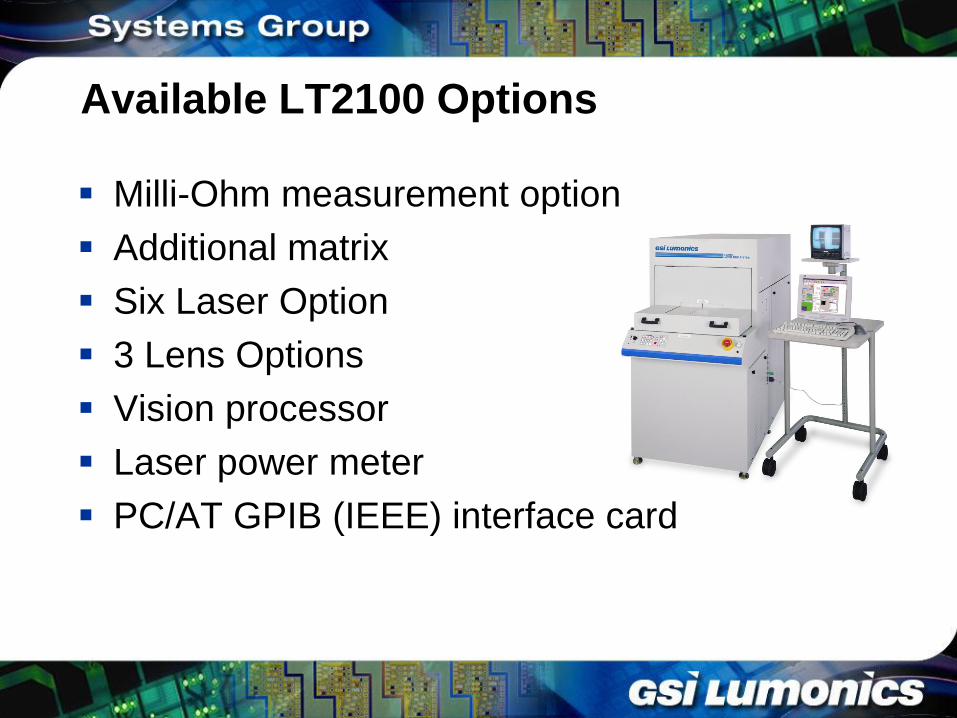
Available LT2100 Options
Milli-Ohm measurement option
Additional matrix
Six Laser Option
3 Lens Options
Vision processor
Laser power meter
PC/AT GPIB (IEEE) interface card
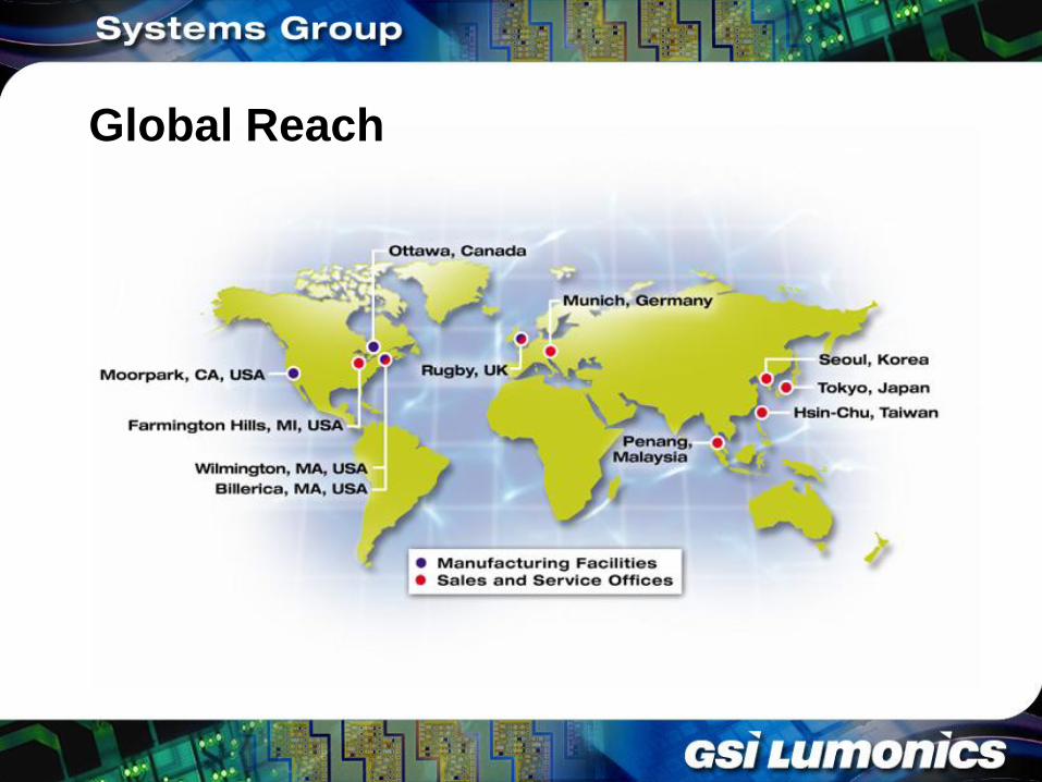
Global Reach
Conclusion
Modular, Versatile System to Meet Widest
Possible Range of Applications
Stiffer Frame for Greater Process Stability
Smaller Footprint for Reduced Facility Costs
Wider Range of Features for Greater Process
Flexibility and Ease of Use
Windows 2000 Software Platform
Global Application and Service Support