Embed Size (px)
Citation preview
The TCP/IP Protocol Suite Tutorial
December 20, 2006
Trademarks and Copyrights
Microsoft®, Windows®, Outlook®, and Internet Explorer® are registered trademarks or trademarks of Microsoft Corporation in the United States and/or other countries.
AOL®, AOL® Instant messenger™ and AIM® are trademarks or registered trademarks of America Online, Incorporated.
Yahoo!® and the Yahoo! logo are registered trademarks of Yahoo, Inc.
Acrobat® and Acrobat Reader® are a registered trademarks of Adobe Systems, Incorporated.
All other products or services mentioned in this dcompanies that market those products or servicedirectly to those companies
This document and its contents are provided by F“as is” with no warranties or representations whamerchantability and fitness for purpose. FNC doe
Furthermore, the contents of this document are swithout notice, to make changes in equipment dethis document may be copied, modified, or otherw
Unpublis Copyrigh
ocument are identified by the trademarks, service s or own those marks. Inquiries concerning such p
ujitsu Network Communications, Inc. (FNC) for guitsoever, either express or implied, including withous not warrant or represent that the contents of this
ubject to update and change at any time without nsign or components as progress in engineering mise reproduced without the express written conse
hed work and only distributed under restriction.t © Fujitsu Network Communications, Inc. All Rights
marks, or product names as designated by the roducts, services, or marks should be made
dance purposes only. This document is provided t limitation the implied warranties of document are error free.
otice by FNC, since FNC reserves the right, ethods may warrant. No part of the contents of nt of FNC.
Reserved.
Release 1.0, December 20, 2006 i
Table of ContentsTCP/IP Protocol Suite Tutorial
Fujitsu and Fujitsu Customer Use Only
Introduction...............................................................................1-1Objectives.............................................................................1-1Standards .............................................................................1-1Distribution Method ..............................................................1-1Optional Reading..................................................................1-1
The OSI Reference Model ........................................................1-3Purpose ................................................................................1-3
The TCP/IP Protocol Suite........................................................1-5Before We Begin.......................................................................1-7The Application Layer ...............................................................1-8
Application Layer Examples .................................................1-8The Transport Layer .................................................................1-9
User Datagram Protocol.......................................................1-9Transmission Control Protocol ...........................................1-10
The Internet Layer ..................................................................1-14The Internet Protocol ..............................................................1-15IP Routing...............................................................................1-19Address Resolution Protocol ..................................................1-20The Network Access Layer.....................................................1-21Point-to-Point Protocol............................................................1-23Ethernet ..................................................................................1-25A TCP/IP Networking Example...............................................1-29Wireless Fidelity......................................................................1-36Worldwide Interoperability for Microwave Access ..................1-40Frame Relay ...........................................................................1-44Asynchronous Transfer Mode.................................................1-47Multiprotocol Label Switching .................................................1-52Tutorial Review.......................................................................1-55Review Answers .....................................................................1-59
Glossary
ii Release 1.0, December 20, 2006
List of FiguresTCP/IP Protocol Suite Tutorial
Fujitsu and Fujitsu Customer Use Only
Figure 1-1: The OSI Reference Model..................................... 1-2Figure 1-2: Comparing the OSI and TCP/IP Models ............... 1-4Figure 1-3: Encapsulation........................................................ 1-6Figure 1-4: The UDP Packet Structure .................................... 1-9Figure 1-5: TCP Packet Structure.......................................... 1-12Figure 1-6: Classful Addressing............................................. 1-15Figure 1-7: NAT ..................................................................... 1-16Figure 1-8: The IP Packet Structure ...................................... 1-18Figure 1-9: The Point-to-Point Protocol Frame...................... 1-22Figure 1-10: Ethernet Frame Formats ................................... 1-24Figure 1-11: PPP Encapsulated in an Ethernet Frame.......... 1-28Figure 1-12: TCP/IP Example................................................ 1-29Figure 1-13: Communicating at the Application Level ........... 1-29Figure 1-14: Using TCP to Transport HTTP Messages......... 1-30Figure 1-15: Using DNS to Resolve Hostnames ................... 1-30Figure 1-16: Establishing a TCP/IP Connection .................... 1-31Figure 1-17: Invoking the IP Protocol .................................... 1-31Figure 1-18: Using ARP to Determine MAC Addresses ........ 1-32Figure 1-19: Using Ethernet to Transmit an IP Datagram ..... 1-32Figure 1-20: Sending the Frame to the Default Gateway ...... 1-33Figure 1-21: Routing the Frame to the Final Destination....... 1-34Figure 1-22: The 802.11 MAC Frame Format ....................... 1-35Figure 1-23: WiMAX MAC PDU Format ................................ 1-39Figure 1-24: Frame Relay Packet Structure .......................... 1-43Figure 1-25: ATM Cell Structure ............................................ 1-46Figure 1-26: Mixed Service Types on an MPLS Core ........... 1-51Figure 1-27: The MPLS Label Stack...................................... 1-54
The TCP/IP Protocol SuiteTutorial
IntroductionThis self-study tutorial satisfies the prerequisite for Transmission Control Protocol/Internet Protocol (TCP/IP) networking knowledge that is required for attendance at Fujitsu Network Communications Inc. (FNC) Educational Services data networking product training classes.
ObjectivesAfter completing this lesson, the student should be able to:
• Describe the OSI 7-layer networking model
• Describe the TCP/IP networking model
• Define basic networking terminology
• Understand the various TCP/IP networking components
• Identify the relationships between the components of the TCP/IP protocol suite
StandardsThe student can complete the tutorial and take the self evaluation at the end of the tutorial. If the student passes the tutorial, the FNC prerequisite qualification for data networking is complete. If the student does not pass the tutorial, sections in the tutorial relating to questions missed should be reviewed. Each student should be familiar with concepts and terms of the tutorial prior to attending class.
Distribution MethodThe data networking tutorial is available at the following Internet address:
http://www.fujitsu.com/us/services/telecom/training/ edservtcpip.pdf
The tutorial can be viewed using Acrobat® Reader®.
Optional ReadingFNC-500-0005-010, Guide to ATM
ATM Tutorial
Ethernet Tutorial
The referenced optional reading can be downloaded by going to the following URL:
http://www.fujitsu.com/us/services/telecom/training/
Release 1.0, December 20, 2006 1-1Fujitsu and Fujitsu Customer Use Only
TutorialThe TCP/IP Protocol Suite
Figure 1-1: The OSI Reference Model
1-2 Release 1.0, December 20, 2006Fujitsu and Fujitsu Customer Use Only
The TCP/IP Protocol SuiteTutorial
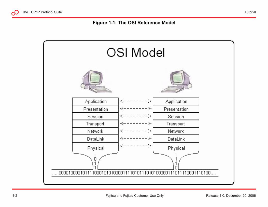
The OSI Reference ModelAs many networking tutorials do, this one begins with an introduction to the Open Systems Interconnection (OSI) Reference Model (OSI Model). The OSI model is a layered, abstract description for communication and computer network protocol design, developed as part of the Open Systems Interconnection initiative. It is also called the OSI 7-layer model.
PurposeThe OSI model divides the functions of a protocol into a series of layers. Each layer has the property that it only uses the functions of the layer directly below, and only exports functionality to the layer directly above. A system that implements protocol behavior consisting of a series of these layers is known as a protocol stack or simply stack. Protocol stacks can be implemented either in hardware or software, or a mixture of both. Typically, only the lower layers are implemented in hardware, with the higher layers being implemented in software.
Application Layer
The application layer provides a means for the user to access information on the network through an application. This layer is the main interface for users to interact with the application and therefore the network.
Presentation Layer
The presentation layer transforms data to provide a standard interface for the application layer. Encoding, data compression, data encryption and similar manipulation of the presentation is done at this layer to present the data as a service or protocol developer sees fit.
Session Layer
The session layer controls the connections (sessions) between computers. It establishes, manages and terminates the connections between the local and remote application.
Transport Layer
The transport layer provides transparent transfer of data between end users, thus relieving the upper layers from transfer concerns while providing reliable data transfer. The transport layer controls the reliability of a given link through flow control, segmentation/desegmentation, and error control.
Network Layer
The network layer provides the means of transferring data sequences from a source to a destination by using one or more networks while maintaining the quality of service requested by the Transport layer. The Network layer performs network routing functions, and might also perform segmentation/de-segmentation, and report delivery errors.
Data Link Layer
The data link layer provides the means to transfer data between network entities and to detect and possibly correct errors that may occur in the Physical layer. It arranges bits from the physical layer into logical chunks of data, known as frames.
Physical Layer
The physical layer defines all the electrical and physical specifications for devices. This includes the layout of pins, voltages, and cable specifications.
Release 1.0, December 20, 2006 1-3Fujitsu and Fujitsu Customer Use Only
TutorialThe TCP/IP Protocol Suite
Figure 1-2: Comparing the OSI and TCP/IP Models
1-4 Release 1.0, December 20, 2006Fujitsu and Fujitsu Customer Use Only
The TCP/IP Protocol SuiteTutorial
The TCP/IP Protocol SuiteThe TCP/IP protocol suite, also referred to as the Internet protocol suite, is the set of communications protocols that implements the protocol stack on which the Internet and most commercial networks run. It is named after the two most important protocols in the suite: the Transmission Control Protocol (TCP) and the Internet Protocol (IP).
The TCP/IP protocol suite—like the OSI reference model—is defined as a set of layers. Upper layers are logically closer to the user and deal with more abstract data, relying on lower layer protocols to translate data into forms that are transmitted physically over the network.
The TCP/IP protocol is the primary focus of this tutorial.
TCP/IP Model and the OSI Reference Model
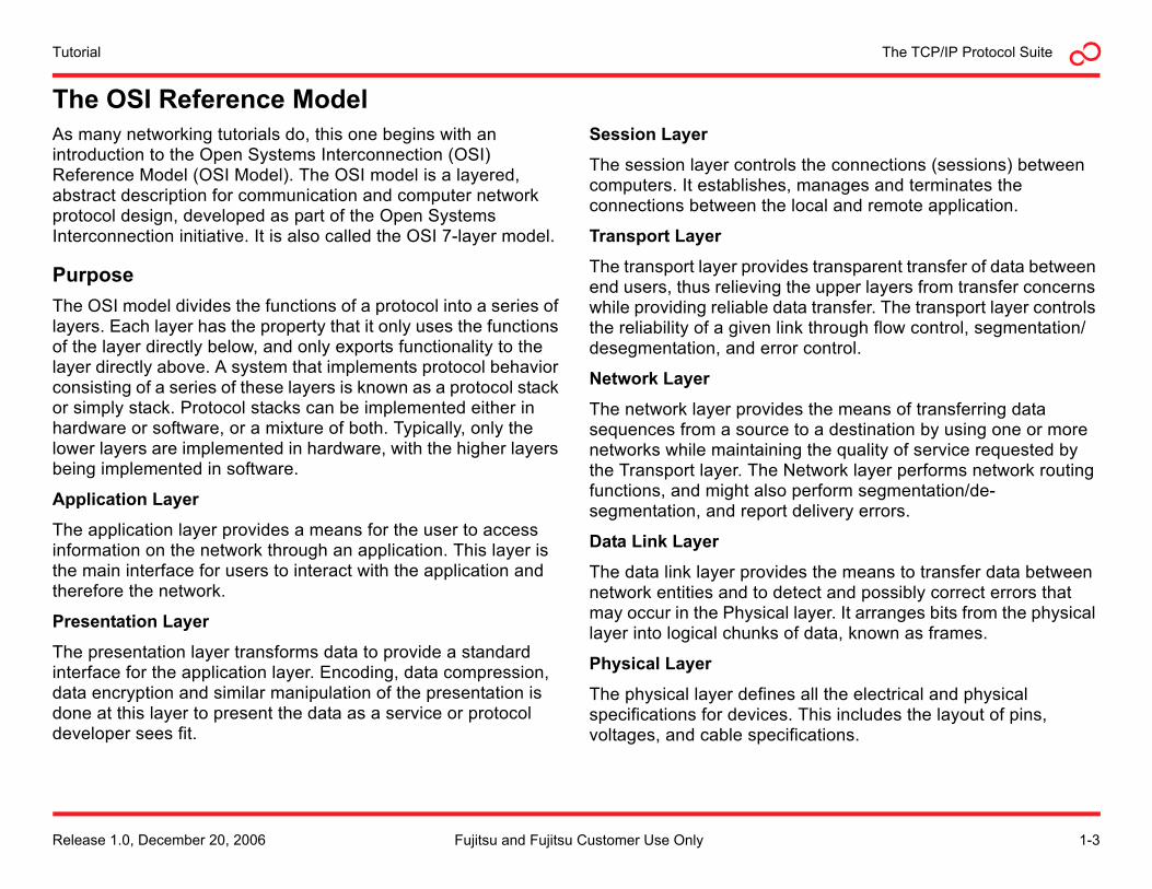
The TCP/IP protocol suite was developed before the OSI reference model. As such, it does not directly map to the 7-layer OSI reference model. The TCP/IP protocol stack has only layers that can be loosely mapped to the OSI protocol stack, as shown in Figure 1-2.
Application Layer
The application layer of the TCP/IP model corresponds to the application layer of the OSI reference model.
Some well known examples of application level entities within the TCP/IP domain are:
• FTP/Telnet/SSH
• HTTP/Secure HTTP (SHTTP)
• POP3/SMTP
• SNMP
Transport Layer
The transport layer of the TCP/IP model maps fairly closely to the transport layer of the OSI model. Two commonly used transport layer entities are TCP and User Datagram Protocol (UDP)
Internet Layer
The Internet layer of the TCP/IP model maps to the network layer of the OSI model. Consequently, the Internet layer is sometimes referred to as the network layer. The primary component of the Internet layer is the Internet Protocol (IP).Many of the TCP/IP routing protocols are also classified as part of the Internet layer.
Network Access Layer
The lowest layer of the TCP/IP protocol stack is the network access layer. The network access layer contains two sublayers, the media access control (MAC) sublayer and the physical sublayer. The MAC sublayer aligns closely with the data link layer of the OSI model, and is sometimes referred to by that name. The physical sublayer aligns with the physical layer of the OSI model.
Note: Some references divide the TCP/IP model into 5 layers, with the MAC and physical layers occupying the lowest two layers.
Examples of the network access layer that will be discussed in this tutorial include:
• Ethernet
• Wireless Fidelity (Wi-FI)/WiMAX
• PPP, PPP over Ethernet (PPPoE)
• ATM/Frame Relay
Release 1.0, December 20, 2006 1-5Fujitsu and Fujitsu Customer Use Only
TutorialThe TCP/IP Protocol Suite
Figure 1-3: Encapsulation
1-6 Release 1.0, December 20, 2006Fujitsu and Fujitsu Customer Use Only
The TCP/IP Protocol SuiteTutorial
Before We Begin...In order to better understand the operation of the TCP/IP protocol suite, some important concepts and terms should be understood beforehand.
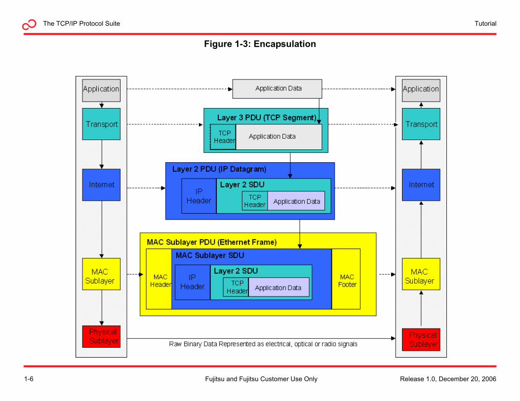
Encapsulation
In computer networking, encapsulation means including data from an upper layer protocol into a lower layer protocol. This is a method of abstraction for networking that allows different layers to add features/functionality. Figure 1-3 illustrates the concept of encapsulating data from one layer within data passed to another.
Protocol Data Unit
In networking, protocol data unit (PDU) is a generic term for information that is delivered to the next lower level in the protocol stack.
Service Data Unit
The service data unit (SDU) is the data that a layer receives from the layer above. Generally speaking, the PDU for one layer becomes the SDU of the next lower layer.
Packet
In the generic sense, a packet is a formatted block of information carried by a computer network. A packet typically consists of three elements: a header, the payload, and a trailer.
In the context of defining a protocol, a packet is used to pass information between layers of the stack. The packet payload contains the peer-exchanged PDU data. In this way, the packet can be thought of an envelope. The payload contains the PDU and the header provides delivery instructions to be used by the lower levels of the stack.
Datagram
The terms datagram and packet are often used interchangeably. However, in the strictest sense, a datagram is a packet that is not transmitted reliably through the network. More specifically the datagram is the PDU used by UDP and IP.
Segment
A segment is the unit of data exchanged by TCP peers. It is encapsulated in a TCP packet and passed to the internet protocol (IP).
Frame
A frame is a data block of fixed or variable length which has been formatted and encoded for digital transmission over a node-to-node link. Frames typically are used from the MAC sublayer downward. A frame can be thought of as the physical envelope that delivers an upper level packet or datagram.
Cell
A cell is a 53-byte fixed-length MAC sublayer PDU used by Asynchronous Transfer Mode (ATM) networks. It serves the same purpose as the frames used in Ethernet and Frame Relay networks.
Release 1.0, December 20, 2006 1-7Fujitsu and Fujitsu Customer Use Only
TutorialThe TCP/IP Protocol Suite
The Application LayerThe application layer is the topmost level of the TCP/IP protocol suite. It receives data from user applications and issues requests to the transport layer. The details of moving data between the application and other computers is shielded by the underlying layers.
Application Layer ExamplesApplications that pass data between computers on networks are considered part of the application layer domain. Within the application layer, additional protocols may be used by applications to interface with the transport layer.
For example, a Web browser such as Microsoft® Internet Explorer® exists at the application layer. The Hypertext Transfer Protocol (HTTP) is incorporated into browsers to facilitate communicating with Web sites by invoking transport layer services.
e-mail programs, such as Microsoft® Outlook® depend on application-level protocols such as the post office protocol (POP) or the Simple Mail Transfer Protocol (SMTP) to interface with the transport layer.
Application layer examples include:
• AIM®, AOL® Instant MessengerTM Protocol
• BitTorrent
• Domain Name Service (DNS)
• Dynamic Host Configuration Protocol (DHCP)
• File Transfer Protocol (FTP)
• Hypertext Transfer Protocol (HTTP)
• Internet Message Access Protocol (IMAP)
• Internet Relay Chat (IRC)
• Post Office Protocol Version 3 (POP3)
• Network Time Protocol (NTP)
• Simple Mail Transfer Protocol (SMTP)
• Simple Network Management Protocol (SNMP)
• Terminal Emulation Protocol (Telnet)
• Uniform Resource Locator (URL)
• Yahoo!® Messenger Protocol
As the TCP/IP application layer maps to the OSI application, presentation and session layers, it is also responsible for details such as character formats (For example, ASCII vs. EBCDIC) and basic encryption.
1-8 Release 1.0, December 20, 2006Fujitsu and Fujitsu Customer Use Only
The TCP/IP Protocol SuiteTutorial
The Transport LayerWithin the TCP/IP protocol suite, the two most common transport layer entities are the UDP and the TCP.
User Datagram ProtocolThe User Datagram Protocol is very simple. The PDU used by UDP is called a datagram. Datagrams are considered unreliable, in that there is no guarantee datagrams will be received in the correct order, if at all. If reliability of the information transmitted is needed, UDP should not be used.
While UDP is unreliable, the lack of error checking and correction make UDP fast and efficient for many less data intensive or time-sensitive applications, such as the Domain Name Service (DNS), the Simple Network Management Protocol (SNMP), the Dynamic Host Configuration Protocol (DHCP) and the Routing Information Protocol (RIP). UDP is also well suited for streaming video.
Basic Protocol Operation
The UPD protocol is simple in operation. When invoked by the application layer, the UDP protocol performs the following operations:
1. Encapsulates the user data into UDP datagrams
2. Passes the datagram to the IP layer for transmission
At the opposite end, the UDP datagram is passed up to UDP from the IP layer. UDP then removes the user data from the datagram and presents it upward to the application layer.
Ports
A port is a number that identifies the application using the UDP service. It can be thought of as an address for applications. For example, the application level protocols used for e-mail, POP3
and SMTP, are assigned standard port numbers. The port number is used by the UDP client on the receiving end to know what application to pass user data to.
The UDP Packet Structure
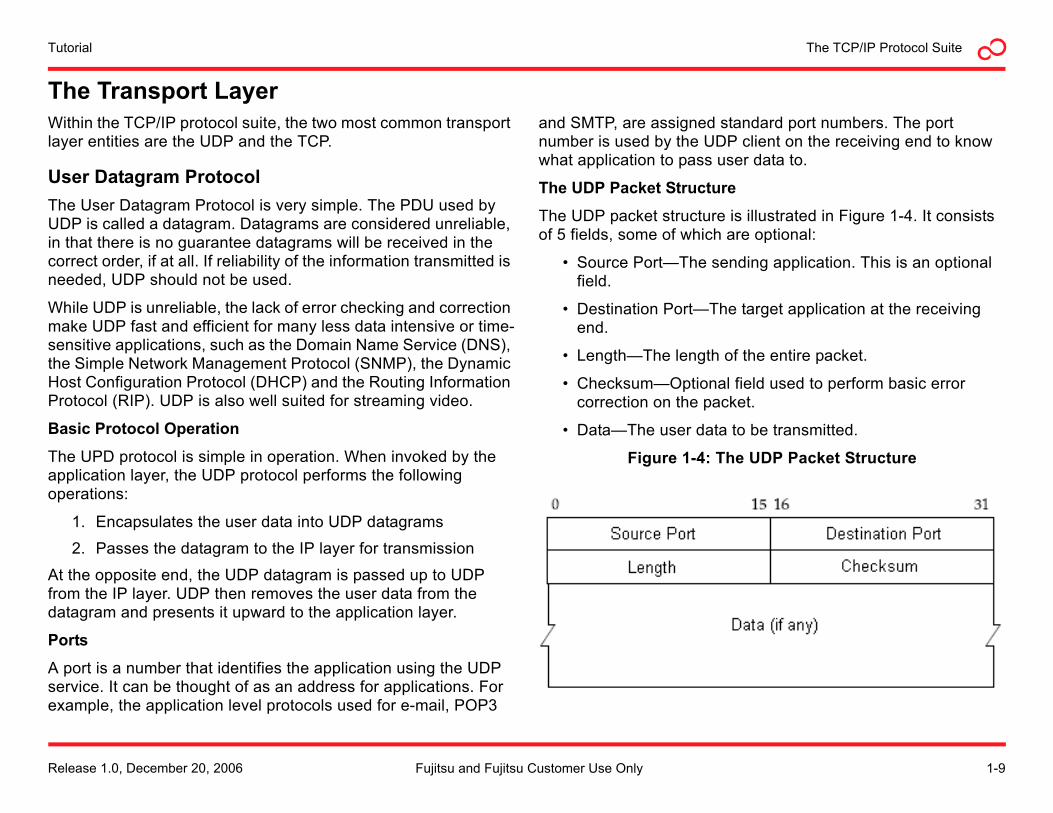
The UDP packet structure is illustrated in Figure 1-4. It consists of 5 fields, some of which are optional:
• Source Port—The sending application. This is an optional field.
• Destination Port—The target application at the receiving end.
• Length—The length of the entire packet.
• Checksum—Optional field used to perform basic error correction on the packet.
• Data—The user data to be transmitted.
Figure 1-4: The UDP Packet Structure
Release 1.0, December 20, 2006 1-9Fujitsu and Fujitsu Customer Use Only
TutorialThe TCP/IP Protocol Suite
Transmission Control ProtocolIn the TCP/IP protocol suite, TCP is the intermediate layer between IP below it, and an application above it. Using TCP, applications on networked hosts can establish reliable connections to one another. The protocol guarantees in-order delivery of data from the sender to the receiver.
Basic Protocol Operation
The Transmission Control Protocol is connection-oriented, meaning user data is not exchanged between TCP peers until a connection is established between the two end points. This connection exists for the duration of the data transmission.
TCP connections have three phases:
1. Connection establishment
2. Data transfer
3. Connection termination
Connection Establishment
To establish a connection, TCP uses a 3-way handshake. Before a client attempts to connect with a server, the server must first bind to a port to open it up for connections. This is called a passive open. Once the passive open is established, a client may initiate an active open. The server then sends an acknowledgement to the client. At this point, both the client and server have received an acknowledgement of the connection.
Data Transfer
A few key features set TCP apart from UDP:
• Error-free data transfer
• Ordered-data transfer
• Retransmission of lost packets
• Discarding of duplicate packets
• Congestion throttling
Error Free Data Transfer
Error-free data transfer is guaranteed by TCP. It does this by calculating a 16-bit checksum over the TCP packet (header and data). At the receiving end, if the checksum does not match the contents of the packet, it is discarded. Because the sending side does not receive an acknowledgement of the discarded packet, it is retransmitted.
Ordered-Data Transfer
Streams of data called segments are used by TCP peers to speak to each other. The segments can be quite large, so TCP breaks up the segments into smaller units of data. These units are encapsulated in the TCP packet that is passed to the IP protocol. Each unit of data is assigned a sequence number, which becomes part of the TCP packet. At the receiving end, the TCP module uses the sequence numbers in the packet to reconstruct the user data in the correct order.
1-10 Release 1.0, December 20, 2006Fujitsu and Fujitsu Customer Use Only
The TCP/IP Protocol SuiteTutorial
Retransmission of Lost Packets
When transmitting large amounts of data, it is not unusual for some information to get lost along the way. In order to guarantee reliable transfer of data, TCP requires an acknowledgement of each packet it sends. This acknowledgement is sent by the TCP module at the receiving host. If an acknowledgement is not received within a specified time period, it will be retransmitted.
Discarding Duplicate Packets
The TCP client retransmits packets that it determines to be lost. The TCP module at the receive side may eventually receive packets that were considered to be lost after the sending side has retransmitted the data. This may result in the receiving end receiving two or more copies of the same packet. The receiving end TCP module uses the unique sequence numbers in the packet to determine if data duplication has occurred and discards any packets it determines to be duplicates.
Congestion Throttling
The final property of TCP is congestion throttling or flow control. The goal is for TCP to be able to send data to the receiving end at the fastest rate possible, without overwhelming it.
When TCP first begins transmitting data to the far end, it sets a timer. The timer determines how long the sender should wait for a packet to be acknowledged before retransmitting it. If all packets are received well before the timer expires, TCP will incrementally increase the transmission speed, until packets begin to become unacknowledged during the time out period. When a significant number of packets have to be retransmitted, TCP slows down the rate at which it sends data to the other end.
Connection Termination
The connection termination phase uses, at most, a four-way handshake, with each side of the connection terminating independently. When an end point wishes to stop its half of the connection, it transmits a special packet with a flag indicating it is finished. The other end acknowledges the flag. A typical connection termination includes this two-phase handshake from both ends of the connection.
TCP Sockets
Transmission Control Protocol is connection-oriented. A virtual connection is first created then maintained through the duration of data transfer. The end points of the connection between TCP peers are called sockets. A socket is identified by a combination of the source host address and port together with the destination host address and port. Arriving TCP data packets are identified as belonging to a specific TCP connection by its socket. From a logical standpoint, TCP peers communicate directly with each other over the socket connection. In reality, reading and writing packets to a socket is how TCP interfaces with the IP layer below it.
Release 1.0, December 20, 2006 1-11Fujitsu and Fujitsu Customer Use Only
TutorialThe TCP/IP Protocol Suite
TCP Packet Structure
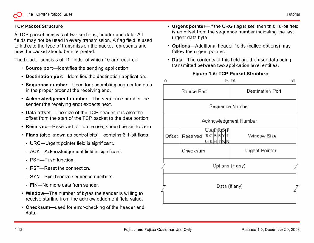
A TCP packet consists of two sections, header and data. All fields may not be used in every transmission. A flag field is used to indicate the type of transmission the packet represents and how the packet should be interpreted.
The header consists of 11 fields, of which 10 are required:
• Source port—Identifies the sending application.
• Destination port—Identifies the destination application.
• Sequence number—Used for assembling segmented data in the proper order at the receiving end.
• Acknowledgement number—The sequence number the sender (the receiving end) expects next.
• Data offset—The size of the TCP header, it is also the offset from the start of the TCP packet to the data portion.
• Reserved—Reserved for future use, should be set to zero.
• Flags (also known as control bits)—contains 6 1-bit flags:
- URG—Urgent pointer field is significant.
- ACK—Acknowledgement field is significant.
- PSH—Push function.
- RST—Reset the connection.
- SYN—Synchronize sequence numbers.
- FIN—No more data from sender.
• Window—The number of bytes the sender is willing to receive starting from the acknowledgement field value.
• Checksum—used for error-checking of the header and data.
• Urgent pointer—If the URG flag is set, then this 16-bit field is an offset from the sequence number indicating the last urgent data byte.
• Options—Additional header fields (called options) may follow the urgent pointer.
• Data—The contents of this field are the user data being transmitted between two application level entities.
Figure 1-5: TCP Packet Structure
1-12 Release 1.0, December 20, 2006Fujitsu and Fujitsu Customer Use Only
The TCP/IP Protocol SuiteTutorial
Applications that use TCP
The following is a list of common applications that directly use the reliable data transfer services provided by TCP:
• File Transfer Protocol (FTP)—Provides a mechanism for moving data files between systems. The FTP client and server programs, as well as most Web browsers, contain an implementation of the FTP protocol.
• HyperText Transfer Protocol (HTTP)—Protocol used to move Web pages across an internet connection. The HTTP protocol is built into Web browsers and Web servers.
• Interactive Mail Access Protocol (IMAP)—Provides clients access to e-mail messages and mailboxes over a network. It is incorporated into e-mail applications.
• Post Office Protocol (POP)—Allows clients to read and remove e-mail residing on a remote server. It is incorporated into e-mail applications.
• Remote Login (Rlogin)—Provides network remote login capability.
• Simple Mail Transfer Protocol (SMTP)—Used to deliver e-mail from one system to another. It is incorporated into e-mail applications.
• Secure Shell (SSH)—Provides remote access to computers while providing encryption of the data.
• Telnet—Provides network terminal, or remote login capability.
Release 1.0, December 20, 2006 1-13Fujitsu and Fujitsu Customer Use Only
TutorialThe TCP/IP Protocol Suite
The Internet LayerThe Internet layer is the third layer in the TCP/IP protocol suite. The Internet layer responds to service requests from the transport layer (typically TCP or UDP) and issues service requests to the network access layer.
The various Internet layer modules provide:
• Translation between logical addresses and physical addresses
• Routing from the source to the destination computer
• Managing traffic problems, such as switching, routing, and controlling the congestion of data packets
• Maintaining the quality of service requested by the transport layer
The transport layer is responsible for application-to-application data delivery. The Internet layer is responsible for source host to destination host packet delivery, whereas the next layer (network access) is responsible for node to node (hop to hop) frame delivery.
1-14 Release 1.0, December 20, 2006Fujitsu and Fujitsu Customer Use Only
The TCP/IP Protocol SuiteTutorial
The Internet ProtocolThe Internet Protocol (IP) is a data-oriented protocol used for communicating data across a network. It is a best effort protocol; it does not guarantee delivery. It also makes no guarantee as to the correctness of the data it transports. Transmission using IP may result in duplicated packets and/or packets out-of-order. All of these contingencies are addressed by an upper layer protocol (For example, TCP) for applications that require reliable delivery.
IP Addressing
The IP peers address each other using IP addresses. An IP address is a logical identifier for a computer or device on a network. The key feature of IP addresses is that they can be routed across networks.
The format of an IP address is a 32-bit numeric address written as four numbers separated by periods, sometimes referred to as a dotted-quad. The range of each number can be from 0 to 255. For example, 2.165.12.230 would be a valid IP address.
The four numbers in an IP address are used to identify a particular network and a host within that network.
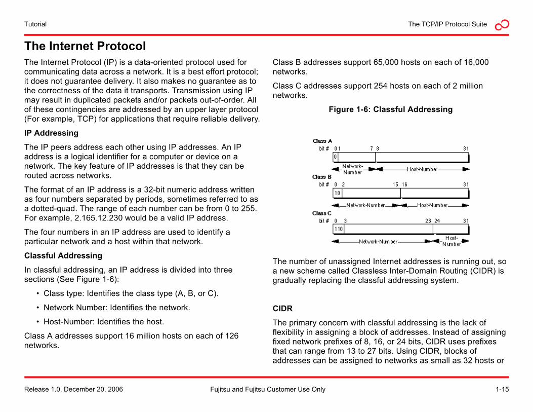
Classful Addressing
In classful addressing, an IP address is divided into three sections (See Figure 1-6):
• Class type: Identifies the class type (A, B, or C).
• Network Number: Identifies the network.
• Host-Number: Identifies the host.
Class A addresses support 16 million hosts on each of 126 networks.
Class B addresses support 65,000 hosts on each of 16,000 networks.
Class C addresses support 254 hosts on each of 2 million networks.
Figure 1-6: Classful Addressing
The number of unassigned Internet addresses is running out, so a new scheme called Classless Inter-Domain Routing (CIDR) is gradually replacing the classful addressing system.
CIDR
The primary concern with classful addressing is the lack of flexibility in assigning a block of addresses. Instead of assigning fixed network prefixes of 8, 16, or 24 bits, CIDR uses prefixes that can range from 13 to 27 bits. Using CIDR, blocks of addresses can be assigned to networks as small as 32 hosts or
Release 1.0, December 20, 2006 1-15Fujitsu and Fujitsu Customer Use Only
TutorialThe TCP/IP Protocol Suite
to those with over 500,000 hosts. This allows address assignments to more closely match the needs of an organization.
A CIDR address looks very similar to a classful IP address. It uses the standard 32-bit dotted-quad notation. The CIDR scheme appends information to the end of the address that specifies how many bits of the address are used for the network prefix. For example, in the CIDR address 106.153.101.15/26, the /26 indicates the first 26 bits are used to identify the unique network, while the remaining bits identify the host on the network.
Private IP Addresses
Network hosts that do not need to have their addresses visible on the public Internet can be assigned private IP address. There are four address ranges that are reserved for private networking use only. These addresses can not be used to route data outside of a private network.
The following are the four IP address ranges reserved for private networks:
• 10.0.0.0—10.255.255.255
• 172.16.0.0—172.31.255.255
• 192.168.0.0—192.168.255.255
• 169.254.0.0—169.254.255.255
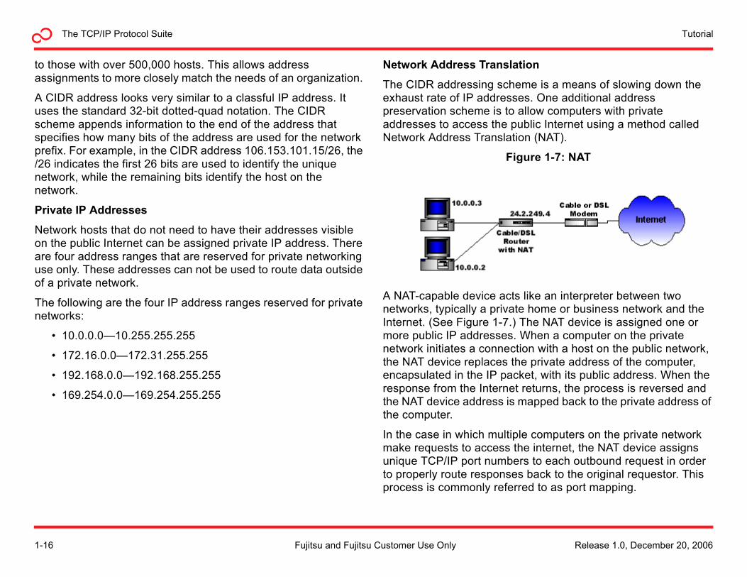
Network Address Translation
The CIDR addressing scheme is a means of slowing down the exhaust rate of IP addresses. One additional address preservation scheme is to allow computers with private addresses to access the public Internet using a method called Network Address Translation (NAT).
Figure 1-7: NAT
A NAT-capable device acts like an interpreter between two networks, typically a private home or business network and the Internet. (See Figure 1-7.) The NAT device is assigned one or more public IP addresses. When a computer on the private network initiates a connection with a host on the public network, the NAT device replaces the private address of the computer, encapsulated in the IP packet, with its public address. When the response from the Internet returns, the process is reversed and the NAT device address is mapped back to the private address of the computer.
In the case in which multiple computers on the private network make requests to access the internet, the NAT device assigns unique TCP/IP port numbers to each outbound request in order to properly route responses back to the original requestor. This process is commonly referred to as port mapping.
1-16 Release 1.0, December 20, 2006Fujitsu and Fujitsu Customer Use Only
The TCP/IP Protocol SuiteTutorial
Fragmentation
Before examining the details of the IP packet structure, it is important to understand the concept of fragmentation. IP exists at the Internet layer. It passes datagrams to the network access for transmission on the network. The various network interfaces impose a limit on the maximum payload size that can be delivered per frame. This limit is called the maximum transmission unit (MTU). If the MTU of the network interface device, such as an Ethernet unit, is smaller than the IP datagram, the IP module must divide the datagram into smaller pieces, called fragments. Each fragment is then put into its a separate IP packet for delivery across the network. Information embedded in the IP header informs the receiving host that the IP datagram is part of a larger block of data and must be reassembled.
The process of fragmenting and reassembling IP datagrams is analogous to the segmentation and reassembly of segments performed by TCP.
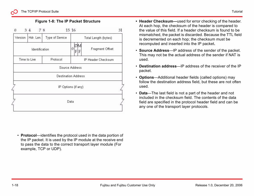
The IP Packet Structure
An IP packet consists of two sections; header and data.
The header consists of 12 mandatory fields and 1 optional field:
• Version—Indicates the IP protocol version being used.
• Internet Header Length (IHL)—Indicates the total size of the IP packet header, so the start of the data portion can be determined.
• Type of Service (TOS)—Defines delay, throughput and reliability requirement of the IP packet.
• Total Length—Indicates the entire packet size, including header and data, in bytes.
• Identification—Used for uniquely identifying fragments of an original IP datagram.
• Flags—Used to control or identify fragments.
• Fragment Offset—Allows a receiver to determine the place of a particular fragment in the original IP datagram, measured in units of 8-byte blocks.
• Time To Live (TTL) The maximum number of hops a packet can traverse between the source and destination hosts. Each packet switch (or router) that a packet crosses decrements the TTL field by one. When the TTL field becomes zero, the packet is no longer forwarded by a packet switch and is discarded. This mechanism prevents packets from being trapped in endless routing loops, clogging up a network.
Release 1.0, December 20, 2006 1-17Fujitsu and Fujitsu Customer Use Only
TutorialThe TCP/IP Protocol Suite
Figure 1-8: The IP Packet Structure
• Protocol—identifies the protocol used in the data portion of the IP packet. It is used by the IP module at the receive end to pass the data to the correct transport layer module (For example, TCP or UDP).
• Header Checksum—used for error checking of the header. At each hop, the checksum of the header is compared to the value of this field. If a header checksum is found to be mismatched, the packet is discarded. Because the TTL field is decremented on each hop; the checksum must be recomputed and inserted into the IP packet.
• Source Address—IP address of the sender of the packet. This may not be the actual address of the sender if NAT is used.
• Destination address—IP address of the receiver of the IP packet.
• Options—Additional header fields (called options) may follow the destination address field, but these are not often used.
• Data—The last field is not a part of the header and not included in the checksum field. The contents of the data field are specified in the protocol header field and can be any one of the transport layer protocols.
1-18 Release 1.0, December 20, 2006Fujitsu and Fujitsu Customer Use Only
The TCP/IP Protocol SuiteTutorial
IP RoutingIf all computers were directly connected on the same physical network, there would be little need for the IP protocol. After all, so far in this description of the protocol, the only job IP has performed has been wrapping the transport layer packet into an IP datagram for transmission by the network level. In reality, an IP datagram sent between two computers on the public network typically passes through many different IP network devices along the way.
It is the ability to route IP packets across different physical networks that is the heart of the Internet.
Routers
The public network, or Internet, is actually a collection of thousands of individual networks, interconnected together. These interconnections form a mesh network, creating millions of paths between the individual computers on the Internet. Routers are dedicated devices that are the interconnection point for the networks of the world.
Routers are responsible for passing IP packets along from the source to the destination, across the various network interconnection points. Each router that an IP packet passes through is referred to as a hop. In general, as the packet traverses the network, a router is only responsible for getting a packet to the next hop along its path.
Routers use the Internet and network layer. Routers need access to the network layer so they can physically receive packets. The network layer then passes the IP datagram up to the router IP layer. The router processes the destination address contained in the IP header and determines which device the send the IP packet on to, typically another router. The transport and user level data is not needed and is not unpacked from the IP
datagram. This allows routers to function very quickly, as they are able to unpack the necessary information from the IP packet using specially designed hardware.
Routing Protocols
Routers are responsible for routing IP packets between a source and destination address. Typically, each router is responsible for only getting a packet to the next router along the path. As such, a router only needs to know the addresses of the routers to which it is directly connected. It also needs to know which connected router should be used for forwarding a packet. When the router examines the IP address of an incoming datagram, it accesses a database or table to determine which router should form the next hop in the path.
Routers use various protocols to communicate with each other in order to set up the tables used to route packets.
Some common routing protocols include:
• Router Information Protocol (RIP)
• Open Shortest Path First (OSPF)
• Interior Gateway Routing Protocol (IGRP)
• Enhanced IGRP (EIGRP)
• Border Gateway Protocol (BGP)
• Intermediate System to Intermediate System (IS-IS)
• Constrained Shortest Path First (CSPF)
While routers operate on packets at the Internet layer, they also use transport layer services such as UDP and TCP to communicate with each other to build routing tables.
Release 1.0, December 20, 2006 1-19Fujitsu and Fujitsu Customer Use Only
TutorialThe TCP/IP Protocol Suite
Address Resolution ProtocolEvery host system, private and public, as well as the routers connecting their networks each have a globally unique physical address. The details of this address will be discussed in the next section. When an IP module requests a datagram be transmitted by the network layer, be it in an end system or an intermediate router, IP must first translate between the IP address and this unique physical address using another Internet layer service, the Address Resolution Protocol (ARP).
Address Resolution Protocol
The Address Resolution Protocol is a method for translating between Internet layer and network layer address. The ARP module in a computer or router maintains a translation table of logical to physical mappings it is aware of, called the ARP cache. If there is not a translation for the address in the table, it will make an ARP broadcast.
Using the Internet and TCP/IP in an example, the basic steps of ARP translation are:
1. ARP checks the local cache to see if it knows the mapping between the IP address and a physical address (the Media Access Control [MAC] address).
2. If there is not a match, ARP broadcasts an ARP request to the local network. The broadcast is received by every computer and router to which the host is connected.
3. If a computer with a matching IP address exists on the local network, it sends its MAC address back. The ARP module adds this translation to the ARP cache for future use.
4. If a router on the local network realizes the requested IP address is outside the local network, it sends back its MAC address, in order for the IP datagram to be forwarded to it.
The same process is used to forward IP datagrams between routers as a packet transverses the network. When a router is designated as the next hop, the MAC address of the router, rather than the receiving computer, is provided as the IP to MAC translation.
1-20 Release 1.0, December 20, 2006Fujitsu and Fujitsu Customer Use Only
The TCP/IP Protocol SuiteTutorial
The Network Access LayerThe network access layer (sometimes referred to as the network interface level or the data link level) defines the procedures for interfacing with the network hardware and accessing the transmission medium. In general, these functions map to the data link and physical layers of the OSI protocol stack.
Within the TCP/IP protocol suite, the network access layer is commonly viewed as a single layer with two sublayers: the media access control (MAC) sublayer and the physical sublayer. The rationale behind the single layer approach reflects that the functionality of both sublayers are often combined with a single device with accompanying driver and firmware. An Ethernet card with its driver is a good example.
The network access layer moves network frames between two hosts. The hosts may be end systems, such as computers or intermediate devices such as routers and switches. The network access layer only moves frames directly between two physically connected devices. All other tasks are the responsibility of the upper levels.
MAC Sublayer
The MAC sublayer prepares data for transmission and obtains access to the transmission medium in shared access systems.
Physical Sublayer
The physical sublayer encodes data and transmits it over the physical network media. It operates with data in the form of bits transmitted over a variety of electrical and optical cables, as well as radio frequencies.
Example Network Layers
Just as IP is independent of the transport layer protocol being used, many different network access layers are defined that carry IP traffic. Some of the more common ones, listed below, are introduced in following sections.
Example network layers:
• Point-to-Point Protocol (PPP)
• Ethernet
• Point-to-Point over Ethernet (PPoE)
• Wireless Fidelity (Wi-Fi)
• Worldwide Interoperability for Microwave Access (WiMAX)
• Frame Relay
• Asynchronous Transfer Mode (ATM)
Release 1.0, December 20, 2006 1-21Fujitsu and Fujitsu Customer Use Only
TutorialThe TCP/IP Protocol Suite
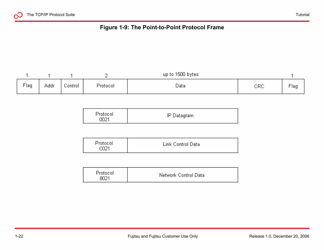
Figure 1-9: The Point-to-Point Protocol Frame
1-22 Release 1.0, December 20, 2006Fujitsu and Fujitsu Customer Use Only
The TCP/IP Protocol SuiteTutorial
Point-to-Point Protocol The Point-to-Point Protocol (PPP) is commonly used to establish a direct physical connection between two nodes. It can connect hosts using serial cable, phone lines, cellular phones, radio links, or fiber optic cables. Most dial-up internet service providers use PPP for customer access to the Internet.
Basic Protocol Operation
The PPP peers exchange three types of frames: Link Control Protocol (LCP), Network Control Protocol (NCP), and data.
In establishing a PPP link, the sending and receiving devices send out LCP packets to determine specific information that the prospective data transmission will require.
The LCP protocol:
• Checks the identity of the linked device and either accepts or rejects the peer device
• Determines the acceptable packet size for transmission
• Searches for errors in configuration
• Terminates the link if requirements exceed the parameters
After the link has been established, PPP provides for an optional authentication phase before proceeding to the NCP phase of the connection. The most common form of authentication uses the Challenge Handshake Authentication Protocol (CHAP).
CHAP
The CHAP module verifies the identify of a peer using a three-way handshake. First, the authenticator sends a challenge message to the peer. The peer responds with a value calculated using a hash function. The information typically hashed is a username/password combination. Lastly, the authenticator
checks the response against the expected hash value. If there is a match, the connection continues, otherwise the link terminates.
After the link is configured by LCP, and optionally authorized using CHAP, the sending device sends NCP frames to select the network layer protocol being used on the link.
Finally, data packets can be sent over the link. The link remains configured for communications until explicit LCP or NCP frames close the link.
PPP Frame Format
The PPP frame contains the following fields:
• Flag Sequence—The binary sequence 01111110 used for frame synchronization.
• Address Field—Contains the binary sequence 11111111. As PPP directly connects two nodes in a network, the address field has no particular meaning.
• Control Field—Contains the binary sequence 00000011.
• Protocol—Two bytes that identify the protocol encapsulated in the data field of the frame:
- 0021— IP. The data field will carry an encapsulated IP datagram.
- C021— LCP. The data field will contain LCP messages.
- 8021 —NCP. The data field will carry NCP messages.
• Data—Carries the datagram for the protocol identified by the protocol field.
• Frame Check Sequence (FCS)—16 bits used for error detection.
Release 1.0, December 20, 2006 1-23Fujitsu and Fujitsu Customer Use Only
TutorialThe TCP/IP Protocol Suite
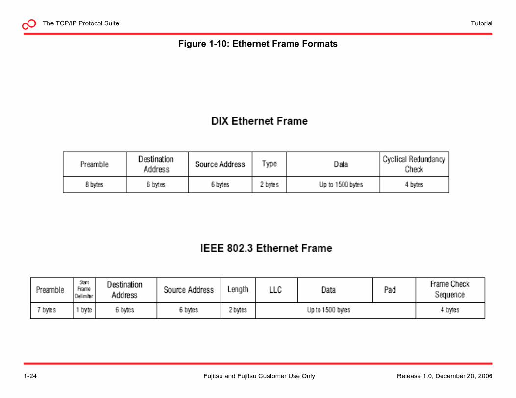
Figure 1-10: Ethernet Frame Formats
1-24 Release 1.0, December 20, 2006Fujitsu and Fujitsu Customer Use Only
The TCP/IP Protocol SuiteTutorial
EthernetEthernet is a family of network access layer frame-based computer networking technologies. As a network access layer standard, it defines:
• A common addressing format
• A means of accessing and sharing the network media
• Several wiring and signaling standards
Ethernet Network Types
There are several types of Ethernet networks in use throughout the world. The most common are:
• Local Area Network (LAN)—Usually confined to a small geographical area such as a building or campus.
• Wide Area Network (WAN)—A collection of LANs that are connected multiple ways using a variety of services.
• Virtual LAN (VLAN)—A group of PCs, servers, and other network resources that behave as if they were connected to a single network segment, even though they may not be.
Ethernet at the MAC Sublayer
At the MAC sublayer, Ethernet peers communicate by exchanging frames, which encapsulate the Internet layer datagram. Ethernet frames are transmitted in the network using globally unique 48-bit physical layer addresses. The MAC address, as it is known, typically comes programmed into an Ethernet device by the manufacturer. A portion of the MAC address is a manufacturer identifier, assigned by the IEEE registration authority. The remaining portion is assigned by the manufacturer. Generally speaking, any device directly connected to an Ethernet LAN must have a MAC address, particularly if it operates above the physical sublayer. This includes computers,
routers, network printers, network attached storage devices, and so forth.
Accessing the Physical Medium
Originally, Ethernet used a single shared coax attached to every device on a network. A scheme known as Carrier Sense Multiple Access with Collision Detection (CSMA/CD) was developed to govern the way the computers on the network shared the channel.
CSMA/CD makes the following assumptions:
1. An Ethernet device will be able to sense if another device is using the medium by detecting a carrier signal.
2. Two Ethernet devices may inadvertently use the medium at the same time, causing frame collisions, requiring a retransmission of the collided frames. An Ethernet device will be able to detect these frame collisions.
When one computer on an Ethernet LAN is required to transmit information, it uses the following algorithm.
Main Procedure
1. Ethernet has a frame ready for transmission.
2. The Ethernet device listens to see if any other device is using the channel. If the medium is not idle, it waits for a period called the inter-frame gap.
3. The Ethernet device starts transmission.
4. Did a frame collision occur? If so, invoke the collision procedure.
5. Frame transmission ends successfully.
Release 1.0, December 20, 2006 1-25Fujitsu and Fujitsu Customer Use Only
TutorialThe TCP/IP Protocol Suite
Collision Detected Procedure
1. Continue transmission until minimum packet time is reached (jam signal) to ensure that all receivers detect the collision.
2. If the maximum number of transmission attempts has been reached, abort the transmission.
3. Calculate and wait a random back-off period.
4. Retry the main procedure.
Modern Ethernet networks still use CSMA/CD to govern access to the transmission medium, at the subnetwork level.
Hubs and Repeaters
Originally, Ethernet LANs were connected in a bus configuration using a single shared cable. For signal degradation and timing reasons, Ethernet networks had a restricted size. Longer networks could be created using a repeater, a device that took the signal from one Ethernet cable and retransmitted it onto another cable. Using a repeater also helped isolate defective Ethernet segments from the rest of the network, as the repeater would repress traffic from the affected segment.
The concept of isolating branches of the network evolved into wiring networks in a star configuration, with a multiport repeater in the center of the star. These multiport repeaters became known as hubs. Because hubs and routers blindly repeat electrical signals without decoding them, they operate at the physical layer of the network.
Bridging and Switching
Using hubs and repeaters, every device on an Ethernet still received every frame placed on the network and had to share the network with all other stations. This placed significant limitations on the number of stations that could be on the network.
The concept of bridging was created to isolate Ethernet segments at the data-link level. The bridge replaced a hub in the star configuration. A bridge examines each packet, with only well-formed (non collided) packets being forwarded to the other segments of the network. Bridges build a table of MAC addresses and learn to forward frames to the segment of the network that contains the destination station, further reducing overall traffic on the network. A switch performs bridging functionality using hardware, providing packet routing forwarding at wire speeds. Because bridges and switches only look at Ethernet frames, they are also considered physical layer devices.
Ethernet Standards
Ethernet was originally developed by the Xerox corporation in the 1970s. In 1980, the Digital Equipment Corporation (DEC), Intel, and Xerox (DIX) released the DIX Ethernet standard. That same year, the Institute of Electrical and Electronics Engineers (IEEE) commissioned a committee to develop open network standards. In 1985, this committee published the portion of the standard pertaining to Ethernet (based on the DIX standard)—IEEE 802.3 Carrier Sense Multiple Access with Collision Detection Access Method and Physical Layer Specifications. Even though the IEEE title does not mention Ethernet, the name had caught on, and IEEE 802.3 was and is referred to as the Ethernet standard.
There are very subtle differences between the DIX Ethernet frame format and the 802.3 frame format. (See Figure 1-10). While the DIX frame is the most commonly deployed, both frames can coexist at the physical level.
1-26 Release 1.0, December 20, 2006Fujitsu and Fujitsu Customer Use Only
The TCP/IP Protocol SuiteTutorial
Ethernet Frames
Ethernet frames consist of 3 portions: header, payload, and trailer.
Header
• Preamble—7-bit sequence used for synchronizing receiver to transmitter. (10Mb/s Ethernet).
• Start Frame Delimiter—8-bit sequence (10101011).
• Destination Address—Destination MAC address.
• Source Address—Source MAC address.
• Type—Indicates the protocol sending the frame (DIX only).
• Length—Indicates the length of data field (number of LLC data bytes) (IEEE 802.3 only).
Payload
• Logical Link Control (LLC)—Governs the assembly of data at the data link (Layer 2) level.
• Data—Payload contained in a field between 46 bytes to just over 1500 bytes in length.
• Pad—0 bits added to the data field if there are fewer than 46 bytes of data in that field.
Trailer
• Cyclical Redundancy Check (CRC)—Detects DIX-only transmission errors.
• Frame Check Sequence (FCS)—Detects transmission errors and provides quality of service at receiving end.
VLAN Tagged Frames
The 802.1q standard defines a 4-byte VLAN tag, which is inserted into a standard Ethernet frame after the source address. The VLAN tag identifies which VLAN the frame should be routed to. It also carries additional information used for priority and routing information. Because adding a VLAN tag adds 4-bytes to the standard Ethernet frame, most 802.1q capable devices remove it from the frame before delivering it to its final destination.
Ethernet Versions
Ethernet has evolved significantly since the original thick-coax 10 Mb/s network of the 1980s. Several different versions of the Ethernet standard are in use today.
Fast Ethernet
IEEE 802.3u is commonly referred to as Fast Ethernet or 100Base-T. Because Fast Ethernet offers a choice of 10 or 100 Mb/s bandwidth, the standard also allows for equipment that can auto negotiate the two speeds. Fast Ethernet can be cabled over either twisted-pair or fiber optic cables.
Gigabit Ethernet
Gigabit Ethernet works much the same way as 10 Mb/s and100 Mb/s Ethernet, only faster. It uses the same frame format, full duplex, and flow control methods. Additionally, it takes advantage of CSMA/CD when in half-duplex mode, and it supports Simple Network Management Protocol (SNMP) tools. Gigabit Ethernet takes advantage of jumbo frames to reduce the frame rate to the end host. Jumbo frames are between 64 and 9215 bytes. Gigabit Ethernet can be transmitted over twisted pair cables or optical fiber.
Release 1.0, December 20, 2006 1-27Fujitsu and Fujitsu Customer Use Only
TutorialThe TCP/IP Protocol Suite
10 Gigabit Ethernet
The operation of 10 Gigabit Ethernet (IEE 802.3ae) is similar to that of lower speed Ethernet networks. It maintains the IEEE 802.3 Ethernet frame size and format which preserves layer 3 and higher protocols. However, 10 Gigabit Ethernet only operates over point-to-point links in full-duplex mode, eliminating the need for CSMA/CD. Additionally, it uses only fiber optical cable at the physical layer.
Gigabit Ethernet defines two physical layer network applications:
• Local Area Network (LAN) PHY—Operates at close to the 10 Gigabit Ethernet rate to maximize throughput over short distances.
• Wide Area Network (WAN) PHY—Supports connections to circuit-switched SONET networks. The WAN PHY application includes a WAN interface sublayer (WIS) for making Ethernet frames recognizable and manageable by the SONET equipment they pass through.
Private Networks
The Metro Ethernet Forum (MEF) is a non profit organization that was chartered to accelerate the worldwide adoption of carrier-class Ethernet networks and services. The MEF has specified two services that replace traditional static permanent virtual circuits with Ethernet virtual circuits:
• ELINE—Point-to-point service that supports scalability, quality of service (QOS) and VLAN tagging.
• ELAN—multipoint-to-multipoint service that allows hosts to be connect and disconnected dynamically.
Ethernet over SONET
Ethernet over SONET (EOS) refers to a set of protocols that pass Ethernet traffic over Synchronous Optical Network (SONET) networks.
Two standardized protocols are used for transmitting EOS:
• Link Access Procedure—SDH (LAPS), also referred to as X.86
• Generic Framing Procedure (GFP)
Point-to-Point Protocol over Ethernet
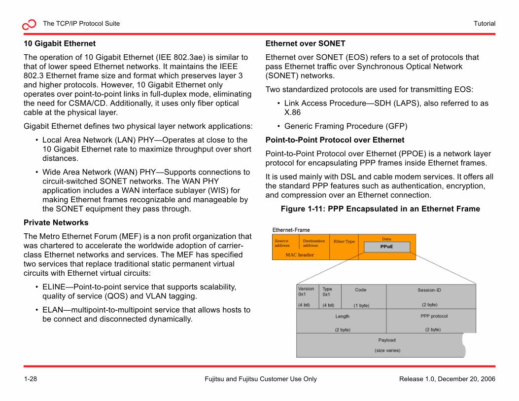
Point-to-Point Protocol over Ethernet (PPOE) is a network layer protocol for encapsulating PPP frames inside Ethernet frames.
It is used mainly with DSL and cable modem services. It offers all the standard PPP features such as authentication, encryption, and compression over an Ethernet connection.
Figure 1-11: PPP Encapsulated in an Ethernet Frame
1-28 Release 1.0, December 20, 2006Fujitsu and Fujitsu Customer Use Only
The TCP/IP Protocol SuiteTutorial
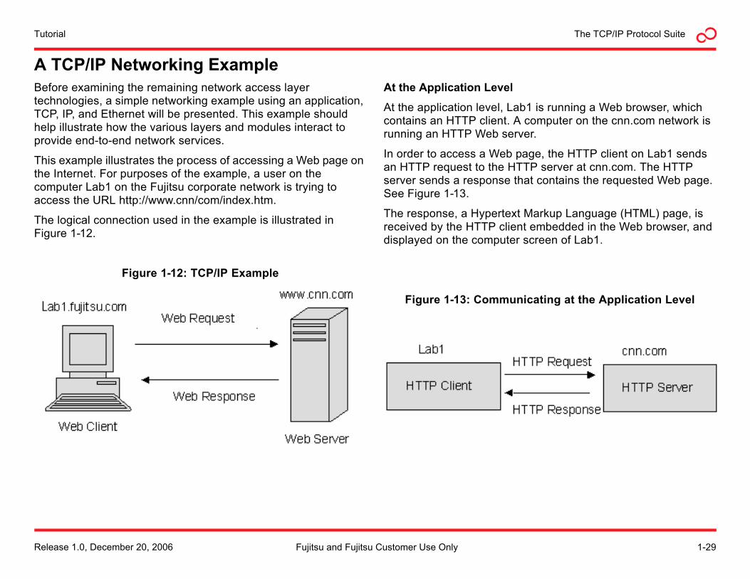
A TCP/IP Networking ExampleBefore examining the remaining network access layer technologies, a simple networking example using an application, TCP, IP, and Ethernet will be presented. This example should help illustrate how the various layers and modules interact to provide end-to-end network services.
This example illustrates the process of accessing a Web page on the Internet. For purposes of the example, a user on the computer Lab1 on the Fujitsu corporate network is trying to access the URL http://www.cnn/com/index.htm.
The logical connection used in the example is illustrated in Figure 1-12.
Figure 1-12: TCP/IP Example
At the Application Level
At the application level, Lab1 is running a Web browser, which contains an HTTP client. A computer on the cnn.com network is running an HTTP Web server.
In order to access a Web page, the HTTP client on Lab1 sends an HTTP request to the HTTP server at cnn.com. The HTTP server sends a response that contains the requested Web page. See Figure 1-13.
The response, a Hypertext Markup Language (HTML) page, is received by the HTTP client embedded in the Web browser, and displayed on the computer screen of Lab1.
Figure 1-13: Communicating at the Application Level
Release 1.0, December 20, 2006 1-29Fujitsu and Fujitsu Customer Use Only
TutorialThe TCP/IP Protocol Suite
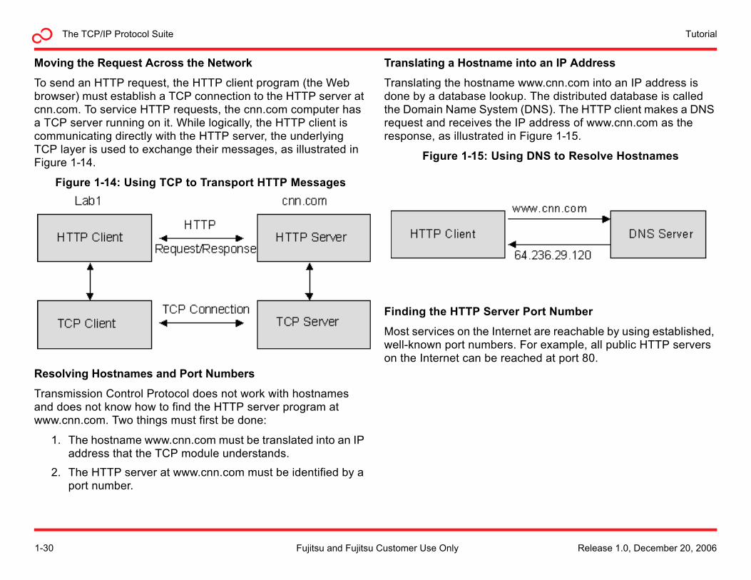
Moving the Request Across the Network
To send an HTTP request, the HTTP client program (the Web browser) must establish a TCP connection to the HTTP server at cnn.com. To service HTTP requests, the cnn.com computer has a TCP server running on it. While logically, the HTTP client is communicating directly with the HTTP server, the underlying TCP layer is used to exchange their messages, as illustrated in Figure 1-14.
Figure 1-14: Using TCP to Transport HTTP Messages
Resolving Hostnames and Port Numbers
Transmission Control Protocol does not work with hostnames and does not know how to find the HTTP server program at www.cnn.com. Two things must first be done:
1. The hostname www.cnn.com must be translated into an IP address that the TCP module understands.
2. The HTTP server at www.cnn.com must be identified by a port number.
Translating a Hostname into an IP Address
Translating the hostname www.cnn.com into an IP address is done by a database lookup. The distributed database is called the Domain Name System (DNS). The HTTP client makes a DNS request and receives the IP address of www.cnn.com as the response, as illustrated in Figure 1-15.
Figure 1-15: Using DNS to Resolve Hostnames
Finding the HTTP Server Port Number
Most services on the Internet are reachable by using established, well-known port numbers. For example, all public HTTP servers on the Internet can be reached at port 80.
1-30 Release 1.0, December 20, 2006Fujitsu and Fujitsu Customer Use Only
The TCP/IP Protocol SuiteTutorial
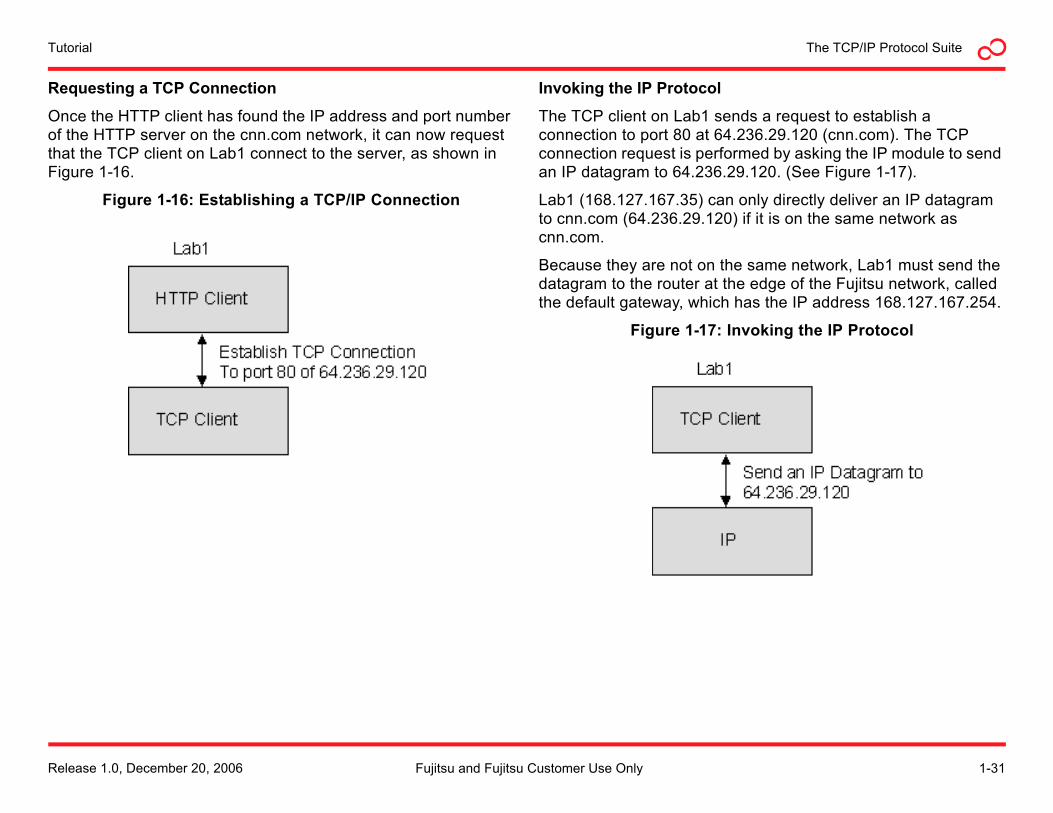
Requesting a TCP Connection
Once the HTTP client has found the IP address and port number of the HTTP server on the cnn.com network, it can now request that the TCP client on Lab1 connect to the server, as shown in Figure 1-16.
Figure 1-16: Establishing a TCP/IP Connection
Invoking the IP Protocol
The TCP client on Lab1 sends a request to establish a connection to port 80 at 64.236.29.120 (cnn.com). The TCP connection request is performed by asking the IP module to send an IP datagram to 64.236.29.120. (See Figure 1-17).
Lab1 (168.127.167.35) can only directly deliver an IP datagram to cnn.com (64.236.29.120) if it is on the same network as cnn.com.
Because they are not on the same network, Lab1 must send the datagram to the router at the edge of the Fujitsu network, called the default gateway, which has the IP address 168.127.167.254.
Figure 1-17: Invoking the IP Protocol
Release 1.0, December 20, 2006 1-31Fujitsu and Fujitsu Customer Use Only
TutorialThe TCP/IP Protocol Suite
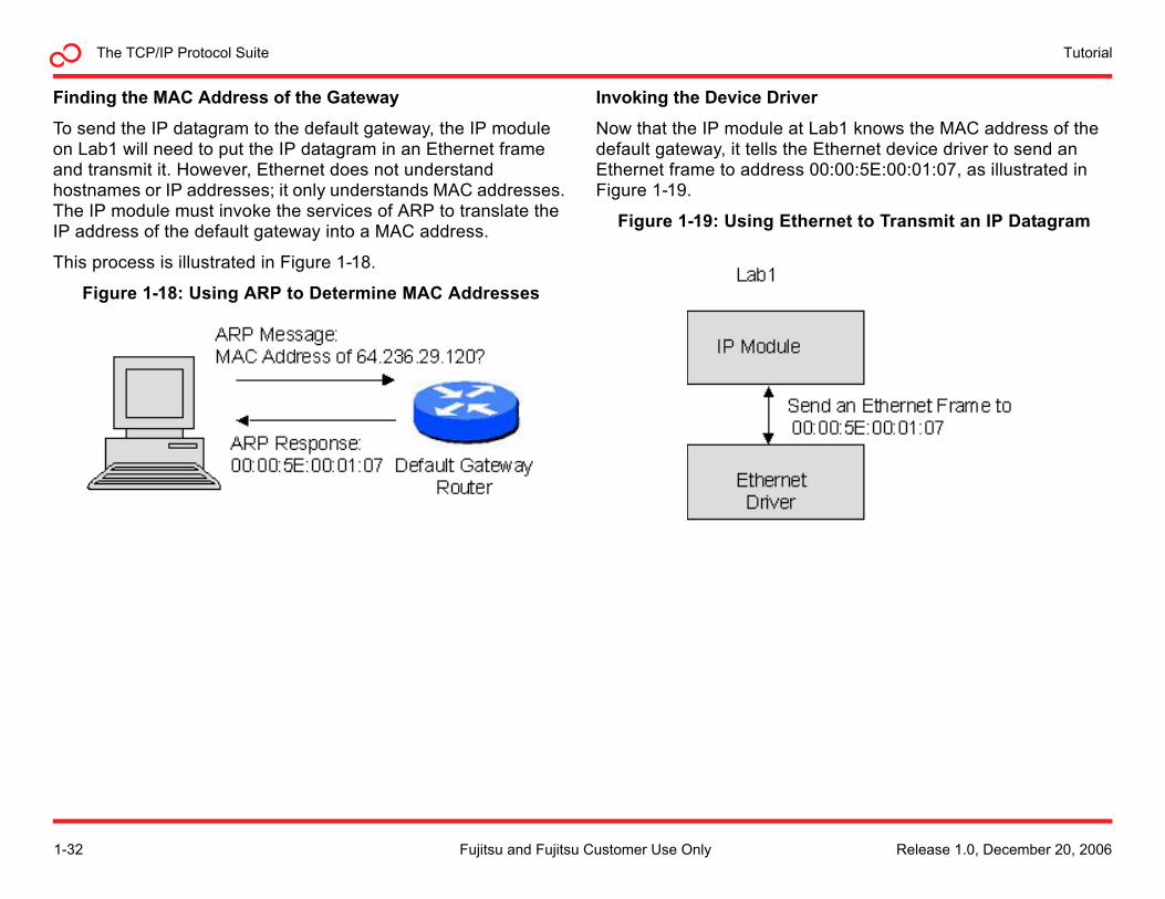
Finding the MAC Address of the Gateway
To send the IP datagram to the default gateway, the IP module on Lab1 will need to put the IP datagram in an Ethernet frame and transmit it. However, Ethernet does not understand hostnames or IP addresses; it only understands MAC addresses. The IP module must invoke the services of ARP to translate the IP address of the default gateway into a MAC address.
This process is illustrated in Figure 1-18.
Figure 1-18: Using ARP to Determine MAC Addresses
Invoking the Device Driver
Now that the IP module at Lab1 knows the MAC address of the default gateway, it tells the Ethernet device driver to send an Ethernet frame to address 00:00:5E:00:01:07, as illustrated in Figure 1-19.
Figure 1-19: Using Ethernet to Transmit an IP Datagram
1-32 Release 1.0, December 20, 2006Fujitsu and Fujitsu Customer Use Only
The TCP/IP Protocol SuiteTutorial
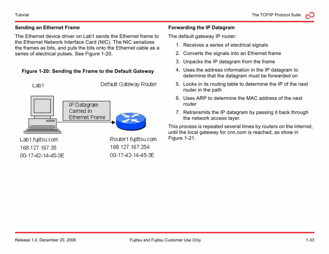
Sending an Ethernet Frame
The Ethernet device driver on Lab1 sends the Ethernet frame to the Ethernet Network Interface Card (NIC). The NIC serializes the frames as bits, and puts the bits onto the Ethernet cable as a series of electrical pulses. See Figure 1-20.
Figure 1-20: Sending the Frame to the Default Gateway
Forwarding the IP Datagram
The default gateway IP router:
1. Receives a series of electrical signals
2. Converts the signals into an Ethernet frame
3. Unpacks the IP datagram from the frame
4. Uses the address information in the IP datagram to determine that the datagram must be forwarded on
5. Looks in its routing table to determine the IP of the next router in the path
6. Uses ARP to determine the MAC address of the next router
7. Retransmits the IP datagram by passing it back through the network access layer.
This process is repeated several times by routers on the Internet, until the local gateway for cnn.com is reached, as show in Figure 1-21.
Release 1.0, December 20, 2006 1-33Fujitsu and Fujitsu Customer Use Only
TutorialThe TCP/IP Protocol Suite
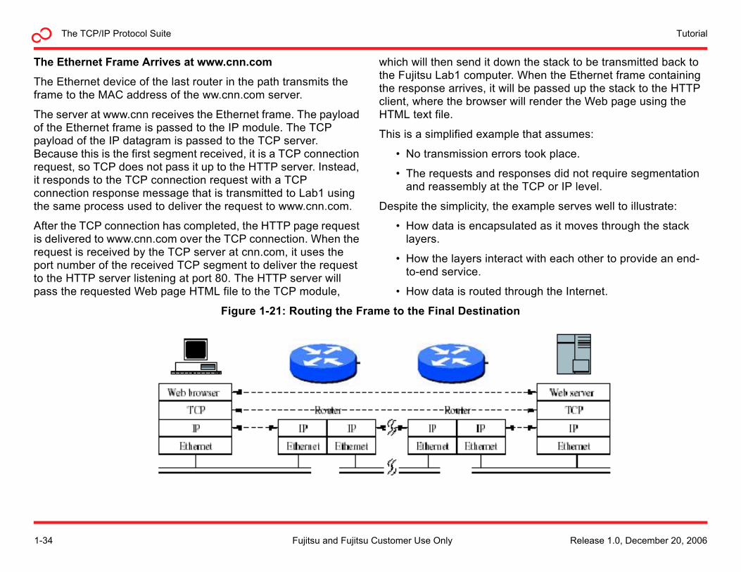
The Ethernet Frame Arrives at www.cnn.com
The Ethernet device of the last router in the path transmits the frame to the MAC address of the ww.cnn.com server.
The server at www.cnn receives the Ethernet frame. The payload of the Ethernet frame is passed to the IP module. The TCP payload of the IP datagram is passed to the TCP server. Because this is the first segment received, it is a TCP connection request, so TCP does not pass it up to the HTTP server. Instead, it responds to the TCP connection request with a TCP connection response message that is transmitted to Lab1 using the same process used to deliver the request to www.cnn.com.
After the TCP connection has completed, the HTTP page request is delivered to www.cnn.com over the TCP connection. When the request is received by the TCP server at cnn.com, it uses the port number of the received TCP segment to deliver the request to the HTTP server listening at port 80. The HTTP server will pass the requested Web page HTML file to the TCP module,
which will then send it down the stack to be transmitted back to the Fujitsu Lab1 computer. When the Ethernet frame containing the response arrives, it will be passed up the stack to the HTTP client, where the browser will render the Web page using the HTML text file.
This is a simplified example that assumes:
• No transmission errors took place.
• The requests and responses did not require segmentation and reassembly at the TCP or IP level.
Despite the simplicity, the example serves well to illustrate:
• How data is encapsulated as it moves through the stack layers.
• How the layers interact with each other to provide an end-to-end service.
• How data is routed through the Internet.
Figure 1-21: Routing the Frame to the Final Destination
1-34 Release 1.0, December 20, 2006Fujitsu and Fujitsu Customer Use Only
The TCP/IP Protocol SuiteTutorial
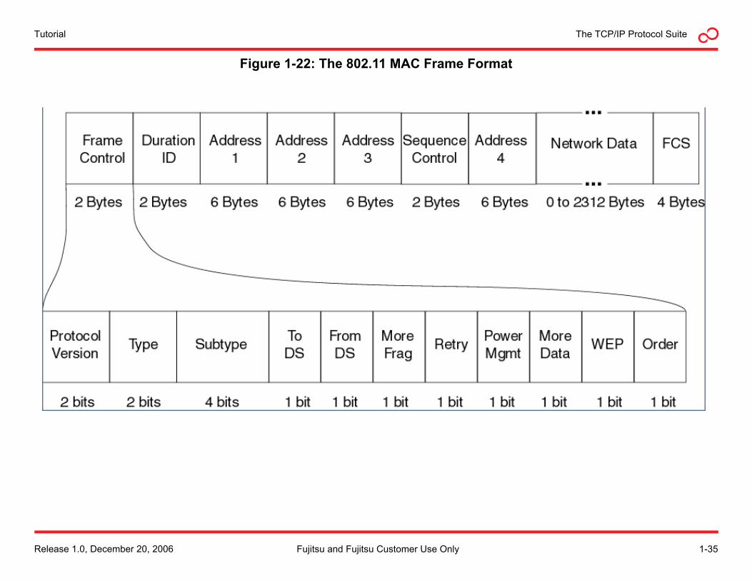
Figure 1-22: The 802.11 MAC Frame Format
Release 1.0, December 20, 2006 1-35Fujitsu and Fujitsu Customer Use Only
TutorialThe TCP/IP Protocol Suite
Wireless FidelityWireless Fidelity, or Wi-Fi, is a brand name licensed by the Wi-Fi Alliance to describe wireless LANS (WLAN) based on the IEEE 802.11 family of specifications. Similar to Ethernet, Wi-Fi exists at the network layer, defining MAC-level frames, as well as physical specifications for transmitting the frames over an radio interface.
Purpose of Wi-Fi
Wi-Fi was developed as a method for mobile devices, such as laptops and personal digital assistants (PDAs), to connect to corporate LANS or the public Internet. Wi-Fi also allows connectivity in peer-to-peer mode, which enables devices to connect directly with each other. In practice, Wi-Fi provides a wireless bridge to Ethernet LANs and the public Internet.
Basic Wi-Fi Operation
A Wi-Fi network contains one or more Access Points (APs). The area in which clients are in range of the radio signal of the APs is commonly called a hotspot. APs are identified by clients by their Service Set Identifier (SSID), which is periodically broadcast by the AP. A client initiates a connection with the AP, which may or may not be accepted depending upon what connection criteria have been set. Various degrees of security and encryption can be used over the wireless connection. Most APs serve as bridges to an Ethernet LAN, converting Ethernet frames to 802.11 frames for transmission over the radio.
Wi-Fi Standards
IEEE 802.11x is actually a family of standards for wireless LANS. The most popular are the a,b,g, and n amendments to the original standard.
• 802.11a—operates in the 5 GHz band with a 54 Mb/s maximum data rate and 25 Mb/s typical data rate.
• 802.11b—operates in the 2.4 GHz band with an 11 Mb/s maximum data rate and 6.5 Mb/s typical data rate.
• 802.11g—operates in the 2.4 GHz band with a 54 Mb/s maximum data rate and 25 Mb/s typical data rate.
• 802.11n (draft)—will operate in the 2.4 or 5 GHz band with a 540 Mb/s maximum data rate and 200 Mb/s typical data rate.
The difference between the maximum data rate and the typical data rate reflects the overhead consumed by the transport, internet, and network layer protocols involved. Wireless networks typically have higher overhead due to the methods used to encode the data for transmission over the air.
1-36 Release 1.0, December 20, 2006Fujitsu and Fujitsu Customer Use Only
The TCP/IP Protocol SuiteTutorial
Wi-Fi Devices
Several types of devices are used in Wi-Fi networks.
Wireless Access Point
A wireless access point (WAP) connects a group of wireless stations to an adjacent wired LAN. In its simplest form, a WAP is similar an Ethernet hub, repackaging Ethernet frames from a wired segment into 802.11 frames for transmission across the wireless interface, and vice versa.
Wireless Routers
A wireless router integrates a WAP with an IP router and an Ethernet switch. The integrated switch connects the integrated WAP and Ethernet router internally, and allows for external wired Ethernet LAN devices to be connected as well as a (usually) single WAN device such as cable modem or DSL modem. A wireless router allows all three devices (mainly the access point and router) to be configured through one central configuration utility, usually through an integrated Web server.
Wireless Ethernet Bridge
A wireless Ethernet bridge connects a wired network to a wireless network. Two wireless bridges may be used to connect two wired networks over a wireless link, which is useful in situations where a wired connection may be unavailable, such as between two separate homes.
Range Extender
A wireless range extender (or wireless repeater) can increase the range of an existing wireless network by being strategically placed in locations where a wireless signal is sufficiently strong and nearby locations that have poor to no signal strength. It receives radio frames and retransmits them unaltered, serving as the wireless version of an Ethernet repeater.
Wireless Access Devices
A wireless access device provides a computing device an 802.11 interface to the wireless network. It serves the same function as an Ethernet card for a computer on a wired network.
Wireless network devices come in many different form factors:
• PCI Cards—Typically plugged into desktop computers
• PCMCIA Cards—Used in laptops
• USB devices—Connected to desktops or laptops
• Compact Flash Cards—Used in PDAs
• SDIO Cards—Used in PDAs
• Built-in chipsets—Common in PDAs, laptops, and some cellphones
Release 1.0, December 20, 2006 1-37Fujitsu and Fujitsu Customer Use Only
TutorialThe TCP/IP Protocol Suite
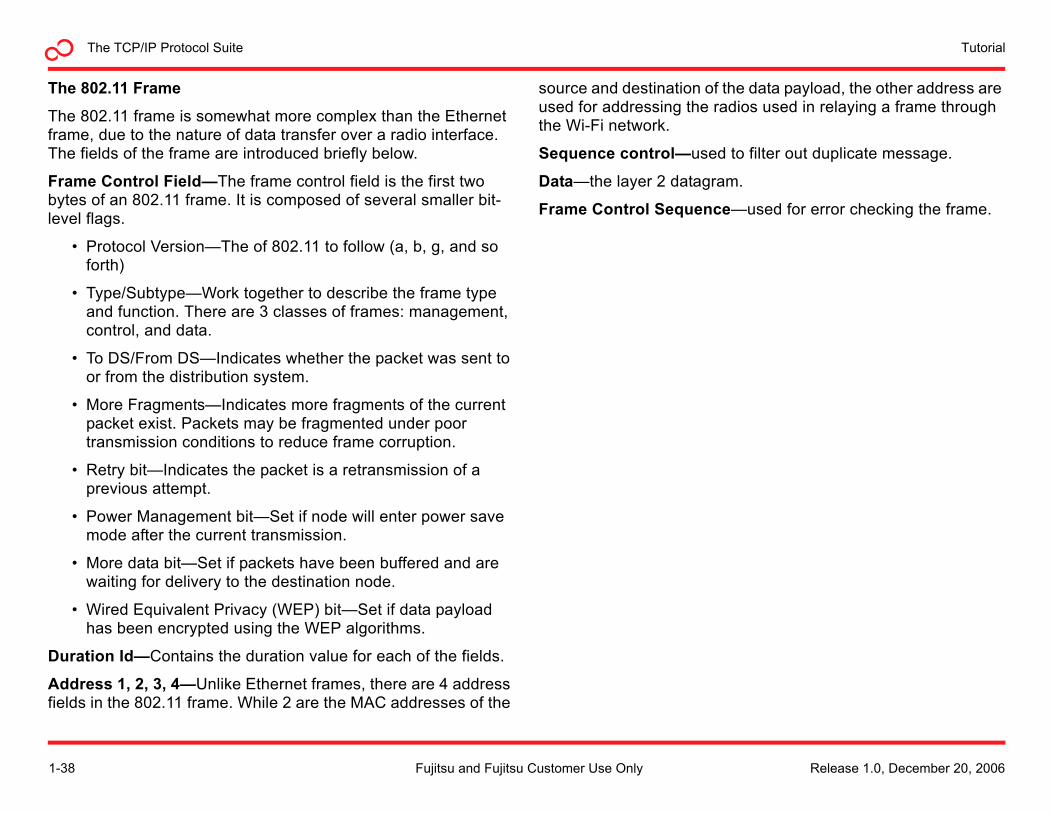
The 802.11 Frame
The 802.11 frame is somewhat more complex than the Ethernet frame, due to the nature of data transfer over a radio interface. The fields of the frame are introduced briefly below.
Frame Control Field—The frame control field is the first two bytes of an 802.11 frame. It is composed of several smaller bit-level flags.
• Protocol Version—The of 802.11 to follow (a, b, g, and so forth)
• Type/Subtype—Work together to describe the frame type and function. There are 3 classes of frames: management, control, and data.
• To DS/From DS—Indicates whether the packet was sent to or from the distribution system.
• More Fragments—Indicates more fragments of the current packet exist. Packets may be fragmented under poor transmission conditions to reduce frame corruption.
• Retry bit—Indicates the packet is a retransmission of a previous attempt.
• Power Management bit—Set if node will enter power save mode after the current transmission.
• More data bit—Set if packets have been buffered and are waiting for delivery to the destination node.
• Wired Equivalent Privacy (WEP) bit—Set if data payload has been encrypted using the WEP algorithms.
Duration Id—Contains the duration value for each of the fields.
Address 1, 2, 3, 4—Unlike Ethernet frames, there are 4 address fields in the 802.11 frame. While 2 are the MAC addresses of the
source and destination of the data payload, the other address are used for addressing the radios used in relaying a frame through the Wi-Fi network.
Sequence control—used to filter out duplicate message.
Data—the layer 2 datagram.
Frame Control Sequence—used for error checking the frame.
1-38 Release 1.0, December 20, 2006Fujitsu and Fujitsu Customer Use Only
The TCP/IP Protocol SuiteTutorial
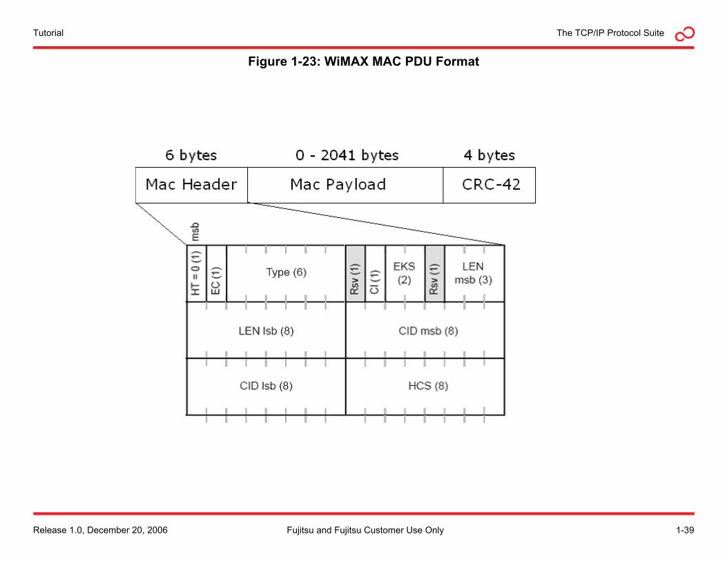
Figure 1-23: WiMAX MAC PDU Format
Release 1.0, December 20, 2006 1-39Fujitsu and Fujitsu Customer Use Only
TutorialThe TCP/IP Protocol Suite
Worldwide Interoperability for Microwave AccessWorldwide Interoperability for Microwave Access, or WiMAX, is a certification name for equipment that conforms to the IEEE 802.16 standards for fixed wireless access systems.
The WiMAX forum is a nonprofit organization formed to promote the adoption of IEEE 802.16 compliant equipment by operators of broadband wireless access systems. The forum describes WiMAX as “a standards-based technology enabling the delivery of last mile wireless broadband access as an alternative to cable and DSL.”
WiMAX Architecture
The 802.16 standards describe a fixed wireless Metropolitan Area Network (MAN). The architecture describes a backbone of base stations connected to a public network. Each of these base stations supports fixed subscriber terminals. These fixed terminals could be WiFI hotspots or individual WiMAX subscriber stations mounted on the rooftops of individual users.
The WiMAX base stations and subscriber terminals operate at the MAC layer and below, providing interoperability with other networking technologies, much as Wi-Fi does.
Currently, WiMAX deployments are focused on providing last mile broadband access to places where DSL and cable infrastructure does not exist. WiMAX can be use to bring broadband directly to end users. Alternatively, WiMAX can be used to compliment Wi-Fi by providing backhaul service to a neighborhood hotspot, with Wi-Fi providing the last hundred feet.
Eventually, WiMAX standards will be extended to offer mobile data services, supporting broadband access to mobile devices as they move from base station to base station, much as cellular providers do today.
Basic WiMAX Operation
WiMAX is similar to Wi-Fi in that both standards provide wireless network access. However, WiMAX is different from Wi-Fi in the way it operates.
WI-Fi networks are contention based. Subscriber stations compete for the attention of an access point in order to transmit data. While this is acceptable for basic Internet access, it is not well suited for applications that require consistent Quality of Service (QoS) such as Voice over IP (VOIP) or Internet-based video services.
Instead, WiMAX uses a scheduling algorithm for the subscriber terminals connected to a base station. Each subscriber station is assigned a specific time slot. The duration and frequency of the time slot is configured on a per-subscriber basis, according to the service level agreement offered to the end user. This provides for the throughput predictability that is essential for VOIP and IPTV.
In the United States, WiMAX operates on licensed frequencies, unlike Wi-Fi. This increases the reliability of the WiMAX network by reducing the possibility of radio interference from other providers. The WiMAX standard defines operation in the 2 to 11 GHz range, with the 2.5, 3.5 and 5.8 Ghz bands being the most deployed at this stage.
WiMAX Protocol
WiMAX operates at the network level of the TCP/IP model. Like Ethernet, WiMAX is divided into MAC and physical sublayers. WiMAX further divides the MAC into 3 sublayers: the convergence sublayer, the common sublayer, and the privacy sublayer.
1-40 Release 1.0, December 20, 2006Fujitsu and Fujitsu Customer Use Only
The TCP/IP Protocol SuiteTutorial
Convergence Sublayer
Like Ethernet and Wi-Fi, WiMAX can be used for carrying native IP datagrams. Additionally, WiMAX can be used for transparently carrying traffic from other networks, such as Ethernet frames or ATM cells. The Convergence Sublayer (CS) is used for preparing the frames from other network types to be carried in the WiMAX MAC layer frame. The two convergence sublayers defined in the 802.16 standard are the ATM CS and the packet CS.
The ATM CS is used for transporting ATM traffic over a WiMAX connection.
The packet CS offers 3 modes:
• IP Specific—Used for carrying IP datagrams directly.
• Ethernet—Used for carrying 802.3 Ethernet frames.
• VLAN Ethernet—Used for carrying 802.1Q VLAN frames.
After data passes through the convergence sublayer, it is passed to the common MAC sublayer.
Common MAC Sublayer
There are two basic types of MAC sublayer PDUs, one for subscriber terminals to request bandwidth from the base station, and another for carrying user data.
The fields of the common MAC PDU are defined below.
• HT—Header type, distinguishes between a data PDU header and a bandwidth request header.
• EC—Encryption control, indicates if the PDU payload has been encrypted.
• Type—Indicates the special payload types present in the message payload.
• CI—CRC Indicator, indicates if CRC has been appended to the packet.
• EKS—Encryption key sequence, index of the key used to encrypt the payload.
• LEN—Length, number of bytes in the PDU, including the header and CRC, if present.
• CID—Connection Identifier.
• HCS—Header Check Sequence, used for detecting errors in the header.
• Payload—The datagram.
• CRC—Used for error checking.
Beyond the basic PDU structure, there are additional headers defined for bandwidth request and other special message types. The additional subheaders can be inserted into a PDU right after the generic header.
Release 1.0, December 20, 2006 1-41Fujitsu and Fujitsu Customer Use Only
TutorialThe TCP/IP Protocol Suite
MAC Privacy Sublayer
The MAC privacy sublayer provides authentication, secure key exchange, and data encryption.
Physical Sublayer
The physical sublayer is responsible for framing the MAC PDU for transmission, media access, and slot allocation.
The 802.16 standard supports both Time Division Duplex (TDD) and Frequency Division Duplex (FDD) operation. With the TDD technique, the system transmits and receives within the same channel, assigning time slices for transmit and receive mode. The FDD technique requires two separate radio spectrums for the uplink and downlink channels.
WiMAX uses 256 carrier Orthogonal Frequency Division Multiplexing (256 OFDM) for modulating data for transmission on the radio carrier. Based on Frequency Division Multiplexing (FDM), OFDM is technology that uses multiple frequencies to simultaneously transmit multiple signals in parallel. Each signal has a frequency range (subcarrier), which is then modulated by data.
WiMAX supports the following modulation techniques;
• BPSK
• QPSK
• 16QAM
• 64QAM
1-42 Release 1.0, December 20, 2006Fujitsu and Fujitsu Customer Use Only
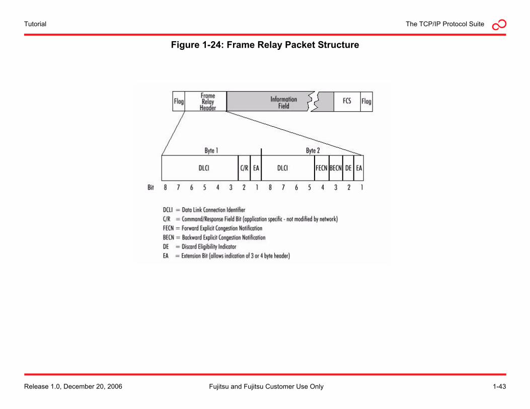
The TCP/IP Protocol SuiteTutorial
Figure 1-24: Frame Relay Packet Structure
Release 1.0, December 20, 2006 1-43Fujitsu and Fujitsu Customer Use Only
TutorialThe TCP/IP Protocol Suite
Frame RelayFrame Relay is a high-performance network access layer protocol designed for Wide Area Networks (WANs). It is often used as an efficient method for transmitting voice and data between remote LANS over a service provider WAN. This allows for intermittent traffic between remote LANS without the expense of a dedicated wired connection in between.
Basic Description
Similar to Ethernet, Frame Relay divides data into frames. Error correction and retransmission is handled completely by upper layer protocols, speeding the transmission, or relay, of frames through the WAN.
Frames traveling through a Frame Relay network can be prioritized. This allows service providers to offer various levels of service quality. For example, packetized voice or video traffic would typically require a higher priority through the network than sending e-mail or Web browsing.
Service Quality
The service quality assigned to a Frame Relay connection is called the Committed Information Rate (CIR). Circuits can also be assigned a burstable bandwidth rate, called the Extended Information Rate (EIR). A service provider, as part of a Service Level Agreement (SLA), guarantees that the connection will always support the CIR, and the EIR, as well, provided bandwidth is available. Frames sent that exceed the CIR are marked as Discard Eligible (DE), which means they can be dropped if congestion occurs on the network. Frames sent in excess of the EIR are dropped immediately.
Connections over a Frame Relay network are typically assigned a traffic descriptor, a collection of statistical properties about the connection. Traffic descriptors describe the CIR, as well as the
committed burst size and excess burst size. The network determines whether to accept a new connection request, based on the relation of the requested traffic descriptor and the residual capacity of the network.
Once the network has established a connection, the edge node of the Frame Relay network must monitor the traffic flow of the connection to ensure that the actual usage of network resources does not exceed this specification.
Frame Relay Equipment
Devices that are connected to a Frame Relay WAN fall into two basic categories:
• Data Terminating Equipment (DTE)
• Data Circuit-terminating Equipment (DCE)
A DTE is the connection point between a LAN and the Frame Relay WAN. A DTE is considered to belong to the LAN. It could be a computer, router, bridge or other network device.
A DCE is part of the Frame Relay network. The DCEs are the equipment, typically packet switches, that route and transmit the frames through the WAN.
1-44 Release 1.0, December 20, 2006Fujitsu and Fujitsu Customer Use Only
The TCP/IP Protocol SuiteTutorial
Virtual Circuits
Frame Relay is a connection-oriented protocol. DTEs are connected by a logical path through the provider DCE devices, called a Virtual Circuit (VC). Each VC is identified by a Data-link Connection Identifier (DLCI). A number of VCs can be multiplexed into a single physical circuit for transmission across the network. This capability can often reduce the equipment and network complexity required to connect multiple DTE devices.
Frame Relay VCs fall into two categories:
• Switched Virtual Circuits (SVCs)—VCs that are only switched on when data needs to be transmitted between DTEs.
• Permanent Virtual Circuits (PVCs)—VCs that are always turned on, whether data is being transmitted or not.
Local Management Interface
The Local Management Interface (LMI) is a set of enhancements to the basic Frame Relay specification. It offers a number of extensions for managing complex networks. Frame Relay LMI extensions include global addressing, virtual circuit status messages, and multicasting. LMI frames have a frame format that differs from the standard frame relay PDU, and are not addressed in this tutorial.
Frame Format
The Frame Relay PDU format is relatively simple (see Figure 1-24), and is composed of the following fields:
• Flag—A fixed binary pattern used to identify the start of frames.
• Address—The address field is made up of the following:
- DLCI—Identifies the virtual connection the frame will use through the WAN.
- Extended Address (EA)—For future use, to allow longer DLCIs to be used.
- C/R—Not currently defined.
- Congestion Control—3 bits that control Frame Relay congestion notification mechanisms.
• Data—Variable length field that transports the higher layer PDU through the WAN.
• Frame Check Sequence—Used for error checking; computed by the source and checked by the destination.
Release 1.0, December 20, 2006 1-45Fujitsu and Fujitsu Customer Use Only
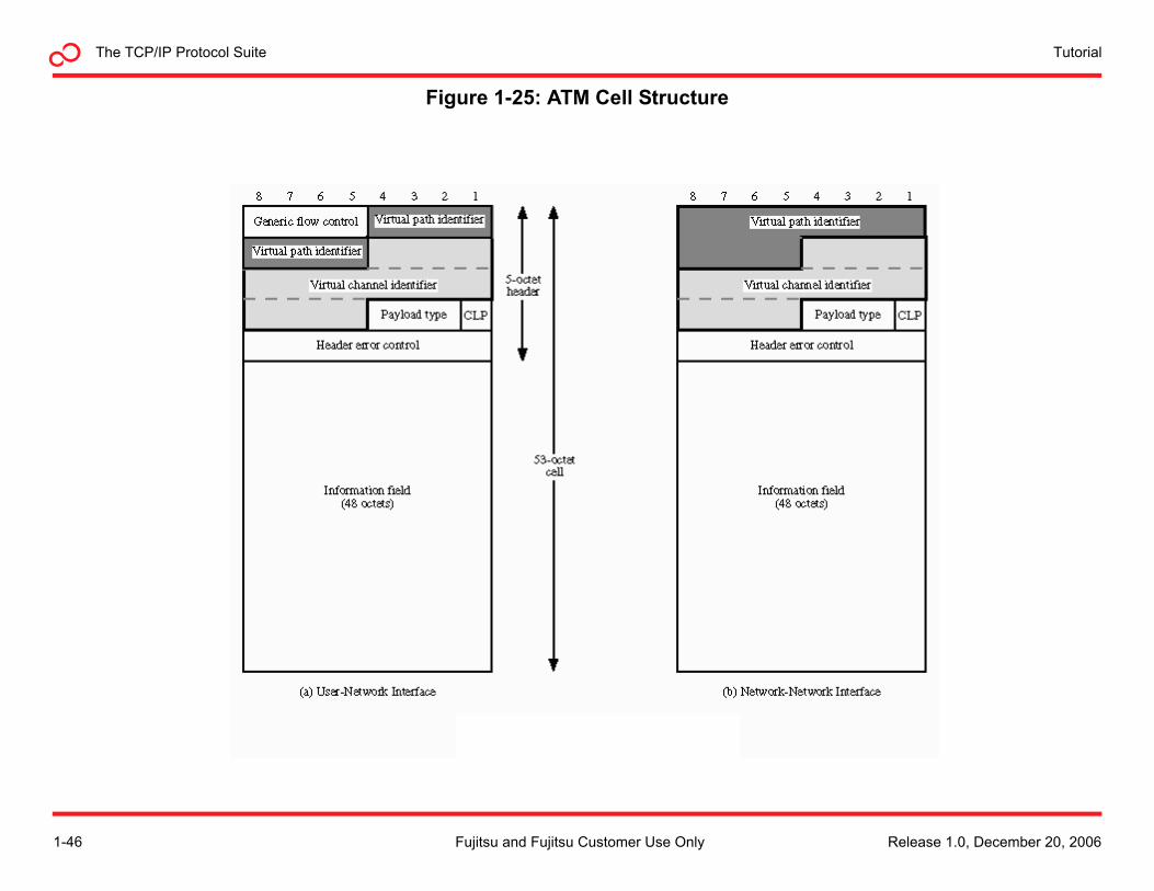
TutorialThe TCP/IP Protocol Suite
Figure 1-25: ATM Cell Structure
1-46 Release 1.0, December 20, 2006Fujitsu and Fujitsu Customer Use Only
The TCP/IP Protocol SuiteTutorial
Asynchronous Transfer ModeAsynchronous Transfer Mode (ATM) is a network access level switching and multiplexing technology that employs small, fixed-length frames, called cells, to quickly and efficiently move all types of traffic. The small cell size makes ATM adaptable to many types of information, such as data, voice, and video.
Virtual Circuits
Asynchronous Transfer Mode is a channel-based transport layer. A Virtual Circuit (VC) is the basic channel unit in ATM, and carries a single stream of cells between two users. VCs that are delivered together can be bundled into a Virtual Path (VP). All cells in a VP are routed the same way through the network, without the need to route individual cells. A VP can specify an end-to-end path across an ATM network. An ATM network can also use VPs for bundling VCs between ATM switches in the ATM core, even if the VCs are not headed to the same end destinations.
The VCs can be set up statically as Permanent Virtual Circuits (PVCs) or dynamically as Switched Virtual Circuits (SVCs).
Traffic Engineering
A key ATM concept is that of the traffic contract. When an ATM circuit is set up, each switch is informed of the traffic class of the connection.
Traffic contracts are part of the mechanism by which ATM ensures Quality of Service (QOS). There are four basic QOS types that each have a set of parameters describing the connection:
• CBR—Constant Bit Rate: A constant Peak Cell Rate (PCR) is specified.
• VBR—Variable Bit Rate: Average cell rate is specified.
• ABR—Available Bit Rate: A minimum guaranteed rate is specified.
• UBR—Unspecified Bit Rate: Traffic is allocated using remaining transmission capacity.
Most traffic classes also introduce the concept of Cell Delay Variation Tolerance (CDVT), which defines the clumping of cells in time. The CDVT is similar to the concept of jitter in Ethernet networks.
Traffic contracts are usually maintained by the use of traffic shaping, which is a combination of queuing and marking of cells, and enforced by traffic policing.
Release 1.0, December 20, 2006 1-47Fujitsu and Fujitsu Customer Use Only
TutorialThe TCP/IP Protocol Suite
Traffic Shaping
Traffic shaping is usually done at the entry point to an ATM network and attempts to ensure that the cell flow will meet its traffic contract.
Traffic Policing
To maintain network performance it is possible to police VCs against their traffic contracts. If a VC is exceeding its traffic contract, the network can either drop the cells or mark the cells as discardable further down the line. Basic policing works on a cell by cell basis, but this is suboptimal for encapsulated packet traffic (as discarding a single cell will invalidate the whole packet). As a result, schemes such as Partial Packet Discard (PPD) and Early Packet Discard (EPD) have been created that will discard a whole series of cells until the next frame starts.
The ATM Protocol
The ATM protocol layer model consists of 4 layers and 3 planes. The layers are closely interrelated, but each layer addresses a specific set of functions. The physical layer and ATM layer can be compared with the physical layer of the OSI reference model.
ATM Adaptation Layer
The ATM Adaptation Layer (AAL) is the top ATM layer in the proto-col stack. This layer interacts with higher layers to get such cus-tomer information as voice, video, and data into and out of the payload portion of a 53-byte ATM cell.
AAL functions are divided between two sublayers:
• Segmentation and Reassembly (SAR)
• Convergence Sublayer (CS)
The SAR sublayer takes a continuous bit stream of customer data, slices it up, and puts it into small ATM cells. At the other end of the network, the SAR sublayer unwraps the ATM cells and recon-structs the bit stream.
The CS sublayer provides different classes of service (A, B, C, D, or X) and performs a variety of tasks that are dependent on the AAL type in which the CS resides. The AAL types are described in the following paragraphs.
AAL Type 1
AAL Type 1 (AAL1) is class A service that is connection oriented and capable of handling CBR traffic such as voice and video conferences. AAL1 requires exact timing between source and destination, so it needs to travel over a synchronous network (for example, SONET or SDH).
1-48 Release 1.0, December 20, 2006Fujitsu and Fujitsu Customer Use Only
The TCP/IP Protocol SuiteTutorial
AAL Type 2
Class B traffic is supported by AAL Type 2 (AAL2). Similar to AAL1, AAL2 is also connection-oriented; however, AAL2 can have a variable bit rate in real time and does not require end-to-end timing. It is well suited for compressed audio and video and travels at a high priority through the ATM network.
AAL Type 3/4
After AAL types 3 and 4 were developed, it was determined they were so similar that they were combined to form AAL3/4. This combined type supports class C or class D non—real-time, variable bit rate traffic that requires no timing.
AAL Type 5
The primary AAL for data, both connection-oriented and connectionless is AAL Type 5 (AAL5). It is known as the Simple and Efficient Layer (SEAL) because nothing extra is appended to the CS-PDU that goes into the 48-octet payload. AAL5 supports class C and class X traffic, including LAN Emulation (LANE) and IP, with unspecified or available bit rates.
ATM Layer
The ATM layer performs many critical functions essential to the exchange of end-to-end communications:
• Adds the 5-byte header to the 48 byte payload received from the ATM adaptation layer
• Multiplexes all the cells from various connections, preparing a single-cell stream for the physical layer
• Puts in idle cells, if needed, as fillers for synchronous transmission systems (for example, SDH or SONET)
Physical Layer
The physical layer of the ATM protocol has four functions:
• Converts cells to a bit stream
• Controls transmission and receipt of bits on the physical medium
• Tracks ATM cell boundaries
• Packages cells into frame types that fit the physical medium
The physical layer is divided into two sublayers that perform these functions:
• Physical Medium Dependent (PMD)—Syncs the bits and gets them to or from the correct medium, down to the correct cable and connector types
• Transmission Convergence (TC)—Performs error checking, maintains cell boundaries and synchronization and packages the cells for the particular physical medium.
Release 1.0, December 20, 2006 1-49Fujitsu and Fujitsu Customer Use Only
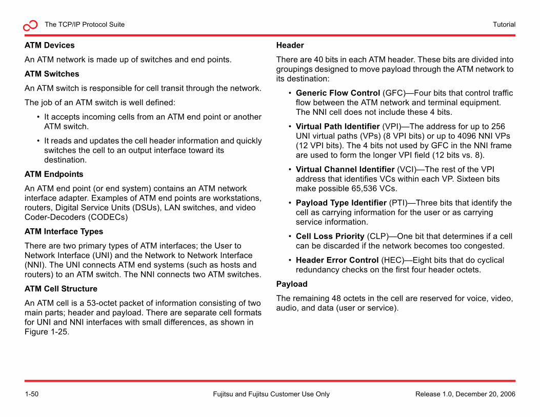
TutorialThe TCP/IP Protocol Suite
ATM Devices
An ATM network is made up of switches and end points.
ATM Switches
An ATM switch is responsible for cell transit through the network.
The job of an ATM switch is well defined:
• It accepts incoming cells from an ATM end point or another ATM switch.
• It reads and updates the cell header information and quickly switches the cell to an output interface toward its destination.
ATM Endpoints
An ATM end point (or end system) contains an ATM network interface adapter. Examples of ATM end points are workstations, routers, Digital Service Units (DSUs), LAN switches, and video Coder-Decoders (CODECs)
ATM Interface Types
There are two primary types of ATM interfaces; the User to Network Interface (UNI) and the Network to Network Interface (NNI). The UNI connects ATM end systems (such as hosts and routers) to an ATM switch. The NNI connects two ATM switches.
ATM Cell Structure
An ATM cell is a 53-octet packet of information consisting of two main parts; header and payload. There are separate cell formats for UNI and NNI interfaces with small differences, as shown in Figure 1-25.
Header
There are 40 bits in each ATM header. These bits are divided into groupings designed to move payload through the ATM network to its destination:
• Generic Flow Control (GFC)—Four bits that control traffic flow between the ATM network and terminal equipment. The NNI cell does not include these 4 bits.
• Virtual Path Identifier (VPI)—The address for up to 256 UNI virtual paths (VPs) (8 VPI bits) or up to 4096 NNI VPs (12 VPI bits). The 4 bits not used by GFC in the NNI frame are used to form the longer VPI field (12 bits vs. 8).
• Virtual Channel Identifier (VCI)—The rest of the VPI address that identifies VCs within each VP. Sixteen bits make possible 65,536 VCs.
• Payload Type Identifier (PTI)—Three bits that identify the cell as carrying information for the user or as carrying service information.
• Cell Loss Priority (CLP)—One bit that determines if a cell can be discarded if the network becomes too congested.
• Header Error Control (HEC)—Eight bits that do cyclical redundancy checks on the first four header octets.
Payload
The remaining 48 octets in the cell are reserved for voice, video, audio, and data (user or service).
1-50 Release 1.0, December 20, 2006Fujitsu and Fujitsu Customer Use Only
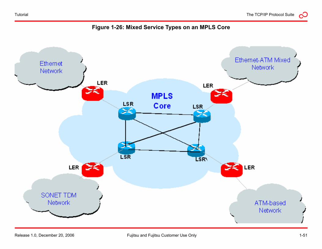
The TCP/IP Protocol SuiteTutorial
Figure 1-26: Mixed Service Types on an MPLS Core
Release 1.0, December 20, 2006 1-51Fujitsu and Fujitsu Customer Use Only
TutorialThe TCP/IP Protocol Suite
Multiprotocol Label Switching Multiprotocol Label Switching (MPLS) is a data-carrying mechanism capable of emulating properties of a circuit-switched network over a packet-switched network. MPLS operates at a layer that is generally considered to lie between the traditional definitions of layer 2 and layer 3, and thus is often referred to as a layer 2.5 protocol. It was designed to provide a unified data-carrying service for both circuit-based clients and packet-switching clients which provide a datagram service model. It can be used to carry many different kinds of traffic, including IP packets, as well as native ATM, SONET, and Ethernet frames.
MPLS has the capability to displace ATM and Frame Relay networks in service-provider backbones and some large enterprise private WANs, while providing backward compatibility with existing networks.
Background
A number of different WAN technologies were previously deployed with essentially identical goals, such as Frame Relay and ATM. MPLS takes up where Frame Relay and ATM leave off, borrowing what works well from those technologies, while leaving behind concepts that have become outdated.
For example, MPLS recognizes that ATM cells are not needed in the core of modern networks, as modern optical networks are capable of transmitting full-length 1500-byte IP packets without the types of delays that the 53 byte cells of ATM were designed to prevent.
At the same time, it attempts to preserve the traffic engineering and out-of-band control that made Frame Relay and ATM attractive for deployment in large scale networks.
The MPLS Core
Multiprotocol Label Switching is designed to make up the core of a service provider (or large corporate) WAN. At the edge of the MPLS core are Label Edge Routers (LERs). LERs prepare packets for entry, or ingress, into the MPLS core and exit, or egress, from the core. Within the core are Label Switch Routers (LSRs), which switch packets on their journey through the core. (See Figure 1-26). The specific responsibilities of LERs and LSRs are described in the next section.
Before examining how MPLS works, it is important to define some basic concepts used in MPLS networks.
Forward Equivalency Class (FEC)—A FEC describes a set of packets with similar or identical characteristics that may be transported together through a network it the same way. Quality of service parameters are often used for defining FECs.
Label—Used to identify a direct path between two individual nodes in an MPLS network.
Label Information Base (LIB)—A table maintained by LSRs and LERs that maps FECs to labels.
Label Switched Path (LSP)—A series of labels that indicates the end-to-end path of a packet through an MPLS network. It is sometimes referred to as an MPLS tunnel.
1-52 Release 1.0, December 20, 2006Fujitsu and Fujitsu Customer Use Only
The TCP/IP Protocol SuiteTutorial
How MPLS Works
Packets traversing an MPLS network pass through three basic phases:
• Ingress into the MPLS core
• Label switching between LSRs in the core
• Egress from the MPLS Core
Each of these stages will be discussed in the following sections.
Ingress into the MPLS core
When a packet enters the MPLS network, it is assigned an FEC. Packets are only assigned to an FEC one time, as they enter the network. The FEC will determine the path the packet takes through the network.
The LER uses the LIB to map the FEC to a label. The LER adds the label to the packet, and forwards it to the next hop.
Label Switching at the LSR
When a packet arrives at an LSR, the LSR uses the label value to determine the path the packet should take to the next hop. The label value is then removed and replaced with a new one, which the next LSR in the path will use to forward the packet along the LSP.
Egress from the Network
When a packet reaches the egress point of the network, the last label is removed and the packet passes out of the network in the same format that it was passed in.
Pseudowires
One of the compelling features of MPLS is pseudowires, the emulation of a native service over a packet switched network. The native service may be ATM, Frame Relay, Ethernet, or SONET/SDH.
As MPLS networks can be deployed over Ethernet, Frame Relay, or ATM equipment, pseudowires over MPLS provide for very flexible network deployments.
Using a combination of pseudowires and MPLS, service providers can offer new services over existing legacy networks, or conversely, legacy services over new network technologies.
Release 1.0, December 20, 2006 1-53Fujitsu and Fujitsu Customer Use Only
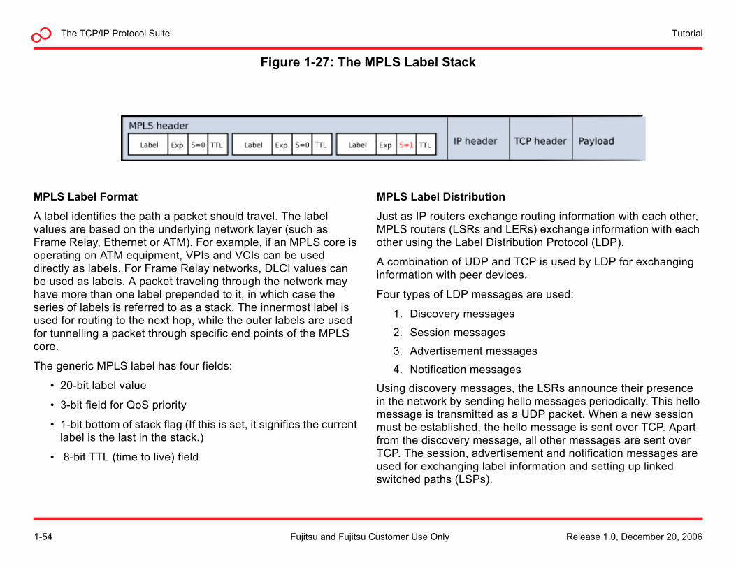
TutorialThe TCP/IP Protocol Suite
Figure 1-27: The MPLS Label Stack
MPLS Label Format
A label identifies the path a packet should travel. The label values are based on the underlying network layer (such as Frame Relay, Ethernet or ATM). For example, if an MPLS core is operating on ATM equipment, VPIs and VCIs can be used directly as labels. For Frame Relay networks, DLCI values can be used as labels. A packet traveling through the network may have more than one label prepended to it, in which case the series of labels is referred to as a stack. The innermost label is used for routing to the next hop, while the outer labels are used for tunnelling a packet through specific end points of the MPLS core.
The generic MPLS label has four fields:
• 20-bit label value
• 3-bit field for QoS priority
• 1-bit bottom of stack flag (If this is set, it signifies the current label is the last in the stack.)
• 8-bit TTL (time to live) field
MPLS Label Distribution
Just as IP routers exchange routing information with each other, MPLS routers (LSRs and LERs) exchange information with each other using the Label Distribution Protocol (LDP).
A combination of UDP and TCP is used by LDP for exchanging information with peer devices.
Four types of LDP messages are used:
1. Discovery messages
2. Session messages
3. Advertisement messages
4. Notification messages
Using discovery messages, the LSRs announce their presence in the network by sending hello messages periodically. This hello message is transmitted as a UDP packet. When a new session must be established, the hello message is sent over TCP. Apart from the discovery message, all other messages are sent over TCP. The session, advertisement and notification messages are used for exchanging label information and setting up linked switched paths (LSPs).
1-54 Release 1.0, December 20, 2006Fujitsu and Fujitsu Customer Use Only
The TCP/IP Protocol SuiteTutorial
Tutorial ReviewInstructions
Please read the questions below and mark the correct answer.
1. How many protocol layers are in the OSI Networking Model?
a. 4
b. 5
c. 7
d. 10
2. The four layers of the TCP/IP protocol suite are:
a. application, presentation, session and physical
b. application, presentation, session and transport
c. transport, network, data link and physical
d. application, transport, internet and network access
3. The process of including data from an upper level protocol into a lower level protocol is called:
a. packetizing
b. wrapping
c. encapsulation
d. sequencing
4. A packet that is not transported reliably is called a:
a. segment
b. datagram
c. cell
d. Frame
5. The two most common transport layer protocols are:
a. TCP and UDP
b. HTTP and FTP
c. TCP and IP
d. Ethernet and Wi-Fi
6. The PDU used by UDP is called a:
a. datagram
b. frame
c. segment
d. message
7. Which of the following is not a feature of TCP:
a. error-free data transfer
b. ordered data transfer
c. congestion throttling
d. routing of TCP segments
Release 1.0, December 20, 2006 1-55Fujitsu and Fujitsu Customer Use Only
TutorialThe TCP/IP Protocol Suite
8. The end points of TCP connections are called:
a. ports
b. sockets
c. hosts
d. MAC addresses
9. 201.230.112.45/24 is an example of:
a. a MAC address
b. a Class A IP address
c. a CIDR classless IP address
d. a TCP socket
10. Which is not an approach used to preserve IP addresses:
a. assignment of private IP addresses
b. use of CIDR addressing
c. network address translation (NAT)
d. use of classful IP addressing
11. Which of the following would be a valid value for the destination field in the IP packet structure?
a. 11.123.12.45
b. www.google.com
c. 01:02:E3:67:89:F5
d. port 80
12. Routing of data through the Internet is done based on:
a. the destination port number in the TCP packet
b. the destination IP address in the IP datagram
c. the destination MAC address in the Ethernet frame
d. the hostname of the destination
13. The Point-to-Point Protocol is a(an) ___________ layer protocol.
a. application
b. transport
c. network access
d. session
14. Fast Ethernet refers to __________ Ethernet.
a. 10 Mb/s
b. 100 Mb/s
c. 1000 Mb/s
d. 10 Gb/s
15. A group of PCs, servers and other network resources that behave as if they are connected to a single network segment is called a __________.
a. LAN
b. MAN
c. WAN
d. VLAN
1-56 Release 1.0, December 20, 2006Fujitsu and Fujitsu Customer Use Only
The TCP/IP Protocol SuiteTutorial
16. Ethernet peers communicate with each other based on:
a. port numbers
b. IP addresses
c. sockets
d. MAC addresses
17. Ethernet peers exchange __________ of data.
a. segments
b. packets
c. frames
d. datagrams
18. Data takes the following path between a user and the internet:
a. HTTP, TCP, IP, Ethernet
b. TCP, HTTP, IP, Ethernet
c. Ethernet, TCP, IP, HTTP
d. HTTP, UDP, IP, Ethernet
19. Translating a hostname into an IP address is performed by:
a. Address Resolution Protocol (ARP)
b. Domain Name Service (DNS)
c. Network Address Translation (NAT)
d. Media Access Control (MAC)
20. Which uniquely identifies a device on a network?
a. a TCP socket
b. a hostname
c. an IP address
d. a MAC address
21. The area around a Wi-Fi access point is called a:
a. cell site
b. Wireless Area Network (WAN)
c. hotspot
d. fresnel zone
22. WiMax is a name given to wireless networks that conform to the _____ family of standards:
a. 802.3
b. 802.11
c. 802.16
d. 802.20
23. Frame Relay is a ______ technology.
a. LAN
b. MAN
c. WAN
d. PAN
Release 1.0, December 20, 2006 1-57Fujitsu and Fujitsu Customer Use Only
TutorialThe TCP/IP Protocol Suite
24. An ATM cell consists of _________.
a. 48 bytes
b. 53 bytes
c. 801 bytes
d. 1500 bytes
25. The MPLS protocol operates at:
a. layer 3
b. layer 2.5
c. layer 2
d. layer 1
The answers to the review questions are listed on the next page.
1-58 Release 1.0, December 20, 2006Fujitsu and Fujitsu Customer Use Only
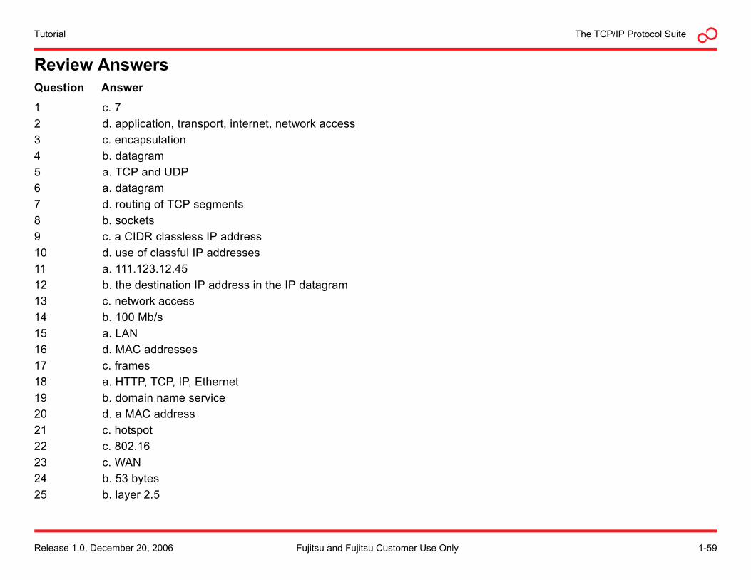
The TCP/IP Protocol SuiteTutorial
Review AnswersQuestion Answer
1 c. 72 d. application, transport, internet, network access3 c. encapsulation4 b. datagram5 a. TCP and UDP6 a. datagram7 d. routing of TCP segments8 b. sockets9 c. a CIDR classless IP address10 d. use of classful IP addresses11 a. 111.123.12.4512 b. the destination IP address in the IP datagram13 c. network access14 b. 100 Mb/s15 a. LAN16 d. MAC addresses17 c. frames18 a. HTTP, TCP, IP, Ethernet19 b. domain name service20 d. a MAC address21 c. hotspot22 c. 802.1623 c. WAN24 b. 53 bytes25 b. layer 2.5
Release 1.0, December 20, 2006 1-59Fujitsu and Fujitsu Customer Use Only
TutorialThe TCP/IP Protocol Suite
1-60 Release 1.0, December 20, 2006Fujitsu and Fujitsu Customer Use Only

Reference
Glossary
TCP/IP Protocol Suite TutorialGlossary
A through B
AAL ATM adaptation layer ANSI American national standards institute
ABR Available bit rate AP Access point
ACK Acknowledgement APC ATM process or controller
ACSE Association control service element API Application programming interface
ADM Add-drop multiplexer APS Automatic protection switch
ADM ATM direct mapped ARP Address resolution protocol
AII Attachment individual identifier ASCII American standard code for information interchange
AIM America online instant messenger ATM Asynchronous transfer mode
AMI Alternate mark inversion AVCR Available cell rate
BCP Bridge control protocol BITS Building integrated timing supply
BER Basic encoding rules BNC British naval/nut connector
BER Bit error rate BPDU Bridge protocol data unit
BGP Border gateway protocol BPSK Binary phase shift keying
Bit Binary digit BT Burst tolerance
R-2 Release 1.0, December 20, 2006Fujitsu and Fujitsu Customer Use Only
GlossaryTCP/IP Protocol Suite Tutorial
C
CAC Connection admission control CLR Cell loss ratio
CAN Campus area network CMF Client management frame
CBR Constant bit rate CMIP Common management information protocol
CDV Cell delay variation CO Central office
CDVT CDV tolerance CORBA Common object request broker architecture
CE Circuit emulation CoS Class of service
CER Cell error ratio CPE Customer premises equipment
CES Circuit emulation services CPU Central processing unit
CHAP Challenge-handshake authentication protocol CRC Cyclical redundancy check
cHEC Core header error check CS Convergence sublayer
CIDR Classless inter-domain routing CSMA/CD Carrier sense multiple access with collision detection
CIR Committed information rate CSPF Constrained shortest path first
CLEC Competitive local exchange carrier CTD Cell transfer delay
CLI Command line interface CTS Clear to send
CLNP Connectionless network protocol CVID Customer VLAN ID
CLP Cell loss priority CWDM Coarse wavelength division multiplexing
Release 1.0, December 20, 2006 R-3Fujitsu and Fujitsu Customer Use Only
TCP/IP Protocol Suite TutorialGlossary
D through E
DA Destination address DS Digital signal
DCD Data carrier detect DSL Digital subscriber line
DCE Data communications equipment DSLAM DSL access multiplexer
DE Discard eligible DSR Data set ready
DEC Digital equipment corporation DTE Data terminal equipment
DHCP Dynamic host configuration protocol DTR Data terminal ready
DIX Digital, Intel, Xerox DWDM Dense wavelength division multiplexing
DLCI Data link connection identifier DXI Data exchange interface
DNS Domain name service
EBCDIC Extended binary coded decimal interchange code EOF End of frame
EEPROM Electronically erasable programmable read-only memory EOS Ethernet over SONET
EFM Ethernet in the first mile EOW Ethernet over wavelengths
EGP Exterior gateway protocol ES End system
EIGRP Enhanced interior gateway protocol ESD Electrostatic discharge
EIR Excess information rate ESF Extended superframe
ELAN Ethernet LAN ESM Extended synchronization module
ELINE Ethernet line
EMI Electromagnetic interference
R-4 Release 1.0, December 20, 2006Fujitsu and Fujitsu Customer Use Only
GlossaryTCP/IP Protocol Suite Tutorial
F through H
FAST Fujitsu assistance FE Fairness eligible
FC Fibre channel FEC Forward equivalence class
FCS Frame check sequence FNC Fujitsu Network Communications Inc.
FCSC FCS error FOCIS Fujitsu online customer information system
FDD Frequency division duplex FR Frame relay
FDDI Fiber distributed data interface FTAC Fujitsu technical assistance center
FDM Frequency division multiplexing FTP File transfer protocol
Gb/s Gigabits per second GigE Gigabit Ethernet
GCRA Generic cell rate algorithm GLAN Gigabit LAN
GFC Generic flow control GUI Graphical user interface
GFP Generic framing procedure GVRP GARP VLAN registration protocol
GHz Gigahertz
HDLC High-level data link control HTTP HyperText transfer protocol
HEC Header error control Hz Hertz
HSSI High-speed serial interface
Release 1.0, December 20, 2006 R-5Fujitsu and Fujitsu Customer Use Only
TCP/IP Protocol Suite TutorialGlossary
I through L
IAM Initial address message IP Internet protocol
IC Integrated circuit IPG Interpacket gap
IDU Interface data unit IRC Internet relay chat
IEEE Institute of electrical and electronics engineers ISDN Integrated services digital network
IETF Internet engineering task force IS-IS Intermediate system to intermediate system
IF Interface ISO International organization of standards
IGP Interior gateway protocol ISP Internet service provider
IMA Inverse multiplexing for ATM ITU International telecommunication union
IMAP Internet message access protocol
kb/s kilobits per second km kilometer
LAN Local area network LIB Label information base
LANE LAN emulation LLC Logical link control
LANG LAN group LMI Local management interface
LAP Link access procedure LSA Link state advertisement
LAPS Link access procedure SDH LSAP Link service access point
LCN Local communication network LSDB Link state database
LCP Link control protocol LSM Loss of synchronization messages
LDP Label distribution protocol LSP Label switched path
LER Label edge router LSR Label switched router
R-6 Release 1.0, December 20, 2006Fujitsu and Fujitsu Customer Use Only
GlossaryTCP/IP Protocol Suite Tutorial
M through O
MAC Media access control MIME Multipurpose internet mail extensions
MAN Metropolitan area network MMF Multimode fiber
MB Megabyte MPEG Motion picture experts group
Mb/s Megabits per second MPLS Multiple protocol label switching
MCR Minimum cell rate ms millisecond
MEF Metro Ethernet forum MTU Maximum transmission unit
MIB Management information base
NAT Network address translation NMS Network management system
NCP Network control protocol NNI Network-to-network interface
NEI Network edge interface nrt-VBR Non—real-time variable bit rate
NIC Network interface card nrt-VFR Non—real-time variable frame rate
NLP Network layer protocol NTP Network time protocol
NMI Network management interfaces
OFDM Orthogonal frequency division multiplexing OSI Open systems interconnect
OH Overhead OSPF Open shortest path first
OOB Out of band OSPF-TE Open shortest path first—traffic engineering
OS Operating system
Release 1.0, December 20, 2006 R-7Fujitsu and Fujitsu Customer Use Only
TCP/IP Protocol Suite TutorialGlossary
P through R
PCR Peak cell rate PMD Physical medium dependent
pdf portable document file PNNI Private network to network interface
PDU Protocol data unit POP Post office protocol
PIR Peak information rate POS Packet over SONET
PLCP Physical layer convergence protocol PPP Point-to-point protocol
PHY Physical layer interface PPPoE PPP over Ethernet
PLI PDU length indicator PVC Permanent virtual connection
PM Physical medium PWE3 Pseudowire edge to edge
QAM Quadrature amplitude modulation QoS Quality of service
RAM Random-access memory RTMP Routing table maintenance protocol
RIP Routing information protocol rt-VBR Real-time—variable bit rate
ROM Read-only memory rt-VFR real-time—variable frame rate
RSVP-TE Reservation protocol—traffic engineering Rx Receive
R-8 Release 1.0, December 20, 2006Fujitsu and Fujitsu Customer Use Only
GlossaryTCP/IP Protocol Suite Tutorial
S through T
SA Source address SONET Synchronous optical network
SAL SONET adaptation layer SPF Shortest path first
SAN Storage area network SRP Selective retransmission protocol
SAR Segmentation and reassembly SSH Secure shell
SCR Sustainable cell rate SSID Service set identifier
SDH Synchronous digital hierarchy STP Spanning tree protocol
SDU Service data unit STS Synchronous transport signal
SHTTP Secure hypertext transfer protocol SU Service unit
SMTP Simple mail transfer protocol SVC Switched virtual connection
SLA Service level agreement SVLAN Stackable virtual local area network
SNMP Simple network management protocol
TAC Technical assistance center TFTP Trivial file transfer protocol
TC Transmission convergence TIB Technical information bulletin
TCP Transmission control protocol TLS Transparent LAN service
TCP/IP Transmission control protocol/internet protocol TLV Time, length, value
TDD Time division duplex TMN Telecommunication management network
TDM Time division multiplexing TTL Time-to-live
TE Traffic engineering Tx Transmit
Release 1.0, December 20, 2006 R-9Fujitsu and Fujitsu Customer Use Only
TCP/IP Protocol Suite TutorialGlossary
U through Z
UBR Unspecified bit rate UPI User payload identifier
UDP User datagram protocol URL Universal resource locator
UNI User network interface UTP Unshielded twisted pair
VBR Variable bit rate VPC VP connection
VC Virtual circuit VPI VP identifier
VCI Virtual channel identifier VPLS Virtual private LAN service
VLAN Virtual LAN VPN Virtual private network
VP Virtual path
W Watt Wi-Fi Wireless fidelity
WAN Wide area network WiMAX Worldwide interoperability for microwave access
WDM Wavelength division multiplexing WRED Weighted random early detection
R-10 Release 1.0, December 20, 2006Fujitsu and Fujitsu Customer Use Only