Embed Size (px)
Citation preview
6/10/2003 – J.J. HogenbirkVLVnT Wavelenght Multipexing 1EFNI HK
Wavelength Multiplexing
Design a MAN* like fiber network for high data transmission rates. The network is partial below sea level and difficult to install and to maintain.
Such a fiber network demands an optimized minimum of cables, connections anda minimum of active (electronic) components c.q. modules. (simplicity)
What to achieve: High data ratesReliability (Low failure rates)Decrease of power needsLong-term stabilityMaintainabilityLow volume mechanicsOpenness (easy to provide)adorable Costs
Conclusions
*Metropolitan Area Network
The Target
6/10/2003 – J.J. HogenbirkVLVnT Wavelenght Multipexing 2EFNI HK
Wavelength Multiplexing
Increase the bit rate (transfer 10 Mbps to 100 Mbps etc.)
SDM space domain multiplexing (parallel cabling)
FDM frequency domain multiplexing
(O)TDM time domain multiplexing (data share time slots)
WDM wave length division multiplexing
Methods to increase data rateson one carrier

6/10/2003 – J.J. HogenbirkVLVnT Wavelenght Multipexing 3EFNI HK
Wavelength Multiplexing
Bit rateOC-12 622 Mbps STS-12/STM4
OC-48 2488 Mbps STS-48/STM-16
OC-3 1.55 Mbps
OC-192 9953 Mbps
SONET/SDH* original optical transport of TDM data
OC-3 1.55 Mbps STS-3/STM-1
* Synchronous Optical NETwork/Synchronous Digital Hierarchy** Optical Carrier
Ethernet switch
1GbE100M Ethernet
100M Ethernet
Bit rate
TELCO (telephone)
DS0 64 KbpsDS1 1.544 MbpsDS2 6.312 MbpsDS3 44.736 Mbps
**
(OC-768 40 Gbps)
TDM/FDM
mux
mux
6/10/2003 – J.J. HogenbirkVLVnT Wavelenght Multipexing 4EFNI HK
Wavelength Multiplexing
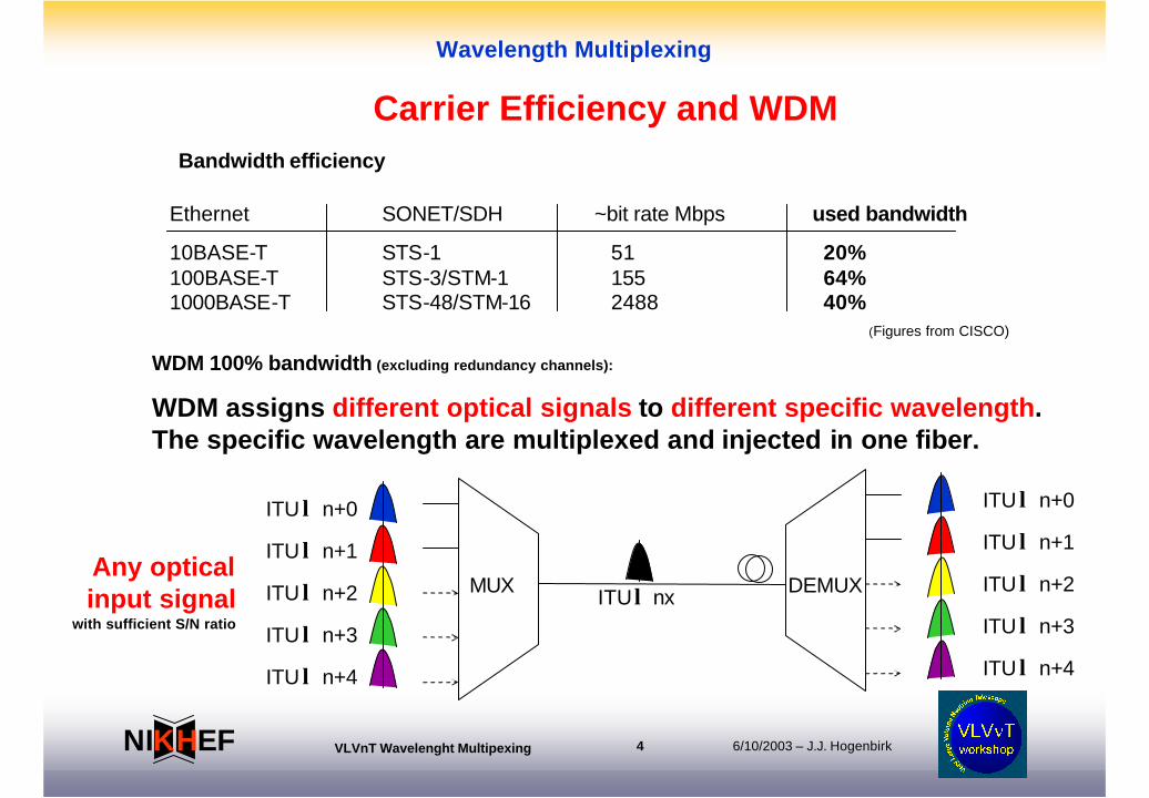
Ethernet SONET/SDH ~bit rate Mbps used bandwidth
10BASE-T STS-1 51 20%100BASE-T STS-3/STM-1 155 64%1000BASE-T STS-48/STM-16 2488 40%
Bandwidth efficiency
WDM 100% bandwidth (excluding redundancy channels):
WDM assigns different optical signals to different specific wavelength.The specific wavelength are multiplexed and injected in one fiber.
(Figures from CISCO)
Any opticalinput signal
with sufficient S/N ratio
MUX DEMUX
ITU n+0 λ
ITU n+1 λ
ITU n+3 λ
ITU n+4 λ
ITU n+2 λ
ITU n+0 λ
ITU n+1 λ
ITU n+3 λ
ITU n+4 λ
ITU n+2 λITU nxλ
Carrier Efficiency and WDM
6/10/2003 – J.J. HogenbirkVLVnT Wavelenght Multipexing 5EFNI HK
Wavelength Multiplexing
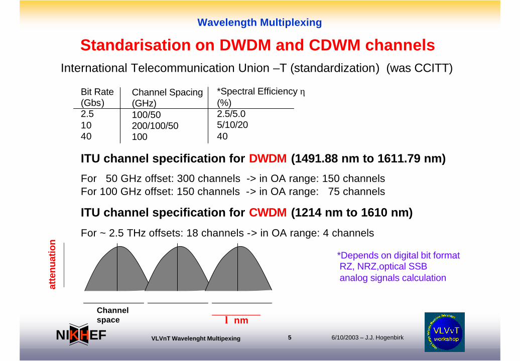
ITU channel specification for DWDM (1491.88 nm to 1611.79 nm)
For 50 GHz offset: 300 channels -> in OA range: 150 channelsFor 100 GHz offset: 150 channels -> in OA range: 75 channels
ITU channel specification for CWDM (1214 nm to 1610 nm)
For ~ 2.5 THz offsets: 18 channels -> in OA range: 4 channels
Bit Rate(Gbs)2.51040
Channel Spacing(GHz)100/50200/100/50100
*Spectral Efficiency η(%)2.5/5.05/10/2040
*Depends on digital bit format RZ, NRZ,optical SSBanalog signals calculation
Channel space λ nm
atte
nuat
ion
Standarisation on DWDM and CDWM channelsInternational Telecommunication Union –T (standardization) (was CCITT)

6/10/2003 – J.J. HogenbirkVLVnT Wavelenght Multipexing 6EFNI HK
Wavelength Multiplexing
Close view CDWM channels
6/10/2003 – J.J. HogenbirkVLVnT Wavelenght Multipexing 7EFNI HK
Wavelength Multiplexing
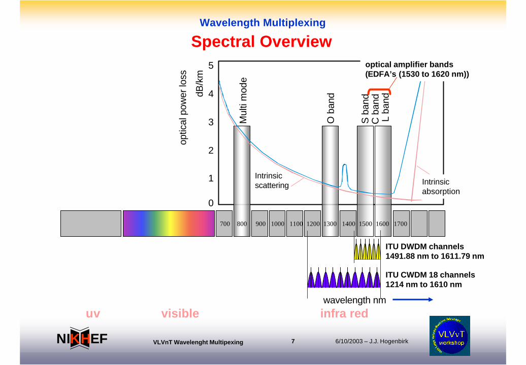
700 800 900 1000 1100 1200 1300 1400 1500 1600 1700
uv visible infra redwavelength nm
0
1
2
3
4
5
optic
al p
ower
loss
dB/k
m
Intrinsicscattering Intrinsic
absorption
S b
and
L ba
nd
Mul
ti m
ode
O b
and
C b
and
optical amplifier bands(EDFA’s (1530 to 1620 nm))
ITU DWDM channels1491.88 nm to 1611.79 nm
ITU CWDM 18 channels1214 nm to 1610 nm
Spectral Overview
6/10/2003 – J.J. HogenbirkVLVnT Wavelenght Multipexing 8EFNI HK
Wavelength Multiplexing
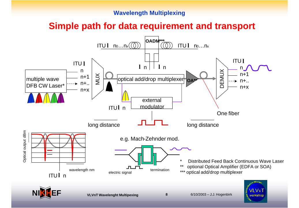
ITU λnn+1n+..n+x
multiple wave DFB CW Laser*
externalmodulatorITU λ n
ITU λnn+1n+..n+x
optical add/drop multiplexer
electric signalwavelength nm
Opt
ical
out
put
dBm
* Distributed Feed Back Continuous Wave Laser ** optional Optical Amplifier (EDFA or SOA)*** optical add/drop multiplexer
ITU n λtermination
e.g. Mach-Zehnder mod.
OADM***ITU λ n0…nx ITU λ n0…nx
λ λn n
OA**
One fiber
MU
X
DE
MU
X
long distance long distance
Simple path for data requirement and transport

6/10/2003 – J.J. HogenbirkVLVnT Wavelenght Multipexing 9EFNI HK
Wavelength Multiplexing
Pump laser980 nm or 1480 nm
Pump laser980 nm or 1480 nm
Erbium-doped fiberCa 15 m
Optical isolatorOptical isolator
Dispersion compensating fiber
time fiber time
Many optical parts are passive and bi-directional (No optical to electric to optical needed)All optical switchingCare for dispersion compensationRestoration optical power if necessaryMany manufactures
Attenuation and dispersion
Some technical aspects on fiber
6/10/2003 – J.J. HogenbirkVLVnT Wavelenght Multipexing 10EFNI HK
Wavelength Multiplexing
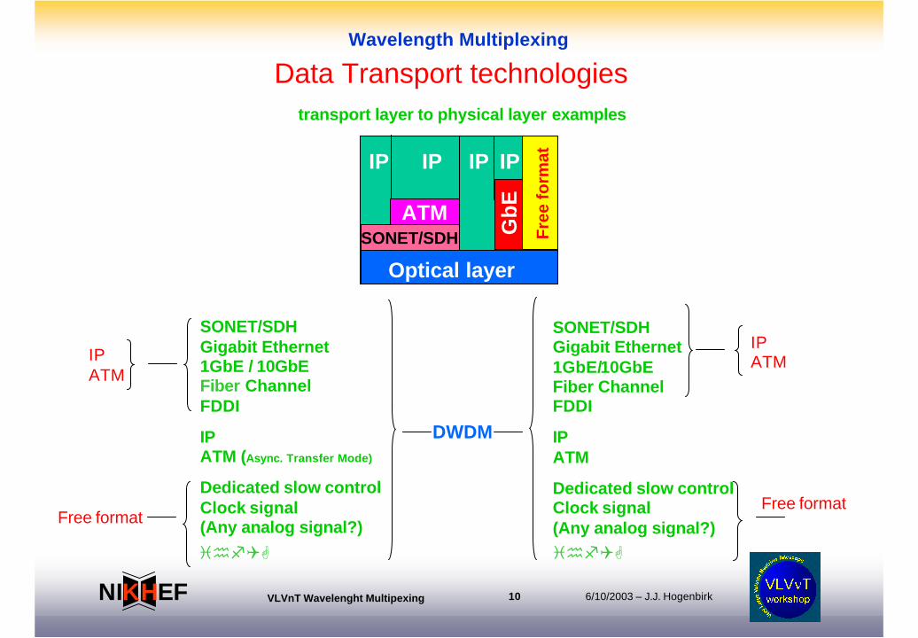
Data Transport technologies
SONET/SDHGigabit Ethernet1GbE / 10GbEFiber ChannelFDDI
IPATM (Async. Transfer Mode)
Dedicated slow controlClock signal(Any analog signal?)
IPATM
DWDM
SONET/SDHGigabit Ethernet1GbE/10GbEFiber ChannelFDDI
IPATM
Dedicated slow controlClock signal(Any analog signal?)
IPATM
Free formatFree format
IP
Optical layer
Gb
E
ATMSONET/SDH F
ree
form
atIP IP IP
transport layer to physical layer examples
ihfQG ihfQG
6/10/2003 – J.J. HogenbirkVLVnT Wavelenght Multipexing 11EFNI HK
Wavelength Multiplexing
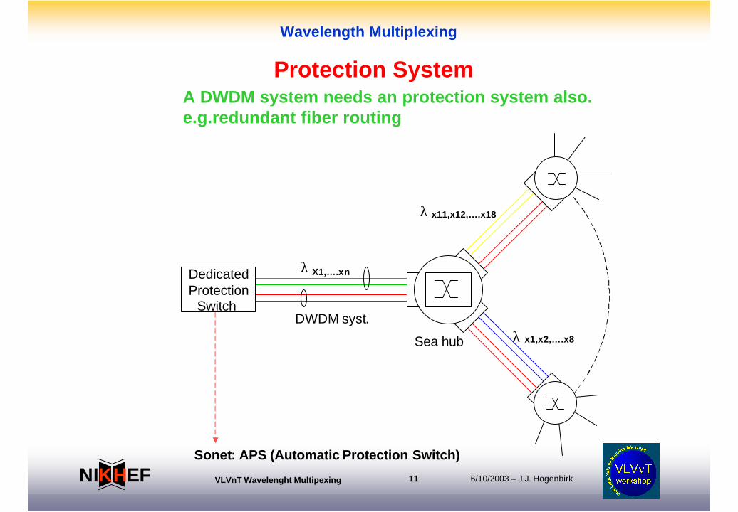
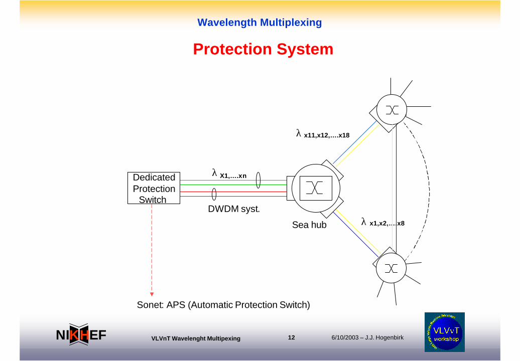
DedicatedProtection
Switch DWDM syst.
Sea hub
Sonet: APS (Automatic Protection Switch)
λ
x1,x2,….x8
x11,x12,….x18
X1,….xn
λ
λ
A DWDM system needs an protection system also.e.g.redundant fiber routing
Protection System
6/10/2003 – J.J. HogenbirkVLVnT Wavelenght Multipexing 12EFNI HK
Wavelength Multiplexing
DedicatedProtection
Switch DWDM syst.
Sea hub
Sonet: APS (Automatic Protection Switch)
λ
x1,x2,….x8
x11,x12,….x18
X1,….xn
λ
λ
Protection System
6/10/2003 – J.J. HogenbirkVLVnT Wavelenght Multipexing 13EFNI HK
Wavelength Multiplexing
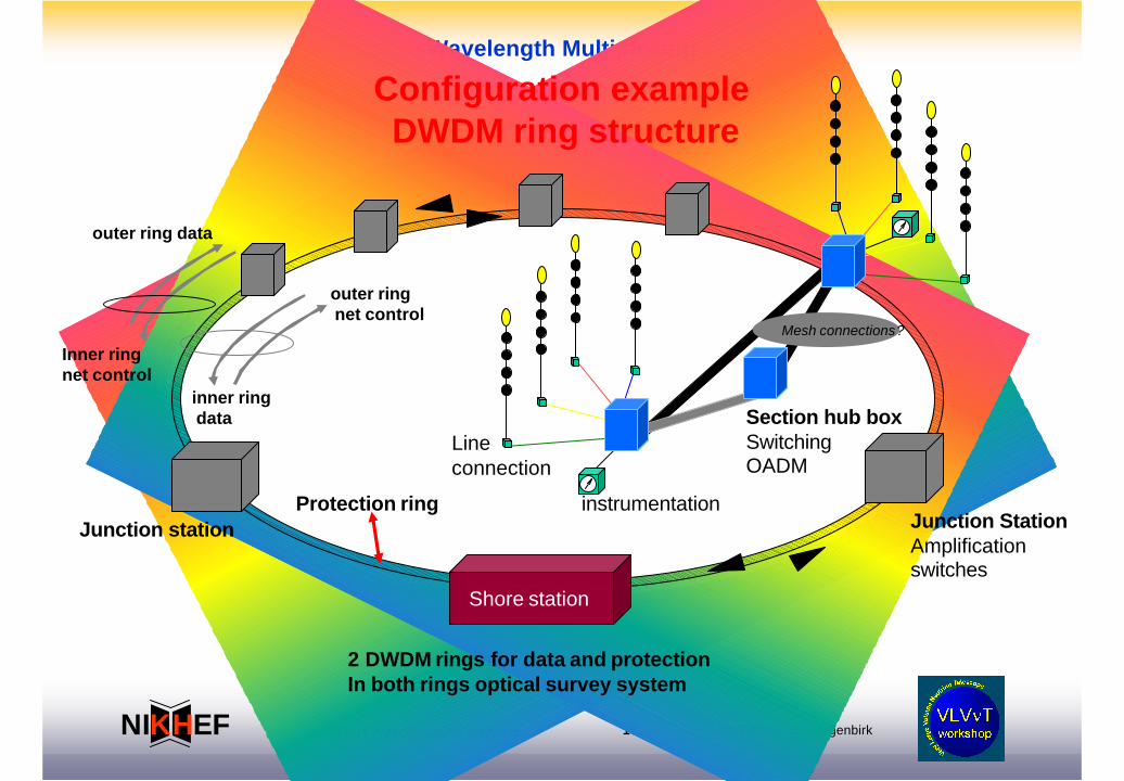
Shore station
Junction station Junction StationAmplificationswitches
Section hub boxSwitchingOADM
Line connection
Mesh connections?
2 DWDM rings for data and protectionIn both rings optical survey system
instrumentationProtection ring
Configuration example DWDM ring structure
outer ring data
Inner ringnet control
inner ringdata
outer ringnet control
6/10/2003 – J.J. HogenbirkVLVnT Wavelenght Multipexing 14EFNI HK
Wavelength Multiplexing
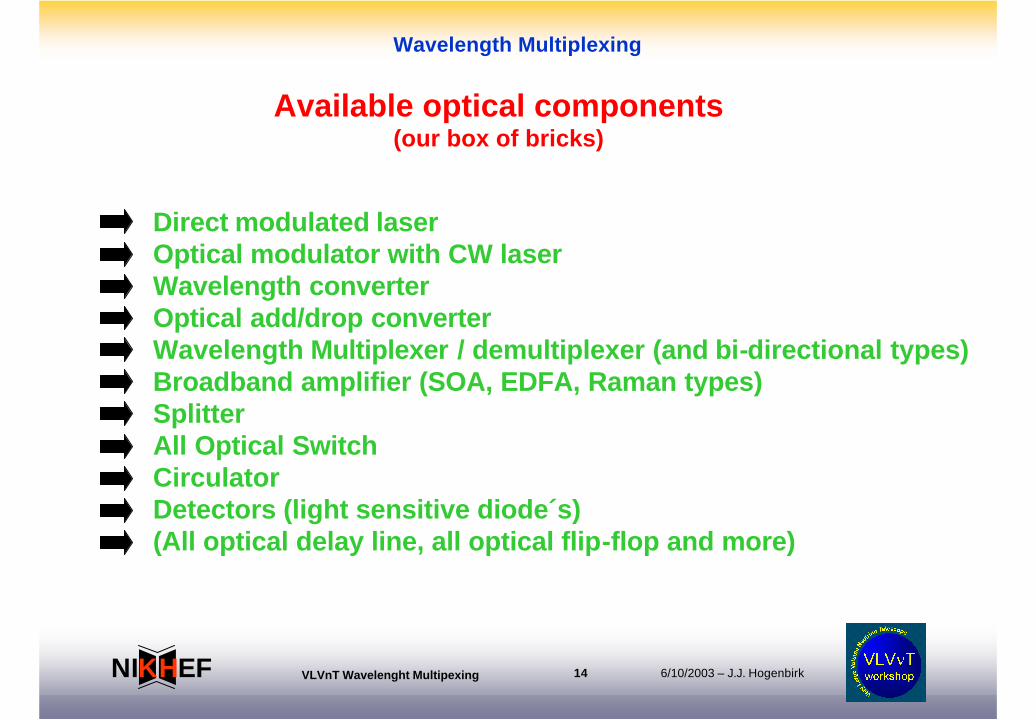
Direct modulated laserOptical modulator with CW laserWavelength converterOptical add/drop converterWavelength Multiplexer / demultiplexer (and bi-directional types)Broadband amplifier (SOA, EDFA, Raman types)SplitterAll Optical SwitchCirculatorDetectors (light sensitive diode´s)(All optical delay line, all optical flip-flop and more)
Available optical components(our box of bricks)
6/10/2003 – J.J. HogenbirkVLVnT Wavelenght Multipexing 15EFNI HK
Wavelength Multiplexing
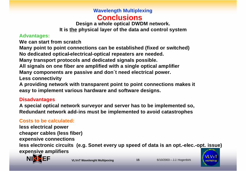
ConclusionsDesign a whole optical DWDM network.
It is the physical layer of the data and control systemAdvantages:We can start from scratchMany point to point connections can be established (fixed or switched)No dedicated optical-electrical-optical repeaters are needed. Many transport protocols and dedicated signals possible.All signals on one fiber are amplified with a single optical amplifierMany components are passive and don´t need electrical power.Less connectivityA providing network with transparent point to point connections makes iteasy to implement various hardware and software designs.
DisadvantagesA special optical network surveyor and server has to be implemented so,Redundant network add-ins must be implemented to avoid catastrophes
Costs to be calculated:less electrical powercheaper cables (less fiber)expensive connectionsless electronic circuits (e.g. Sonet every up speed of data is an opt.-elec.-opt. issue)expensive amplifiers
6/10/2003 – J.J. HogenbirkVLVnT Wavelenght Multipexing 16EFNI HK
Wavelength Multiplexing
The question is not:
Weather we will have Gigabit networks in the future
The question is:
When we will have Gigabit networks in the future available
Saying From:1. National coordination office for HPCC (High performance Computing and Communication)2. The Corporation for National Research Initiatives3. IEEE communications Society Technical Committee on Gigabit Networking