Embed Size (px)
Citation preview
NSPO-PROC-0031 Issue 00 Revision 00
2003/4/9
AMS-02 QM J-crate Thermal Vacuum/ Thermal Balance Test Procedure
This document shall not be disclosed outside of the National Space Program Office (NSPO), National Science Council. Executive Yuan, Republic of China, and shall not be duplicated in whole or in part for any purpose without permission from NSPO
National Space Program Office
國 家 太 空 計 畫 室
NSPO-PROC-0031 0000
2003/4/9 AMS-02 QM J-crate TV/TB
Test Procedure 2 of 75
AMS-02 QM J-crate Thermal Vacuum/ Thermal Balance Test Procedure
Approval by:
核可 蔡志然/ME Sec. Date
Reviewed by:
審查 黃正德/ME Sec. Date 蔡旭東/MIT at CERN Date
林志陽/ IT Sec. Date 吳高志/ QA Sec. Date
Name/Title Date Name/Title Date
Name/Title Date Name/Title Date
Name/Title Date Name/Title Date
Prepared by:
擬訂 陳嘉瑞/ME Sec. Date
National Space Program Office
國 家 太 空 計 畫 室

NSPO-PROC-0031 0000
2003/4/9 AMS-02 QM J-crate TV/TB
Test Procedure 3 of 75
Revision/Change Record
改版/變更記錄
Symbol
記號
Document Date
文件日期
Authorization Date
核可日期
Revision / Change Description
改版/變更說明
Pages Affected
影響頁次
0000
2002/12/06 2002/12/09 New Issue All
NSPO-PROC-0031 0000
2003/4/9 AMS-02 QM J-crate TV/TB
Test Procedure 4 of 75
CONTENTS Page 1.0 SCOPE 10 1.1 Introduction 10
1.2 Equipment to be Tested 10 1.3 Test Objectives 10 1.3.1 Thermal Cycle Test Objectives 10
1.3.2 Thermal Balance Test Objectives 10 1.4 Test Description 10 1.5 Test Method 10 1.6 QM J-crate Test Configuration 11
2.0 CONDITIONS 12
2.1 Personnel 12 2.2 Special Hazards and Precautions 13
2.2.1 QM J-crate Handling 13 2.2.2 Contamination Control 14 2.2.3 Electrostatic Discharge 14
2.3 Test Preparation 14
2.3.1 Communications 14 2.3.2 Utilities 14 2.3.3 Documentation 14 2.3.4 Environmental Test Equipment 14 2.3.5 TVC Interface Adapter 15 2.3.6 Emergency Power 16
2.4 Definitions 16 2.4.1 Environmental Control Test Tolerances 16 2.4.2 QM J-crate Test Equipment Set-up 16 2.4.3 Test Article Control Temperature 16 2.4.4 Room Ambient 16 2.4.5 Temperature Stabilization 16
2.4.5.1 Thermal Cycle Testing 16 2.4.5.2 Thermal Balance Testing 17
2.4.6 Temperature Transition Rates 17 2.4.7 Test Tolerance 17 2.4.8 QM J-crate Thermal Control Temperature Limits 17
3.0 DATA REQUIREMENTS 18
3.1 Environmental Data to be Recorded 18
NSPO-PROC-0031 0000
2003/4/9 AMS-02 QM J-crate TV/TB
Test Procedure 5 of 75
3.2 Recording Frequency 18 3.3 Data Trends 18 3.4 Out-of-Tolerance Condition 18
4.0 TEST PREPARATION 19
4.1 QM J-crate Instrumentation 19 4.1.1 Test Thermocouples 19 4.1.2 Test Only Heaters 19
4.2 Chamber Configuration 19 4.2.1 Port Plates 19 4.2.2 TVC Instrumentation 20 4.2.3 Test Set Placement 20
4.3 Chamber Loading 20
4.3.1 QM J-crate and TVC Interface Adapter 20
4.4 Final Hook-Up and Check-out 20 4.4.1 Test Set to QM J-crate Connections 20 4.4.2 Test Heater Verification 21 4.4.3 Chamber Fixture Thermocouples 21 4.4.4 Thermal Insulation Installation 21 4.4.5 Contamination Witness Plates 21
5.0 TEST CONDUCT 21
5.1 Test ΦA, Chamber Evacuation 22 5.2 Test ΦB, Non-Operating Cycle #1 22 5.3 Test ΦC, Operating Hot Cycle #1 23 5.4 Test ΦD, Non-Operating Cold Cycle #1 24 5.5 Test ΦE, Operating Cold Cycle #1 25 5.6 Test ΦF, Operating Hot Cycle #2 26 5.7 Test ΦG, Operating Cold Cycle #2 27 5.8 Test ΦH, Operating Hot Cycle #3 27 5.9 Test ΦI, Operating Cold Cycle #3 28 5.10 Test ΦJ, Non-Operating Hot Cycle #4 29 5.11 Test ΦK, Operating Hot Cycle #4 30 5.12 Test ΦL, Non-Operating Cold Cycle #4 31 5.13 Test ΦM, Operating Cold Cycle #4 32 5.14 Test ΦN, Cold Thermal Balance Test 33 5.15 Test ΦO, Hot Thermal Balance Test 34 5.16 Test ΦP, Transient Cool-Down Test 35 5.17 Test ΦQ, Return to Room Ambient Conditions 35
NSPO-PROC-0031 0000
2003/4/9 AMS-02 QM J-crate TV/TB
Test Procedure 6 of 75
APPENDIX A CTE Listing 61 B Test Procedures for J-Crate (QM) Environmental Tests 63
NSPO-PROC-0031 0000
2003/4/9 AMS-02 QM J-crate TV/TB
Test Procedure 7 of 75
TABLES Page I Test Only Heater Control Requirements 39-42
II Monitoring and Heater-Controlled Thermocouple Locations and Limits 43
III Test Only Heater Locations & Requirements 44
NSPO-PROC-0031 0000
2003/4/9 AMS-02 QM J-crate TV/TB
Test Procedure 8 of 75
FIGURES Page
1 QM J-crate Test Configuration 44
2 QM J-crate Thermal Vacuum/ Thermal Balance Test Sequence 45
3 External surfaces of QM J-crate test configuration 46
4 Test adapter 47
5 QM J-Crate Thermal Vacuum Test Electrical Test Set-up 48
6 Test only heaters and thermocouples locations for top main wall 49
7 Test only heaters and thermocouples locations for bottom main wall 50
8 Test only heaters and thermocouples locations for right side wall 51
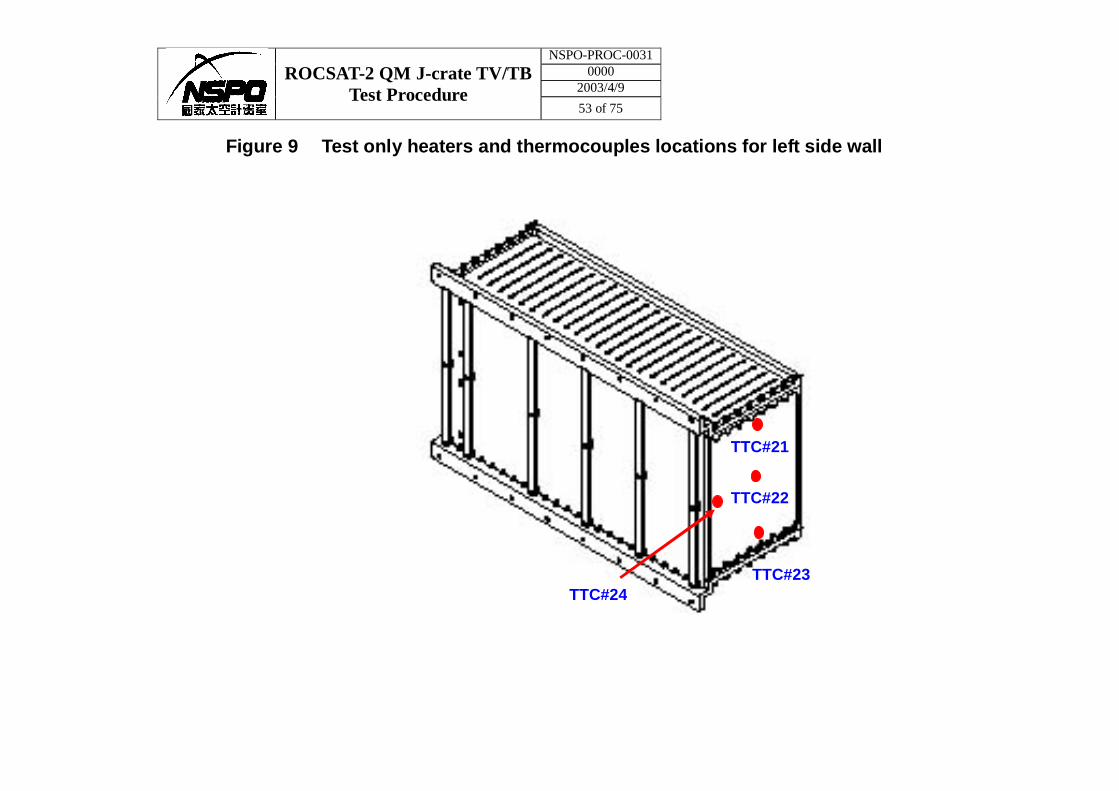
9 Test only heaters and thermocouples locations for left side wall 52
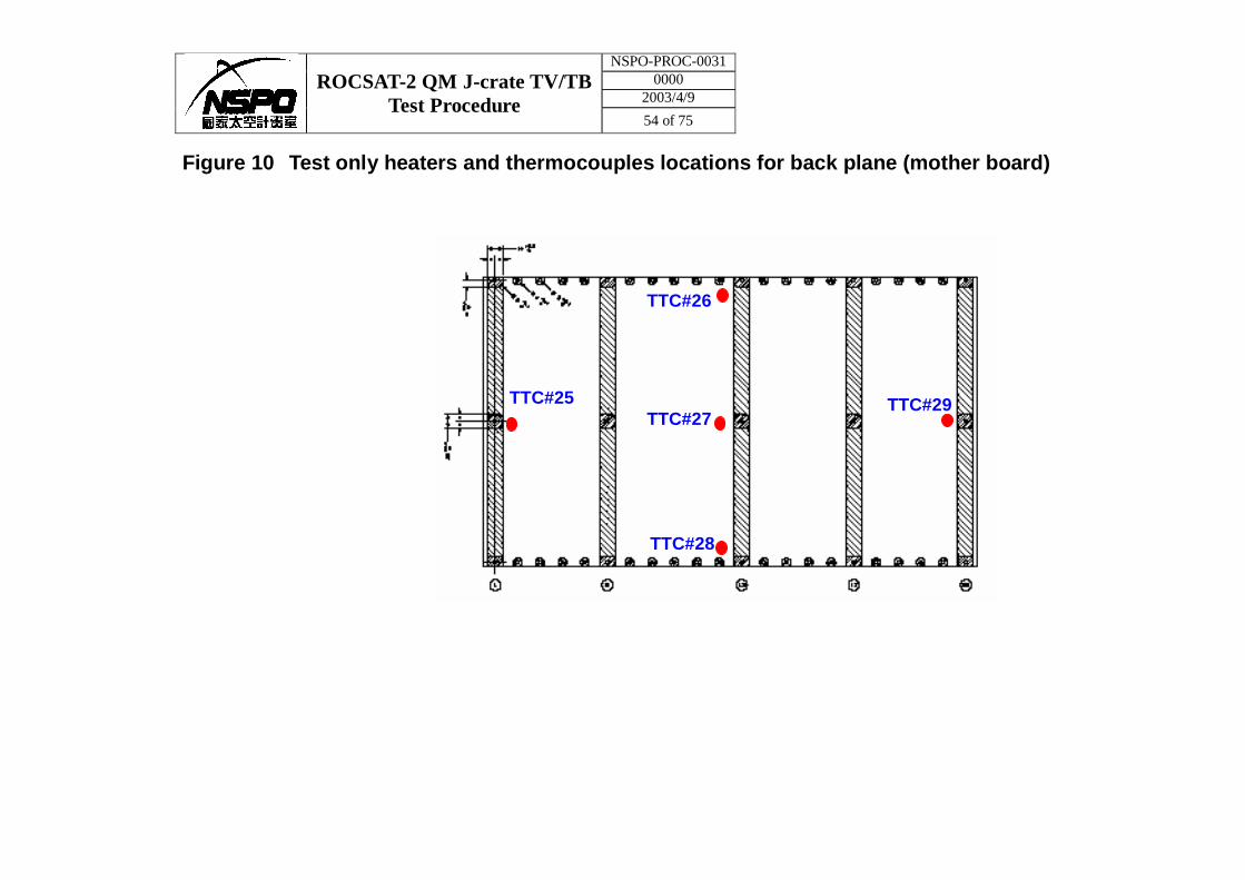
10 Test only heaters and thermocouples locations for back plane 53
11 Test only heaters and thermocouples locations for left side wall (mother board) 54
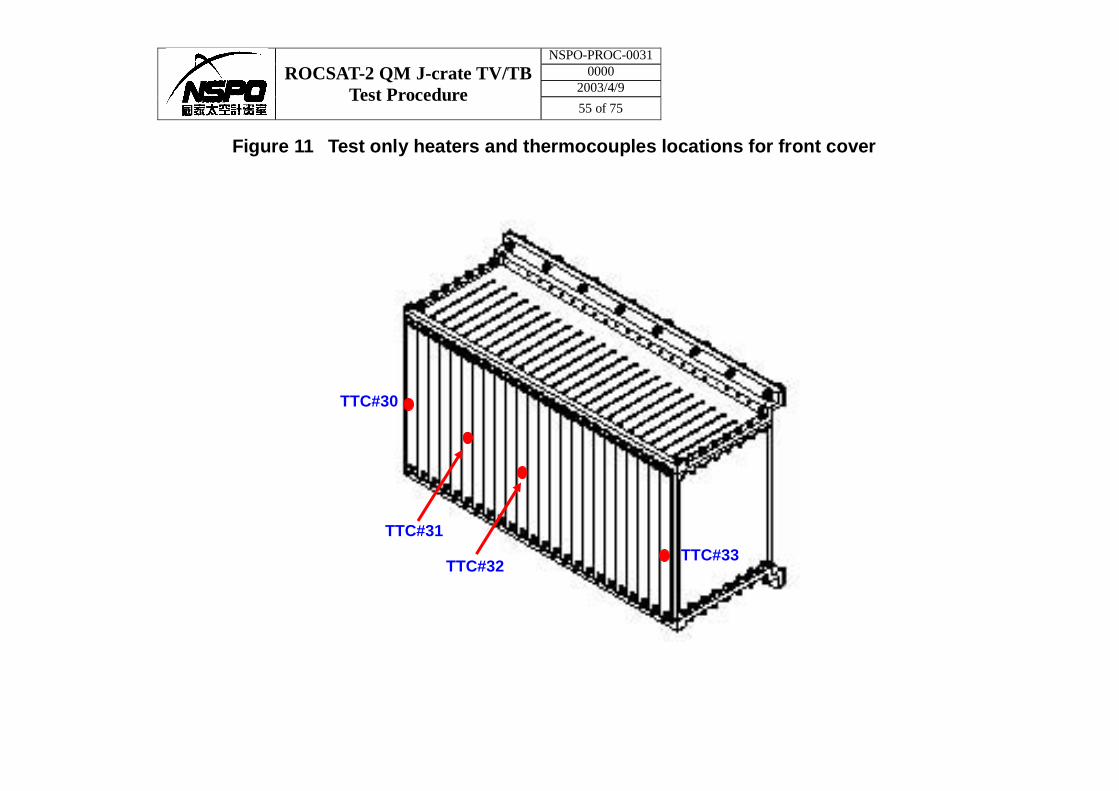
12 Test only heaters and thermocouples locations for front 55
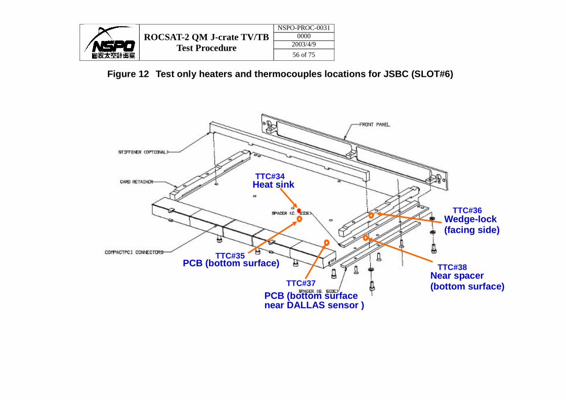
13 Test only heaters and thermocouples locations for JSBC1 (SLOT#6) 56
14 Test only heaters and thermocouples locations for JHIF board 57
15 Test only heaters and thermocouples locations for mounting feet 58
16 Test only heaters and thermocouples locations for test adapter 59
17 Test only heaters and thermocouples locations for thermal baseplate 60
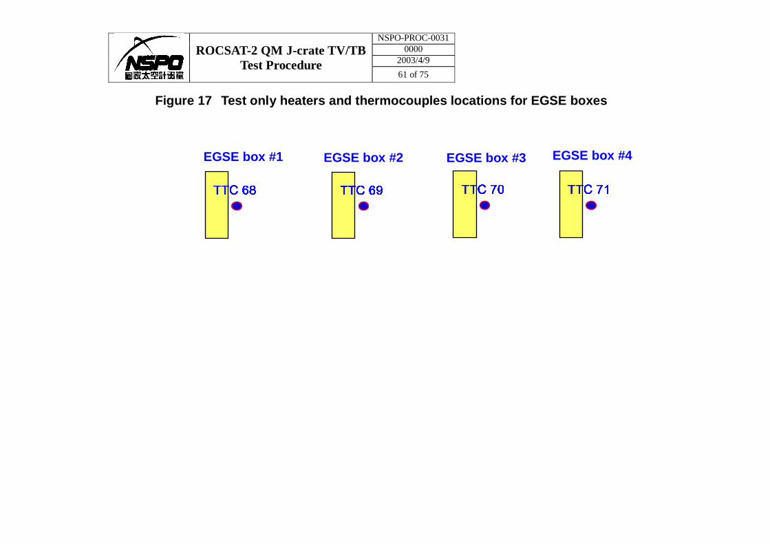
18 Test only heaters and thermocouples locations for EGSE boxes 61
NSPO-PROC-0031 0000
2003/4/9 AMS-02 QM J-crate TV/TB
Test Procedure 9 of 75
Listed below are the paragraph numbers and brief descriptions of the detailed alerts/cautions contained within this procedure. Safety Located in On Alert Paragraph Page Area of Concern
1 2.2 13 Special Hazards & Precautions
2 2.2(c) 13 Safe Chamber Oxygen Levels
3 2.2.3 13 Electrostatic Discharge
4 5.17 36 Safe Chamber Oxygen Levels
SAFETY ALERTS
NSPO-PROC-0031 0000
2003/4/9 ROCSAT-2 QM J-crate TV/TB
Test Procedure 10 of 75
AMS-02 QM J-crate THERMAL VACUUM/THERMAL BALANCE TEST PROCEDURE 1.0 SCOPE
1.1 Introduction. This procedure defines the thermal vacuum environment and detailed procedure for the environmental THERMAL CYCLE/ THERMAL BALANCE testing of the QM J-crate.
1.2 Equipment to be Tested. The article to be thermal vacuum tested per this
procedure is the QM J-crate.
1.3 Test Objectives.
1.3.1 Thermal Cycle Test Objectives. The purpose of the thermal cycle test is to demonstrate the ability of the QM J-crate to meet design requirements under vacuum conditions and temperature extremes four (4) hot/cold cycles at protoflight levels.
1.3.2 Thermal Balance Test Objectives. The purposes of the thermal balance test
are to obtain thermal data for the correlation and correction of the QM J-crate Thermal Analytical Model.
1.4 Test Description. The QM J-crate shall be subjected to a total of five (5)
temperature cycles. A temperature cycle begins at room ambient temperature, proceeds to hot test temperatures, then to cold test temperatures, and finally back to room ambient.
• Hot and Cold Thermal Balance Tests will be conducted during the last (5th)
cycle. During the thermal balance and thermal cycle test the QM J-crate mounting interface will be subjected to the thermal extremes under vacuum conditions.
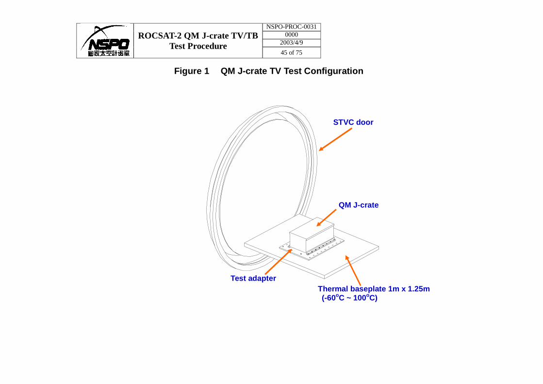
1.5 Test Method. The QM J-crate will be mounted on thermal baseplate inside Small
Thermal Vacuum Chamber (STVC), shown in Figure 1. The test will be conducted in that STVC under vacuum conditions. Only mounting interface of QM J-crate will be thermally cycled with test adapter attached with test heaters and STVC thermal baseplate filled with GN2.
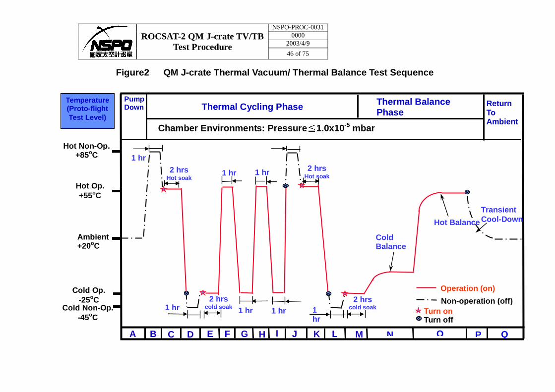
Figure 2 graphically depicts the thermal test profile and Table I lists the temperature controlling criteria applicable to each phase. Details of the test article instrumentation and the test set-up are depicted in Figures 3 through 158.

NSPO-PROC-0031 0000
2003/4/9 ROCSAT-2 QM J-crate TV/TB
Test Procedure 11 of 75
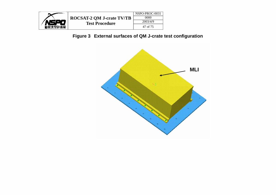
1.6 QM J-crate Test Configuration. The QM J-crate will be mounted on test adapter with
thermal filler, Cho-Therm, between them. Test adapter will be mounted on thermal baseplate with thermal filler, Cho-Therm, between them. Thermal baseplate is hanged on STVC door, shown in figure 1. Test thermal blankets (MLI) will cover the external surfaces of QM J-crate except the bottom one, shown in figure 3.
NSPO-PROC-0031 0000
2003/4/9 ROCSAT-2 QM J-crate TV/TB
Test Procedure 12 of 75
2.0 CONDITIONS
2.1 Personnel. The following personnel will be present to conduct or observe the test or on-call during the set-up and conduct of the test, as required.
CTC Crate Test Conductor:
Has overall responsibility for the thermal vacuum testing of the QM J-crate, installation and hook-up of test sets and the QM J-crate into the STVC.
ETE Electrical Test Engineer:
The Electrical Test Engineer has responsibility for the J-crate test procedure, Automated Test Sequence (ATS), test aids, and test set software development. ETE also support T/V test preps activities. ETE lead trouble shooting activities and anomaly resolution teams.
TDE Thermal Design Engineer:
Prior to the T/V test, shall perform the pre-T/V test thermal analysis to determine the thermocouple and test-only heater locations and powers for each phase of T/V testing. Shall monitor the overall thermal operation of the test and, with the aid of the TTE, be responsible for maintaining the temperature requirements specified in Table I of this document during the test.
TTE Thermal Test Engineer:
TTT Thermal Test Technician:
During test preparations and setup activities prior to the T/V test, the TTE or TTT will be responsible for all activities directly related to the test. Will install all instrumentation particular to the T/V test, i.e. thermocouples and test only heaters. TTE or TTT will have responsibility for control of the test only heaters and monitor the temperature sensors during the conduct of the test. Will record the thermal data as directed. Will operate the thermal vacuum test chamber and other vacuum related tasks as directed. TTE will be the primary contact between TVC control room and all other organizations before, during and after the test. During the test will monitor the overall vacuum chamber operations, thermal test section personnel activities, and support the CTC and TDE as needed.
TIE Thermal Insulation Engineer:
Will install and manage thermal insulation as directed by the TDE.
NSPO-PROC-0031 0000
2003/4/9 ROCSAT-2 QM J-crate TV/TB
Test Procedure 13 of 75
MTC Mechanical Test Conductor:
Will be responsible for all QM J-crate related ground handling activities.
QA Quality Assurance Representative:
Will monitor the handling operation of the QM J-crate during transportation, installation into, and removal from the STVC. Will review and verify the acceptance or rejection of all test data.
2.2 Special Hazards and Precautions.
(a) Wrist-stats (ground straps) will be worn at all times when working near or when in actual contact with QM J-crate.
(b) The number of personnel present will be kept to an absolute minimum at all
times while QM J-crate is in the T/V area.
(c) All personnel will observe oxygen deficiency safety rules.
∗∗∗∗∗∗∗∗∗∗∗∗∗∗∗∗∗∗∗∗∗∗∗∗∗ CAUTION∗∗∗∗∗∗∗∗∗∗∗∗∗∗∗∗∗∗∗∗∗∗∗∗∗∗∗∗ NO ONE WILL BE ALLOWED TO ENTER THE THERMAL VACUUM TEST CHAMBER UNTIL THE OXYGEN LEVEL HAS BEEN VERIFIED SAFE USING AN OXYGEN ANALYZER. (OXYGEN LEVELS ARE CONSIDERED SAFE WHEN THE CHAMBER AIR CONTAINS A MINIMUM OF 19.5% OXYGEN.) ∗∗∗∗∗∗∗∗∗∗∗∗∗∗∗∗∗∗∗∗∗∗∗∗∗∗∗∗∗∗∗∗∗∗∗∗∗∗∗∗∗∗∗∗∗∗∗∗∗∗∗∗∗∗∗∗∗∗∗∗∗∗∗
(d) All personnel shall maintain continuous vigilance for conditions which may
endanger personnel conducting the test or the equipment being tested. Any conditions which appear hazardous shall promptly be brought to the attention of the CTC and/or the TTE.
2.2.1 QM J-crate Handling.
The MTC shall be responsible for all QM J-crate handling operations. The TTE or TTT will assist as directed by the MTC.
2.2.2 Contamination Control.
The contamination control engineer will inspect the chamber and grant approval prior to the installation of the QM J-crate into the STVC. All test cables inside STVC shall be vacuum approved.
2.2.3 Electrostatic Discharge.
The possibility of an electrostatic discharge to the QM J-crate will be minimized.
NSPO-PROC-0031 0000
2003/4/9 ROCSAT-2 QM J-crate TV/TB
Test Procedure 14 of 75
2.3 Test Preparation.
2.3.1 Communications.
Verbal communications will be sufficient to cover these procedure operations.
2.3.2 Utilities.
Only normal test utilities are required. In the event of a facility power outage, an interlock system will close all gate valves on the test chamber. Power will be automatically supplied by UPS located in the TV machine room.
2.3.3 Documentation.
Documents Required on Hand.
A current revision of the following documents must be on hand at the start of and throughout the T/V test. Test Procedure for J-Crate (QM) Environmental Tests (CERN) Functional Test Descriptions for J-Crate (QM) Environmental Tests (CERN) J-Crate (Qualification Module) Thermal Vacuum Test Interface Document (CERN) NSPO-PROC-0031............ AMS-02 QM J-crate Thermal Vacuum/ Thermal Balance Test Procedure.
NSPO-PROC-0029............Small Thermal Vacuum Chamber Operation Procedure NSPO-PROC-0030............Small Thermal Vacuum Chamber Emergency Procedure NSPO-PROC-0027............TDHS/HCS-II Operation Procedure NSPO-PROC-0028............TDHS/HCS-II Emergency Procedure NSPO-PROC-0006............Heater Installation/ Removal/Checkout Process Specification NSPO-PROC-0020............Thermocouple End-to-end Verification Procedure NSPO-PROC-0021............Thermocouple Installation/ Removal/Checkout Process Specification
Reference Documents.
2.3.4 Environmental Test Equipment.
The following equipment or their equivalent is required for the conduct of this test.
NSPO-PROC-0031 0000
2003/4/9 ROCSAT-2 QM J-crate TV/TB
Test Procedure 15 of 75
NOTE: All equipment that require calibration shall have current calibration stickers. Calibration dates shall not expire during the anticipated test duration.
(a) Small Thermal Vacuum Chamber with its associated operating equipment. The chamber will be capable of maintaining a pressure of 1.0 X 10⁻⁵ mbar, or less, while containing the QM J-crate under test. The STVC thermal baseplate will be filled with GN2 ranging from –60°C to +100°C.
(b) A temperature readout/recording device. The device will be of the multi-channel variety capable of reading copper/constantan (type T) thermocouples with an accuracy of ±1.0°C or better. (c) Thermal Data Handling System and Heater Control System, or equivalent.
(d) The vacuum chamber feedthrough requirements are as follows:
5 24 pin Deutsch power feedthrough (DM5623-37-2P/P)
6 37 pin Deutsch T-type thermocouple feedthrough 4 55 pin Deutsch feedthrough (951-B07H-2-55-PS-50)
Record the environmental test in the Custodial Test Equipment (CTE) listing embodied in this procedure as Appendix A.
CTE List Completed ___________TTE or TTT
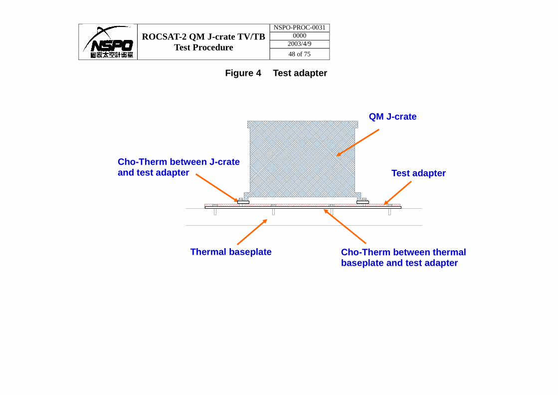
2.3.5 Test Adapter.
Test adapter is treated as simulated thermal interface, AMS-02 radiator panel. The QM J-crate will be mounted on thermal baseplate with test adapter, shown in Figure 4. This test adapter is used as an interface to solve problem of unfitted screw holes between QM J-crate and thermal baseplate. Besides, test heaters will be applied on test adapter to precisely control its temperature.
2.3.6 Emergency Power.
A 160KW UPS located inside the TV machine room will provide emergency power for STVC control system should the normal facility power be interrupted. The UPS is programmed to start automatically in the event of a facilities power outage, and the emergency power generator will take over the normal power supply to STVC within 15 seconds without interrupting the power supply to test facilities. When normal facility power is restored, the
NSPO-PROC-0031 0000
2003/4/9 ROCSAT-2 QM J-crate TV/TB
Test Procedure 16 of 75
UPS and EPS will return to their normal standby condition.
2.4 Definitions
2.4.1 Test conditions.
The thermal vacuum test sequence is graphically depicted in Figure 1 and described in Section 5.0. In the event that special tests, i.e. partial repeat testing, are required, they may be performed by STP or documenting on a TRS.
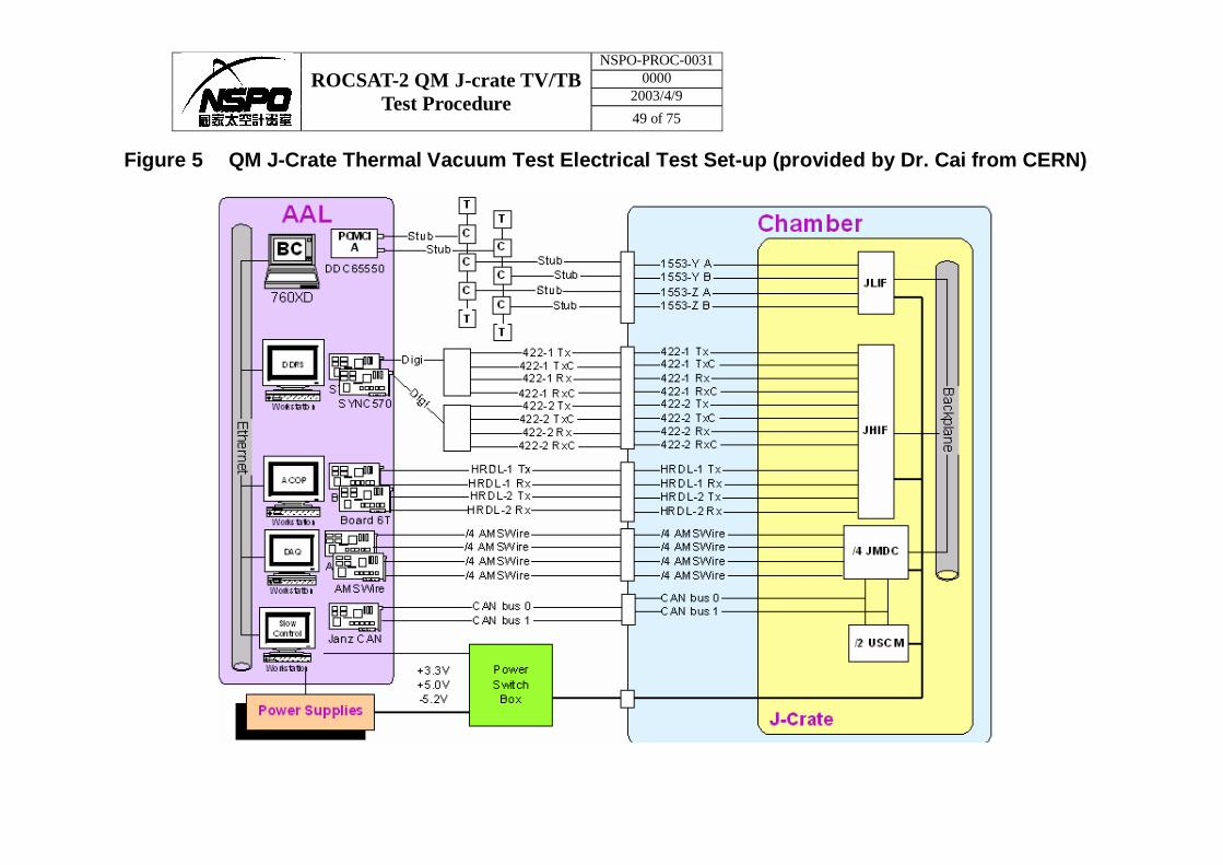
2.4.2 QM J-crate Test Equipment Set-up.
Test equipment set-up prepared by AMS-02 team is shown in Figure 5. There will be four personal computers located around STVC. Power supply will be used to provide DC voltage power to QM J-crate because JPD is not ready yet. Another 3 personal computers will be located in TVC control room to monitor test data. Four 55 pin feedthroughs will be used for communication signals and two 24 pin feedthroughs will be used for power supply. Four small boxes for RS232 cable will be installed inside STVC and will be thermally isolated with thermal baseplate with Teflon block.
2.4.3 Test Article Control Temperature.
Control thermocouples used to monitor the test article and any additional required thermocouples as listed in Table II.
2.4.4 Room Ambient. Room ambient conditions are defined as:
• Pressure: 1013±40 mbar
• Temperature: 22±3°C
• Relative Humidity: 50±20%
2.4.5 Temperature Stabilization.
2.4.5.1 Thermal Cycle Testing.
For the purpose of thermal cycle testing, unless otherwise specified by the TDE, temperature stabilization shall be considered attained when:
NSPO-PROC-0031 0000
2003/4/9 ROCSAT-2 QM J-crate TV/TB
Test Procedure 17 of 75
1. The mounting feet, TTC# 44 - 47, are within 2°C of the specified
proto-flight temperature limit. and
2. No crate mounted thermocouple is varying at a rate greater than
1°C/hr as measured over a period not less than one (1) hour.
2.4.5.2 Thermal Balance Testing.
For the purpose of thermal balance testing, unless otherwise specified by the TDE, temperature stabilization shall be considered attained when:
1. No crate mounted thermocouple is varying at a rate greater than 0.5°C/hr as measured over a period not less than one (1) hr.,
and
2. All heater settings remain unchanged over a two (2) hour period which will include the 1 hour period outlined above.
2.4.6 Temperature Transition Rates.
The temperature transition rate shall be limited to a rate equal to or less than 1°C/min as measured by the test article control thermocouples.
2.4.7 Test Tolerance.
The maximum allowable tolerances, excluding instrument error, for environmental test conditions as follows:
• All temperatures shall be controlled to within 1°C.
• All vacuum levels shall be maintained at 1X10⁻⁵ mbar or less.
NOTE: Closer tolerances may be imposed during the thermal balance portion of the test at the discretion of the TDE.
2.4.8 QM J-Crate Thermal Control and Temperature Limits.
Test control parameters are detailed in Table I. Temperature limits of test thermocouples can be found in Table II.
NSPO-PROC-0031 0000
2003/4/9 ROCSAT-2 QM J-crate TV/TB
Test Procedure 18 of 75
3.0 DATA REQUIREMENTS.
3.1 Environmental Data to be Recorded.
Temperature data recording shall be initiated immediately prior to chamber evacuation. All temperature data shall be acquired and recorded by means of a multi-channel temperature measurement system. The record format shall be a sequential tabulation in engineering units (°C) identified per thermocouple number in conformance with the environmental data sheets presented as Table II in this document. Records shall be annotated for time, date, test phase, temperature cycle number, and any other information that may be pertinent, to facilitate subsequent data evaluation.
Test heater data recording shall be initiated when the first individual heater is activated and will be recorded in watts on the environmental data sheets presented as Table III in this document. The TTE or TTT will be to alert to any sudden or unexpected change in power to a circuit. It may be a precursory warning of a impending malfunction of that heater circuit.
3.2 Recording Frequency.
Temperature and power data shall be printed on multi-channel recorders at thirty (30) minute intervals during temperature transitions and at sixty (60) minute intervals, or more often, during and after stabilization. However, the scanning frequency shall be much less than the recording frequency, such as short as 1 minute. Manual entry of environmental data shall be made on the data sheets provided and in the chamber log book at intervals of sixty (60) minutes, or less, and at the end of each test condition.
3.3 Data Trends.
Test personnel shall be alert to temperature data trends indicating degradation which could lead to an out-of-tolerance condition if the test condition were extended. In such cases the CTC shall be apprised of the situation.
3.4 Out-of-Tolerance Condition.
Operation outside the tolerance limits, or failure to meet the requirements prescribed in this document or in the spacecraft test procedure shall be handled.
Testing shall not continue until satisfactory corrective action has been taken. If the failure is of such a nature that additional testing are required or deemed advisable, special tests may be conducted via STP.
NSPO-PROC-0031 0000
2003/4/9 ROCSAT-2 QM J-crate TV/TB
Test Procedure 19 of 75
4.0 TEST PREPARATION.
It is strongly advised that, whenever possible, preparation of the QM J-crate should be performed prior to installation into the small thermal vacuum chamber. Working in the test chamber increases difficulty of any task. 4.1 QM J-crate Instrumentation.
The order of hook-up of the thermocouple and test heaters will be at the discretion of the thermal test personnel. 4.1.1 Test Thermocouples.
Test thermocouples (T/C) will be used to measure the temperatures on the QM J-carte. T/Cs are also used to monitor and control the operation of the test heaters employed for this test. The thermocouple locations along with temperature limits are catalogued in Table II and graphically depicted in various figures contained in this document. Thermocouple installation instructions, wiring assignments, and check-out procedures can be found in NSPO-PROC-0021.
4.1.2 Test Only Heaters.
Test only heaters are installed on test adapter to control its temperature during test. Each of these heaters will have both of the primary and redundant circuits. Additionally, guard heaters will be installed as needed. The test only heater locations along with power limits are indexed in Table III and pictured in various figures contained in this document. Test only heater control criteria along with associated thermocouples can be found in Tables I and III. That control can take the form of either regulating to a specific temperature or constant power setting. Heater installation instructions, wiring assignments, and check-out procedures can be found in NSPO-PROC-0006.
4.2 Chamber Configuration.
Verify the chamber cleanliness is acceptable for the receiving of the AMS-02 QM J-crate.
Contamination Control Eng. _______________ Init & Date
NSPO-PROC-0031 0000
2003/4/9 ROCSAT-2 QM J-crate TV/TB
Test Procedure 20 of 75
4.2.1 Port Plates.
The required TVC port plates are installed utilizing the feedthroughs identified in Paragraph 2.3.4 (d).
4.2.2 STVC Instrumentation.
The thermocouples are installed on main shroud walls and thermal baseplate to monitor the temperatures of these areas. These thermocouples are connected to the chamber control system.
The pressure sensors monitoring the chamber pressure are connected to
the chamber control system.
4.2.3 Test Set Placement.
• Real-time monitoring system is located at TV test checkout room, which is south side of the test chamber.
• STVC, TDHS/HCS-II, and J-crate control consoles are located at TV test
control room, which is south side of the test chamber.
4.3 Chamber Loading.
4.3.1 QM J-crate and STVC Thermal Baseplate.
The STVC thermal baseplate will be installed onto the chamber door and secured properly. The maximum loading capacity of thermal baseplate is 200kg. Hence, 100 kg will be the maximum weight of test article which will be placed on thermal baseplate under 2g proof-load requirement. The QM J-crate will be mounted on thermal baseplate with test adapter. ALL QM J-CRATE HANDLING OPERATIONS AROUND THE CHAMBER AREA WILL BE PERFORMED UNDER THE DIRECTION OF THE MTC WITH THE CONCURRENCE OF THE CTC AND TTE!!
4.4 Final Hook-up and Check-out.
4.4.1 Test Set to QM J-crate Connections.
Connect and verify the operation of all test set and QM J-crate. Test Set and QM J-crate Check-out Complete ________________ ETE
NSPO-PROC-0031 0000
2003/4/9 ROCSAT-2 QM J-crate TV/TB
Test Procedure 21 of 75
4.4.2 Test Heater Verification.
Connect and verify the operation of all test heaters and thermocouples. Test Heater & T/C Check-out Complete ________________ TTE or TTT 4.4.3 Chamber Fixture Thermocouples.
Install/hook-up all chamber fixture thermocouples and record their channel identification and locations in the chamber log book.
Fixture T/C Hook-up Complete: ________________ TTE or TTT
4.4.4 Thermal Insulation Installation.
Thermal insulation will be installed after QM J-crate is mounted on thermal baseplate inside STVC. Final completion of thermal insulation installation will be accomplished just prior to the “ready to start” walk-around.
Thermal Insulation Installation Complete ________________ TIE
4.4.5 Contamination Witness Plates.
NA 5.0 TEST CONDUCT.
Thermal cycle/thermal balance tests shall be conducted in accordance with the following detailed procedure. Test personnel shall thoroughly familiarize themselves with the procedures and equipment prior to the start of the test and/or each operation performed. Test data shall be acquired per the requirements detailed in section 3 of this document. Test personnel shall be alert to data trends indicating situations which could lead to an out-of-tolerance condition if the test period were continued without modification. The Quality Assurance (QA) representative shall verify:
• Satisfactory completion of the test set-up, • Monitor the QM J-crate installation into the test chamber, • Monitor the data during the actual test in the surveillance mode and, upon
satisfactory completion of testing, stamp on the lines provided with a
NSPO-PROC-0031 0000
2003/4/9 ROCSAT-2 QM J-crate TV/TB
Test Procedure 22 of 75
buy-off stamp. 5.1 Test ΦA, Chamber Evacuation.
(a) Verify test preps are complete. _________CTC (b) Close the chamber door. _________CTC (c) Verify QM J-crate is off. _________ETE (d) Begin evacuation of the thermal vacuum chamber per NSPO-PROC-0029.
Record start time below.
CHAMBER EVACUATION START:
__________________ TIME ________________ DATE
__________________ TTE or TTT ________________ QA
Test Phase A will be considered complete when the chamber pressure is 1.0 x 10⁻⁵ mbar, or less.
Test ΦA Complete. ___________ Time _________ Date
__________________ TTE or TTT ________________ QA
5.2 Test ΦB, Non-operating Hot Cycle #1.
(a) Maintain a chamber pressure of 1.0 x 10⁻⁵ mbar, or less. (b) Data Acquisition Requirements:
1. Record thermocouple and heater data every 20 sec throughout the test per NSPO-PROC-0027.
2. Tabulate thermocouple and heater data hourly and at the end of each test phase per NSPO-PROC-0027.
3. Record additional data and plot as directed by the TTE or TDE. (c) Verify/adjust thermal baseplate and the test heaters and per
NSPO-PROC-0029 and NSPO-PROC-0027 as required to attain the levels listed in Table I for Test Phase B1 and hold for stabilization.
________TDE
NSPO-PROC-0031 0000
2003/4/9 ROCSAT-2 QM J-crate TV/TB
Test Procedure 23 of 75
(d) Change to Test Phase B2 as directed by TDE for a minimum of one (1)
hour after mounting feet, TTC# 44-47, are within 2°C of their hot protoflight operating temperature limit listed in Table II.
________TDE
NOTE: Heater power settings listed in Table I may be modified at the discretion of the TDE to expedite temperature transition or maintain component temperature levels.
(d) At the end of the hold, the TTE or TTT will notify the CTC and when
directed by the CTC, record all environmental and proceed to the next step.
Non-operating Hot Cycle #1 Complete.__________ Time_________ Date
_____________ TDE _____________ ETE ___________QA
5.3 Test ΦC, Operating Hot Cycle #1.
(a) Maintain a chamber pressure of 1.0 x 10⁻⁵ mbar, or less. (b) Data Acquisition Requirements:
1. Record thermocouple and heater data every 20 sec. throughout the test per NSPO-PROC-0027.
2. Tabulate thermocouple and heater data hourly and at the end of each test phase per NSPO-PROC-0027.
3. Record additional data and plot as directed by the TTE or TDE.
(c) Verify/adjust thermal baseplate and the test heaters and per NSPO-PROC-0029 and NSPO-PROC-0027 as required to attain the levels listed in Table I for Test Phase C1 and hold for stabilization.
________TDE
(d) Power on QM J-crate per Appendix B. ________ETE
(e) Change to Test Phase C2 as directed by TDE. When the mounting feet,
TTC# 44-47, are within 2°C of their hot protoflight operating temperature limit listed in Table II, TDE informs ETE that hot protoflight operating temperature limit is reached. Keep the temperature for a minimum of two (2) hours
NSPO-PROC-0031 0000
2003/4/9 ROCSAT-2 QM J-crate TV/TB
Test Procedure 24 of 75
NOTE: Heater power settings listed in Table I may be modified at the discretion of the TDE to expedite temperature transition or maintain component temperature levels. ________TDE
(f) Perform functional test of QM J-crate per Appendix B. Complete
functional test. ________ETE
(d) At the end of the hold, the ETE will notify the CTC and when directed by the CTC, record all environmental and proceed to the next step.
Operating Hot Cycle #1 Complete.__________ Time_________ Date
_____________ TDE _____________ ETE ___________QA
5.4 Test ΦD, Non-Operating Cold Cycle #1. (a) Maintain a chamber pressure of 1.0 x 10⁻⁵ mbar, or less. (b) Data Acquisition Requirements:
1. Record thermocouple and heater data every 20 sec. throughout the test per NSPO-PROC-0027.
2. Tabulate thermocouple and heater data hourly and at the end of each test phase per NSPO-PROC-0027.
3. Record additional data and plot as directed by the TTE or TDE. (c) Verify/adjust thermal baseplate and the test heaters and per
NSPO-PROC-0029 and NSPO-PROC-0027 as required to attain the levels listed in Table I for Test Phase D1 and hold for stabilization.
________TDE
(d) Turn off QM J-crate per Appendix B.
________ETE (e) Change to Test Phase D2 as directed by TDE. When the mounting feet,
TTC# 44-47, are within 2°C of their hot protoflight operating temperature limit listed in Table II, TDE informs ETE that functional test can be started. Keep the temperature for a minimum of two (2) hours.
NOTE: Heater power settings listed in Table I may be modified at the discretion of the TDE to expedite temperature transition or maintain component temperature levels.
NSPO-PROC-0031 0000
2003/4/9 ROCSAT-2 QM J-crate TV/TB
Test Procedure 25 of 75
________TDE (f) At the end of the hold, the TTE or TTT will notify the CTC and when
directed by the CTC, record all environmental data and proceed to the next step.
Non-Operating Cold Cycle #1 Complete.__________ Time_________ Date
_____________ TDE _____________ ETE ___________QA
5.5 Test ΦE, Operating Cold Cycle #1.
(a) Maintain a chamber pressure of 1.0 x 10⁻⁵ mbar, or less. (b) Data Acquisition Requirements:
1. Record thermocouple and heater data every 20 sec. throughout the test per NSPO-PROC-0027.
2. Tabulate thermocouple and heater data hourly and at the end of each test phase per NSPO-PROC-0027.
3. Record additional data and plot as directed by the TTE or TDE.
(c) Verify/adjust thermal baseplate and the test heaters and per NSPO-PROC-0029 and NSPO-PROC-0027 as required to attain the levels listed in Table I for Test Phase E1 and hold for stabilization.
________TDE
(d) Power on QM J-crate per Appendix B.
________ETE
(e) Change to Test Phase D2 as directed by TDE. When the mounting feet,
TTC# 44-47, are within 2°C of their cold protoflight operating temperature limit listed in Table II, TDE informs ETE that cold protoflight operating temperature limit is reached.. Keep the temperature for a minimum of two (2) hours
NOTE: Heater power settings listed in Table I may be modified at the discretion of the TDE to expedite temperature transition or maintain component temperature levels.
________TDE
(f) Perform functional test of QM J-crate per Appendix B. Complete
NSPO-PROC-0031 0000
2003/4/9 ROCSAT-2 QM J-crate TV/TB
Test Procedure 26 of 75
functional test. ________ETE
(g) At the end of the hold, the TTE or TTT will notify the CTC and when directed by the CTC, record all environmental data and proceed to the next step.
Operating Cold Cycle #1 Complete.__________ Time_________ Date
_____________ TDE _____________ ETE ___________QA
5.6 Test ΦF, Operating Hot Cycle #2.
(a) Maintain a chamber pressure of 1.0 x 10⁻⁵ mbar, or less. (b) Data Acquisition Requirements:
1. Record thermocouple and heater data every 20 sec. throughout the test per NSPO-PROC-0027.
2. Tabulate thermocouple and heater data hourly and at the end of each test phase per NSPO-PROC-0027.
3. Record additional data and plot as directed by the TTE or TDE. (c) Verify/adjust thermal baseplate and the test heaters and per
NSPO-PROC-0029 and NSPO-PROC-0027 as required to attain the levels listed in Table I for Test Phase F1 and hold for stabilization.
________TDE
(d) Change to Test Phase F2 as directed by TDE for a minimum of one (1) hour after mounting feet, TTC# 44-47, are within 2°C of their hot protoflight operating temperature limit listed in Table II.
NOTE: Heater power settings listed in Table I may be modified at the discretion of the TDE to expedite temperature transition or maintain component temperature levels.
________TDE
(e) At the end of the hold, the TTE or TTT will notify the CTC and when
directed by the CTC, record all environmental data and proceed to the next step.
Operating Hot Cycle #2 Complete.__________ Time_________ Date
_____________ TDE _____________ ETE ___________QA
NSPO-PROC-0031 0000
2003/4/9 ROCSAT-2 QM J-crate TV/TB
Test Procedure 27 of 75
5.7 Test ΦG, Operating Cold Cycle #2.
(a) Maintain a chamber pressure of 1.0 x 10⁻⁵ mbar, or less. (b) Data Acquisition Requirements:
1. Record thermocouple and heater data every 20 sec. throughout the test per NSPO-PROC-0027.
2. Tabulate thermocouple and heater data hourly and at the end of each test phase per NSPO-PROC-0027.
3. Record additional data and plot as directed by the TTE or TDE.
(c) Verify/adjust thermal baseplate and the test heaters and per NSPO-PROC-0029 and NSPO-PROC-0027 as required to attain the levels listed in Table I for Test Phase G1 and hold for stabilization.
________TDE
(d) Change to Test Phase G2 as directed by TDE for a minimum of one (1)
hour after mounting feet, TTC# 44-47, are within 2°C of their cold protoflight operating temperature limit listed in Table II.
NOTE: Heater power settings listed in Table I may be modified at the discretion of the TDE to expedite temperature transition or maintain component temperature levels.
________TDE
(e) At the end of the hold, the TTE or TTT will notify the CTC and when directed by the CTC, record all environmental data and proceed to the next step.
Operating Cold Cycle #2 Complete.__________ Time_________ Date
_____________ TDE _____________ ETE ___________QA 5.8 Test ΦH, Operating Hot Cycle #3.
(a) Maintain a chamber pressure of 1.0 x 10⁻⁵ mbar, or less. (b) Data Acquisition Requirements:
1. Record thermocouple and heater data every 20 sec. throughout the test per NSPO-PROC-0027.
NSPO-PROC-0031 0000
2003/4/9 ROCSAT-2 QM J-crate TV/TB
Test Procedure 28 of 75
2. Tabulate thermocouple and heater data hourly and at the end of each test phase per NSPO-PROC-0027.
3. Record additional data and plot as directed by the TTE or TDE.
(c) Verify/adjust thermal baseplate and the test heaters and per NSPO-PROC-0029 and NSPO-PROC-0027 as required to attain the levels listed in Table I for Test Phase H1 and hold for stabilization.
________TDE
(d) Change to Test Phase H2 as directed by TDE for a minimum of one (1)
hour after mounting feet, TTC# 44-47, are within 2°C of their hot protoflight operating temperature limit listed in Table II.
NOTE: Heater power settings listed in Table I may be modified at the discretion of the TDE to expedite temperature transition or maintain component temperature levels.
________TDE
(e) At the end of the hold, the TTE or TTT will notify the CTC and when
directed by the CTC, record all environmental data and proceed to the next step.
Operating Hot Cycle #3 Complete.__________ Time_________ Date
_____________ TDE _____________ ETE ___________QA
5.9 Test ΦI, Operating Cold Cycle #3.
(a) Maintain a chamber pressure of 1.0 x 10⁻⁵ mbar, or less. (b) Data Acquisition Requirements:
1. Record thermocouple and heater data every 20 sec. throughout the test per NSPO-PROC-0027.
2. Tabulate thermocouple and heater data hourly and at the end of each test phase per NSPO-PROC-0027.
3. Record additional data and plot as directed by the TTE or TDE.
(c) Verify/adjust thermal baseplate and the test heaters and per NSPO-PROC-0029 and NSPO-PROC-0027 as required to attain the levels listed in Table I for Test Phase I1 and hold for stabilization.
________TDE
NSPO-PROC-0031 0000
2003/4/9 ROCSAT-2 QM J-crate TV/TB
Test Procedure 29 of 75
(d) Change to Test Phase I2 as directed by TDE for a minimum of one (1)
hour after mounting feet, TTC# 44-47, are within 2°C of their cold protoflight operating temperature limit listed in Table II.
NOTE: Heater power settings listed in Table I may be modified at the discretion of the TDE to expedite temperature transition or maintain component temperature levels.
________TDE
(e) At the end of the hold, the TTE or TTT will notify the CTC and when
directed by the CTC, record all environmental data and proceed to the next step.
Operating Cold Cycle #3 Complete.__________ Time_________ Date
_____________ TDE _____________ ETE ___________QA
5.10 Test ΦJ, Non-operating Hot Cycle #4.
(a) Maintain a chamber pressure of 1.0 x 10⁻⁵ mbar, or less. (b) Data Acquisition Requirements:
1. Record thermocouple and heater data every 20 sec. throughout the test per NSPO-PROC-0027.
2. Tabulate thermocouple and heater data hourly and at the end of each test phase per NSPO-PROC-0027.
3. Record additional data and plot as directed by the TTE or TDE. (c) Verify/adjust thermal baseplate and the test heaters and per
NSPO-PROC-0029 and NSPO-PROC-0027 as required to attain the levels listed in Table I for Test Phase J1 and hold for stabilization.
________TDE
(d) Turn off QM J-crate per Appendix B.
________ETE (e) Change to Test Phase J2 as directed by TDE. When the mounting feet,
TTC# 44-47, are within 2°C of their hot protoflight operating temperature limit listed in Table II, TDE informs ETE that functional test can be started. Keep the temperature for a minimum of one (1) hours
NOTE: Heater power settings listed in Table I may be modified at the discretion of the TDE to expedite temperature transition or maintain
NSPO-PROC-0031 0000
2003/4/9 ROCSAT-2 QM J-crate TV/TB
Test Procedure 30 of 75
component temperature levels. ________TDE
(f) At the end of the hold, the TTE or TTT will notify the CTC and when
directed by the CTC, record all environmental and proceed to the next step.
Non-operating Hot Cycle #4 Complete.__________ Time_________ Date
_____________ TDE _____________ ETE ___________QA
5.11 Test ΦK, Operating Hot Cycle #4.
(a) Maintain a chamber pressure of 1.0 x 10⁻⁵ mbar, or less. (b) Data Acquisition Requirements:
4. Record thermocouple and heater data every 20 sec. throughout the test per NSPO-PROC-0027.
5. Tabulate thermocouple and heater data hourly and at the end of each test phase per NSPO-PROC-0027.
6. Record additional data and plot as directed by the TTE or TDE.
(c) Verify/adjust thermal baseplate and the test heaters and per NSPO-PROC-0029 and NSPO-PROC-0027 as required to attain the levels listed in Table I for Test Phase K1 and hold for stabilization.
________TDE
(d) Power on QM J-crate per Appendix B.
________ETE
(e) Change to Test Phase K2 as directed by TDE. When the mounting feet, TTC# 44-47, are within 2°C of their hot protoflight operating temperature limit listed in Table II, TDE informs ETE that hot protoflight operating temperature limit is reached. Keep the temperature for a minimum of two (2) hours
NOTE: Heater power settings listed in Table I may be modified at the discretion of the TDE to expedite temperature transition or maintain component temperature levels. ________TDE
(f) Perform functional test of QM J-crate per Appendix B. Complete
functional test.
NSPO-PROC-0031 0000
2003/4/9 ROCSAT-2 QM J-crate TV/TB
Test Procedure 31 of 75
________ETE
(g) At the end of the hold, the TTE or TTT will notify the CTC and when directed by the CTC, record all environmental and proceed to the next step.
Operating Hot Cycle #4 Complete.__________ Time_________ Date
_____________ TDE _____________ ETE ___________QA
5.12 Test ΦL, Non-Operating Cold Cycle #4. (a) Maintain a chamber pressure of 1.0 x 10⁻⁵ mbar, or less. (b) Data Acquisition Requirements:
1. Record thermocouple and heater data every 20 sec. throughout the test per NSPO-PROC-0027.
2. Tabulate thermocouple and heater data hourly and at the end of each test phase per NSPO-PROC-0027.
3. Record additional data and plot as directed by the TTE or TDE. (c) Verify/adjust thermal baseplate and the test heaters and per
NSPO-PROC-0029 and NSPO-PROC-0027 as required to attain the levels listed in Table I for Test Phase L1 and hold for stabilization.
________TDE
(d) Turn off QM J-crate per Appendix B.
________ETE
(e) Change to Test Phase L2 as directed by TDE for a minimum of one (1) hour after mounting feet, TTC# 44-47, are within 2°C of their cold protoflight non-operating temperature limit listed in Table II.
NOTE: Heater power settings listed in Table I may be modified at the discretion of the TDE to expedite temperature transition or maintain component temperature levels.
________TDE
(d) At the end of the hold, the TTE or TTT will notify the CTC and when
directed by the CTC, record all environmental data and proceed to the next step.
NSPO-PROC-0031 0000
2003/4/9 ROCSAT-2 QM J-crate TV/TB
Test Procedure 32 of 75
Non-Operating Cold Cycle #4 Complete.__________ Time_________ Date
_____________ TDE _____________ ETE ___________QA
5.13 Test ΦM, Operating Cold Cycle #4.
(a) Maintain a chamber pressure of 1.0 x 10⁻⁵ mbar, or less. (b) Data Acquisition Requirements:
1. Record thermocouple and heater data every 20 sec. throughout the test per NSPO-PROC-0027.
2. Tabulate thermocouple and heater data hourly and at the end of each test phase per NSPO-PROC-0027.
3. Record additional data and plot as directed by the TTE or TDE.
(c) Verify/adjust thermal baseplate and the test heaters and per NSPO-PROC-0029 and NSPO-PROC-0027 as required to attain the levels listed in Table I for Test Phase M1 and hold for stabilization.
(d) Power on QM J-crate per Appendix B.
________ETE
(e) Change to Test Phase M2 as directed by TDE. When the mounting feet, TTC# 44-47, are within 2°C of their hot protoflight operating temperature limit listed in Table II, TDE informs ETE that cold protoflight operating temperature limit is reached. Keep the temperature for a minimum of two (2) hours
NOTE: Heater power settings listed in Table I may be modified at the discretion of the TDE to expedite temperature transition or maintain component temperature levels. ________TDE
(f) Perform functional test of QM J-crate per Appendix B. Complete
functional test.
________ETE
(g) At the end of the hold, the TTE or TTT will notify the CTC and when directed by the CTC, record all environmental data and proceed to the next step.
Operating Cold Cycle #4 Complete.__________ Time_________ Date
NSPO-PROC-0031 0000
2003/4/9 ROCSAT-2 QM J-crate TV/TB
Test Procedure 33 of 75
_____________ TDE _____________ ETE ___________QA
5.14 Test ΦN, Cold Thermal Balance Test.
Objective: To achieve thermal equilibrium in the test article under simulated cold-case conditions. Completion Criteria: Maintain test conditions until thermal stabilization has
been attained or until the TDE terminates the test phase.
(a) Maintain a chamber pressure of 1.0 x 10⁻⁵ mbar, or less. (b) Verify/adjust thermal baseplate and the test heaters per
NSPO-PROC-0029 and NSPO-PROC-0027 as required to attain the levels listed in Table I for Test Phase N.
NOTE: Heater power settings listed in Table I may be modified at the discretion of the TDE. ________TDE
(c) Change QM J-crate power on configuration to one JMDC, i.e. JMDC1, per Appendix B.
________ETE
(d) Hold until thermal stabilization has been attained.
For the purpose of thermal balance testing, unless otherwise specified by the TDE, temperature stabilization shall be considered attained when:
1. No QM J-crate mounted thermocouple is varying at a rate
greater than 0.5°C/hr as measured over a period not less than one (1) hour.
and
2. All heater settings remain unchanged over a two (2) hour period which will include the 1 hour period outlined above.
(e) Data Acquisition Requirements:
1. Record thermocouple and heater data every 20 sec. throughout the test per NSPO-PROC-0027.
2. Tabulate thermocouple and heater data hourly and at the end of each test phase per NSPO-PROC-0027.
3. Record additional data and plot as directed by the TTE or TDE.
NSPO-PROC-0031 0000
2003/4/9 ROCSAT-2 QM J-crate TV/TB
Test Procedure 34 of 75
(f) When stabilization has been declared by the TDE, proceed to Test Phase O.
Test ΦN Complete: ______________ Time _____________ Date
TDE _____________ Init
5.15 Test ΦO, Hot Thermal Balance Test.
Objective: To achieve thermal equilibrium in the test article under simulated Hot-case conditions. Completion Criteria: Maintain test conditions until thermal stabilization has been attained or until the TDE terminates the test phase. (a) Maintain a chamber pressure of 1.0 x 10⁻⁵ mbar, or less. (b) Verify/adjust thermal baseplate and the test heaters per
NSPO-PROC-0029 and NSPO-PROC-0027 as required to attain the levels listed in Table I for Test Phase O.
NOTE: Heater power settings listed in Table I may be modified at the discretion of the TDE.
(c) Hold until thermal stabilization has been attained.
For the purpose of thermal vacuum testing, unless otherwise specified by the TDE, temperature stabilization shall be considered attained when:
1. No QM J-crate mounted thermocouple is varying at a rate
greater than 0.5°C/hr as measured over a period not less than one (1) hour.
and
2. All heater settings remain unchanged over a two (2) hour period which will include the 1 hour period outlined above.”
(d) Data Acquisition Requirements:
1. Record thermocouple and heater data every 20 sec. throughout the test per NSPO-PROC-0027.
2. Tabulate thermocouple and heater data hourly and at the end of each test phase per NSPO-PROC-0027.
3. Record additional data and plot as directed by the TTE or TDE. (e) When stabilization has been declared by the TDE, proceed to Test Phase
P.
NSPO-PROC-0031 0000
2003/4/9 ROCSAT-2 QM J-crate TV/TB
Test Procedure 35 of 75
Test ΦO Complete: ______________ Time _____________ Date
TDE _____________ Init
5.16 Test ΦP, Transient Cool-Down Test.
Objective: To obtain transient thermal performance data for the test article during a controlled cool-down. Completion Criteria: Maintain test conditions for a 4 hour period, or until the TDE terminates the test phase. (a) Maintain a chamber pressure of 1.0 x 10⁻⁵ mbar, or less. (b) At the direction of the TDE, verify/adjust thermal baseplate and the test
heaters per NSPO-PROC-0029 and NSPO-PROC-0027 as required to attain the levels listed in Table I for Test Phase P.
NOTE: Heater power settings listed in Table 1 may be modified at the discretion of the TDE.
___________ TDE
(c) Turn off QM J-crate per Appendix B.
___________ ETE
(d) Crate power-off will signify the beginning of the cool-down transient period.
(e) Data Acquisition Requirements:
1. Record thermocouple and heater data every 20 sec. throughout the test per NSPO-PROC-0027.
2. Tabulate thermocouple and heater data hourly and at the end of each test phase per NSPO-PROC-0027.
3. Record additional data and plot as directed by the TTE or TDE.
(f) When the end of the cool-down is declared complete by the TDE, proceed to the next test phase.
Test ΦP Complete: ______________ Time _____________ Date
TDE _____________ Init
5.17 Test ΦQ, Return to Room Ambient Conditions.
NSPO-PROC-0031 0000
2003/4/9 ROCSAT-2 QM J-crate TV/TB
Test Procedure 36 of 75
(a) Data Acquisition Requirements: 1. Record thermocouple and heater data every 20 sec. throughout
the test per NSPO-PROC-0027. 2. Tabulate thermocouple and heater data hourly and at the end
of each test phase per NSPO-PROC-0027. 3. Record additional data and plot as directed by the TTE or TDE.
(b) Adjust thermal baseplate and the test heaters per NSPO-PROC-0029
and NSPO-PROC-0027 as required to attain the levels listed in Table I for test phase Q.
(c) When the conditions defined in Step (b) are met, turn off thermal control
of thermal baseplate and all test heaters per NSPO-PROC-0029 and NSPO-PROC-0027.
(d) Hold until all temperatures inside the chamber are 20°C ± 3°C. (e) When the conditions in Step (d) are met, return the test chamber to room
ambient pressure per NSPO-PROC-0029. (f) Test Phase Q will be considered complete when the test article, test
adapter, and thermal baseplate are at room ambient conditions.
Test ΦQ Complete.___________ Time _________ Date
THERMAL VACUUM/THERMAL BALANCE TEST COMPLETE:
_____________ CTC ____________ TDE ____________ ETE
____________ TTE ___________ QA
_____________________ Time ____________________ Date
****************************************WARNING****************************************** UPON THE RETURN TO AMBIENT CONDITIONS, THE TEST CHAMBER WILL BE FILLED WITH NITROGEN GAS. NITROGEN IS A COLORLESS, ODORLESS GAS THAT WILL NOT SUPPORT LIFE. UNCONSCIOUSNESS AND POSSIBLE DEATH WILL RESULT FROM BREATHING PURE NITROGEN. NO ENTRY WILL BE PERMITTED INTO THE CHAMBER UNTIL THE CHAMBER HAS BEEN VENTILATED WITH ROOM AIR, USING CIRCULATION FANS, FOR A MINIMUM OF ONE (1) HOUR. ENTRY WILL NOT BE PERMITTED UNTIL THE CHAMBER ATMOSPHERE HAS BEEN VERIFIED TO CONTAIN A MINIMUM OF 19.5% OXYGEN. THIS WILL BE VERIFIED VIA A CALIBRATED
NSPO-PROC-0031 0000
2003/4/9 ROCSAT-2 QM J-crate TV/TB
Test Procedure 37 of 75
OXYGEN ANALYZER. TTE APPROVAL IS NECESSARY FOR INITIAL ENTRY INTO THE CHAMBER FOLLOWING GN2 PURGING. **********************************************************************************************
(h) Vent chamber to 1013 mbar and STVC open door per NSPO-PROC-0029.
Chamber Safe For Entry %O2__________ TTE__________QA
_____________ TIME __________ DATE

NSPO-PROC-0031 0000
2003/4/9 ROCSAT-2 QM J-crate TV/TB
Test Procedure 38 of 75
NSPO-PROC-0031 0000
2003/4/9 ROCSAT-2 QM J-crate TV/TB
Test Procedure 39 of 75
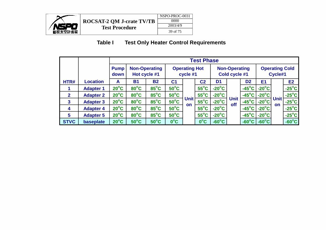
Table I Test Only Heater Control Requirements
C1 C2 E1 E21 Adapter 1 20oC 80oC 85oC 50oC 55oC -20oC -45oC -20oC -25oC2 Adapter 2 20oC 80oC 85oC 50oC 55oC -20oC -45oC -20oC -25oC3 Adapter 3 20oC 80oC 85oC 50oC 55oC -20oC -45oC -20oC -25oC4 Adapter 4 20oC 80oC 85oC 50oC 55oC -20oC -45oC -20oC -25oC5 Adapter 5 20oC 80oC 85oC 50oC 55oC -20oC -45oC -20oC -25oC
STVC baseplate 20oC 50oC 50oC 0oC 0oC -60oC -60oC -60oC -60oC
HTR# Location
Pumpdown
A
Non-OperatingHot cycle #1
Test Phase
B1 B2
Non-OperatingCold cycle #1
D1
Operating Hotcycle #1
Operating ColdCycle#1
Uniton
Uniton
Unitoff
D2
NSPO-PROC-0031 0000
2003/4/9 ROCSAT-2 QM J-crate TV/TB
Test Procedure 40 of 75
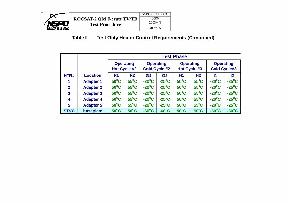
Table I Test Only Heater Control Requirements (Continued)
G1 G2 I1 I21 Adapter 1 50oC 55oC -20oC -25oC 50oC 55oC -20oC -25oC2 Adapter 2 50oC 55oC -20oC -25oC 50oC 55oC -20oC -25oC3 Adapter 3 50oC 55oC -20oC -25oC 50oC 55oC -20oC -25oC4 Adapter 4 50oC 55oC -20oC -25oC 50oC 55oC -20oC -25oC5 Adapter 5 50oC 55oC -20oC -25oC 50oC 55oC -20oC -25oC
STVC baseplate 50oC 50oC -60oC -60oC 50oC 50oC -60oC -60oC
H2
OperatingCold Cycle#3
F1 F2 H1HTR# Location
Test PhaseOperating
Hot Cycle #2Operating
Cold Cycle #2Operating
Hot Cycle #3
NSPO-PROC-0031 0000
2003/4/9 ROCSAT-2 QM J-crate TV/TB
Test Procedure 41 of 75
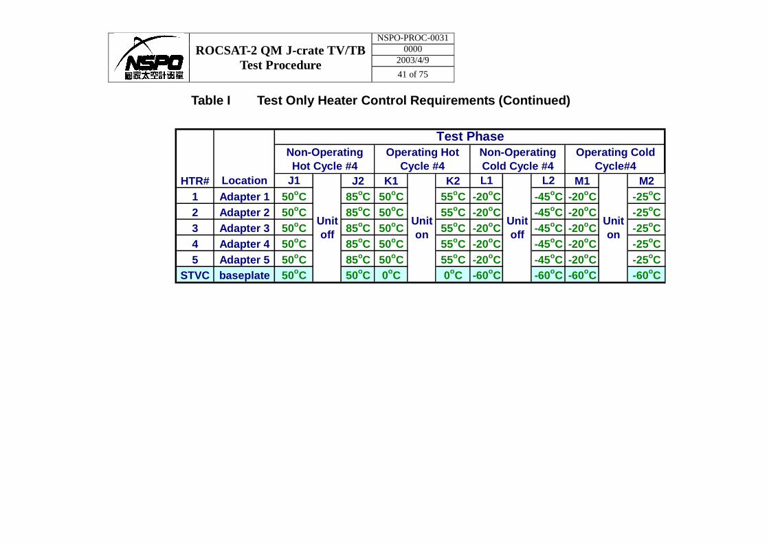
Table I Test Only Heater Control Requirements (Continued)
J2 K1 K2 M1 M21 Adapter 1 50oC 85oC 50oC 55oC -20oC -45oC -20oC -25oC2 Adapter 2 50oC 85oC 50oC 55oC -20oC -45oC -20oC -25oC3 Adapter 3 50oC 85oC 50oC 55oC -20oC -45oC -20oC -25oC4 Adapter 4 50oC 85oC 50oC 55oC -20oC -45oC -20oC -25oC5 Adapter 5 50oC 85oC 50oC 55oC -20oC -45oC -20oC -25oC
STVC baseplate 50oC 50oC 0oC 0oC -60oC -60oC -60oC -60oC
Uniton
Operating ColdCycle#4
L2
Non-OperatingHot Cycle #4
Unitoff
Uniton
Unitoff
HTR# Location
Test PhaseOperating Hot
Cycle #4Non-OperatingCold Cycle #4
J1 L1
NSPO-PROC-0031 0000
2003/4/9 ROCSAT-2 QM J-crate TV/TB
Test Procedure 42 of 75
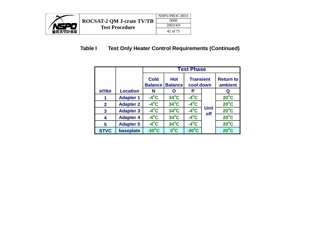
Table I Test Only Heater Control Requirements (Continued)
STVC baseplate5 Adapter 5
2 Adapter 21 Adapter 1
4 Adapter 43 Adapter 3
HTR# Location
Test Phase
ColdBalance
HotBalance
Return toambient
Transientcool down
QN O P
Unitoff
-4oC 34oC -4oC 20oC-4oC 34oC -4oC 20oC
-4oC 34oC -4oC 20oC-4oC 34oC -4oC
20oC20oC
-30oC 0oC -30oC
20oC
-4oC 34oC -4oC
NSPO-PROC-0031 0000
2003/4/9 ROCSAT-2 QM J-crate TV/TB
Test Procedure 43 of 75
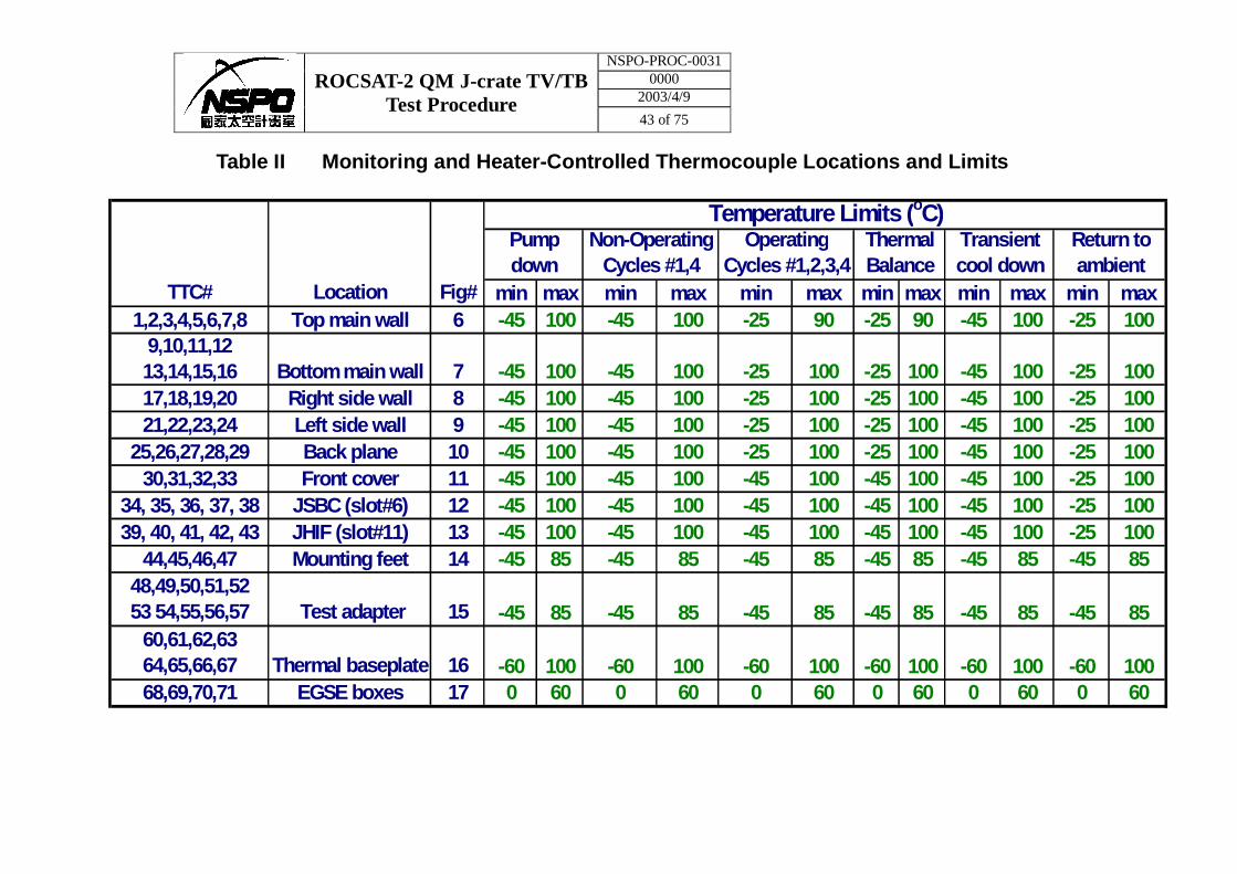
Table II Monitoring and Heater-Controlled Thermocouple Locations and Limits
min max min max min max min max min max min max1,2,3,4,5,6,7,8 Top main wall 6 -45 100 -45 100 -25 90 -25 90 -45 100 -25 100
9,10,11,1213,14,15,16 Bottom main wall 7 -45 100 -45 100 -25 100 -25 100 -45 100 -25 10017,18,19,20 Right side wall 8 -45 100 -45 100 -25 100 -25 100 -45 100 -25 10021,22,23,24 Left side wall 9 -45 100 -45 100 -25 100 -25 100 -45 100 -25 100
25,26,27,28,29 Back plane 10 -45 100 -45 100 -25 100 -25 100 -45 100 -25 10030,31,32,33 Front cover 11 -45 100 -45 100 -45 100 -45 100 -45 100 -25 100
34, 35, 36, 37, 38 JSBC (slot#6) 12 -45 100 -45 100 -45 100 -45 100 -45 100 -25 10039, 40, 41, 42, 43 JHIF (slot#11) 13 -45 100 -45 100 -45 100 -45 100 -45 100 -25 100
44,45,46,47 Mounting feet 14 -45 85 -45 85 -45 85 -45 85 -45 85 -45 85
68,69,70,71 EGSE boxes 17 0 60 0 60 0 60 0 60 0 60 0 60
TTC# Location Fig#
Temperature Limits (oC)Pumpdown
Non-OperatingCycles #1,4
OperatingCycles #1,2,3,4
ThermalBalance
Transientcool down
Return toambient
Test adapter 15 -45 85 -45 85 -45 85 -45 85 -45 85
-60 100 -60 100Thermal baseplate 16 -60 100 -60 100
48,49,50,51,5253 54,55,56,57
60,61,62,6364,65,66,67 -60 100 -60 100
-45 85
NSPO-PROC-0031 0000
2003/4/9 ROCSAT-2 QM J-crate TV/TB
Test Procedure 44 of 75
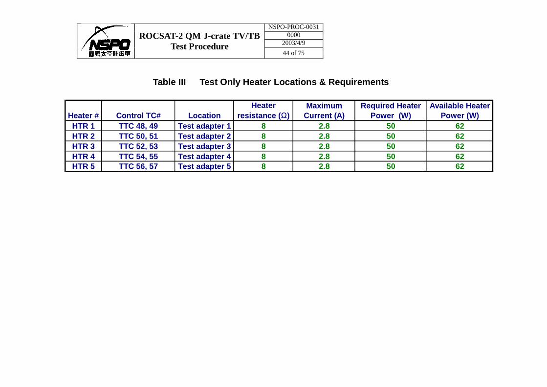
Table III Test Only Heater Locations & Requirements
HTR 1 TTC 48, 49 Test adapter 1 8 2.8 50 62HTR 2 TTC 50, 51 Test adapter 2 8 2.8 50 62HTR 3 TTC 52, 53 Test adapter 3 8 2.8 50 62HTR 4 TTC 54, 55 Test adapter 4 8 2.8 50 62HTR 5 TTC 56, 57 Test adapter 5 8 2.8 50 62
MaximumCurrent (A)
Required HeaterPower (W)
Available HeaterPower (W)Heater # Control TC# Location
Heaterresistance (Ω)
NSPO-PROC-0031 0000
2003/4/9 ROCSAT-2 QM J-crate TV/TB
Test Procedure 45 of 75
Figure 1 QM J-crate TV Test Configuration
STVC door
Thermal baseplate 1m x 1.25m (-60oC ~ 100oC)
Test adapter
QM J-crate
NSPO-PROC-0031 0000
2003/4/9 ROCSAT-2 QM J-crate TV/TB
Test Procedure 46 of 75
Figure2 QM J-crate Thermal Vacuum/ Thermal Balance Test Sequence
Thermal Balance Phase
Pump Down
Chamber Environments: Pressure≦1.0x10⁻⁵ mbar
Return To Ambient
Ambient +20oC
Hot Non-Op. +85oC
Temperature (Proto-flight Test Level)
Thermal Cycling Phase
Hot Op. +55oC
Cold Non-Op. -45oC
Cold Op. -25oC
A B C D E F G H I J K L M
2 hrs Hot soak
Hot Balance
Cold Balance
Transient Cool-Down
1 hr
1 hr 1 hr
1 hr
Operation (on) Non-operation (off)
1 hr 1 hr Turn off
Turn on
2 hrs Hot soak
2 hrs cold soak
N O P Q
2 hrs cold soak 1 hr
NSPO-PROC-0031 0000
2003/4/9 ROCSAT-2 QM J-crate TV/TB
Test Procedure 47 of 75
Figure 3 External surfaces of QM J-crate test configuration
MLI
NSPO-PROC-0031 0000
2003/4/9 ROCSAT-2 QM J-crate TV/TB
Test Procedure 48 of 75
Figure 4 Test adapter
Test adapter
QM J-crate
Thermal baseplate
Cho-Therm between J-crate and test adapter
Cho-Therm between thermal baseplate and test adapter
NSPO-PROC-0031 0000
2003/4/9 ROCSAT-2 QM J-crate TV/TB
Test Procedure 49 of 75
Figure 5 QM J-Crate Thermal Vacuum Test Electrical Test Set-up (provided by Dr. Cai from CERN)
NSPO-PROC-0031 0000
2003/4/9 ROCSAT-2 QM J-crate TV/TB
Test Procedure 50 of 75
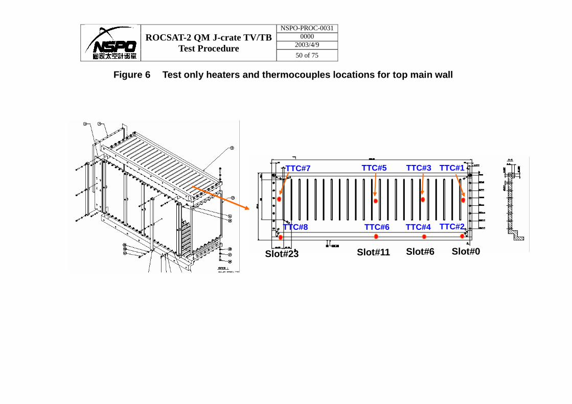
Figure 6 Test only heaters and thermocouples locations for top main wall
Slot#0 Slot#23 Slot#11 Slot#6
TTC#7
TTC#8 TTC#4
TTC#3 TTC#1
TTC#2
TTC#5
TTC#6
NSPO-PROC-0031 0000
2003/4/9 ROCSAT-2 QM J-crate TV/TB
Test Procedure 51 of 75
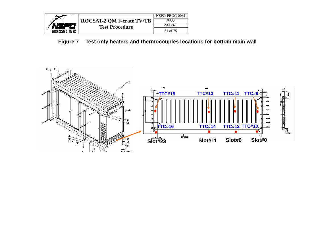
Figure 7 Test only heaters and thermocouples locations for bottom main wall
Slot#0 Slot#23 Slot#11 Slot#6
TTC#15
TTC#16 TTC#12
TTC#11 TTC#9
TTC#10
TTC#13
TTC#14
NSPO-PROC-0031 0000
2003/4/9 ROCSAT-2 QM J-crate TV/TB
Test Procedure 52 of 75
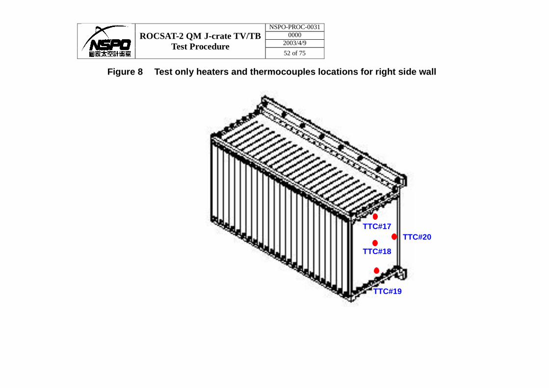
Figure 8 Test only heaters and thermocouples locations for right side wall
TTC#20
TTC#19
TTC#18
TTC#17
NSPO-PROC-0031 0000
2003/4/9 ROCSAT-2 QM J-crate TV/TB
Test Procedure 53 of 75
Figure 9 Test only heaters and thermocouples locations for left side wall
TTC#24 TTC#23
TTC#22
TTC#21
NSPO-PROC-0031 0000
2003/4/9 ROCSAT-2 QM J-crate TV/TB
Test Procedure 54 of 75
Figure 10 Test only heaters and thermocouples locations for back plane (mother board)
TTC#25 TTC#27
TTC#26
TTC#29
TTC#28
NSPO-PROC-0031 0000
2003/4/9 ROCSAT-2 QM J-crate TV/TB
Test Procedure 55 of 75
Figure 11 Test only heaters and thermocouples locations for front cover
TTC#31
TTC#33
TTC#30
TTC#32
NSPO-PROC-0031 0000
2003/4/9 ROCSAT-2 QM J-crate TV/TB
Test Procedure 56 of 75
Figure 12 Test only heaters and thermocouples locations for JSBC (SLOT#6)
Wedge-lock (facing side)
PCB (bottom surface near DALLAS sensor )
Near spacer (bottom surface)
Heat sink
PCB (bottom surface) TTC#38
TTC#37
TTC#36
TTC#35
TTC#34
NSPO-PROC-0031 0000
2003/4/9 ROCSAT-2 QM J-crate TV/TB
Test Procedure 57 of 75
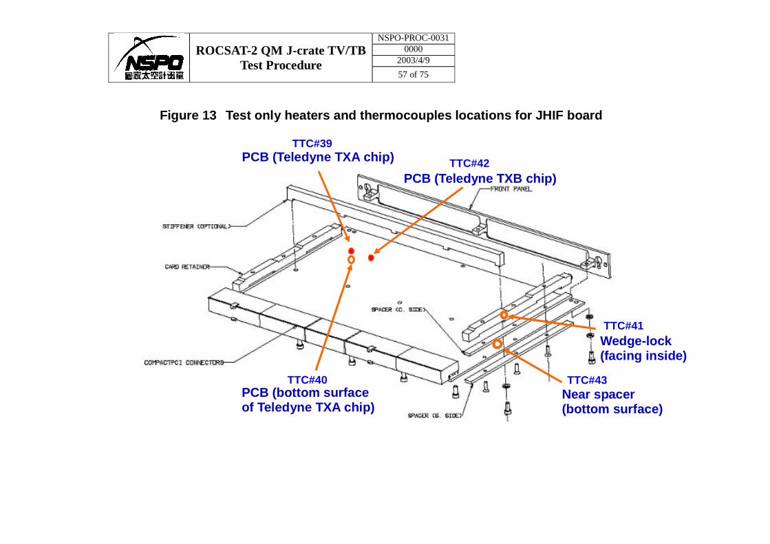
Figure 13 Test only heaters and thermocouples locations for JHIF board
Wedge-lock (facing inside)
PCB (Teledyne TXA chip)
Near spacer (bottom surface)
PCB (Teledyne TXB chip)
PCB (bottom surface of Teledyne TXA chip)
TTC#40
TTC#41
TTC#42
TTC#43
TTC#39
NSPO-PROC-0031 0000
2003/4/9 ROCSAT-2 QM J-crate TV/TB
Test Procedure 58 of 75
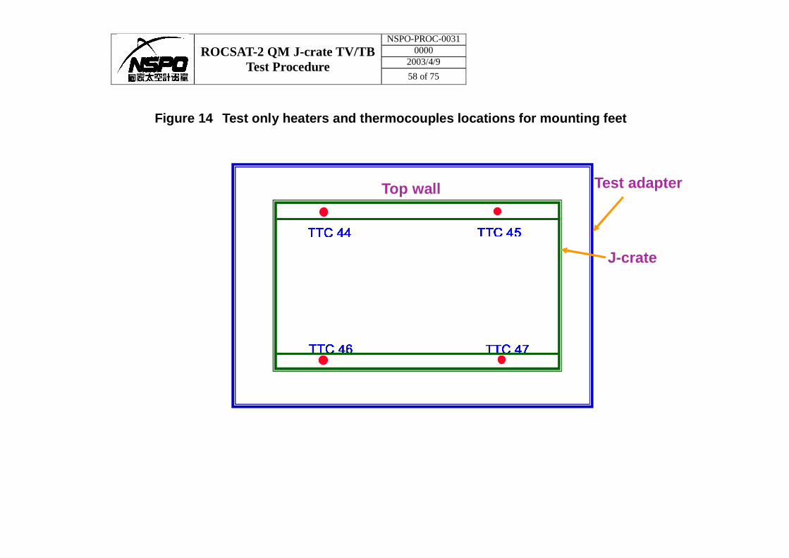
Figure 14 Test only heaters and thermocouples locations for mounting feet
TTC 44 TTC 45
TTC 46 TTC 47
Top wall Test adapter
J-crate
NSPO-PROC-0031 0000
2003/4/9 ROCSAT-2 QM J-crate TV/TB
Test Procedure 59 of 75
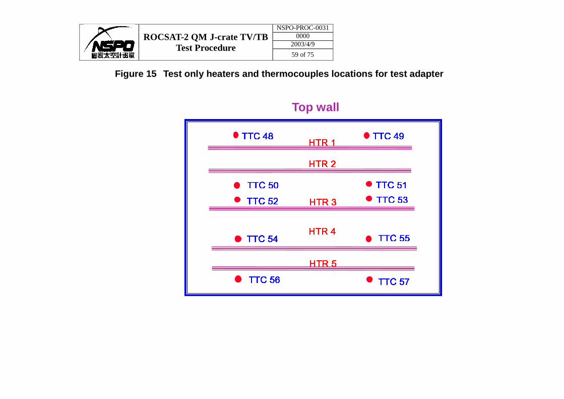
Figure 15 Test only heaters and thermocouples locations for test adapter
TTC 48HTR 1
HTR 2
HTR 3
TTC 49
TTC 50 TTC 51
TTC 52 TTC 53
TTC 56 TTC 57
TTC 54 TTC 55HTR 4
HTR 5
Top wall
NSPO-PROC-0031 0000
2003/4/9 ROCSAT-2 QM J-crate TV/TB
Test Procedure 60 of 75
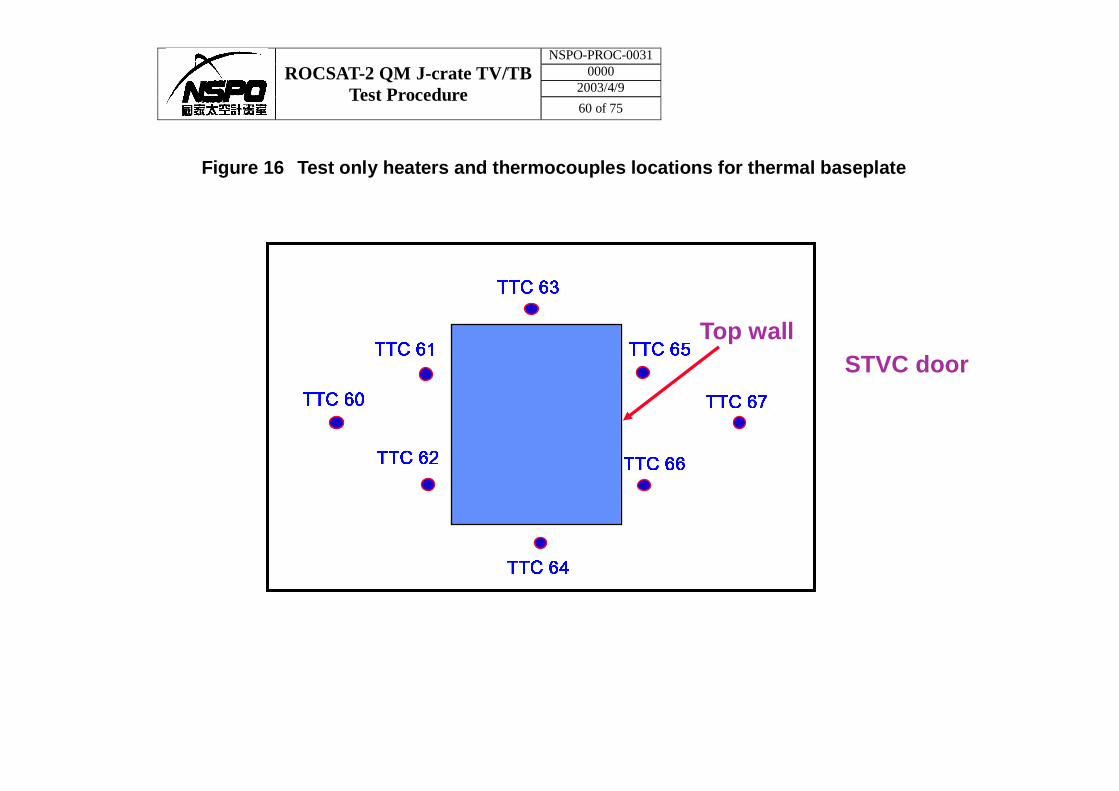
Figure 16 Test only heaters and thermocouples locations for thermal baseplate
TTC 63
TTC 65
TTC 62
TTC 61
TTC 60 TTC 67
TTC 64
TTC 66
Top wall STVC door
NSPO-PROC-0031 0000
2003/4/9 ROCSAT-2 QM J-crate TV/TB
Test Procedure 61 of 75
Figure 17 Test only heaters and thermocouples locations for EGSE boxes
TTC 68 TTC 69 TTC 70 TTC 71
EGSE box #1 EGSE box #2 EGSE box #3 EGSE box #4
NSPO-PROC-0031 0000
2003/4/9 ROCSAT-2 QM J-crate TV/TB
Test Procedure 62 of 75
APPENDIX A
CUSTODIAL TEST EQUIPMENT LISTING
(CTE)
NSPO-PROC-0031 0000
2003/4/9 ROCSAT-2 QM J-crate TV/TB
Test Procedure 63 of 75
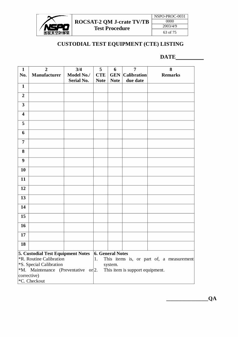
CUSTODIAL TEST EQUIPMENT (CTE) LISTING
DATE
1 No.
2 Manufacturer
3/4 Model No./ Serial No.
5 CTE Note
6 GEN Note
7 Calibration
due date
8 Remarks
1
2
3
4
5
6
7
8
9
10
11
12
13
14
15
16
17
18
5. Custodial Test Equipment Notes *R. Routine Calibration *S. Special Calibration *M. Maintenance (Preventative or corrective) *C. Checkout
6. General Notes 1. This items is, or part of, a measurement
system. 2. This item is support equipment.
_______________QA

NSPO-PROC-0031 0000
2003/4/9 ROCSAT-2 QM J-crate TV/TB
Test Procedure 64 of 75
APPENDIX B
Test Procedures for J-Crate (QM) Environmental Tests

NSPO-PROC-0031 0000
2003/4/9 ROCSAT-2 QM J-crate TV/TB
Test Procedure 65 of 75
Test Procedures for J-Crate (QM) Environmental Tests
Version 2.0
November 11, 2002
1. Scope
This document is to specify the test procedures of all environmental tests for qualification modules (QM) of AMS-02 J-crate. The purpose of the test is to qualify the J-crate for use in a space environment.
The J-crate is specified by the design requirement document (rev. 6) and specification for each board. The interface details and functional test details are described in separate documents.
2. Software in J-Crate
There are four main DAQ computers (JMDC) in J-crate. They can be powered independently. Each JMDC has a single board computer (JSBC), a data buffer (JBU), an AMSWire and 1553 interface (JIM-AMSW/1553), a high rate data interface (JIM-HRDL/422) and an internal slow control interface (JIM-CAN). They are connected together by Compact-PCI bus.
The high rate data interface can use either fiber optical signals or synchronous RS422 signals. Both types of high rate data signals are interfaced by a single module (JHIF) to the outside. Only one link can be used at a time. Therefore, they cannot be tested in the same.
During the tests, each JMDC is running independently. The JDMC software have two parts, ROM monitor and test software. The ROM monitor processes only the startup related task. For test, it will load default test software from flash memory automatically after start up initializations when power is on. The special procedure will be described in appendix for download and boot new test software.
The test software is based on Hardhat Linux 2.4.2 operating system kernel. The operating system, test applications and configuration files are packed into one image file and stored into flash memory. ROM monitor will load the package from the flash memory and start its self-unpack and startup process. After the operating system starts, it will load all the device drivers and test applications automatically. The test applications will run according to the default configuration files stored in the package. Changing of the configuration files is possible only with a new test software package being loaded to the system. A few of the configuration values can be changed by commanding the system.
The services running on JMDC and related hardware are listed in the Table 1. Where, the master and slave is the meaning of the JMDC actions. The details about echo test, HK data report and command requests functions are described in J-crate functional tests document.
NSPO-PROC-0031 0000
2003/4/9 ROCSAT-2 QM J-crate TV/TB
Test Procedure 66 of 75
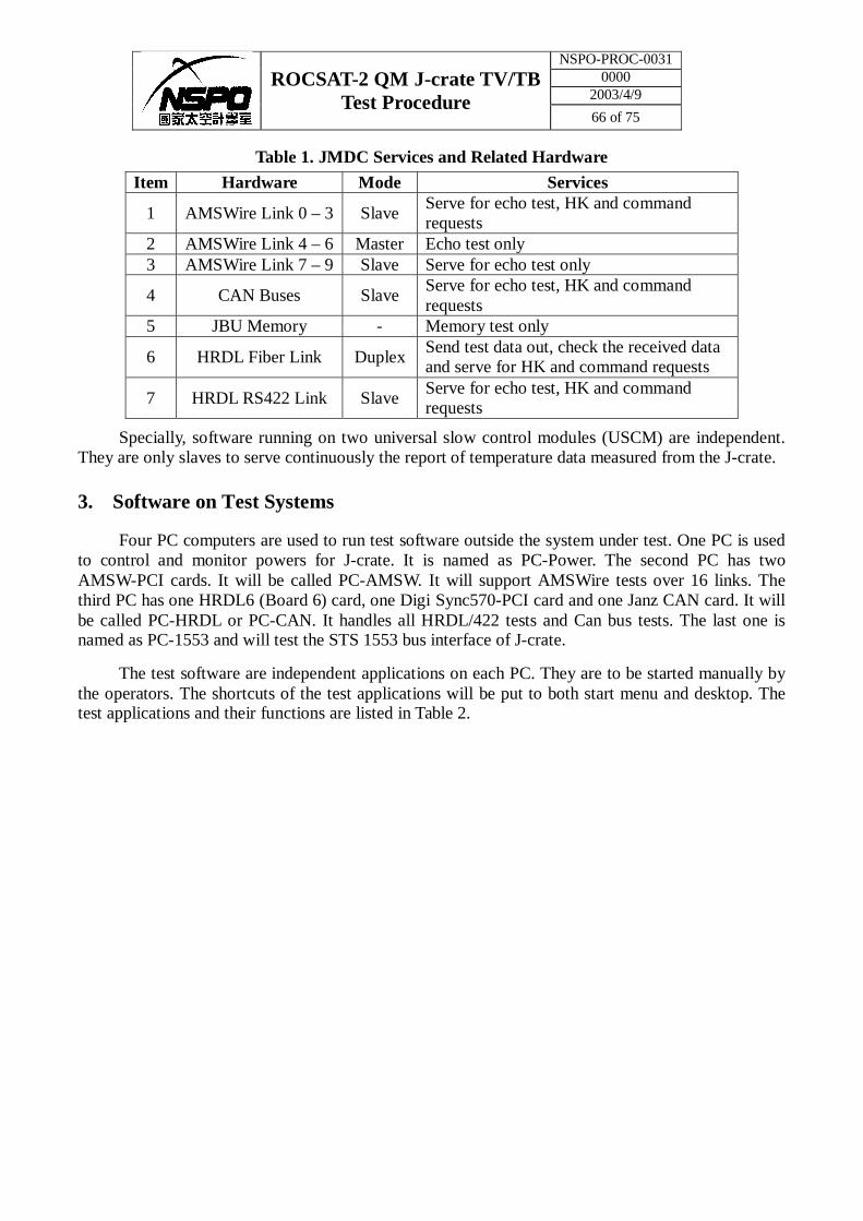
Table 1. JMDC Services and Related Hardware
Item Hardware Mode Services
1 AMSWire Link 0 – 3 Slave Serve for echo test, HK and command requests
2 AMSWire Link 4 – 6 Master Echo test only 3 AMSWire Link 7 – 9 Slave Serve for echo test only
4 CAN Buses Slave Serve for echo test, HK and command requests
5 JBU Memory - Memory test only
6 HRDL Fiber Link Duplex Send test data out, check the received data and serve for HK and command requests
7 HRDL RS422 Link Slave Serve for echo test, HK and command requests
Specially, software running on two universal slow control modules (USCM) are independent. They are only slaves to serve continuously the report of temperature data measured from the J-crate.
3. Software on Test Systems
Four PC computers are used to run test software outside the system under test. One PC is used to control and monitor powers for J-crate. It is named as PC-Power. The second PC has two AMSW-PCI cards. It will be called PC-AMSW. It will support AMSWire tests over 16 links. The third PC has one HRDL6 (Board 6) card, one Digi Sync570-PCI card and one Janz CAN card. It will be called PC-HRDL or PC-CAN. It handles all HRDL/422 tests and Can bus tests. The last one is named as PC-1553 and will test the STS 1553 bus interface of J-crate.
The test software are independent applications on each PC. They are to be started manually by the operators. The shortcuts of the test applications will be put to both start menu and desktop. The test applications and their functions are listed in Table 2.
NSPO-PROC-0031 0000
2003/4/9 ROCSAT-2 QM J-crate TV/TB
Test Procedure 67 of 75
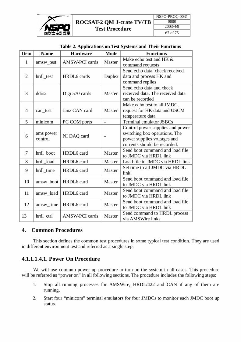
Table 2. Applications on Test Systems and Their Functions
Item Name Hardware Mode Functions
1 amsw_test AMSW-PCI cards Master Make echo test and HK & command requests
2 hrdl_test HRDL6 cards Duplex Send echo data, check received data and process HK and command replies
3 ddrs2 Digi 570 cards Master Send echo data and check received data. The received data can be recorded
4 can_test Janz CAN card Master Make echo test to all JMDC, request for HK data and USCM temperature data
5 minicom PC COM ports - Terminal emulator JSBCs
6 ams power control
NI DAQ card -
Control power supplies and power switching box operations. The power supplies voltages and currents should be recorded.
7 hrdl_boot HRDL6 card Master Send boot command and load file to JMDC via HRDL link
8 hrdl_load HRDL6 card Master Load file to JMDC via HRDL link
9 hrdl_time HRDL6 card Master Set time to all JMDC via HRDL link
10 amsw_boot HRDL6 card Master Send boot command and load file to JMDC via HRDL link
11 amsw_load HRDL6 card Master Send boot command and load file to JMDC via HRDL link
12 amsw_time HRDL6 card Master Send boot command and load file to JMDC via HRDL link
13 hrdl_ctrl AMSW-PCI cards Master Send command to HRDL process via AMSWire links
4. Common Procedures
This section defines the common test procedures in some typical test condition. They are used in different environment test and referred as a single step.
4.1.1.1. 4.1. Power On Procedure
We will use common power up procedure to turn on the system in all cases. This procedure will be referred as “power on” in all following sections. The procedure includes the following steps:
1. Stop all running processes for AMSWire, HRDL/422 and CAN if any of them are running.
2. Start four “minicom” terminal emulators for four JMDCs to monitor each JMDC boot up status.
NSPO-PROC-0031 0000
2003/4/9 ROCSAT-2 QM J-crate TV/TB
Test Procedure 68 of 75
3. Start a terminal on PC-HRDL to be ready for sending “time” command.
4. Turn on AC for all power supplies and power switching box.
5. Set power switches for JFOM-A, JLIF and USCM to position “on”.
6. Set switches for the JMDCs you would like to turn on to position “on”.
7. Use software to turn on the power supplies together.
8. Watch all JMDCs boot status in minicom.
9. When ROM monitor initialization has finished, using “hrdl_time” command on PC-HRDL to all JMDCs.
4.1.1.2. 4.2. Power Off Procedure
The power down is also a common procedure for all cases. It will be referred as “power off” in the following sections. The steps are as below.
1. Use software on PC-Power to turn off DC of all power supplies together.
2. Stop to record valtages and currents.
3. Stop CAN test program on PC-CAN.
4. Stop amsw_test program on PC-AMSW.
5. Stop hrdl_test program or ddrs2 program on PC-HRDL.
4.1.1.3. 4.3. Switching HRDL and RS422 links
There are four parts of high rate data interface, JFOM-A, JFOM-B, J422-A and J422-B in J-crate. The JFOM-A, JFOM-B and J422 are not powered at the same time. Two RS422 links are powered together but only one of them can transmit data. There are special procedures to switch these links.
The procedure is to specify the test for different parts of high rate interface. It is referred as “HRDL switching”. The switching time is related on the requirements of environmental tests. They will be defined later in this document. The switching steps are listed as following.
6. All JMDCs will be started in HRDL RX mode only by default after power is on.
7. Use “hrdl_ctrl” program on PC-AMSW to enable the HRDL TX on the first JMDC.
8. When HRDL switching time reached, use “hrdl_ctrl” to disable HRDL TX on the first JMDC and then enable the TX on the second JMDC.
9. Repeat step 3 for all JMDCs which are powered.
10. After the last JMDC has been tested with JFOM-A, change JFOM-A power switch to “off” state and then switch on JFOM-B. The loopback test will continue on this JMDC. The PC-HRDL stop receiving data.
11. Stop “hrdl_test” program on PC-HRDL.
12. At HRDL switching time, use “hrdl_ctrl” to disable current HRDL TX and enable the HRDL TX for the next JMDC.
NSPO-PROC-0031 0000
2003/4/9 ROCSAT-2 QM J-crate TV/TB
Test Procedure 69 of 75
13. Repeat step 7 until the last JMDC.
14. After the last JMDC, use “hrdl_ctrl” to set all JMDCs to RS422 receiving mode only.
15. Switch off JFOM-B and switch on J422 power.
16. Connect Digi570 cable to J422-A box.
17. Start “ddrs2” program on PC-HRDL.
18. Use “hrdl_ctrl” to enable RS422 TX on the first JMDC.
19. Like HRDL part, disable previous JMDC TX and enable the next until the last JMDC.
20. Change Digi570 cable to J422-B box.
21. Repeat step 14 for check J422-B.
22. Switch off J422 power.
23. The step 2 – 17 can be repeated as many times as you want, but before going back to step 2, you have to use “hrdl_ctrl” to set all JMDC in HRDL RX mode and then switch on JFOM-A power.
4.1.1.4. 4.4. Power-on Test Procedure
The processors booting is the most difficult step during system powered on especially for the temperature cycles and thermal-vacuum test. It is important to make special tests on this part. The steps are listed here.
24. Power on
25. Watch all four JMDC’s booting status until all test applications started in all JMDCs.
26. Power off
27. Wait for about 1 min.
28. Repeat 3 – 5 times of step 1 – 4. The test can be ended at the power on stage (step 2) to continue four JMDCs tests.
4.1.1.5. 4.5. Test Procedure for JMDCs
This section specifies the procedure for test JMDCs. The number of JMDCs under test can be 1 to 4. When four JMDCs are testing together, it may be dangerous at the high temperature and should take special care this case. We will limit maximum running time for this situation to 20 min. at high temperature.
The following items will be done for the test. The HRDL switching time can be calculated by the total test time divided by 4 and the divided by number of JMDCs under test.
29. Power on or continue of power-on test.
30. Start amsw_test on PC-AMSW.
NSPO-PROC-0031 0000
2003/4/9 ROCSAT-2 QM J-crate TV/TB
Test Procedure 70 of 75
31. Start hrdl_test on PC-HRDL
32. Start CAN test program on PC-CAN to make “echo” test with JMDCs and read temperature data fromUSCMs.
33. Using hrdl_ctrl program on PC-AMSW to turn on TX for the first JMDC which is on.
34. Switching HRDL according to the HRDL switching time defined.
35. The test continues until the total test time reached.
36. Power off or continue with other tests.
5. Environmental Test Procedures
The AMS-02 J-crate environmental tests has following items:
37. Temperature cycles.
38. Vibration test
39. Electro-Magnetic Interference (EMI) test
40. Thermal Vacuum Test
Since they have different test requirements, we will use different test procedure during each test. They are described in the following sections.
5.1.1.1. 5.1. Vibration Test Procedure
The vibration test will be done for three directions. The total test time for each direction is about 10 min. Since time is short, there will be no time to switch JMDCs. In order to test all JMDCs in during the vibration, we will use the test procedure for four JMDCs here and the vibration should start only when all test applications are started (step 4).
The test will not be stopped until the vibration is stopped.
41. Power on before vibration started
42. Start test for four JMDCs
43. Power off after vibration stopped.
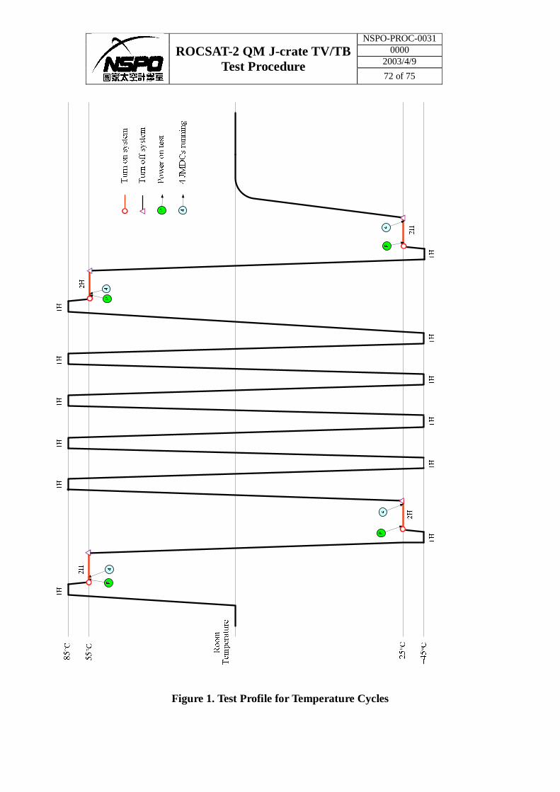
5.1.1.2. 5.2. Temperature Cycles
The temperature cycles will use the test profile shown in Figure 1. The functional test will be in the first 2 – 4 cycles and the last 2 – 4 cycles. The middle cycles will run without functional tests. Each functional test time is about 1 - 2 hours.
Since the worst case is different in the high and low temperature stages, the test procedures will be different in these two cases. The test procedure at the high temperature is the following.
44. Power-on test should be at the beginning.
45. Continue with four JMDCs test for 10 – 20 min.
NSPO-PROC-0031 0000
2003/4/9 ROCSAT-2 QM J-crate TV/TB
Test Procedure 71 of 75
46. Power off
47. Power on with two JMDCs. The first high and low stages start with group A first and the next high and low stages start with group B.
48. Test two JMDCs together. The group testing time is about one hour.
49. Power off
50. Power on the other group of JMDCs.
51. Repeat step 5 – 7 until the end of test.
52. Power off.
The test procedure at the low temperature is specified as the following.
53. Power-on test should be at the beginning.
54. Continue with two JMDCs test as specified for high temperature stage.
55. At the last 10 – 20 min. power off.
56. Power on with four JMDCs
57. Start four JMDCs test until the end.
58. Power off.
5.1.1.3. 5.3. Electro-Magnetic Interference (EMI) Test
The EMI test consists of a lot of short tests to test different items. Each test will last about 20 – 30 min. The worst case is to running all four JMDCs. Therefore we will use the test procedure for four JMDCs during the whole test period.
59. Power on.
60. Start four JMDCs test.
61. Power off.
NSPO-PROC-0031 0000
2003/4/9 ROCSAT-2 QM J-crate TV/TB
Test Procedure 72 of 75
Figure 1. Test Profile for Temperature Cycles
NSPO-PROC-0031 0000
2003/4/9 ROCSAT-2 QM J-crate TV/TB
Test Procedure 73 of 75
5.1.1.4. 5.4. Thermal Vacuum Test
The thermal vacuum test profile is shown in Figure 2. The functional test time is much longer than the temperature cycles. But it still has the different worst case at high and low temperature as temperature cycles.
The tests at both high temperature and low temperature will be the same as the temperature cycles. There will be no special tests during the middle cycles. The test for two JMDCs will run alternatively for two groups until the specified stop time.
In the cold and hot balance test, we will use only JMDC 1 for test and no HRDL switch during this test.
62. Power-on JMDC 1.
63. Start one JMDC test procedure nothing to touch again until the end of test.
64. Power off.
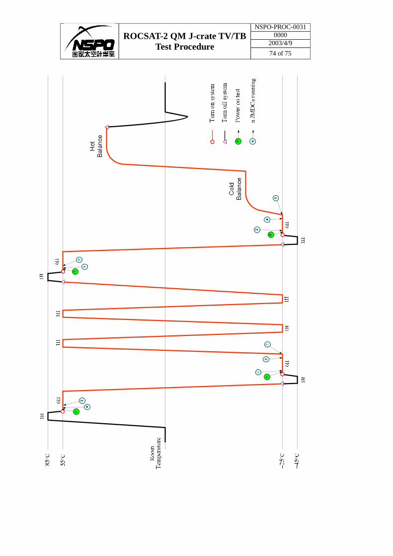
NSPO-PROC-0031 0000
2003/4/9 ROCSAT-2 QM J-crate TV/TB
Test Procedure 74 of 75
NSPO-PROC-0031 0000
2003/4/9 ROCSAT-2 QM J-crate TV/TB
Test Procedure 75 of 75
Figure 2. Thermal-Vacuum Test Profile
5.1.2. Appendix A. Procedure to Load New Programs
The boot command with file load will follow the steps in below.
65. Power off all JMDCs.
66. Stop “amsw_test” on PC-AMSW
67. Stop “hrdl_test” on PC-HRDL
68. Stop “can_test” on PC-CAN
69. Power on the JMDC you want to boot and JFOM-A.
70. After JMDC start to wait for time, use “hrdl_boot” to reboot JMDC and send file to JDMC.
The “hrdl_boot” software has options to select JMDC number, to choose file, flag for save file to flash and to choose the flash number (0 – 7).
5.1.3. Appendix B. Check List for Vibration Test
(add later)
5.1.4. Appendix C. Check List for Temperature Cycles
(add later)
5.1.5. Appendix B. Check List for EMI Test
(add later)
5.1.6. Appendix B. Check List for Thermal-Vacuum Test
(add later)

![AMS GIAU YES O AUSAIA YMEOEA III/media/Documents/QM/About+Us/...AMS GIAU YES O AUSAIA YMEOEA III ^57 a eso [= Gooae] Q ue 1913 a a i i uy QM cas o seaae is a sies as oows Ca 1 - 1](https://img.pdfslide.us/doc/110x75/60b3aac0b290a712027ea813/ams-giau-yes-o-ausaia-ymeoea-iii-mediadocumentsqmaboutus-ams-giau-yes-o.jpg)


![AMS GIAU YES O AUSAIA YMEOEA III - Queensland Museum/media/Documents/QM/About+Us/Publications/... · AMS GIAU YES O AUSAIA YMEOEA III ^57. a eso [= Gooae] Q ue 1913 a a i i uy. QM](https://img.pdfslide.us/doc/110x75/5aa06ad17f8b9a7f178e0e76/ams-giau-yes-o-ausaia-ymeoea-iii-queensland-mediadocumentsqmaboutuspublicationsams.jpg)


![AMS GIAU YES O AUSAIA YMEOEA II - Queensland Museum/media/Documents/QM/About+Us/Publications/... · AMS GIAU YES O AUSAIA YMEOEA II ^11. wig "S Aus" "hr b/l. Giau 9 [G1-1]" QM 1 sage](https://img.pdfslide.us/doc/110x75/5aa06a057f8b9a84178e1d45/ams-giau-yes-o-ausaia-ymeoea-ii-queensland-mediadocumentsqmaboutuspublicationsams.jpg)