Embed Size (px)
Citation preview

NATIONAL (NATO) STOCK NUMBER: NSN 6530-01-265-3583
THE
OREGON™ SPINE SPLINT II (OSS™ II)
INSTRUCTIONS
The spinal immobilizer designed for VEHICLE EXTRICATION and for use with the SKED® STRETCHER, backboards or other patient transport devices.
(07-04)
OREGON™ SPINE SPLINT II INSTRUCTIONS Page 2
INSTRUCTIONS FOR USE OF OREGON™ SPINE SPLINT II
I. INTRODUCTION - A WORD OF CAUTION
The Oregon™ Spine Splint II is a professional devicedesigned to be used by properly trained and certified pre-hospital and hospital Emergency Medical personnel. Thedevice should only be used by Emergency MedicalTechnicians (EMT’s) or others properly trained and certifiedin the considerations and management of Spine Trauma,who operate under proper Medical Control or under themedical supervision of a Physician Medical Director.
WARNING: Use by persons without proper previous training can present a danger to the patientresulting in permanent spine damage or other critical conditions and should not be attempted.The instructions furnished here are for the use of properly trained Emergency Medical person-nel and serve as guidelines. The exact method of use and indication and contraindication foruse must be determined by the service’s Medical Director or other local pre-hospital medicalauthority.
The Oregon™ Spine Splint II, like all similar equipment, is designed to accommodate a widerange of varying sizes and proportions throughout the range of normally expected adult anato-my. It does not assume extremely large or obese sizes beyond the classical range, nor is itdesigned for pediatric size ranges or adults who more closely approximate pediatric sizes. Itshould also not be used on persons with chronic extreme spine shapes or irregularities.

Page 3 OREGON™ SPINE SPLINT II INSTRUCTIONS
II. GENERAL CONSIDERATIONS
The Oregon™ Spine Splint II is a vest-type device which is designed - when properly used in con-junction with a properly fitting, effective cervical collar- to provide immobilization for a patient in a sittingor supine position, or a patient in a complex rescue situation where the physical environment makes it
impossible or dangerous to apply a long spineboard orequivalent immediately. The device, as are all vest-type or“half-board” devices, is designed solely to offer adequateimmobilization from a sitting position until the patient canbe placed onto a suitable long spineboard (or other rescuelong device such as a SKED® STRETCHER or stokes lit-ter). Proper full-body spine immobilization can NOT beachieved using any “sitting” half-board device. TheOregon™ Spine Splint II, like other vests, is designed tobe used to move the victim onto a rigid longboard (or
equivalent). Ensuring proper immobilization prior to transport requires that the patient and theOregon™ Spine Splint II be also immobilized to such a longboard (or equivalent).
When immobilizing a patient, understanding of a general sequential overview is of key importance,regardless of which device is employed. These general concepts should be followed and focused uponso that they are not lost in the detail of specific straps, etc.
General Considerations For Application Of A Device To A Sitting Patient:
1st - Assure safety of the scene and situation.
2nd - Unless contraindicated, position the patient’s head in the neutral inline position and manuallyImmobilize. Maintain the manual immobilization until the device has been completely applied.
3rd - Assess the patient’s ABC’s and provide key intervention as needed. Evaluate whether the patient’scondition allows time for the use of an interim device, or demands speedy placement with manual immo-bilization directly onto a longboard using an accepted technique for Rapid Extrication.
4th - Check MSC x 4 (Motor function, Sensory response and Circulation in all four extremities).
5th - Apply a properly fitting, effective, cervical collar.
IF TIME ALLOWS USE OF AN INTERIM DEVICE:
6th - Prepare and install the device properly behind the patient, and hold it in the proper anatomical posi-tion at the patient’s posterior torso.
7th - Fasten the device to the patient’s torso, so that it cannot move up-and-down on the torso or left-and-right at either the upper or lower torso.
8th - Readjust all torso straps/parts as needed for proper overall immobilization of the device to the torsoand of the patient in the device. Make sure that this immobilization does not restrict circulation or prop-er chest excursion.
This readjustment must be done prior to fastening the patient’s headto the device. If the torso straps are readjusted after the head isimmobilized to the device, movement of the device when adjustingthe straps will result in movement of the head and possibly com-pression or movement of the cervical vertebrae.

OREGON™ SPINE SPLINT II INSTRUCTIONS Page 4
9th - Pad behind the patient’s head as needed to fill the void between the back of the head (when in aneutral position) and the device, to ensure maintenance of the neutral in-line position when the headstraps are later applied.
10th - Immobilize the head to the device. Without losing manual in-line support of the head, place thelateral head support pieces (flaps, pads, pillows, or blanket - depending on the device) against the lat-eral flat planes of the patient’s head, and either:
a) fasten the Forehead Restraint Strap first and then fasten a strap across the cervical collar
or
b) fasten the head to the device with tape (3” adhesive tape, Colban, Medi-Rip, etc.) by wrapping firstaround the forehead to include the anterior part of the supraorbital ridge, then four or five times aroundthe forehead and upper head, and finally around the cervical collar and neck portion or the device.
Check to assure that the patient’s vision and respiration are notimpaired and that the patient’s mouth can open or be opened withease should vomiting later occur.
WARNING: Use of anything that acts as a chin cup or seats themolars - holding the mouth closed -is CONTRAINDICATED and, ifvomiting occurs, can be fatal.
11th - Recheck the patient’s ABC’s and Motor, Sensory and Circulation in all four extremities.
12th - Place patient on long spineboard and secure patient and device to the board. Position a longspineboard (or equivalent) adjacent to the patient and rotate the patient onto it (or, if not possible, lift thepatient and the device together onto the longboard. Position the patient/device correctly on the longspineboard, lower the patient’s legs, tie his feet and ankles together, and immobilize the patient/deviceto the longboard in the prescribed manner. Use additional padding and support as needed to packagethe patient before beginning transportation. Periodically re-check the patient’s ABC’s and MSC’s. If thegroin straps loosen when laying the patient down, be sure to tighten them before transporting the patient.
The specific steps for application of the Oregon™ Spine Splint II (or any device for a sitting patient)should be in keeping with these general concepts and should follow this basic sequence. These guide-lines and general sequence should be fully understood and learned. The long detailed list of substepsfor the use of a particular device is presented to introduce the EMT to the proper itemized use of thedevice. Once the EMT is familiar with all of the steps, memorization of the detailed list is unnecessaryand impractical. Knowledge of a more general sequence will cause the correct substeps to occur logi-cally.
WARNING: Application of any device to a patient should ONLY bedone by personnel fully familiar with the device and only afterrepeated supervised practice on a “mock” patient. Only after EMTpersonnel have successfully demonstrated their ability to apply thedevice to the required level of competence in a skill station and havebeen cleared by the Medical Director or a suitable EMS Instructorshould the device be placed in service for use on patients.

Page 5 OREGON™ SPINE SPLINT II INSTRUCTIONS
WARNING: The Oregon™ Spine Splint II is designed for use with a properfirm or rigid cervical collar. Both use of the Oregon™ Spine Splint II andapplication of a cervical collar require, as a prerequisite, that the patient’s headbe in a neutral in-line position. In cases when placing the patient’s head in aneutral in-line position is contraindicated and his head must be maintained inanother position, use of a cervical collar and/or the Oregon™ Spine Splint IIIS ALSO CONTRAINDICATED and would be extremely dangerous.
For situations where moving patients into a neutral in-line position is contraindicated, check with your Instructor orMedical Director. They may wish to reference a source text, such as PRE-HOSPITAL TRAUMA L/FE SUPPORTTEXT by the PHTLS Committee of the National Association of Emergency Medical Technicians In CooperationWith The Committee On Trauma Of The American College Of Surgeons; Butman and Paturas, General Editors;Emergency Training© 1986, Akron, Ohio; chapters 9 & 10.
III. GUIDELINES FOR APPLICATION OF THE OREGON™ SPINE SPLINT II
Color Coded Straps and BucklesThe Oregon™ Spine Splint’s shoulder, mid-torso, andgroin straps are color-coded for ease of identification.When used in the normal manner, each strap will fas-ten to a strap of the same color (orange to orange,green to green, gray to gray, and black to black).
• One shoulder cross strap is orange and the other isgreen.
• The mid-torso straps are gray and the male andfemale parts of the upper torso straps have whitebuckle parts and the lower torso straps have blackbuckle parts.
• The groin straps are black. The left pair of groinstraps has white buckle parts and the right pair hasblack buckle parts.
BucklesEach pair of straps fastens with a positive-fastening quick-clip buckle. One matching strap has a “male”end which can be recognized by its three prongs. The other matching strap has a”female”end whichcan be recognized as a hollow receiver. The buckles are fastened by inserting the male end into thefemale receiver until a positive click is felt as the prongs of the male buckle lock into place.
The shoulder straps have a length adjustment ability on both the male and female parts of the buckle,allowing the closed buckle to be positioned in the best anatomical location for each patient. The torsostraps and groin loops have a pre-set fixed length at the female part of the buckle, and can be adjustedto the varying girth of different patients at the male buckle part only.
Head StrapsThe head straps are easily identified, since they are detachable, short and are the only straps withoutbuckles. They fasten at each side of the head with Velcro. The upper strap, (Forehead Restraint Strap)has a replaceable forehead pad (Dispos-A-Pad) on it. The lower strap (Collar Strap), has two blackbands to go across the cervical collar.
OREGON™ SPINE SPLINT II INSTRUCTIONS Page 6
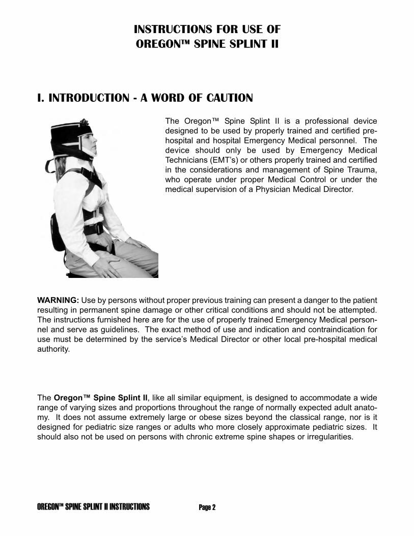
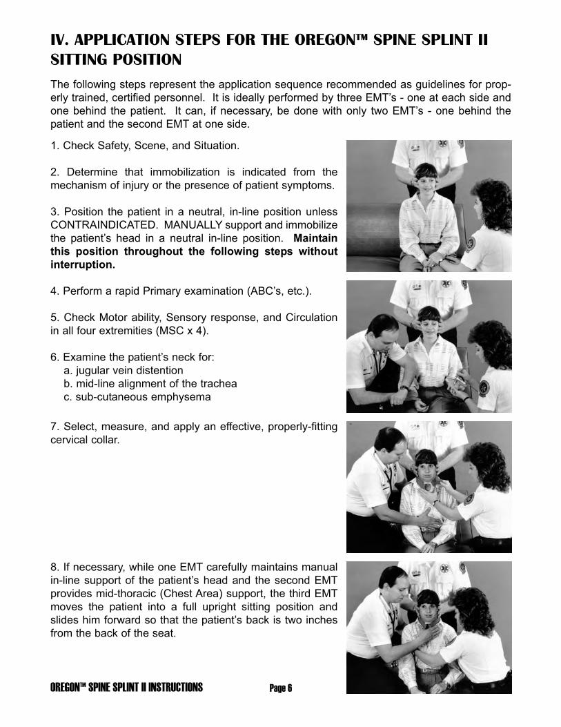
IV. APPLICATION STEPS FOR THE OREGON™ SPINE SPLINT IISITTING POSITIONThe following steps represent the application sequence recommended as guidelines for prop-erly trained, certified personnel. It is ideally performed by three EMT’s - one at each side andone behind the patient. It can, if necessary, be done with only two EMT’s - one behind thepatient and the second EMT at one side.
1. Check Safety, Scene, and Situation.
2. Determine that immobilization is indicated from themechanism of injury or the presence of patient symptoms.
3. Position the patient in a neutral, in-line position unlessCONTRAINDICATED. MANUALLY support and immobilizethe patient’s head in a neutral in-line position. Maintainthis position throughout the following steps withoutinterruption.
4. Perform a rapid Primary examination (ABC’s, etc.).
5. Check Motor ability, Sensory response, and Circulationin all four extremities (MSC x 4).
6. Examine the patient’s neck for:a. jugular vein distentionb. mid-line alignment of the tracheac. sub-cutaneous emphysema
7. Select, measure, and apply an effective, properly-fittingcervical collar.
8. If necessary, while one EMT carefully maintains manualin-line support of the patient’s head and the second EMTprovides mid-thoracic (Chest Area) support, the third EMTmoves the patient into a full upright sitting position andslides him forward so that the patient’s back is two inchesfrom the back of the seat.

Page 7 OREGON™ SPINE SPLINT II INSTRUCTIONS
9. Remove the Oregon™ Spine Splint II from its case.Open the white Velcro fastener which holds the two centerslats together and unfold the two center sections until theyare inline. Remove the head straps and place them on theseat or otherwise close at hand. The torso flaps remain fas-tened together to contain all of the other straps for ease ofinsertion behind the patient. Hold the vest by the still-fastened torso flaps.
10. With the back side of the OSS II (the side containing thesewn straps and handles) facing away from the patient’sback, hold the OSS II with its lower end below the level ofthe seat. Insert the OSS II on an angle, head end first,between the arms of the EMT holding the patient’s head(EMT behind the patient).
Bring the OSS II up into place at the patient’s back andstraighten it, so that the midline of the OSS II is at the mid-line of the patient’s back. Release the Velcro tabs whichhold the two torso flaps together and release the blackgroin straps from the storage position. Straighten out all ofthe straps so that they are displayed and available- untangled - at each side of the patient.
11. Pass the upper ORANGE strap (male buckle part) overthe patient’s LEFT shoulder. Reach across and bring thelower ORANGE strap (female buckle part) under theRIGHT armpit. Close the buckle by inserting and connect-ing the male and female end of the ORANGE straps.Adjust the strap until snug.

OREGON™ SPINE SPLINT II INSTRUCTIONS Page 8
Since both the male and female sides of the shoulder strapbuckles allow you to adjust the length of the straps, manip-ulate them alternately until the buckle is to the left side ofthe anterior chest at about the mid-clavicular line, below theclavicle and cervical collar. Now pull the strap tight.
12. Pass the upper GREEN strap (male buckle part) overthe patient’s RIGHT shoulder. Reach across and bring thelower GREEN strap (female buckle part) under the LEFTarmpit. Close the buckle by inserting and connecting themale and female end of the GREEN straps. Adjust thestrap until snug. As with the previous shoulder strap, boththe male and female sides of the shoulder strap bucklesallow you to adjust the length of the straps. Manipulatethem alternately until the buckle is to the right side of theanterior chest, below the clavicle and cervical collar. Nowpull the strap snug.
The ORANGE and GREEN straps have formed and “X”over the upper anterior thorax with the straps continuingover the shoulders and under the arms immobilizing theOSS II from moving up-and-down. Adjust and tighten bothstraps as needed. Be sure that the Oregon™ Spine SplintII is centered and that both the ORANGE and GREENstraps are equally tight.
NOTE: When tightening the cross straps, the adjustmentwill be correct when the top of the head piece is at thesame level as the top of the patient’s head. With extreme-ly short waisted people it may be higher but it should notbe significantly lower.
13. Bring the top GRAY torso straps (GRAY straps withWHITE buckle parts) from the LEFT and RIGHT around thetorso and fasten them together. Pull so that they are snugbut not overly tight. Straps which circumferentiate the mid-thorax should never be pulled very tight, as this will limitchest excursion and inhibit ventilation. A good method is totighten the straps with your hand between the strap and thepatient’s body. This assures that once you remove yourhand the strap will be snug but not restrictive.
Page 9 OREGON™ SPINE SPLINT II INSTRUCTIONS
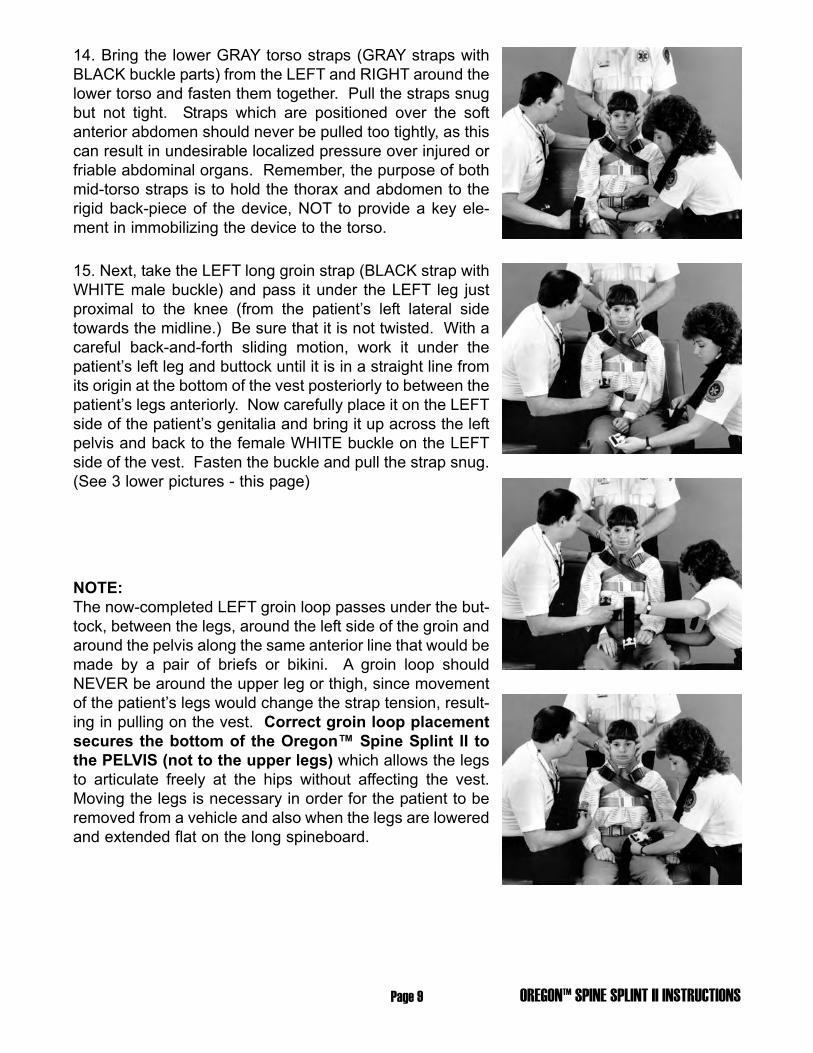
14. Bring the lower GRAY torso straps (GRAY straps withBLACK buckle parts) from the LEFT and RIGHT around thelower torso and fasten them together. Pull the straps snugbut not tight. Straps which are positioned over the softanterior abdomen should never be pulled too tightly, as thiscan result in undesirable localized pressure over injured orfriable abdominal organs. Remember, the purpose of bothmid-torso straps is to hold the thorax and abdomen to therigid back-piece of the device, NOT to provide a key ele-ment in immobilizing the device to the torso.
15. Next, take the LEFT long groin strap (BLACK strap withWHITE male buckle) and pass it under the LEFT leg justproximal to the knee (from the patient’s left lateral sidetowards the midline.) Be sure that it is not twisted. With acareful back-and-forth sliding motion, work it under thepatient’s left leg and buttock until it is in a straight line fromits origin at the bottom of the vest posteriorly to between thepatient’s legs anteriorly. Now carefully place it on the LEFTside of the patient’s genitalia and bring it up across the leftpelvis and back to the female WHITE buckle on the LEFTside of the vest. Fasten the buckle and pull the strap snug.(See 3 lower pictures - this page)
NOTE:The now-completed LEFT groin loop passes under the but-tock, between the legs, around the left side of the groin andaround the pelvis along the same anterior line that would bemade by a pair of briefs or bikini. A groin loop shouldNEVER be around the upper leg or thigh, since movementof the patient’s legs would change the strap tension, result-ing in pulling on the vest. Correct groin loop placementsecures the bottom of the Oregon™ Spine Splint II tothe PELVIS (not to the upper legs) which allows the legsto articulate freely at the hips without affecting the vest.Moving the legs is necessary in order for the patient to beremoved from a vehicle and also when the legs are loweredand extended flat on the long spineboard.

OREGON™ SPINE SPLINT II INSTRUCTIONS Page 10
16. Repeat this process with the RIGHT groin strap(BLACK strap with BLACK buckle parts). Thread it underthe right leg and move it back and forth until it is in a straightline from the back of the vest through the groin. Place it onthe RIGHT side of the genitalia and bring it up and acrossthe right pelvis (on the “brief” line), and fasten it to theRIGHT female groin buckle. Pull until snug. Check with thepatient that both LEFT and RIGHT groin loops are correct-ly positioned on the pelvis clear of the genitalia, and thenpull both groin loops tight.
17. Next, recheck all torso straps (shoulder, mid-torso, andgroin) and adjust them as necessary to assure that thedevice is firmly immobilized to the torso and cannot moveup-and-down or left-and-right.
ALTERNATE TO STEPS 11 and 12
When injury to the upper thorax (such as a fractured clavi-cle) makes it necessary to place straps so that they do notcross over the upper anterior thorax, the design of theupper straps (ORANGE and GREEN) allows for an alter-nate method. The ORANGE and GREEN straps on theLEFT side (and similarly the GREEN and ORANGE strapson the RIGHT side) have opposing male and female buck-les, This allows the EMT to pass the LEFT ORANGE strapover the LEFT shoulder and the LEFT (lower) GREEN strapunder the LEFT armpit. Now connect these straps (LEFTORANGE and LEFT GREEN) and tighten until snug. Thisforms a loop at the left upper thorax surrounding the leftarm. Now adjust both straps so that the buckle is posi-tioned on the anterior aspect and not on top of the shoulderor in the armpit. Once in place, pull it tight. Next, place theRIGHT (upper) GREEN strap over the RIGHT shoulder andbring the RIGHT (lower) ORANGE strap under the armpit.Connect and position the buckles correctly and tightenthem in place.
NOTE:This alternate method produces a loop from the vest over the shoulder, around the arm, andthrough the armpit on each side, without putting localized pressure on the clavicles in anundesirable place or crossing the upper thorax. These loops, if properly adjusted, willimmobilize the upper vest to the torso. Care must be taken to ensure that these loops areeach over the shoulders and on the torso and are not laterally placed or allowed to slidedown onto the upper arm.

Page 11 OREGON™ SPINE SPLINT II INSTRUCTIONS
Now that the OSS has been properly fastened to the torso,so that it cannot move up and down or left and right, it issafe to proceed to fastening the head.
NOTE:In most patients the scapula is more posteriorthan the back of the head. This results in a spaceranging from one-half to two inches between theback of their head and the head-piece of theOSS. This void behind the HEAD must be filledwith the correct amount of padding so that tightlyfastening the patient’s head to the device will notcause the head to move to hyperextension.Differing anatomy will cause the back of the headof a few patients, when maintained in a neutralin-line position, to rest directly on the head-pieceof the Oregon™ Spine Splint II - in which caseNO padding is necessary. In all cases, care mustbe taken not to insert too much padding, result-ing in moving the head to flexion.
PADDING BEHIND THE PATIENT’S HEAD, AS NEED-ED, IS KEY TO MAINTAINING PROPER NEUTRALALIGNMENT.
NO PADDING is necessary (or advised) BEHIND THENECK when a properly fitting rigid cervical collar (e.g., Stif-Neck, Philadelphia, etc.) is used, as the collar will supportthe neck. Padding behind the neck can inadvertently causelocalized posterior to anterior pressure at the cervical spine.
18. Carefully, without moving or jarring the hands of theEMT who is maintaining manual in-line immobilization, padbehind the head as needed to completely fill the spacebetween the patient’s head and the device. Use one ormore sections of the ORANGE padding provided with theOregon’” Spine Splint II, or use a small towel folded to thecorrect thickness. Fit the padding to the patient, NOT thepatient to the padding. Be sure the padding does notextend horizontally beyond the width of the two center slatsof the head portion of the OSS.

OREGON™ SPINE SPLINT II INSTRUCTIONS Page 12
NOTE:An alternative method of securing the patient’s head to thedevice is to use Kolban, Medi-Rip, or three inch adhesivetape. Wrap the tape first around the forehead three or fourtimes to include the anterior part of the supraorbital ridge,then around the cervical collar and neck portion of theOregon™ Spine Splint II.Check to assure that the patient’s vision and respiration arenot impaired and that the patient’s mouth can open/beopened with ease should vomiting later occur.
19. Without losing manual support and manual in-lineimmobilization (alternating if necessary between hands orbetween one EMT behind the patient and one in front), foldin the head flaps so that they are alongside the flat lateralplanes of the head. Maneuver each flap so that when final-ly in place, the EMT behind the patient is providing manualin-line support with his hands on the outside of the flaps.
20. Turn the Forehead Restraint Strap (black strap withopen cell foam Dispos-A-Pad) so that the non-slip pad istoward the patient’s forehead. Pull back any hair that cov-ers the forehead. Place the pad on the forehead so that thebottom edge covers the eyebrows and so that it is centeredleft-to-right. Pull both ends of the strap posteriorly, and fas-ten the strap to the Velcro surfaces of the lateral head flapson each side. Be sure that the Forehead Restraint Strap istight enough to grip the forehead and immobilize the upperhead.
21. Place the Collar Strap (black lower head strap, with twonarrow strips at its center section) on the rigid anterior por-tion of the cervical collar. Be sure that it is centered fromleft-to-right. Bring the ends of the strap posteriorly andslightly upwards, and fasten them to the Velcro surfaces ofthe lateral head flaps on each side. Ensure that the strapis snug enough to restrict any anterior movement of the cer-vical collar or neck, but not so tight as to push the cervicalcollar posteriorly or deform it.
WARNING: Use of anything that acts as a chin cup orseats the molars - holding the mouth closed - is CON-TRAINDICATED and, if vomiting occurs, can be fatal.

Page 13 OREGON™ SPINE SPLINT II INSTRUCTIONS
22. Check both head straps and adjust them as necessaryfor proper immobilization of the head. The EMT behind thepatient can now release the manual immobilization andmove his hands to support and steady the OSS II andpatient together by holding the upper loops or the uppertorso.
NOTE:ACCESS TO ANTERIOR CHEST AFTER OSS APPLIEDThe vest portion of the Oregon™ Spine Splint II and thepositioning of the straps has been designed so that mostof the anterior chest remains uncovered to allow for chestauscultation and the placement of EKG monitor leadsWITHOUT the need to adjust or remove any part of theimmobilization device.
23. Recheck ABC’s and Motor, Sensory, and Circulation inall four extremities (MSC x 4).
24. In the prescribed manner, place a long spineboard onthe seat just under the patient’s outside-facing buttock.Rotate and lower the patient onto the longboard. Holdingthe legs up slightly, slide the patient in controlled incre-ments towards the head of the spineboard until he is prop-erly positioned on it.
ALTERNATE TO STEP 24
In some situations, rotating the patient onto a prepositionedlong spineboard will not be possible. In such cases thepatient will have to be lifted onto the longboard, stokes lit-ter, rescue sled, or SKED. DO NOT lift the patient by theOSS II! With one EMT on each side, place your arms underthe patient’s legs and around his back and the OSS II, andlift both the patient and the splint together as one unit. Theloops at the back of the Oregon’” Spine Splint II are fur-nished solely to provide a positive grip for the hands at thepatient’s back when lifting correctly. These loops arestitched as an integral part of the “basket” formed by all ofthe webbing and stitching which encompass the patient andprovides the underlying strength of the Oregon’”SpineSplint II. The webbed straps, when properly applied to apatient, form an extremely strong unit whose strength sur-passes parameters of possible patient lifting weight.However, lifting solely by these loops may cause unwantedpressure on the patient. It can invite some movement ofthe device on the torso and result in an unstable center ofgravity. Such localized lifting should be avoided and should

NOTE: USING THE OSS WITH THE SKED® STRETCHER
The Oregon™ Spine Splint II comes with arigid Shoulder Board (approximately 20” x 5”).When the OSS II is to be used in rescue situ-ations in conjunction with a blanket lift, flexi-ble curved rescue sled, slatted fabric long-board, or SKED, this board should be added after the Oregon™ Spine Splint II is applied tothe patient and just prior to lowering the patient and OSS onto the blanket, flexible curved res-cue sled, slatted longboard, or SKED. The board fastens to the Velcro square at the back ofthe OSS, found just behind the shoulders. It should be centered and extend parallel to theshoulders, perpendicular to the midline of the patient’s back. It is designed so that the side-bending effect of the blanket, flexible curved rescue sled, slatted longboard, or SKED, will notrotate the patient’s shoulders anteriorly as can occur with any vest used in conjunction withthese specialized devices. When the Oregon™ Spine Splint II is used in conjunction with anormal long spineboard, scoop litter, or stokes litter this piece is NOT necessary.
only be considered in unusual rescue situations such ashoisting the patient through a narrow manhole or hatch.Even then a properly fitted tied or sewn full body harnessshould be applied around the patient and the Oregon™Spine Splint II to prevent movement of the device on thepatient as he is lifted from the hole. It should be recognizedas a dangerous maneuver and additional slinging as well asrescuer guidance and stabilization are necessary to properlyguide and protect the patient. Such rescue maneuversshould only be performed by personnel properly trained inthese procedures, which lie outside of normal EMT training.
25. Slowly and carefully lower the patient’s knees and legsuntil the patient is in a fully supine position on the longboard.In most patients, since the groin loops are over the pelvis, noadjustment is necessary prior to lowering the legs. In a fewcases where the patient is very muscular or obese, it may benecessary to loosen the tension on the groin loops slightly(but DO NOT REMOVE them!) prior to lowering the legs.
26. Provide necessary additional treatment. Tie the patient’sfeet together, immobilize both the patient and the Oregon™Spine Splint II to the long spineboard, and secure thepatient’s legs to the board. Add any additional straps,padding, etc., as needed to completely package the patientfor transport.
27. Recheck the patient’s Motor, Sensory, and Circulatorystatus in all four extremities, and continue to monitor thepatient’s ABC’s while enroute to the hospital.
OREGON™ SPINE SPLINT II INSTRUCTIONS Page 14

OREGON™ SPINE SPLINT II INSTRUCTIONSPage 15
NOTE: REPLACEMENT VELCRO BACKED FOAM DISPOS-A-PADS FOR THE FORE-HEAD RESTRAINT STRAP
Replacement pads are provided for the Forehead Restraint Strap. These pads should bereplaced after each use. Simply pull it off the Velcro on the head strap and replace it with a newpad, positioning it with the Velcro side against the centered area of Velcro on the foreheadstrap.
By: Alexander M. Butman, EMSI, REMT-PExecutive Director
General Editor: Richard W. Vomacka, REMT-PSenior Editor
Emergency Training InstituteAkron, Ohio 1989

PATENT NO.’S 4,665,908 & 5,027,833OTHER PATENTS PENDING
SPECIAL CONDITIONS
Where limited resources such as a military or off-road situation exists, since the OSS II has rigidslatting, and where no splint specifically designed as an arm or leg splint, or other suitable rigidsplinting material be available, the Oregon™ Spine Splint II can be temporarily used.
Use of the OSS II to immobilize the pelvis, hip or any other such use should not be attemptedunless it is specifically recommended by a Physician Medical Advisor.
Anti-shock trousers do not present any problems when used in conjunction with the OSS.
The complete anterior torso is open and accessible for any pre-hospital diagnosis or treatmentwithout compromising the immobilization.
REPACKING THE OREGON™ SPINE SPLINT
Always inspect the OSS for damaged parts or excessive wear prior torepacking it. If damage has occurred, replace or repair those parts beforeplacing the OSS back in service. The OSS can be cleaned with milddetergent or soapy water. Allow 24 to 36 hours drying time before storingit in its carrying case. Bleach solutions can also be used for prevention ofbloodborn pathogens.
Repacking Procedure - Pull the groin strap buckles down to within 1 inchof the end of the strap. Then pull these straps up inside of the OSS overthe top and secure them to the shoulderboard Velcro on the back. Foldthe OSS at the center and fasten the white tab to the shoulderboardVelcro. Turn the OSS over and spread out all of the chest and bodystraps. Neatly fold all straps against the OSS on the side (Torso) flaps.Do not stack any of the buckles on each other. Attach one end of the Collar and ForeheadRestraint Straps to each side of the head flap Velcro and lay the other ends the length of theOSS on top of the straps and buckles. Lift the side fabric flaps to form a pouch encasing all ofthe straps and buckles and attach three Velcro tabs to hold them in place. Fold the head flaps
against the OSS and place it in its carrying caseclosing the Velcro closure on the bag. Place theDispos-A-Pads along with the Shoulderboardand Head Pads in the zippered pouch. The OSSbag can then be inserted in a rolled-up Sked®
Stretcher within the Sked bag for storage.
SKEDCO, INC.P.O. Box 230487Portland, OR 97281Tel: 503-639-2119 Fax: 503-639-4538Order: 800-770-7533 Web: www.skedco.com
Free Comprehensive Video or VCD AvailableOSS II INST. 07/04