Embed Size (px)
Citation preview
IMMOBILIZER ANTI-THEFT SYSTEM 9T – 9
DAEWOO M–150 BL2
SECTION 9T
IMMOBILIZER ANTI-THEFT SYSTEM
CAUTION: Disconnect the negative battery cable before removing or installing any electrical unit or when atool or equipment could easily come in contact with exposed electrical terminals. Disconnecting this cablewill help prevent personal injury and damage to the vehicle. The ignition must also be in LOCK unlessotherwise noted.
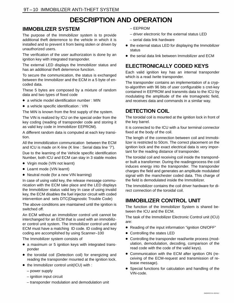
TABLE OF CONTENTSDescription and Operation 9T-10. . . . . . . . . . . . . . . . .
Immobilizer System 9T-10. . . . . . . . . . . . . . . . . . . . . . .
Electronically Coded Keys 9T-10. . . . . . . . . . . . . . . . .
Detection Coil 9T-10. . . . . . . . . . . . . . . . . . . . . . . . . . . .
Immobilizer Control Unit 9T-10. . . . . . . . . . . . . . . . . . .
Serial Data Link 9T-11. . . . . . . . . . . . . . . . . . . . . . . . . .
Electronic Control Module (ECM) 9T-11. . . . . . . . . . .
Security Indicator 9T-12. . . . . . . . . . . . . . . . . . . . . . . . .
Diagnostic Information and Procedures 9T-13. . . .
Immobilizer System (FENIX 5MR) 9T-13. . . . . . . . . .
Immobilizer System (SIRIUS D3) 9T-13. . . . . . . . . . .
DTC 1600 ECM Immobilizer Error (No Answer) 9T-14. . . . . . . . . . . . . . . . . . . . . . . . . . .
DTC 1601 ECM Immobilizer Error (Incorrect Answer) 9T-16. . . . . . . . . . . . . . . . . . . . . .
DTC 1602 ECM Immobilizer Error (ECM Locked) 9T-18. . . . . . . . . . . . . . . . . . . . . . . . .
P1628 ECM Immobilizer Error 9T-20. . . . . . . . . . . . . .
P1629 ECM Immobilizer Error 9T-22. . . . . . . . . . . . . .
Key Status Errors (FENIX 5MR) 9T-24. . . . . . . . . . . .
Key Status Errors (SIRIUS D3) 9T-24. . . . . . . . . . . . .
Communication Between Immobilizer and Test Equipment (FENIX 5MR) 9T-25. . . . . . . . . . . .
Communication Between Immobilizer and Test Equipment (SIRIUS D3) 9T-25. . . . . . . . . . . . .
Repair Instructions 9T-26. . . . . . . . . . . . . . . . . . . . . . . .
On-Vehicle Service 9T-26. . . . . . . . . . . . . . . . . . . . . . . . .
Key Coding Procedure 9T-26. . . . . . . . . . . . . . . . . . . .
ID Code Reprogramming 9T-26. . . . . . . . . . . . . . . . . .
Transponder 9T-27. . . . . . . . . . . . . . . . . . . . . . . . . . . . .
Detection Coil 9T-27. . . . . . . . . . . . . . . . . . . . . . . . . . . .
Immobilizer Control Unit 9T-28. . . . . . . . . . . . . . . . . . .
Specifications 9T-30. . . . . . . . . . . . . . . . . . . . . . . . . . . .
Fastener Tightening Specifications 9T-30. . . . . . . . . .
Schematic and Routing Diagrams 9T-31. . . . . . . . . .
Immobilizer Anti-Theft System 9T-31. . . . . . . . . . . . .
Remote Keyless Entry and Immobilizer Anti-theft System 9T-32. . . . . . . . . . . . . . . . . . . . . . .
9T – 10 IMMOBILIZER ANTI-THEFT SYSTEM
DAEWOO M–150 BL2
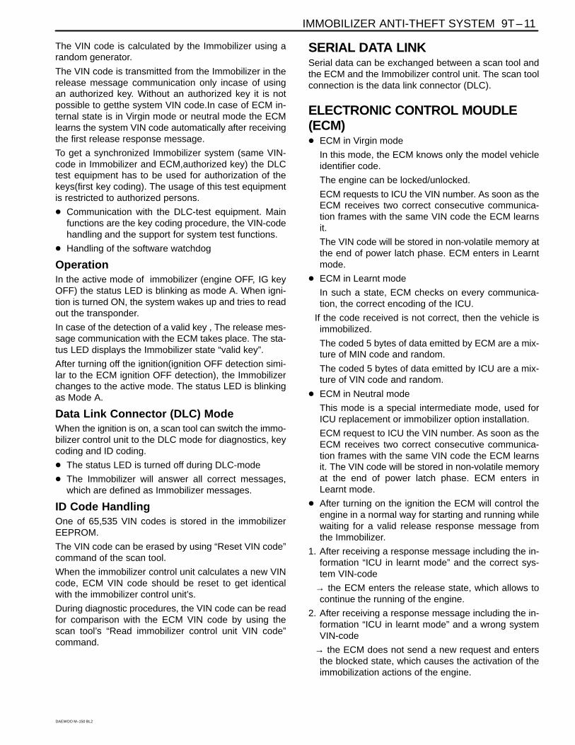
DESCRIPTION AND OPERATIONIMMOBILIZER SYSTEMThe purpose of the Immobilizer system is to provideadditional theft deterrence to the vehicle in which it isinstalled and to prevent it from being stolen or driven byunauthorized users.
The verification of the user authorization is done by anignition key with integrated transponder.
The external LED displays the Immobilizer status andhas an additional theft deterrence function.
To secure the communication, the status is exchangedbetween the Immobilizer and the ECM in a 5 byte of en-coded data.
These 5 bytes are composed by a mixture of randomdata and two types of fixed code
� a vehicle model identification number : MIN
� a vehicle specific identification : VIN
The MIN is known from the first supply of the system.
The VIN is realized by ICU on the special order from thekey coding (reading of transponder code and storing itas valid key code in Immobilizer EEPROM).
A different random data is computed at each key transi-tion.
All the immobilization communication between the ECMand ICU is made on K-line (K line : Serial data line ’7’).
Due to the learning of the Vehicle specific identificationNumber, both ICU and ECM can stay in 3 stable modes
� Virgin mode (VIN not learnt)
� Learnt mode (VIN learnt)
� Neutral mode (for a new VIN learning)
In case of using valid key, the release message commu-nication with the ECM take place and the LED displaysthe Immobilizer status valid key In case of using invalidkey, the ECM disables the fuel injector circuit with codedintervention and sets DTC(Diagnostic Trouble Code)
The above conditions are maintained until the ignition isswitched off.
An ECM without an immobilizer control unit cannot beinterchanged for an ECM that is used with an immobiliz-er control unit system. The Immobilizer control unit andECM must have a matching ID code. ID coding and keycoding are accomplished by using Scanner–100
The Immobilizer system consists of
� a maximum or 5 ignition keys with integrated trans-ponder
� the toroidal coil (Detection coil) for energizing andreading the transponder mounted at the ignition lock.
� the Immobilizer control unit(ICU) with :
– power supply
– ignition input circuit
– transponder modulation and demodulation unit
– EEPROM
– driver electronic for the external status LED
– serial data link hardware
� the external status LED for displaying the Immobilizerstatus
� the serial data link between Immobilizer and ECM
ELECTRONICALLY CODED KEYSEach valid ignition key has an internal transponderwhich is a read /write transponder.
The transponder contains an implementation of a cryp-to-algorithm with 96 bits of user configurable s cret-keycontained in EEPROM and transmits data to the ICU bymodulating the amplitude of the ele tromagnetic field,and receives data and commands in a similar way.
DETECTION COILThe toroidal coil is mounted at the ignition lock in front ofthe key barrel.
It is connected to the ICU with a four terminal connectorfixed at the body of the coil.
The length of the connection between coil and Immobi-lizer is restricted to 50cm. The correct placement on theignition lock and the exact electrical data is very impor-tant for the reading distance of transponder.
The toroidal coil and receiving coil inside the transpond-er built a transformer. During the readingprocess the coilinduces energy into the transponder. The transpondercharges the field and generates an amplitude modulatedsignal with the manchester coded data. This charge ofthe field is demodulated inside the Immobilizer.
The Immobilizer contains the coil driver hardware for di-rect connection of the toroidal coil.
IMMOBILIZER CONTROL UNITThe function of the Immobilizer System is shared be-tween the ICU and the ECM.
The task of the Immobilizer Electronic Control unit (ICU)are:
� Reading of the input information “ignition ON/OFF”
� Controlling the states LED
� Controlling the transponder read/write process (mod-ulation, demodulation, decoding, comparison of theread code with the code of the valid keys).
� Communication with the ECM after ignition ON (re-ceiving of the ECM-request and transmission of re-lease message).
� Special functions for calculation and handling of theVIN-code.
IMMOBILIZER ANTI-THEFT SYSTEM 9T – 11
DAEWOO M–150 BL2
The VIN code is calculated by the Immobilizer using arandom generator.
The VIN code is transmitted from the Immobilizer in therelease message communication only incase of usingan authorized key. Without an authorized key it is notpossible to getthe system VIN code.In case of ECM in-ternal state is in Virgin mode or neutral mode the ECMlearns the system VIN code automatically after receivingthe first release response message.
To get a synchronized Immobilizer system (same VIN-code in Immobilizer and ECM,authorized key) the DLCtest equipment has to be used for authorization of thekeys(first key coding). The usage of this test equipmentis restricted to authorized persons.
� Communication with the DLC-test equipment. Mainfunctions are the key coding procedure, the VIN-codehandling and the support for system test functions.
� Handling of the software watchdog
OperationIn the active mode of immobilizer (engine OFF, IG keyOFF) the status LED is blinking as mode A. When igni-tion is turned ON, the system wakes up and tries to readout the transponder.
In case of the detection of a valid key , The release mes-sage communication with the ECM takes place. The sta-tus LED displays the Immobilizer state “valid key”.
After turning off the ignition(ignition OFF detection simi-lar to the ECM ignition OFF detection), the Immobilizerchanges to the active mode. The status LED is blinkingas Mode A.
Data Link Connector (DLC) ModeWhen the ignition is on, a scan tool can switch the immo-bilizer control unit to the DLC mode for diagnostics, keycoding and ID coding.
� The status LED is turned off during DLC-mode
� The Immobilizer will answer all correct messages,which are defined as Immobilizer messages.
ID Code HandlingOne of 65,535 VIN codes is stored in the immobilizerEEPROM.
The VIN code can be erased by using “Reset VIN code”command of the scan tool.
When the immobilizer control unit calculates a new VINcode, ECM VIN code should be reset to get identicalwith the immobilizer control unit’s.
During diagnostic procedures, the VIN code can be readfor comparison with the ECM VIN code by using thescan tool’s “Read immobilizer control unit VIN code”command.
SERIAL DATA LINKSerial data can be exchanged between a scan tool andthe ECM and the Immobilizer control unit. The scan toolconnection is the data link connector (DLC).
ELECTRONIC CONTROL MOUDLE(ECM)� ECM in Virgin mode
In this mode, the ECM knows only the model vehicleidentifier code.
The engine can be locked/unlocked.
ECM requests to ICU the VIN number. As soon as theECM receives two correct consecutive communica-tion frames with the same VIN code the ECM learnsit.
The VIN code will be stored in non-volatile memory atthe end of power latch phase. ECM enters in Learntmode.
� ECM in Learnt mode
In such a state, ECM checks on every communica-tion, the correct encoding of the ICU.
If the code received is not correct, then the vehicle isimmobilized.
The coded 5 bytes of data emitted by ECM are a mix-ture of MIN code and random.
The coded 5 bytes of data emitted by ICU are a mix-ture of VIN code and random.
� ECM in Neutral mode
This mode is a special intermediate mode, used forICU replacement or immobilizer option installation.
ECM request to ICU the VIN number. As soon as theECM receives two correct consecutive communica-tion frames with the same VIN code the ECM learnsit. The VIN code will be stored in non-volatile memoryat the end of power latch phase. ECM enters inLearnt mode.
� After turning on the ignition the ECM will control theengine in a normal way for starting and running whilewaiting for a valid release response message fromthe Immobilizer.
1. After receiving a response message including the in-formation “ICU in learnt mode” and the correct sys-tem VIN-code
→ the ECM enters the release state, which allows tocontinue the running of the engine.
2. After receiving a response message including the in-formation “ICU in learnt mode” and a wrong systemVIN-code
→ the ECM does not send a new request and entersthe blocked state, which causes the activation of theimmobilization actions of the engine.
9T – 12 IMMOBILIZER ANTI-THEFT SYSTEM
DAEWOO M–150 BL2
3. If the ECM doesn’t receive a response message with-in a defined time from beginning of the release timeperiod or the ECM receives a no release answer
→ the ECM enters the blocked state, which causes theactivation of the immobilization actions of the engine.
� The inactive state of the Immobilizer (valid key/invalidkey) ends with turning off the ignition.
SECURITY INDICATORThere is a security indicator on the instrument panel.
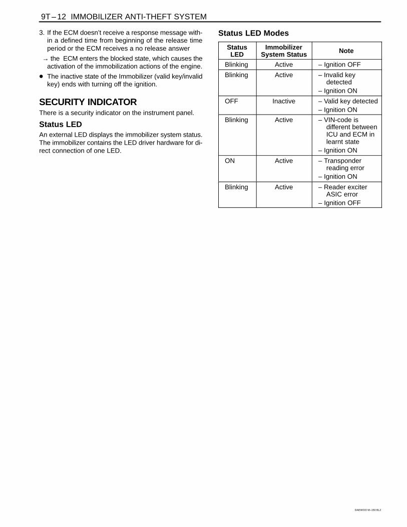
Status LEDAn external LED displays the immobilizer system status.The immobilizer contains the LED driver hardware for di-rect connection of one LED.
Status LED Modes
StatusLED
ImmobilizerSystem Status Note
Blinking Active – Ignition OFF
Blinking Active – Invalid keydetected
– Ignition ON
OFF Inactive – Valid key detected– Ignition ON
Blinking Active – VIN-code isdifferent betweenICU and ECM inlearnt state
– Ignition ON
ON Active – Transponderreading error
– Ignition ON
Blinking Active – Reader exciterASIC error
– Ignition OFF
IMMOBILIZER ANTI-THEFT SYSTEM 9T – 13
DAEWOO M–150 BL2
DIAGNOSTIC INFORMATION AND PROCEDURESIMMOBILIZER SYSTEM (FENIX 5MR)The immobilizer anti-theft system requires diagnosiswhen it is not possible to start the engine. If the no-startcondition occurs because of the immobilizer system, adiagnostic trouble code (DTC) 1600, 1601 or1602 should be set.
The immobilizer control unit monitors the detection andthe reading of the ignition key. The self-test capacity islimited to those functions. Faults are communicated to ascan tool during diagnosis, but they are not stored in theimmobilizer control unit’s memory.
Unauthorized use of a scan tool could be a method ofdefeating the immobilizer anti-theft system, so certainscan tool procedures require the use of a password. Thefollowing functions are password protected:
� Coding of an additional key.
� Deleting all key codes.
� Deletion of the immobilizer identification (ID) code.
� Deletion of the electronic control module (ECM) IDcode.
The following functions do not require a password:
� Reading an ignition key to determine if the transpond-er is working or if a key is authorized.
� Reading the immobilizer ID code to verify that itmatches the ECM ID code.
IMMOBILIZER SYSTEM (SIRIUS D3)The immobilizer anti-theft system requires diagnosiswhen it is not possible to start the engine. If the no-startcondition occurs because of the immobilizer system, adiagnostic trouble code (P) 1628, 1629 should be set.
The immobilizer control unit monitors the detection andthe reading of the ignition key. The self-test capacity islimited to those functions. Faults are communicated to ascan tool during diagnosis, but they are not stored in theimmobilizer control unit’s memory.
Unauthorized use of a scan tool could be a method ofdefeating the immobilizer anti-theft system, so certainscan tool procedures require the use of a password. Thefollowing functions are password protected:
� Coding of an additional key.
� Deleting all key codes.
The following functions do not require a password:
� Reading an ignition key to determine if the transpond-er is working or if a key is authorized.
� Reading the immobilizer ID code to verify that itmatches the ECM ID code.
9T – 14 IMMOBILIZER ANTI-THEFT SYSTEM
DAEWOO M–150 BL2
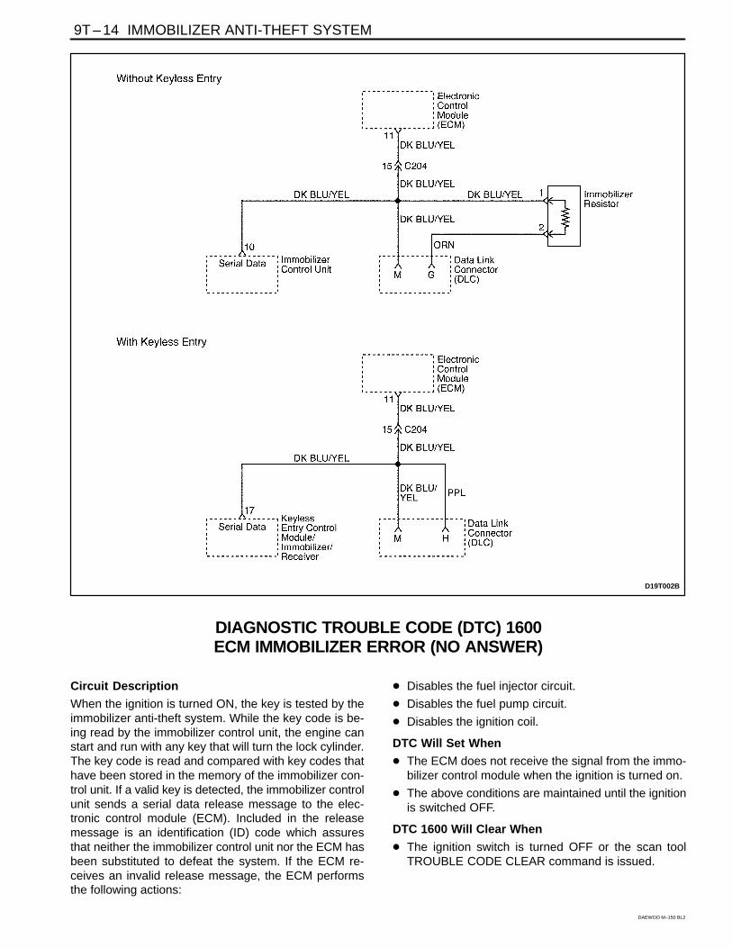
D19T002B
DIAGNOSTIC TROUBLE CODE (DTC) 1600ECM IMMOBILIZER ERROR (NO ANSWER)
Circuit Description
When the ignition is turned ON, the key is tested by theimmobilizer anti-theft system. While the key code is be-ing read by the immobilizer control unit, the engine canstart and run with any key that will turn the lock cylinder.The key code is read and compared with key codes thathave been stored in the memory of the immobilizer con-trol unit. If a valid key is detected, the immobilizer controlunit sends a serial data release message to the elec-tronic control module (ECM). Included in the releasemessage is an identification (ID) code which assuresthat neither the immobilizer control unit nor the ECM hasbeen substituted to defeat the system. If the ECM re-ceives an invalid release message, the ECM performsthe following actions:
� Disables the fuel injector circuit.
� Disables the fuel pump circuit.
� Disables the ignition coil.
DTC Will Set When
� The ECM does not receive the signal from the immo-bilizer control module when the ignition is turned on.
� The above conditions are maintained until the ignitionis switched OFF.
DTC 1600 Will Clear When
� The ignition switch is turned OFF or the scan toolTROUBLE CODE CLEAR command is issued.
IMMOBILIZER ANTI-THEFT SYSTEM 9T – 15
DAEWOO M–150 BL2
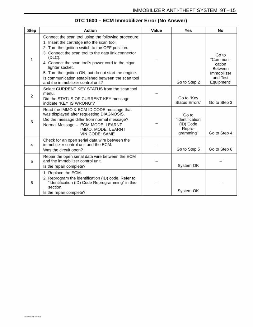
DTC 1600 – ECM Immobilizer Error (No Answer)
Step Action Value Yes No
1
Connect the scan tool using the following procedure:1. Insert the cartridge into the scan tool.2. Turn the ignition switch to the OFF position.3. Connect the scan tool to the data link connector
(DLC).4. Connect the scan tool’s power cord to the cigar
lighter socket.5. Turn the ignition ON, but do not start the engine.Is communication established between the scan tooland the immobilizer control unit?
–
Go to Step 2
Go to“Communi-
cationBetween
Immobilizerand Test
Equipment”
2
Select CURRENT KEY STATUS from the scan toolmenu.Did the STATUS OF CURRENT KEY messageindicate “KEY IS WRONG”?
–Go to “Key
Status Errors” Go to Step 3
3
Read the IMMO & ECM ID CODE message thatwas displayed after requesting DIAGNOSIS.Did the message differ from normal message?Normal Message – ECM MODE: LEARNT
IMMO. MODE: LEARNTVIN CODE: SAME
–
Go to“Identification
(ID) CodeRepro-
gramming” Go to Step 4
4Check for an open serial data wire between theimmobilizer control unit and the ECM.Was the circuit open?
–Go to Step 5 Go to Step 6
5Repair the open serial data wire between the ECMand the immobilizer control unit.Is the repair complete?
–System OK
–
6
1. Replace the ECM.2. Reprogram the identification (ID) code. Refer to
“Identification (ID) Code Reprogramming” in thissection.
Is the repair complete?
–
System OK
–
9T – 16 IMMOBILIZER ANTI-THEFT SYSTEM
DAEWOO M–150 BL2
D19T002B
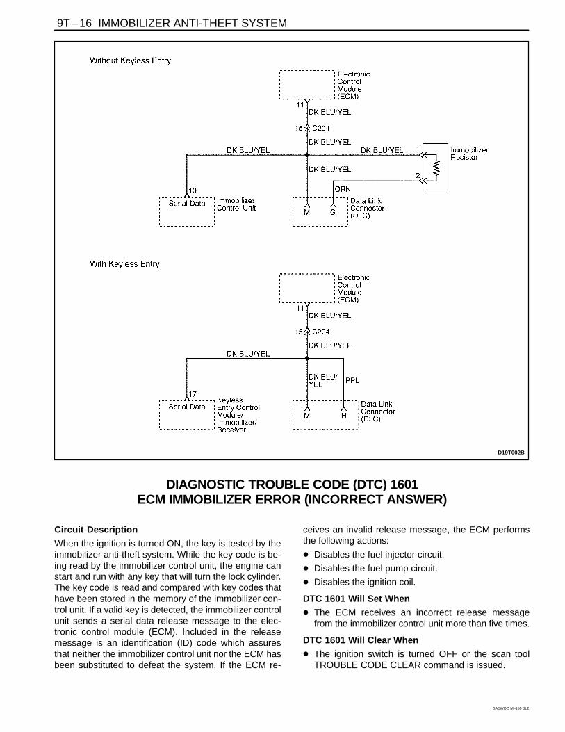
DIAGNOSTIC TROUBLE CODE (DTC) 1601ECM IMMOBILIZER ERROR (INCORRECT ANSWER)
Circuit Description
When the ignition is turned ON, the key is tested by theimmobilizer anti-theft system. While the key code is be-ing read by the immobilizer control unit, the engine canstart and run with any key that will turn the lock cylinder.The key code is read and compared with key codes thathave been stored in the memory of the immobilizer con-trol unit. If a valid key is detected, the immobilizer controlunit sends a serial data release message to the elec-tronic control module (ECM). Included in the releasemessage is an identification (ID) code which assuresthat neither the immobilizer control unit nor the ECM hasbeen substituted to defeat the system. If the ECM re-
ceives an invalid release message, the ECM performsthe following actions:
� Disables the fuel injector circuit.
� Disables the fuel pump circuit.
� Disables the ignition coil.
DTC 1601 Will Set When
� The ECM receives an incorrect release messagefrom the immobilizer control unit more than five times.
DTC 1601 Will Clear When
� The ignition switch is turned OFF or the scan toolTROUBLE CODE CLEAR command is issued.

IMMOBILIZER ANTI-THEFT SYSTEM 9T – 17
DAEWOO M–150 BL2
DTC 1601 – ECM Immobilizer Error (Incorrect Answer)
Step Action Value Yes No
1
Connect the scan tool using the following procedure:1. Insert the cartridge into the scan tool.2. Turn the ignition switch to the OFF.3. Connect the scan tool to the data link connector
(DLC).4. Connect the scan tool’s power cord to the cigar
lighter socket.5. Turn the ignition ON, but do not start the engine.Is communication established between the scan tooland the immobilizer control unit?
–
Go to Step 2
Go to“Communi-
cationBetween
Immobilizerand Test
Equipment”
2
1. Select CURRENT KEY STATUS from the scantool menu.
2. Read the STATUS OF CURRENT KEY message.Does the KEY STATUS message indicate “KEY ISWRONG”?
–Go to “Key
Status Errors” Go to Step 3
3
1. Select DIAGNOSIS from the scan tool menu.2. Read the IMMO & ECM ID CODE (immobilization
and electronic control module identification code)message.
Did the message differ from normal message?Normal Message – ECM MODE: LEARNT
IMMO. MODE: LEARNTVIN CODE: SAME
–Go to
“Identification(ID) Code
Repro-gramming” Go to Step 4
4
Check for an open serial data wire between theimmobilizer control unit and the electronic controlmodule (ECM).Was the circuit open?
–Go to Step 5 Go to Step 6
5Repair the open serial data wire between the ECMand the immobilizer control unit.Is the repair complete?
–System OK
–
61. Replace the ECM.2. Reprogram the ID code.Is the repair complete?
–System OK
–
9T – 18 IMMOBILIZER ANTI-THEFT SYSTEM
DAEWOO M–150 BL2
D19T002B
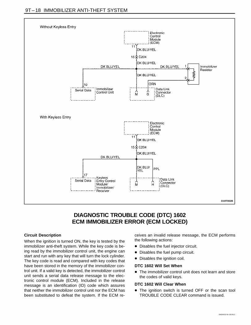
DIAGNOSTIC TROUBLE CODE (DTC) 1602ECM IMMOBILIZER ERROR (ECM LOCKED)
Circuit Description
When the ignition is turned ON, the key is tested by theimmobilizer anti-theft system. While the key code is be-ing read by the immobilizer control unit, the engine canstart and run with any key that will turn the lock cylinder.The key code is read and compared with key codes thathave been stored in the memory of the immobilizer con-trol unit. If a valid key is detected, the immobilizer controlunit sends a serial data release message to the elec-tronic control module (ECM). Included in the releasemessage is an identification (ID) code which assuresthat neither the immobilizer control unit nor the ECM hasbeen substituted to defeat the system. If the ECM re-
ceives an invalid release message, the ECM performsthe following actions:
� Disables the fuel injector circuit.
� Disables the fuel pump circuit.
� Disables the ignition coil.
DTC 1602 Will Set When
� The immobilizer control unit does not learn and storethe codes of valid keys.
DTC 1602 Will Clear When
� The ignition switch is turned OFF or the scan toolTROUBLE CODE CLEAR command is issued.
IMMOBILIZER ANTI-THEFT SYSTEM 9T – 19
DAEWOO M–150 BL2
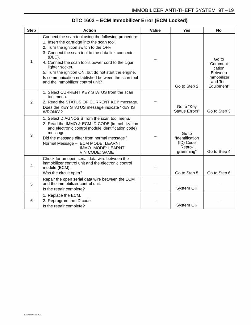
DTC 1602 – ECM Immobilizer Error (ECM Locked)
Step Action Value Yes No
1
Connect the scan tool using the following procedure:1. Insert the cartridge into the scan tool.2. Turn the ignition switch to the OFF.3. Connect the scan tool to the data link connector
(DLC).4. Connect the scan tool’s power cord to the cigar
lighter socket.5. Turn the ignition ON, but do not start the engine.Is communication established between the scan tooland the immobilizer control unit?
–
Go to Step 2
Go to“Communi-
cationBetween
Immobilizerand Test
Equipment”
2
1. Select CURRENT KEY STATUS from the scantool menu.
2. Read the STATUS OF CURRENT KEY message.Does the KEY STATUS message indicate “KEY ISWRONG”?
–Go to “Key
Status Errors” Go to Step 3
3
1. Select DIAGNOSIS from the scan tool menu.2. Read the IMMO & ECM ID CODE (immobilization
and electronic control module identification code)message.
Did the message differ from normal message?Normal Message – ECM MODE: LEARNT
IMMO. MODE: LEARNTVIN CODE: SAME
–Go to
“Identification(ID) Code
Repro-gramming” Go to Step 4
4
Check for an open serial data wire between theimmobilizer control unit and the electronic controlmodule (ECM).Was the circuit open?
–Go to Step 5 Go to Step 6
5Repair the open serial data wire between the ECMand the immobilizer control unit.Is the repair complete?
–System OK
–
61. Replace the ECM.2. Reprogram the ID code.Is the repair complete?
–System OK
–
9T – 20 IMMOBILIZER ANTI-THEFT SYSTEM
DAEWOO M–150 BL2
D209T002
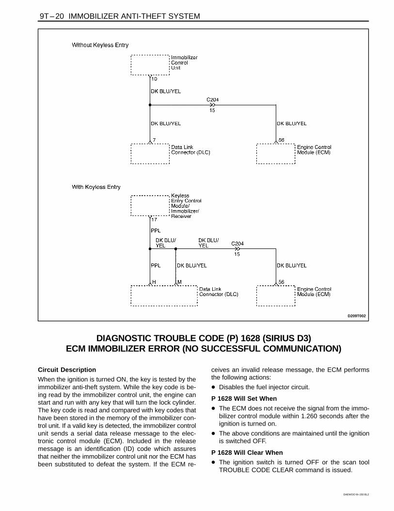
DIAGNOSTIC TROUBLE CODE (P) 1628 (SIRIUS D3)ECM IMMOBILIZER ERROR (NO SUCCESSFUL COMMUNICATION)
Circuit Description
When the ignition is turned ON, the key is tested by theimmobilizer anti-theft system. While the key code is be-ing read by the immobilizer control unit, the engine canstart and run with any key that will turn the lock cylinder.The key code is read and compared with key codes thathave been stored in the memory of the immobilizer con-trol unit. If a valid key is detected, the immobilizer controlunit sends a serial data release message to the elec-tronic control module (ECM). Included in the releasemessage is an identification (ID) code which assuresthat neither the immobilizer control unit nor the ECM hasbeen substituted to defeat the system. If the ECM re-
ceives an invalid release message, the ECM performsthe following actions:
� Disables the fuel injector circuit.
P 1628 Will Set When
� The ECM does not receive the signal from the immo-bilizer control module within 1.260 seconds after theignition is turned on.
� The above conditions are maintained until the ignitionis switched OFF.
P 1628 Will Clear When
� The ignition switch is turned OFF or the scan toolTROUBLE CODE CLEAR command is issued.
IMMOBILIZER ANTI-THEFT SYSTEM 9T – 21
DAEWOO M–150 BL2
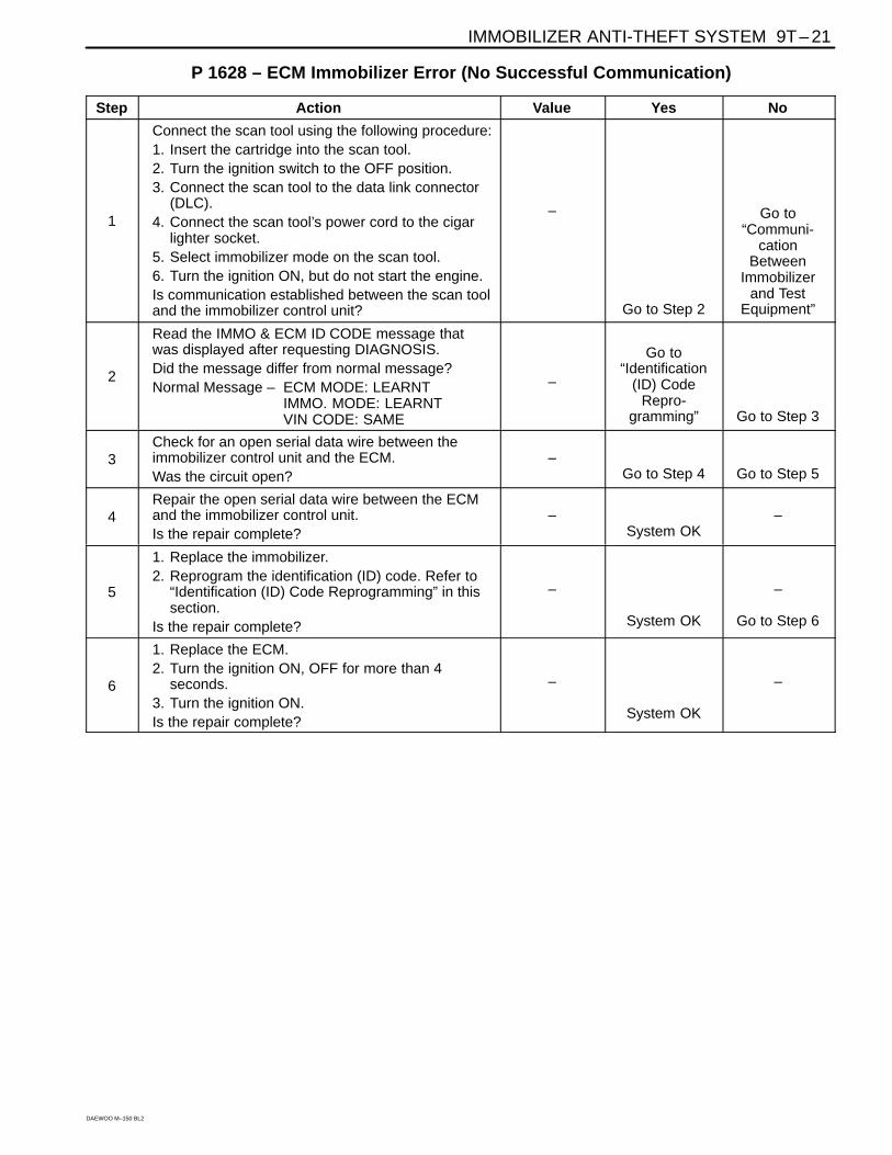
P 1628 – ECM Immobilizer Error (No Successful Communication)
Step Action Value Yes No
1
Connect the scan tool using the following procedure:1. Insert the cartridge into the scan tool.2. Turn the ignition switch to the OFF position.3. Connect the scan tool to the data link connector
(DLC).4. Connect the scan tool’s power cord to the cigar
lighter socket.5. Select immobilizer mode on the scan tool.6. Turn the ignition ON, but do not start the engine.Is communication established between the scan tooland the immobilizer control unit?
–
Go to Step 2
Go to“Communi-
cationBetween
Immobilizerand Test
Equipment”
2
Read the IMMO & ECM ID CODE message thatwas displayed after requesting DIAGNOSIS.Did the message differ from normal message?Normal Message – ECM MODE: LEARNT
IMMO. MODE: LEARNTVIN CODE: SAME
–
Go to“Identification
(ID) CodeRepro-
gramming” Go to Step 3
3Check for an open serial data wire between theimmobilizer control unit and the ECM.Was the circuit open?
–Go to Step 4 Go to Step 5
4Repair the open serial data wire between the ECMand the immobilizer control unit.Is the repair complete?
–System OK
–
5
1. Replace the immobilizer.2. Reprogram the identification (ID) code. Refer to
“Identification (ID) Code Reprogramming” in thissection.
Is the repair complete?
–
System OK
–
Go to Step 6
6
1. Replace the ECM.2. Turn the ignition ON, OFF for more than 4
seconds.3. Turn the ignition ON.Is the repair complete?
–
System OK
–
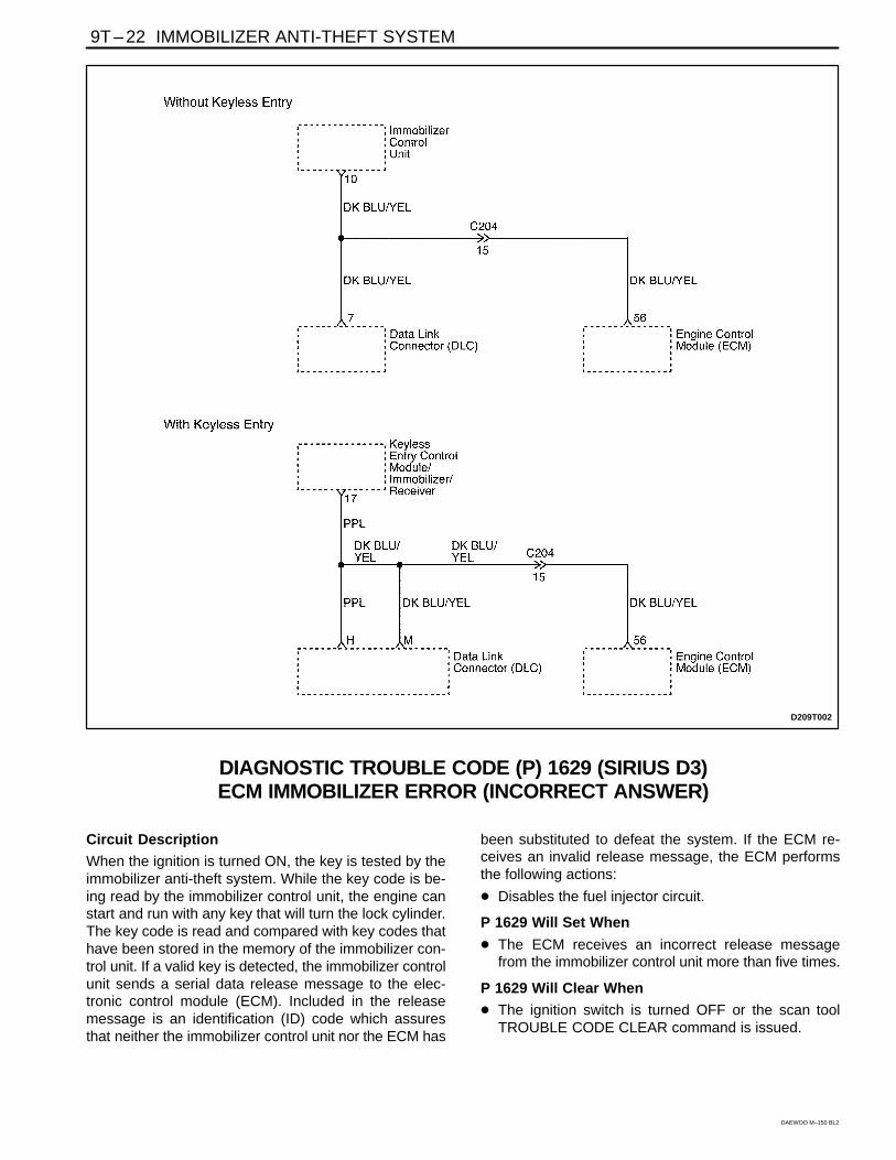
9T – 22 IMMOBILIZER ANTI-THEFT SYSTEM
DAEWOO M–150 BL2
D209T002
DIAGNOSTIC TROUBLE CODE (P) 1629 (SIRIUS D3)ECM IMMOBILIZER ERROR (INCORRECT ANSWER)
Circuit Description
When the ignition is turned ON, the key is tested by theimmobilizer anti-theft system. While the key code is be-ing read by the immobilizer control unit, the engine canstart and run with any key that will turn the lock cylinder.The key code is read and compared with key codes thathave been stored in the memory of the immobilizer con-trol unit. If a valid key is detected, the immobilizer controlunit sends a serial data release message to the elec-tronic control module (ECM). Included in the releasemessage is an identification (ID) code which assuresthat neither the immobilizer control unit nor the ECM has
been substituted to defeat the system. If the ECM re-ceives an invalid release message, the ECM performsthe following actions:
� Disables the fuel injector circuit.
P 1629 Will Set When
� The ECM receives an incorrect release messagefrom the immobilizer control unit more than five times.
P 1629 Will Clear When
� The ignition switch is turned OFF or the scan toolTROUBLE CODE CLEAR command is issued.
IMMOBILIZER ANTI-THEFT SYSTEM 9T – 23
DAEWOO M–150 BL2
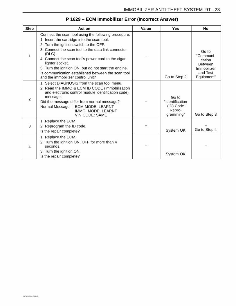
P 1629 – ECM Immobilizer Error (Incorrect Answer)
Step Action Value Yes No
1
Connect the scan tool using the following procedure:1. Insert the cartridge into the scan tool.2. Turn the ignition switch to the OFF.3. Connect the scan tool to the data link connector
(DLC).4. Connect the scan tool’s power cord to the cigar
lighter socket.5. Turn the ignition ON, but do not start the engine.Is communication established between the scan tooland the immobilizer control unit?
–
Go to Step 2
Go to“Communi-
cationBetween
Immobilizerand Test
Equipment”
2
1. Select DIAGNOSIS from the scan tool menu.2. Read the IMMO & ECM ID CODE (immobilization
and electronic control module identification code)message.
Did the message differ from normal message?Normal Message – ECM MODE: LEARNT
IMMO. MODE: LEARNTVIN CODE: SAME
–Go to
“Identification(ID) Code
Repro-gramming” Go to Step 3
31. Replace the ECM.2. Reprogram the ID code.Is the repair complete?
–System OK
–Go to Step 4
4
1. Replace the ECM.2. Turn the ignition ON, OFF for more than 4
seconds.3. Turn the ignition ON.Is the repair complete?
–
System OK
–
9T – 24 IMMOBILIZER ANTI-THEFT SYSTEM
DAEWOO M–150 BL2
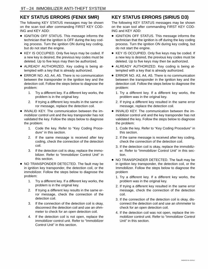
KEY STATUS ERRORS (FENIX 5MR)The following KEY STATUS messages may be shownon the scan tool after commanding FIRST KEY COD-ING and KEY ADD:
� IGNITION OFF STATUS. This message informs thetechnician that the ignition is OFF during the key cod-ing process. Turn the ignition ON during key coding,but do not start the engine.
� KEY IS OCCUPIED. Only five keys may be coded. Ifa new key is desired, the previous key codes must bedeleted. Up to five keys may then be authorized.
� ALREADY AUTHORIZED. Key coding is being at-tempted with a key that is already authorized.
� ERROR NO. A3, A4, A5. There is no communicationbetween the transponder in the ignition key and thedetection coil. Follow the steps below to diagnose theproblem:
1. Try a different key. If a different key works, theproblem is in the original key.
2. If trying a different key results in the same er-ror message, replace the detection coil.
� INVALID KEY. The communication between the im-mobilizer control unit and the key transponder has notvalidated the key. Follow the steps below to diagnosethe problem:
1. Code the key. Refer to “Key Coding Proce-dure” in this section.
2. If the same message is received after keycoding, check the connection of the detectioncoil.
3. If the detection coil is okay, replace the immo-bilizer. Refer to “Immobilizer Control Unit” inthis section.
� NO TRANSPONDER DETECTED. The fault may bein ignition key transponder, the detection coil, or theimmobilizer. Follow the steps below to diagnose theproblem:
1. Try a different key. If a different key works, theproblem is in the original key.
2. If trying a different key results in the same er-ror message, check the connection of thedetection coil.
3. If the connection of the detection coil is okay,disconnect the detection coil and use an ohm-meter to check for an open detection coil.
4. If the detection coil is not open, replace theimmobilizer control unit. Refer to “ImmobilizerControl Unit” in this section.
KEY STATUS ERRORS (SIRIUS D3)The following KEY STATUS messages may be shownon the scan tool after commanding FIRST KEY COD-ING and KEY ADD:
� IGNITION OFF STATUS. This message informs thetechnician that the ignition is off during the key codingprocess. Turn the ignition ON during key coding, butdo not start the engine.
� KEY IS OCCUPIED. Only five keys may be coded. Ifa new key is desired, the previous key codes must bedeleted. Up to five keys may then be authorized.
� ALREADY AUTHORIZED. Key coding is being at-tempted with a key that is already authorized.
� ERROR NO. A3, A4, A5. There is no communicationbetween the transponder in the ignition key and thedetection coil. Follow the steps below to diagnose theproblem:
1. Try a different key. If a different key works, theproblem was in the original key.
2. If trying a different key resulted in the same errormessage, replace the detection coil.
� INVALID KEY. The communication between the im-mobilizer control unit and the key transponder has notvalidated the key. Follow the steps below to diagnosethe problem:
1. Code the key. Refer to “Key Coding Procedure” inthis section.
2. If the same message is received after key coding,check the connection of the detection coil.
3. If the detection coil is okay, replace the immobiliz-er. Refer to “Immobilizer Control Unit” in this sec-tion.
� NO TRANSPONDER DETECTED. The fault may bein ignition key transponder, the detection coil, or theImmobilizer. Follow the steps below to diagnose theproblem
1. Try a different key. If a different key works, theproblem was in the original key.
2. If trying a different key resulted in the same errormessage, check the connection of the detectioncoil.
3. If the connection of the detection coil is okay, dis-connect the detection coil and use an ohmmeter tocheck for an open detection coil.
4. If the detection coil was not open, replace the im-mobilizer control unit. Refer to “Immobilizer ControlUnit” in this section.
IMMOBILIZER ANTI-THEFT SYSTEM 9T – 25
DAEWOO M–150 BL2
COMMUNICATION BETWEENIMMOBILIZER CONTROL UNIT ANDTEST EQUIPMENT (FENIX 5MR)1. Connect the test equipment as described in the Scan
Tool Equipment Manual.
2. If communication between the scan tool and the testequipment was unsuccessful, wait 30 seconds andtry again.
3. If communication was not successful on the secondtry, turn the ignition OFF and check the wire and con-nectors between the immobilizer control unit termi-nal 10 (17) and the data link connector (DLC) terminalM.
4. If the wire and connectors between the DLC and theimmobilizer control unit are okay, replace the immobi-lizer control unit. Refer to “Immobilizer Control Unit” inthis section.
Notice: Install the resistor cover in the DLC connec-tor after remove the scan tool. Because ECM Immo-bilizer Error Problem may exist.
COMMUNICATION BETWEENIMMOBILIZER CONTROL UNIT ANDTEST EQUIPMENT (SIRIUS D3)1. Connect the test equipment as described in the Scan
Tool Equipment Manual.
2. If communication between the scan tool and the testequipment was unsuccessful, wait 30 seconds andtry again.
3. If communication was not successful on the secondtry, turn the ignition OFF and check the wire and con-nectors between the immobilizer control unit termi-nal 10 and the data link connector (DLC) terminal 7(8).
4. If the wire and connectors between the DLC and theimmobilizer control unit are okay, replace the immobi-lizer control unit. Refer to “Immobilizer Control Unit” inthis section.
9T – 26 IMMOBILIZER ANTI-THEFT SYSTEM
DAEWOO M–150 BL2
REPAIR INSTRUCTIONS
ON-VEHICLE SERVICE
KEY CODING PROCEDURE1. Install the immobilizer control unit cartridge in the
scan tool.
2. Turn the ignition OFF
3. Connect the scan tool.
4. Turn the ignition ON with the key to be coded.
5. Enter the four-digit password that enables servicepersonnel to use the scan tool for coding keys.
6. A lost key can be deleted only by deleting all keysand reauthorizing the remaining keys as new keys.If a key is lost, go to the next step. If no keys havebeen lost but an additional key is desired, go to Step8.
7. Use the scan tool command DELETE ALL KEYCODES.
8. Use the scan tool command AUTHORIZE ONEADDITIONAL KEY.
9. Repeat Steps 4, 5, and 6 until the immobilizer con-trol unit has recorded all of the new keys or, after adeletion, has reauthorized all of the remaining keys.The immobilizer control unit can record a maximumof five keys.
10. Return the system to the normal mode.
11. Turn OFF the ignition.
12. Turn ON the ignition.
13. Crank to start the engine.
ID CODE REPROGRAMMINGReprogram the identification (ID) code in the followingsituations:
� An immobilizer control unit has been replaced.
� An electronic control module (ECM) has been re-placed.
If a valid key has been lost, refer to “Key Coding Proce-dure” in this section.
Reprogramming Procedure1. Turn the ignition OFF. Reprogramming is not allowed
while the engine is running.
2. Insert the immobilizer control unit cartridge into thescan tool.
3. Do not start the vehicle, but turn the ignition ON.
4. Enter the four-digit password that enables servicepersonnel to use the scan tool for ID code reprogram-ming.
5. Use the scan tool to command RESET ID CODE.
IMMOBILIZER ANTI-THEFT SYSTEM 9T – 27
DAEWOO M–150 BL2
6. Turn the ignition OFF and ON again, but do notcrank or start the engine. The ECM will reset theECM ID code to match the new ID code that wascalculated and sent by the immobilizer control unitwhen the ignition was first turned ON after the resetcommand.
7. Return the system to the normal mode.
8. Turn OFF the ignition.
9. Turn ON the ignition.
10. Start the engine.
After reprogramming the ID code, the scan tool SYS-TEM DIAGNOSIS command can verify that the ECM IDcode matches the immobilizer control unit ID code.
If the reprogramming procedure does not result inmatching ID codes, check the electrical connectors forthe serial data wire between the immobilizer control unitand the ECM.
TRANSPONDEREach valid ignition key has an internal transponderwhich is a read /write transponder.
The transponder contains an implementation of a cryp-to-algorithm with 96 bits of user configurable secret-keycontained in EEPROM and transmits data to the ICU bymodulating the amplitude of the electromagnetic field,and receives data and commands in a similar way.
D105A504
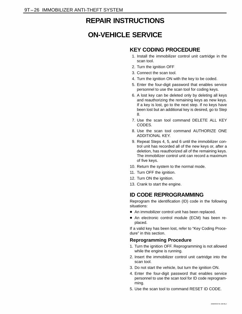
DETECTION COIL(Left–Hand Drive Shown, Right–HandDrive Similar)
Removal Procedure1. Remove the steering column covers. Refer to Section
6E, Steering Wheel and Column.
D29T001
2. Remove the detection coil.
� Disconnect the two-pin connector from the detec-tion coil (1).
� Pry the detection coil away from the lock cylinder(2).
Important: If the detection coil will be replaced with anew one, it does not matter if the key position trim ring isdamaged during removal. A new trim ring is part of thenew detection coil.
9T – 28 IMMOBILIZER ANTI-THEFT SYSTEM
DAEWOO M–150 BL2
D29T002
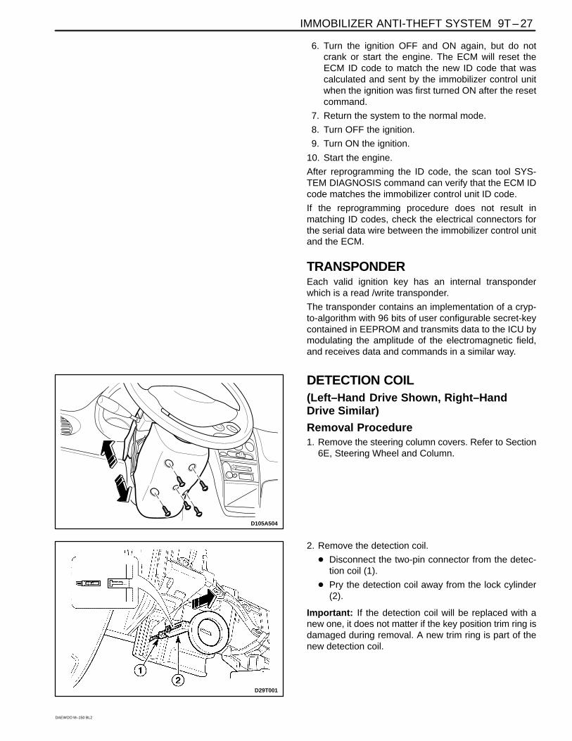
Installation Procedure1. Install the detection coil by pressing it onto the lock
cylinder until it snaps in place.
2. Connect the two-pin connector to the immobilizer.
D105A505
3. Install the steering column covers with the screws.Refer to Section 6E, Steering Wheel and Column.
D105A504
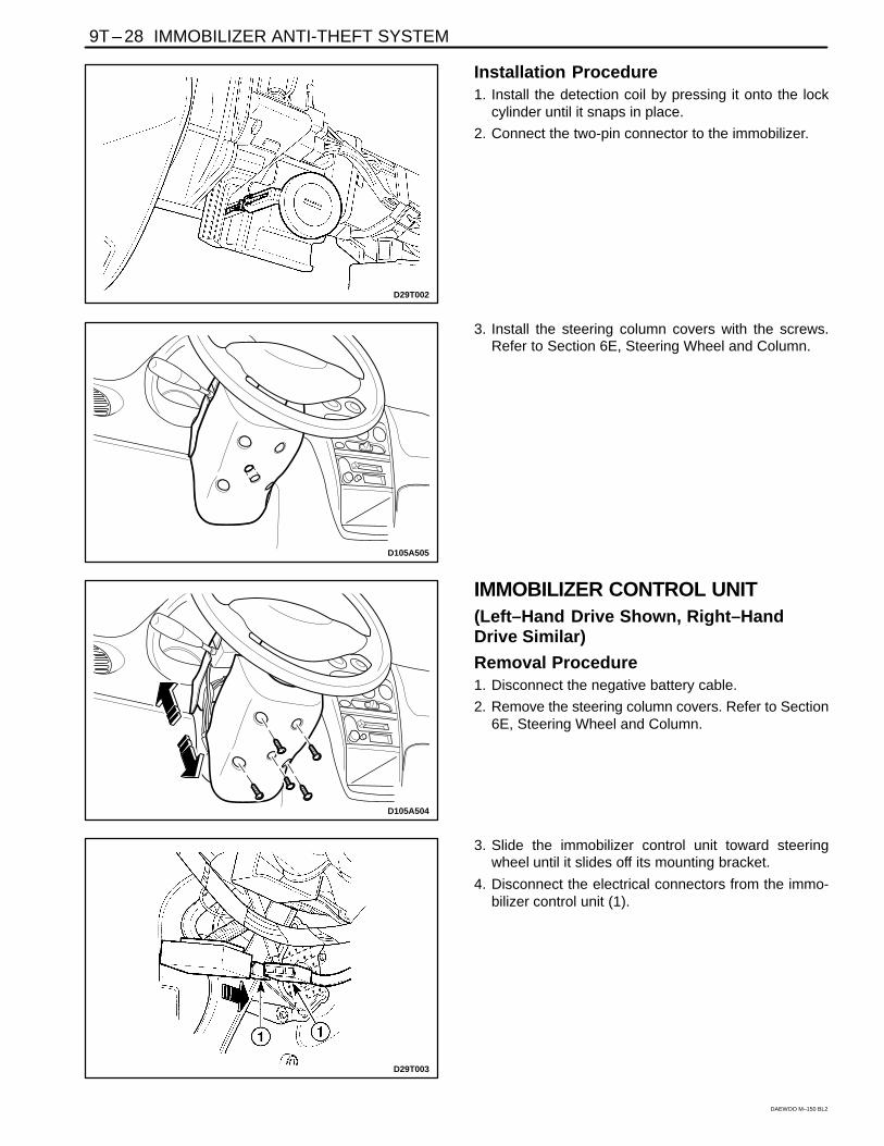
IMMOBILIZER CONTROL UNIT(Left–Hand Drive Shown, Right–HandDrive Similar)
Removal Procedure1. Disconnect the negative battery cable.
2. Remove the steering column covers. Refer to Section6E, Steering Wheel and Column.
D29T003
3. Slide the immobilizer control unit toward steeringwheel until it slides off its mounting bracket.
4. Disconnect the electrical connectors from the immo-bilizer control unit (1).
IMMOBILIZER ANTI-THEFT SYSTEM 9T – 29
DAEWOO M–150 BL2
D29T004
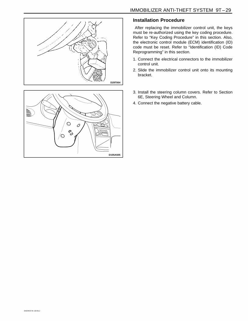
Installation Procedure
After replacing the immobilizer control unit, the keysmust be re-authorized using the key coding procedure.Refer to “Key Coding Procedure” in this section. Also,the electronic control module (ECM) identification (ID)code must be reset. Refer to “Identification (ID) CodeReprogramming” in this section.
1. Connect the electrical connectors to the immobilizercontrol unit.
2. Slide the immobilizer control unit onto its mountingbracket.
D105A505
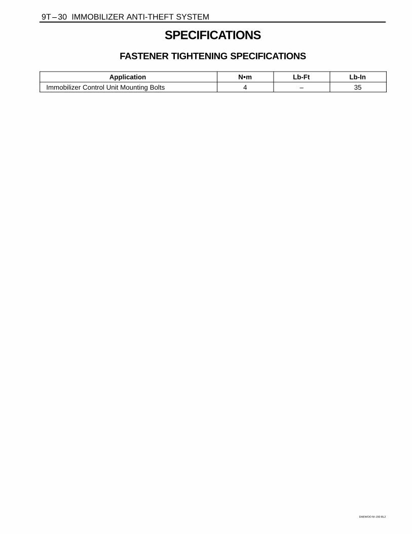
3. Install the steering column covers. Refer to Section6E, Steering Wheel and Column.
4. Connect the negative battery cable.
9T – 30 IMMOBILIZER ANTI-THEFT SYSTEM
DAEWOO M–150 BL2
SPECIFICATIONS
FASTENER TIGHTENING SPECIFICATIONSÑÑÑÑÑÑÑÑÑÑÑÑÑÑÑÑÑÑÑÑÑÑÑÑÑÑÑÑÑÑÑÑÑÑÑÑApplication
ÑÑÑÑÑÑÑÑÑÑÑÑÑÑN�m
ÑÑÑÑÑÑÑÑÑÑÑÑLb-Ft
ÑÑÑÑÑÑÑÑÑÑÑÑÑÑLb-In
Immobilizer Control Unit Mounting Bolts 4 – 35
IMMOBILIZER ANTI-THEFT SYSTEM 9T – 31
DAEWOO M–150 BL2
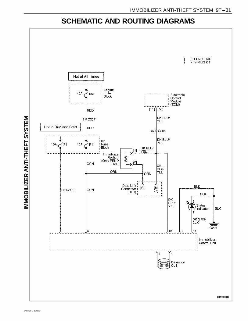
SCHEMATIC AND ROUTING DIAGRAMS
D19T001B
IMM
OB
ILIZ
ER
AN
TI-T
HE
FT S
YS
TEM
9T – 32 IMMOBILIZER ANTI-THEFT SYSTEM
DAEWOO M–150 BL2
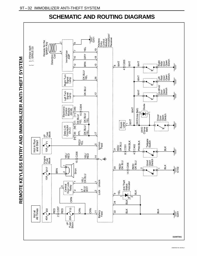
SCHEMATIC AND ROUTING DIAGRAMS
D209T001
RE
MO
TE
KE
YL
ES
S E
NT
RY
AN
D IM
MO
BIL
IZE
R A
NT
I-T
HE
FT
SY
ST
EM