Embed Size (px)
Citation preview
WATER-SOURCE HEAT PUMP SYSTEMS
T H E S M A R T S O L U T I O N F O R E N E R G Y E F F I C I E N C Y
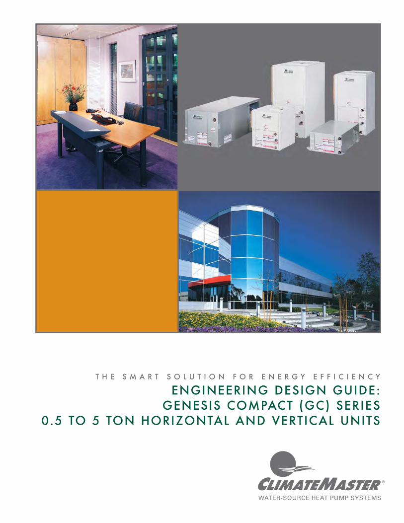
ENGINEERING DESIGN GUIDE:GENESIS COMPACT (GC) SERIES
0.5 TO 5 TON HORIZONTAL AND VERTICAL UNITS


T h e S m a r t C h o i c e f o r E n e r g y E f f i c i e n c y
1
T hh e S m a r t C h o i c e f o r E n e r g
TABLE OF CONTENTS
Commercial HVAC ..................................................................................................................................................................2
System Comparisons ..............................................................................................................................................................3
Water-Source Heat Pumps .....................................................................................................................................................4
An Application Example ........................................................................................................................................................5
The ClimateMaster Advantage .............................................................................................................................................6
GC Unit Features and Performance ......................................................................................................................................10
About ARI/ISO ........................................................................................................................................................................12
ARI/ISO Data ...........................................................................................................................................................................13
Model Nomenclature, Reference Calculations, Legend, & Correction Tables .................................................................14
Selection Example ..................................................................................................................................................................16
Performance Data ...................................................................................................................................................................17
Physical Data ...........................................................................................................................................................................28
Physical Dimensions (Horizontal Units) .................................................................................................................................29
Physical Dimensions (Vertical Units) ......................................................................................................................................35
Blower Performance Data - Standard Units Without Reheat ..............................................................................................42
ClimaDry Reheat Performance ..............................................................................................................................................44
Electrical Data .........................................................................................................................................................................45
Wiring Diagram Matrix ...........................................................................................................................................................47
Typical Wiring Diagram - CXM ..............................................................................................................................................48
Typical Wiring Diagram - DXM ..............................................................................................................................................49
CXM/DXM Control Features..................................................................................................................................................50
CXM/DXM Feature Comparison ...........................................................................................................................................52
GC WSHP Specifi cations ........................................................................................................................................................53
Guide Revision Log ................................................................................................................................................................60
Revised: 07/24/06D

2
C l i m a t e M a s t e r W a t e r - S o u r c e H e a t P u m p sG e n e s i s C o m p a c t ( G C ) S e r i e s
0 . 5 t o 5 T o n H o r i z o n t a l a n d V e r t i c a l U n i t s
COMMERCIAL HVAC
The ever-changing environment of commercial construction offers exciting breakthroughs in technology and materials, but it is not without some heartburn. Today, owners, architects, and contractors face many challenges in the design and construction of their projects. Challenges such as usable space, indoor air quality, energy effi ciency, maintenance costs, building longevity, and the LEED® program all come to the forefront of the design process. When considering the solutions to these challenges, the type of HVAC system chosen directly affects each one.
USABLE SPACEIt has been said that the reason real estate grows in value is because no one is making any more. As cities continue to grow and spread out, the value of maximizing usable space becomes increasingly important. When selecting an HVAC system, you positively or negatively impact the usable space on a project. As an example, VAV (Variable Air Volume) systems utilize complicated ductwork systems along with extensive equipment rooms to deliver conditioned air into the building space. Additionally, VAV duct systems many times require more ceiling height which increases fl oor-to-fl oor space thus increasing building costs. By comparison, ClimateMaster Water-Source and Geothermal Heat Pump systems require little to no equipment room space and use a very simple, compact, and independent ductwork system.
INDOOR AIR QUALITYAs important as the actual temperature of a building space is, the quality of air within that space is equally important. The American Society of Heating, Refrigerating, and Air Conditioning Engineers (ASHRAE) has implemented Standard 62, which requires signifi cantly higher amounts of fresh outdoor air for buildings. The challenge now becomes how to properly introduce, condition, and deliver this fresh air into the building space. Traditional options like two- and four-pipe Fan Coil systems must be up-sized signifi cantly to handle the additional conditioning load. This means larger, more expensive units, larger, more expensive piping, and larger more expensive boilers and chillers. In comparison, ClimateMaster systems offer a variety of options that can actually lower the overall system size, introduce 100% outdoor air, and lower system usage cost.
ENERGY EFFICIENCYToday’s offi ces equipped with computers, copiers and other offi ce tools can dramatically affect the heating and cooling load of a given space. When considering heating and cooling loads, rising energy costs demand an HVAC system that is effi cient while building designs require a system that is also fl exible. ClimateMaster has a solution for practically any application, and does so with some of most energy effi cient HVAC systems available on the market today. In fact, all of ClimateMaster’s products either meet or exceed the new federal mandated effi ciency minimums.
MAINTENANCE COSTSComplex systems such as two- and four-pipe fan coils and VAV systems require advanced maintenance and the trained personnel to perform it. Large equipment rooms fi lled with chillers, air handlers, or large-scale boilers require personnel for monitoring and maintenance, which consume building space and leasing profi ts. The effect to the bottom line becomes signifi cant when considering the potential of a complete system failure along with costly parts and equipment replacement. However, Water-Source and Geothermal Heat Pumps require very little monitoring and maintenance - aside from routine fi lter changes. With factory installed DDC controls, the entire building can be accessed via any web-enabled computer for monitoring and set point control. No muss, no fuss, no worries.
BUILDING LONGEVITY New innovations offer longer life expectancies for today’s buildings. You should expect the same from the HVAC systems being placed inside these buildings. However, when it comes to longevity, not all systems are created equal. Complex chillers and air handling systems often have a large number of moving parts that will wear out over time. Water-Source and Geothermal Heat Pumps offer the advantage of very few moving parts. Fewer moving parts lower the occurrence of parts replacement and extend equipment life. This simplicity of design allows ClimateMaster systems to provide average life spans of 20 years or more. In fact, there are a number of ClimateMaster units that are still performing after 50 years - providing the continual comfort our customers have come to expect.

T h e S m a r t C h o i c e f o r E n e r g y E f f i c i e n c y
3
T hh e S m a r t C h o i c e f o r E n e r g
MANY CHOICES, ONE SOLUTION
When choosing a HVAC system for a project, there are four basic types from which to choose.
FAN COILSFan coil systems are comprised of water-to-air coil air handlers connected via a two- or four-pipe insulated water loop. Fan coils require complex chillers and boilers to provide water loop fl uid in a particular temperature range (i.e. chilled water for cooling and hot water for heating). Two-pipe fan coils have a major disadvantage as control is substantially limited to whatever mode the system is currently set at (i.e. cooling or heating). A four-pipe version can be installed that requires both chilled and heated water to be available at the same time. Four-pipe systems also require twice the piping and twice the circulation equipment of a two-pipe system, which makes a four-pipe system one of the most expensive systems to install.
VARIABLE AIR VOLUME (VAV)Variable Air Volume, or VAV, is one of the most common types of HVAC systems used in large commercial buildings today. A typical system is usually comprised of a large air handler, central ductwork system, and a relatively large equipment room. Conditioned air is distributed throughout the building via a central ductwork system and is regulated via dampers in each space. VAV systems typically have a higher fi rst cost than Water-Source Heat Pumps, and may have similar operating costs, resulting in overall increased life cycle costs.
ROOFTOPRooftop systems are similar to VAV systems in that they use a central ductwork system to distribute conditioned air into the building space. However, instead of one central unit, the system is comprised of multiple units which can be tasked for different conditioning requirements. Rooftop systems usually require additional structural reenforcement as well as cranes or other lifting equipment to place the units. Control in a particular zone is limited to what the system is currently set to (i.e. cooling or heating). Rooftop installation costs are low to moderate, but operating costs are typically 50% higher than Water-Source Heat Pumps. Additionally, the systems are exposed to the elements and are subject to damage and vandalism.
WATER-SOURCE AND GEOTHERMAL HEAT PUMPSWater-Source and Geothermal Heat Pump systems are comprised of individual packaged units that transfer heat via a single- or two-pipe water loop. Each unit can be used in either heating or cooling mode year-round and loop temperature is maintained via a boiler/tower combination or earth-coupled loop. Each zone has complete control of its heating/cooling mode and each unit is independent from the others. This means if one unit goes down, the whole system is not affected. Controls can be as simple as one unit, one thermostat. Water-Source and Geothermal Heat Pump systems are the most energy, cost, and space effi cient of any system in the industry.
SYSTEM COMPARISON
System
Ease o
f Desig
n
Ease o
f Installation
Installation Sp
ace
Installation C
ost
Maintenance R
equirem
ents
Maintenance C
osts
Future System E
xpansio
n
Sound
Levels
Op
erating C
osts
Total Zo
ne Failure Chance
Individ
ual Tenant Co
ntrol
Op
tions
Ad
ditio
nal Auxiliary
Eq
uipm
ent Need
ed
Structure M
od
ifi cation N
eeds
System Lo
ngevity
Two-Pipe Fan Coils Low Low High Med High High Low Low Med High Low Low High High Med
Four-Pipe Fan Coils Low Low High High High High Low Low High High Low Low High High Med
PTAC / PTHP Low Low Low Low High High Med High High Low Med Low Med High Low
VAV Low Low High Med High High Low Med Med High Low Low High High Med
Rooftop Low Low High Low Med High Low Med Med High Low Low Med High Med
Water-source Heat Pumps High High Low Low Low Low High Low Low Low High High Low Low High
Geothermal Heat Pumps High High Low Low Low Low High Low Low Low High High Low Low High

4
C l i m a t e M a s t e r W a t e r - S o u r c e H e a t P u m p sG e n e s i s C o m p a c t ( G C ) S e r i e s
0 . 5 t o 5 T o n H o r i z o n t a l a n d V e r t i c a l U n i t s
WATER-SOURCE HEAT PUMPS
As the most energy effi cient HVAC systems on the market, Water-Source Heat Pumps are uniquely simple in design. Heat is moved through an interconnected water loop and either rejected through a cooling tower, or put to work in other areas. Each unit is an independent, packaged system, eliminating the chance of a total system failure. If one unit goes down, the other units are not affected. Conveniently located above the ceiling or in a closet, units can be easily accessed.
SYSTEM MODESWater-Source Heat Pump systems can operate in one of four modes depending on the space conditioning requirements. The versatility of operation allows Water-Source Heat Pumps to show their full potential as a solution for customized comfort and fl exibility.
COOLING MODE
The system extracts heat from the air and rejects it into the water loop through the coaxial refrigerant-to-water heat exchanger. This heat can either be moved to a different part of the building to satisfy a heating mode requirement, or be rejected out of the building via a cooling tower.
HEATING MODEThe system extracts heat from the water loop through the coaxial heat exchanger and compresses it to a higher temperature. This heat is then transferred into the air through the air coil and used to condition the building space. A nominally sized boiler is often used
to maintain a constant temperature of 60 to 70°F in the water loop during high heating demand months. Within this temperature range, the units can operate in either heating or cooling mode.
BALANCED MODE
A mixture of units in heating mode and units in cooling mode create a constant temperature in the water loop. In Balanced Mode, there is no need for heat injection or rejection via the boiler or cooling tower. The heat is simply moved from one zone to another.
DEHUMIDIFICATION MODEThe system, using a multi-speed blower and separate humidistat, slows the air movement across the air-coil to extract moisture and provide a more comfortable space. An additional reheat coil is available on select products for those climates where high humidity is a problem.

T h e S m a r t C h o i c e f o r E n e r g y E f f i c i e n c y
5
T hh e S m a r t C h o i c e f o r E n e r g
GLH120GLH120
GLV160
GCH012 GCH012 GCH012 GCH012 GCH012
GCH048 GCH048 GCH048
GCH024GCH024 GCH024 GCH024
GCH012
Office Office Office Office Office Office
OfficeConference Room Restroom Breakroom Computer Room
CubiclesCubicles
Lobby
Production Floor
Mec
hani
cal R
oo
m
CoolingTower
Boiler
GLH120GLH120
GLV160
GCH012 GCH012 GCH012 GCH012 GCH012
GCH048 GCH048 GCH048
GCH024GCH024 GCH024 GCH024
GCH012
Office Office Office Office Office Office
OfficeConference Room Restroom Breakroom Computer Room
CubiclesCubicles
Lobby
Production Floor
Mec
hani
cal R
oo
m
CoolingTower
Boiler
WARM WEATHER (HIGH COOLING DEMAND)
COOL WEATHER (HIGH HEATING DEMAND)
A WATER-SOURCE EXAMPLEAs an example of how Water-source Heat Pumps can handle a variety of different applications, the building shown to the right is a fi ctional bronze statue foundry company in the midwest portion of the United States. The fi rst fl oor comprises their production fl oor and offi ce space. The second fl oor of the building is reserved for future use. The cooling tower and boiler work as needed to maintain an average loop temperature between 60 to 95°F. Water-source Heat Pumps can efficiently operate in either heating, or cooling mode under these conditions. This gives individual and specialized zone control for maximum comfort and the ability to change operation modes as needed.
A mixture of units in heating mode and units in cooling mode create a constant temperature in the water loop. In Balanced Mode, there is no need for heat injection or rejection via the boiler or cooling tower. The heat is simply moved from one zone to another.

6
C l i m a t e M a s t e r W a t e r - S o u r c e H e a t P u m p sG e n e s i s C o m p a c t ( G C ) S e r i e s
0 . 5 t o 5 T o n H o r i z o n t a l a n d V e r t i c a l U n i t s
THE CLIMATEMASTER ADVANTAGE
WHO IS CLIMATEMASTER?Who is ClimateMaster? ClimateMaster emerged from the marriage of several Water-Source heat pump companies in a blending of strengths to form a focused organization. For over 50 years, we have been focused on enhancing business and home environments around the world. Our mission as the world’s largest and most progressive leader in the Water-Source and geothermal heat pump industry reveals our commitment to excellence - not only in the design and manufacture of our products, but in our people and services.
CLIMATEMASTER DESIGNFrom concept to product, ClimateMaster’s Integrated Product Development Team brings a fusion of knowledge and creativity that is unmatched in the industry today. Drawing from every aspect of our business: Engineering, Sales, Marketing, and Manufacturing, our Development Team has created some of the most advanced, effi cient, and versatile products available.
INNOVATION, CONCEPT, NEEDSGreat products are born from necessity. Whether it is a need to reduce sound, fi t in a smaller space, make easier to service, achieve better effi ciencies, or due to changing technologies, or new government regulations, ClimateMaster leads the industry in advancing the form, fi t and function of Water-Source and geothermal heat pumps. Our Design Team continually strives for even the slightest improvement to our products. It is this continual drive for excellence that sets ClimateMaster apart from all other manufacturers.
START TO FINISHAt ClimateMaster, every product development project begins with a comprehensive set of specifi cations. These specifi cations are a culmination of input from the market, a specifi c need, or a number of other factors. From these detailed specifi cations, prototypes are constructed and testing begins. After a rigorous testing period in ClimateMaster’s own state-of-the-art lab facility, the data is compared to the project specifi cations. Once the Design Team is satisfi ed that all of the specs are met, the unit is sent to the production department for pilot runs. After the
pilot runs are completed, unit literature is fi nalized and the product is released to the marketplace. Every unit we produce follows this strict and sequenced path insuring no stone is left unturned, and no detail is missed.
CLIMATEMASTER PRODUCTIONInnovative products demand innovative manufacturing processes. ClimateMaster’s integrated production process combines every aspect of the manufacturing of our equipment into an organized, balanced, and controlled whole.
FABRICATIONEvery sheet-metal component of a ClimateMaster unit is produced in our fabrication department. Panels are precisely constructed of galvanized or stainless steel using computerized cutting, punching, and forming equipment. This precise fabrication means a tighter fi t that makes for a more solid unit and reduced vibration, which equals reduced noise. On certain series, an optional epoxy powder coating is then applied to increase corrosion resistance and enhance the look of the unit. The fi nal step is the addition of fi berglass insulation to the inside as an additional layer of sound deadening. This insulation meets stringent NFPA regulations, and includes antibacterial material.
ASSEMBLYClimateMaster’s 250,000 square foot production facility produces over 50,000 units per year using the most stringent quality control standards in the industry. Each unit is assembled under the close supervision of our Integrated Process Control System or IPCS. This multi-million dollar computer system watches each unit as it comes down the assembly line. To back up the IPCS system, our Quality department is stationed on each line and performs random audits not only on the units, but also on component parts. All component parts must pass each and every quality checkpoint before a unit is packaged and shipped. These systems and processes are maximized due to the comprehensive and ongoing training every employee receives from the date they are hired.

T h e S m a r t C h o i c e f o r E n e r g y E f f i c i e n c y
7
T hh e S m a r t C h o i c e f o r E n e r g
COMPONENT PARTSTo produce a quality unit, you have to start with quality components. ClimateMaster’s purchasing department is relentless in its search for the best components for our products - while securing these components at prices that keep costs low. Any new component must go through a grueling testing phase before it ever sees the production line. Working closely with vendors and their engineers, we continually fi nd new ways to not only improve our units, but to ensure component quality as well. Sister companies like KOAX, who produce our coaxial heat exchangers, allow ClimateMaster to provide components specifi cally designed for our applications
CLIMATEMASTER CERTIFICATIONClimateMaster leads the industry in product awards and certifi cations. From 100% Air-Conditioning and Refrigeration Institute (ARI) performance ratings to industry awards for innovation, ClimateMaster applies cutting-edge technology to every product we design and manufacture.
ClimateMaster’s new Tranquility 27™ series has won multiple awards and is taking the industry by storm. Hot off the heels of winning The News Bronze Dealer Design Award, the Tranquility 27™ won Best of Show at ComforTech in September 2004. You know you are doing great things when a lot of people tell you so.
ENGINEERING LAB FACILITIES ClimateMaster has one of the largest testing facilities of any Water-Source heat pump manufacturer. Innovation and product improvements are a mainstay of the ClimateMaster Engineering Lab. Our people are what make the difference in the development of superior products in a timely manner. Our certifi ed facility has six automated test cells capable of testing a wide variety of unit types under varying conditions. These cells are capable of producing data twenty-four hours a day, seven days a week. The development time of equipment is signifi cantly reduced allowing ClimateMaster Engineers and Lab Technicians to spend more time on the actual development process. This team effort has
allowed us to maintain a high degree of competence in our industry. Our test cells and test equipment are calibrated and certifi ed periodically, per recognized industry standards, to insure the data is accurate and repeatable. In addition to testing new concept units, the lab continually audits production units throughout the year to insure quality performance and reliability.
INDUSTRY AFFILIATIONS AND ASSOCIATIONSClimateMaster works closely with the International Standards Organization (ISO), the American Society of Heating, Refrigerating, and Air Conditioning Engineers (ASHRAE), the Canadian Standards Association (CSA-US), the Electrical Testing Laboratories (ETL), and Conformité Européene (CE) to insure that our equipment not only meets the highest performance standards, but meets the highest industry standards as well. In a recent milestone, ClimateMaster celebrated three consecutive years of 100% success rate in ARI’s performance certifi cation program. An uncommon feat in the industry, this award is a testament to the craftsmanship, design, and construction of every ClimateMaster unit.
CUSTOMER SERVICEClimateMaster has gone to great lengths to meet our customers’ business-to-business needs. ClimateMaster provides great products and our customer support is second to none. Our highly trained and experienced Customer Service department is available to assist you. Visit our on-line Business Center or contact Tech Services for any information you may need.
WWW.CLIMATEMASTER.COMOur web site has become the central hub for all of our customers’ information needs. Current literature, specifi cations, presentations, and other resources are readily available in an intuitive, easy- to-navigate format. At the click of a mouse, our new on-line Business Center allows you to check the status of your orders, lookup sales history, manage contact information, and even order literature, accessories, and units. Combined with our unique EZ-ORDER and EZ-SEND software, we take all the effort and guesswork out of unit orders.

8
C l i m a t e M a s t e r W a t e r - S o u r c e H e a t P u m p sG e n e s i s C o m p a c t ( G C ) S e r i e s
0 . 5 t o 5 T o n H o r i z o n t a l a n d V e r t i c a l U n i t s
ENGINEERING DESIGN SPECIFICATIONSAdvanced units need advanced specifi cations. ClimateMaster’s new Engineering Design specifi cations provide the most detailed information for your next project.
LITERATUREAt ClimateMaster, Innovation never sleeps. As new advances are made, and new products are released, the need for accurate literature becomes critical. Every piece of technical literature that ClimateMaster produces is printed in our state-of-the-art on-demand printing facility. What this means is that we print only the literature we need at the time we need it. This insures that only the most current and accurate data is in the fi eld.
SHIPPINGWhen you need that critical service part or piece of literature for your next presentation, you may rest assured that ClimateMaster has a shipping option for you. Networked with a variety of carriers such as FedEx, Watkins, Estes, Central Freight, Dugan, and many others, we provide fast and reliable shipping to anywhere in the world.
THE FUTURE OF CLIMATEMASTEROur long history of innovation has paved the way for future endeavors with a solid platform of success. Growing markets in Europe and Asia demand a different way of not only manufacturing our products, but also successfully marketing them. New government regulations will phase out R-22 refrigerant at the beginning of 2010 paving the way for new R-410a, a much more environmentally friendly refrigerant. Additionally, new federally mandated effi ciency increases of 30% becomes effective in January of 2006. In looking ahead, we continually strive for better processes, better designs, and better innovations that will keep ClimateMaster as the Global Leader in Water-Source and Geothermal Heat Pumps.
ADVANTAGE EXCLUSIVESBeing a leader in innovation, ClimateMaster brings industry fi rsts, as well as industry exclusives, to our family of products.
CONTROLSClimateMaster offers two levels of solid-state digital controls; the CXM and DXM control board.
CXMOur standard CXM control board comes programmed with ClimateMaster’s Unit Performance Sentinel (UPS) which monitors unit performance and notifi es the owner of potential unit problems before a lockout occurs. Additionally, the CXM’s eight standard safeties protect the unit from damage.• Anti-Short Cycle• Low Voltage• High Voltage• High Refrigerant Pressure• Low Refrigerant Pressure (Loss of Charge)• Air Coil Freeze (Excluding GC Series)• Water Coil Freeze• Condensate Overfl ow
DXMOur enhanced controls option, the DXM control board offers all of the advantages of the CXM board but adds the following additional features:• Multi-Stage Operation• Night Setback• Emergency Override• Reheat Control• Boilerless Electric Heat
DDC CONTROLSFactory mounted LONWorks or Multi-ProtoCol (MPC) DDC controllers are an available option on all ClimateMaster products. These controllers give owners the ability to implement a variety of building automation systems such as BACnet, ModBus, and Johnson N2. Through a web enabled PC, individual units, unit zones, and entire building systems can be monitored and controlled with the click of a mouse. The systems provide unit status, set-point control, performance curves, and fault indications.
CONFIGURATIONSNo other manufacturer provides as many size,

T h e S m a r t C h o i c e f o r E n e r g y E f f i c i e n c y
9
T hh e S m a r t C h o i c e f o r E n e r g
performance, confi guration, and cost options as the ClimateMaster family of products offers. From our smallest horizontal unit in the GCH006, to our largest vertical in the GLV300, to our Rooftop series with available 100% make-up air (when mated with the Rx ERV), to the console, water-to-water, and two-stage Tranquility 27™, we have a unit to fi t your application.
SOUNDPrior to the recently adopted sound standard ARI 260-2000 there had been no standard for the evaluation of Water-Source heat pump sound per for mance. Also, those manufacturers who did generate and publish their own sound data, did so in their own labs making it diffi cult to have the data in de pen dent ly certifi ed and accurate comparisons were therefore, impossible. Now that a standard has been established, it is critical to compare the data correctly. If data from two man u fac tur ers is compared using different test procedures, results are not comparable. ClimateMaster has tested its product line for both ducted discharge and free inlet air combined with case radiated tests. Comfort has never been so quiet with our intelligent sound design. Our products use a variety of technologies to maintain our lead as the quietest units in the industry. DUAL LEVEL VIBRATION ISOLATIONClimateMaster units use an exclusive double isolation compressor mounting system. This dual level isolation deadens vibration and provides quiet operation.
TORSION-FLEX BLOWERSBlower motors ,on select models, are mounted with a unique torsion-fl ex mounting system which not only allows for easy service, but also reduces vibration from the blower motor during operation.
ULTRAQUIETClimateMaster’s optional additional sound suppression package enhances our already excellent sound performance through the use of dual density acoustical insulation and other strategically placed sound attenuating materials. No other manufacturer’s mute package comes close to matching the performance of the UltraQuiet package.
E-COATED AIR COILSAll ClimateMaster Water-Source heating and cooling systems (excluding the RE series rooftop) are available with an E-Coated air-coil option. This process provides years of protection against coil corrosion from airborne chemicals resulting from modern building material outgassing and most airborne environmental chemicals. In fact, ClimateMaster’s exclusive E-Coated air-coils enhance corrosion protection to nearly 20 times that of a traditional uncoated coil.*
* Test based upon ASTM B117 Salt Spray test hours.
CLIMADRY REHEATContinuing to lead the industry in IAQ (Indoor Air Quality) solutions, select ClimateMaster units are available with an innovative method (patent pending) of reheating the air. The ClimaDry microprocessor-controlled option will automatically provide 100% reheat by adjusting the amount of reheat capacity based upon supply air temperature. This new approach to reheat provides dehumidifi ed, neutral temperature supply air, while eliminating the problem of overcooling the space when loop temperatures drop. All components are internal to the unit, saving space and keeping installation costs low. A simple humidistat or DDC controls activates the option.
VOLTAGESClimateMaster units are available in a wide variety of commercial voltages, providing maximum fl exibility in building design. Available voltages are as follows:• 208-230/60/1• 208-230/60/3• 265/60/1• 460/60/3• 575/60/3• 220-240/50/1• 380-420/50/3* Not all units are available with every voltage combination shown above.
ACCESSORIESClimateMaster offers a complete line of accessories to complete any project, including hoses, thermostats, valves, pumps, fi ttings, controllers, sensors, fi lters and more.

10
C l i m a t e M a s t e r W a t e r - S o u r c e H e a t P u m p sG e n e s i s C o m p a c t ( G C ) S e r i e s
0 . 5 t o 5 T o n H o r i z o n t a l a n d V e r t i c a l U n i t s
THE GENESIS COMPACT (GC) SERIESUniquely designed to be backwards compatible with hundreds of thousands of older water-source heat pumps, the Genesis Compact (GC) Series utilizes innovative ClimateMaster cabinet design solutions to meet ASHRAE 90.1 effi ciencies, while maintaining one of the smallest cabinets in the industry. The Vertical GCV041 is designed to be a “drop-in” replacement unit for thousands of existing Condo / Apartment units.
The GC Series is designed specifi cally for boiler-tower applications where low fi rst cost matters. Refrigerant circuits use trouble-free cap tube metering devices and reliable rotary, reciprocating or scroll compressors to create a full line of products to meet the varying needs of today’s construction projects. Sizes from 1/2 ton (1.76 kW) through 5 tons (17.6 kW) and fi eld convertible discharge options for horizontal units make the GC Series extremely fl exible.
The GC Series features long-lasting galvanized steel for all models and epoxy powder coat paint for vertical units. ClimateMaster’s exclusive double isolation compressor mounting system and standard cabinet insulation make the GC Series exceptionally quiet.
Some manufacturers’ compact cabinet designs offer limited features. The GC series includes many standard features and a number of options. Factory installed hanger brackets (Horizontal units only), microprocessor controls and torsion fl ex motor mounting (006-042) are standard features. Options such as e-coated air coils, ClimaDry modulating reheat and DDC controls allow customized design solutions. Optional high static motors help overcome some of the challenges associated with ductwork for retrofi t installations.
The GC Series water-source heat pumps are designed to meet the challenges of today’s HVAC demands with a low cost/high value solution.
UNIT FEATURES• Sizes 006 (1/2 ton, 1.76 kW) through 060 (5 tons, 17.6 kW)• Meets ASHRAE 90.1 effi ciencies• Compact cabinet design: Great for retrofi t or
tight spaces• Galvanized steel construction (powder coat paint on
vertical units)• Unique double isolation compressor mounting for
quiet operation• Reliable rotary, reciprocating and scroll compressors• Trouble-free cap tube refrigerant metering device• Microprocessor controls standard (optional DXM and/
or DDC controls)• LonWorks, BACnet, Modbus and Johnson N2
compatibility options for DDC controls• Field convertible discharge air arrangement for
horizontal units• High static blowers available• Low cost/high value product specifi cally designed for
standard range (boiler/tower) applications• Wide variety of options including ClimaDry modulating
reheat and e-coated air coils• Seven Safeties Standard

T h e S m a r t C h o i c e f o r E n e r g y E f f i c i e n c y
11
T hh e S m a r t C h o i c e f o r E n e r g
Advanced digital controls with Remote
Service Sentinel Optional Enhanced
controls (DXM) & DDC Controllers
Insulated Drain Pan with condensate
overfl ow protection (Optional Stainless
Steel Drain Pan)
Double grommet compressor isolation
Factory installed hanger brackets
Easy Service Access from
multiple sides
Easy to remove torsion-fl ex motor mounts for quiet
operation and blower inlet ring for
quick service (Optional High-Static blowers)

C l i m a t e M a s t e r W a t e r - S o u r c e H e a t P u m p sG e n e s i s C o m p a c t ( G C ) S e r i e s
0 . 5 t o 5 T o n H o r i z o n t a l a n d V e r t i c a l U n i t s
12
About ARI/ISO/ASHRAE 13256-1The performance standard ARI/ASHRAE/ISO 13256-1 became effective January 1, 2000 and replaces ARI Stan dards 320, 325, and 330. This new standard has three major categories: Water Loop (com pa ra ble to ARI 320), Ground Water (ARI 325), and Ground Loop (ARI 330). Although these standards are similar there are some differences:
Entering Water Conditions ChangesEntering water temperatures have changed to refl ect the centigrade temperature scale. For instance the water loop heating test is performed with 68°F (20°C) water instead of 70°F.
Entering Air Condition ChangesEntering air temperatures have changed to refl ect the centigrade temperature scale. For instance the cooling tests are performed with 80.6°F (27°C) dry bulb and 66.2°F (19°C) wet bulb entering air instead of the traditional 80°F DB and 67°F WB entering air temperatures. 80/67 and 70 data (as presented in performance data on pages 16-26) may be converted to the new ISO conditions of 80.6/66.2 and 68 using the entering air correction table on page 14.
Pump Power CorrectionWithin each model, only one water fl ow rate is specifi ed for all three groups and pumping watts are calculated using the following formula. This additional power is added onto the existing power consumption.
Pump power correction = (gpm x 0.0631) x (Press Drop x 2990) / 300Where 'gpm' is waterfl ow in gpm and 'Press Drop' is the pressure drop through the unit heat ex chang er at rated water fl ow in feet of head.
Fan Power CorrectionFan power is corrected to zero external static pressure using the following equation. The nominal airfl ow is rated at a specifi c external static pressure. This effectively reduces the power con sump tion of the unit and increases cooling capacity but decreases heating capacity. These watts are sig nifi cant enough in most cases to increase EER and COP's fairly dramatically over ARI 320, 325, and 330 ratings.
Fan Power Cor rec tion = (cfm x 0.472) x (esp x 249) / 300Where 'cfm' is airfl ow in cfm and esp is the external static pressure at rated airfl ow in inches of water gauge.
ISO Capacity and Effi ciency EquationsThe following equations illustrate cooling calculations:
ISO Cooling Capacity = Cooling Capacity (Btuh) + (Fan Power Correction (Watts) x 3.412)ISO EER Effi ciency (W/W) = [ISO Cooling Capacity (Btuh) ÷ 3.412] / [Power Input (watts) – Fan Power Correction (watts) + Pump Power Correction (watt)]
The following equations illustrate heating calculations:
ISO Heating Capacity = Heating Capacity (Btuh) - (Fan Power Correction (Watts) x 3.412)ISO COP Effi ciency (W/W) = [ISO Heating Capacity (Btuh) ÷ 3.412] / [Power Input (watts) - Fan Power Correction (watts) + Pump Power Correction (watt)]
ARI 320 ISO WLHP ARI 325 ISO GWHP ARI 330 ISO GLHPCoolingEntering Air -DB/WB °F 80/67 80.6/66.2 80/67 80.6/66.2 80/67 80.6/66.2Entering Water -°F 85 86 50/70 59 77 77Fluid Flow Rate Note 1 Note 2 Note 2 Note 2 Note 2 Note 2HeatingEntering Air -°F 70 68 70 68 70 68Entering Water -°F 70 68 50/70 50 32 32Fluid Flow Rate Note 1 Note 2 Note 2 Note 2 Note 2 Note 2
Note 1: Flow rate is set by 10°F rise in standard cooling test.Note 2: Flow rate is specified by manufacturer.
Rev.: 3/09/01

T h e S m a r t C h o i c e f o r E n e r g y E f f i c i e n c y
13
T hh e S m a r t C h o i c e f o r E n e r g
ARI/ISO/ASHRAE 13256-1 Data
Model
Water Loop Heat Pump Ground Water Heat Pump Ground Loop Heat Pump
Cooling 86°F Heating 68°F Cooling 59°F Heating 50°F Cooling 77°F Heating 32°F
CapacityBtuh
EERBtuh/W
CapacityBtuh
COPCapacity
BtuhEER
Btuh/WCapacity
BtuhCOP
CapacityBtuh
EERBtuh/W
CapacityBtuh
COP
GCH006 6,400 12.5 8,300 4.2
Please see GR, GS, TT, or TS Series for extended range applications.
Please see GR, GS, TT, or TS Series for extended range applications.
GCH/V009 8,300 12.7 10,800 4.3
GCH/V012 11,500 12.7 14,300 4.2
GCH/V018 18,200 12.3 22,000 4.2
GCH/V024 23,800 13.0 27,800 4.6
GCH/V030 28,000 12.2 33,500 4.4
GCH/V036 35,000 12.0 45,500 4.2
GCV041 37,700 12.0 47,500 4.2
GCH/V042 41,000 12.0 52,600 4.2
GCH/V048 47,100 12.2 58,200 4.4
GCH/V060 58,000 12.0 76,800 4.2
Cooling capacities based upon 80.6°F DB, 66.2°F WB entering air temperatureHeating capacities based upon 68°F DB, 59°F WB entering air temperatureAll air fl ow is rated on high speedAll ratings based upon operation at lower voltage of dual voltage rated models
ASHRAE/ARI/ISO 13256-1. English (IP) Units
ASHRAE/ARI/ISO 13256-1. Metric (SI) Units
Model
Water Loop Heat Pump Ground Water Heat Pump Ground Loop Heat Pump
Cooling 30°C Heating 20°C Cooling 15°C Heating 10°C Cooling 25°C Heating 0°C
CapacityWatts
EERW/W
CapacityWatts
COPCapacity
WattsEERW/W
CapacityWatts
COPCapacity
WattsEERW/W
CapacityWatts
COP
GCH006 1,876 3.7 2,433 4.2
Please see GR, GS, TT, or TS Series for extended range applications.
Please see GR, GS, TT, or TS Series for extended range applications.
GCH/V009 2,433 3.7 3,165 4.3
GCH/V012 3,370 3.7 4,191 4.2
GCH/V018 5,334 3.6 6,448 4.2
GCH/V024 6,974 3.8 8,148 4.6
GCH/V030 8,206 3.6 9,818 4.4
GCH/V036 10,258 3.5 13,335 4.2
GCV041 11,049 3.5 13,921 4.2
GCH/V042 12,016 3.5 15,416 4.2
GCH/V048 13,804 3.6 17,057 4.4
GCH/V060 16,999 3.5 22,509 4.2
Cooling capacities based upon 27°C DB, 19°C WB entering air temperatureHeating capacities based upon 20°C DB, 15°C WB entering air temperatureAll air fl ow is rated on high speedAll ratings based upon operation at lower voltage of dual voltage rated models
C l i m a t e M a s t e r W a t e r - S o u r c e H e a t P u m p sG e n e s i s C o m p a c t ( G C ) S e r i e s
0 . 5 t o 5 T o n H o r i z o n t a l a n d V e r t i c a l U n i t s
14
Air Flow Water Flow Ext Static Pressure Water Pressure Drop
Airflow (L/s) = CFM x 0.472 Water Flow (L/s) = gpm x 0.0631 ESP (Pa) = ESP (in of wg) x 249 PD (kPa) = PD (ft of hd) x 2.99
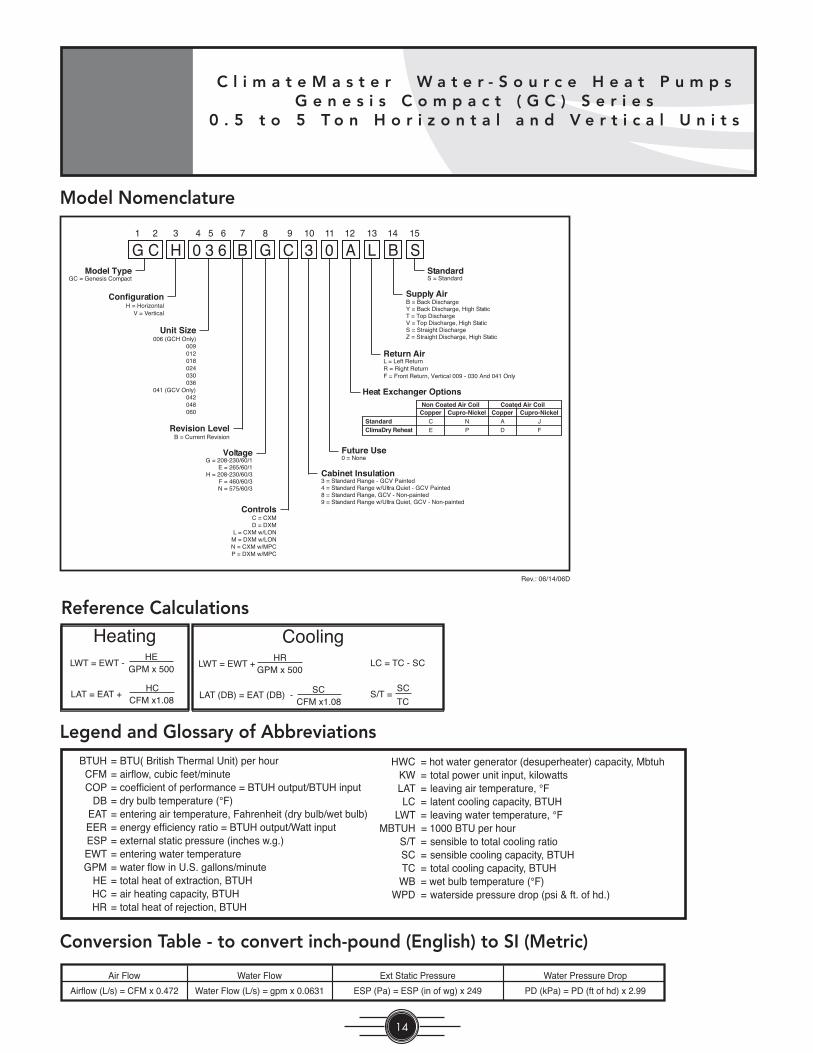
Reference Calculations
BTUH = BTU( British Thermal Unit) per hour CFM = airfl ow, cubic feet/minute COP = coeffi cient of performance = BTUH output/BTUH input DB = dry bulb temperature (°F) EAT = entering air temperature, Fahrenheit (dry bulb/wet bulb) EER = energy effi ciency ratio = BTUH output/Watt input ESP = external static pressure (inches w.g.) EWT = entering water temperature GPM = water fl ow in U.S. gallons/minute HE = total heat of extraction, BTUH HC = air heating capacity, BTUH HR = total heat of rejection, BTUH
HWC = hot water generator (desuperheater) capacity, Mbtuh KW = total power unit input, kilowatts LAT = leaving air temperature, °F LC = latent cooling capacity, BTUH LWT = leaving water temperature, °FMBTUH = 1000 BTU per hour S/T = sensible to total cooling ratio SC = sensible cooling capacity, BTUH TC = total cooling capacity, BTUH WB = wet bulb temperature (°F) WPD = waterside pressure drop (psi & ft. of hd.)
Conversion Table - to convert inch-pound (English) to SI (Metric)
Legend and Glossary of Abbreviations
LWT = EWT -HE
GPM x 500
LAT = EAT +HC
CFM x1.08
LWT = EWT +HR
GPM x 500
LAT (DB) = EAT (DB) -SC
CFM x1.08
LC = TC - SC
S/T =SC
TC
Heating Cooling
Model Nomenclature
G C H B0 3 6 CG 3 0 A L B S1 2 3 4 5 6 7 8 9 10 11 12 13 14 15
GC = Genesis CompactModel Type
H = HorizontalConfiguration
V = Vertical
006 (GCH Only)Unit Size
009012018024030036
041 (GCV Only)042048060
Revision LevelB = Current Revision
Voltage
C = CXMControls
D = DXML = CXM w/LON
M = DXM w/LONN = CXM w/MPCP = DXM w/MPC
3 = Standard Range - GCV PaintedCabinet Insulation
4 = Standard Range w/Ultra Quiet - GCV Painted
0 = NoneFuture Use
Heat Exchanger Options
L = Left ReturnReturn Air
R = Right ReturnF = Front Return, Vertical 009 - 030 And 041 Only
B = Back DischargeSupply Air
Y = Back Discharge, High StaticT = Top DischargeV = Top Discharge, High StaticS = Straight DischargeZ = Straight Discharge, High Static
StandardS = Standard
8 = Standard Range, GCV - Non-painted9 = Standard Range w/Ultra Quiet, GCV - Non-painted
StandardClimaDry Reheat
Non Coated Air Coil Coated Air CoilCopper Cupro-Nickel Copper Cupro-Nickel
C
E
N
P
A
D
J
F
Rev.: 06/14/06D
G = 208-230/60/1E = 265/60/1
H = 208-230/60/3F = 460/60/3N = 575/60/3
T h e S m a r t C h o i c e f o r E n e r g y E f f i c i e n c y
15
T hh e S m a r t C h o i c e f o r E n e r g
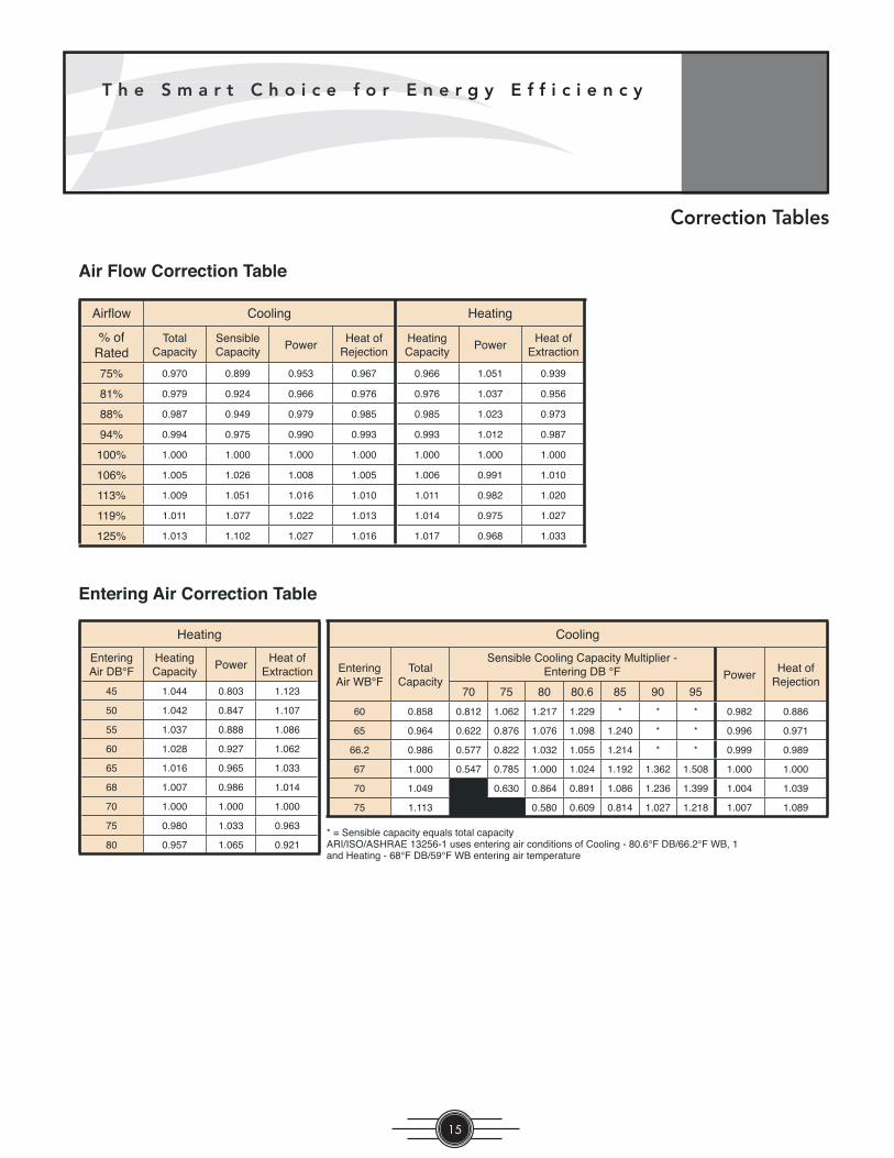
Correction Tables
Air Flow Correction Table
Entering Air Correction Table
Airfl ow Cooling Heating
% ofRated
TotalCapacity
SensibleCapacity
PowerHeat of
RejectionHeatingCapacity
PowerHeat of
Extraction
75% 0.970 0.899 0.953 0.967 0.966 1.051 0.939
81% 0.979 0.924 0.966 0.976 0.976 1.037 0.956
88% 0.987 0.949 0.979 0.985 0.985 1.023 0.973
94% 0.994 0.975 0.990 0.993 0.993 1.012 0.987
100% 1.000 1.000 1.000 1.000 1.000 1.000 1.000
106% 1.005 1.026 1.008 1.005 1.006 0.991 1.010
113% 1.009 1.051 1.016 1.010 1.011 0.982 1.020
119% 1.011 1.077 1.022 1.013 1.014 0.975 1.027
125% 1.013 1.102 1.027 1.016 1.017 0.968 1.033
Cooling
EnteringAir WB°F
TotalCapacity
Sensible Cooling Capacity Multiplier - Entering DB °F Power
Heat ofRejection
70 75 80 80.6 85 90 95
60 0.858 0.812 1.062 1.217 1.229 * * * 0.982 0.886
65 0.964 0.622 0.876 1.076 1.098 1.240 * * 0.996 0.971
66.2 0.986 0.577 0.822 1.032 1.055 1.214 * * 0.999 0.989
67 1.000 0.547 0.785 1.000 1.024 1.192 1.362 1.508 1.000 1.000
70 1.049 0.630 0.864 0.891 1.086 1.236 1.399 1.004 1.039
75 1.113 0.580 0.609 0.814 1.027 1.218 1.007 1.089
* = Sensible capacity equals total capacityARI/ISO/ASHRAE 13256-1 uses entering air conditions of Cooling - 80.6°F DB/66.2°F WB, 1and Heating - 68°F DB/59°F WB entering air temperature
Heating
EnteringAir DB°F
HeatingCapacity
PowerHeat of
Extraction
45 1.044 0.803 1.123
50 1.042 0.847 1.107
55 1.037 0.888 1.086
60 1.028 0.927 1.062
65 1.016 0.965 1.033
68 1.007 0.986 1.014
70 1.000 1.000 1.000
75 0.980 1.033 0.963
80 0.957 1.065 0.921

C l i m a t e M a s t e r W a t e r - S o u r c e H e a t P u m p sG e n e s i s C o m p a c t ( G C ) S e r i e s
0 . 5 t o 5 T o n H o r i z o n t a l a n d V e r t i c a l U n i t s
16
Unit Model Number Des ig na tionGC H = Horizontal Heat Pump GC V = Vertical Heat Pump
Capacity Table IndexGC H/V 006-060 - See Page 17-27.
Glossary of TermsSee Page 14.
Selection Procedure
Step 1 Determine the actual heating and cooling loads at the desired dry bulb and wet bulb conditions.
Step 2 Obtain the following de sign parameters: Entering water temperature, water fl ow rate in GPM, air fl ow in CFM, water fl ow pressure drop and design wet and dry bulb temperatures. Air fl ow CFM should be between 300 and 450 CFM per ton. Unit water pressure drop should be kept as close as possible to each other to make water balancing easier. Go to the ap pro pri ate tables and fi nd the proper indicated water fl ow and water tem per a ture.
Step 3 Select a unit based on total and sensible cooling conditions. Select a unit which is closest to, but no larger than, the actual cooling load.
Step 4 Enter tables at the design water fl ow and water temperature. Read the total and sensible cooling capacities (Note: interpolation is per mis si ble, ex trap o la tion is not).
Step 5 Read the heating capacity. If it exceeds the design criteria it is acceptable. It is quite normal for Water-Source Heat Pumps to be selected on cooling capacity only since the heating output is usually greater than the cooling capacity.
Step 6 Determine the correction factors associated with the variable factors of dry bulb and wet bulb (page 14).
Corrected Total Cooling = tabulated total cooling x wet bulb correction.
Corrected Sensible Cooling = tabulated sensible cooling x wet/dry bulb correction.
Step 7 Compare the corrected capacities to the load re quire ments. Normally if the capacities are within 10% of the loads, the equipment is ac cept able. It is better to undersize than oversize, as undersizing improves humidity control, reduces sound levels and extends the life of the equip ment.
Step 8 When completed, calculate water temperature rise and assess the selection. If the units selected are not within 10% of the load cal cu la tions, then review what effect chang ing the GPM, water temperature and/or air
fl ow and air tem per a ture would have on the corrected capacities. If the desired capacity cannot be achieved, select the next larger or smaller unit and repeat the procedure. Remember, when in doubt, undersize slightly for best performance.
Example Equipment Selection For Cool ing
Step 1 Load Determination:Assume we have determined that the appropriate cooling load at the desired dry bulb 80°F and wet bulb 65°F con di tions is as follows:
Total Cooling ..........................................22,100 BTUHSensible Cooling ......................................16,500 BTUHEntering Air Temp ...... 80°F Dry Bulb / 65°F Wet Bulb
Step 2 Design Conditions:Similarly, we have also obtained the following design pa ram e- ters:
Entering Water Temp ........................................... 90°FWater Flow (Based upon 12°F rise in temp.) 4.5 GPMAir Flow ........................................................700 CFM
Step 3, 4 & 5 HP Selection:After making our preliminary selection (GCH024B), we enter the tables at design water fl ow and water tem per a ture and read Total Cooling, Sens. Cooling and Heat of Rej. ca pac i ties:
Total Cooling ...........................................23,500 BTUHSensible Cooling ......................................17,800 BTUHHeat of Rejection .....................................30,300 BTUH
Step 6 & 7 Entering Air and Airfl ow Corrections:Next, we determine our correction factors. Table Ent Air Air Flow Cor rect ed
Corrected Total Cooling = 23,500 x 0.964 x 0.987 = 22,359Corrected Sens Cooling = 17,800 x 1.076 x 0.949 = 18,176Corrected Heat of Reject = 30,300 x 0.971 x 0.985 = 28,980
Step 8 Water Temperature Rise Calculation & As sess ment:
Actual Temperature Rise 12.9°F
When we compare the Corrected Total Cooling and Corrected Sensible Cooling fi gures with our load re quire ments stated in Step 1, we discover that our selection is within +/- 10% of our sensible load requirement. Fur ther more, we see that our Cor rect ed Total Cooling fi gure is within 259 Btuh of the actual in di cat ed load.
T h e S m a r t C h o i c e f o r E n e r g y E f f i c i e n c y
17
T hh e S m a r t C h o i c e f o r E n e r g
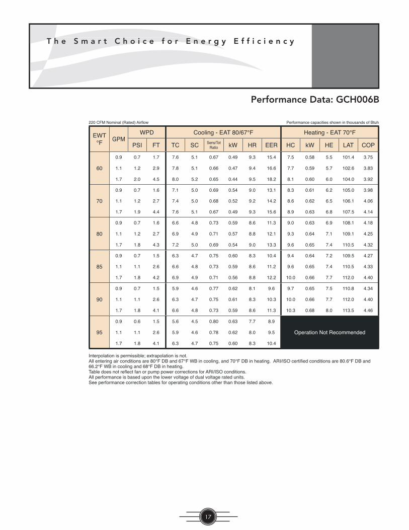
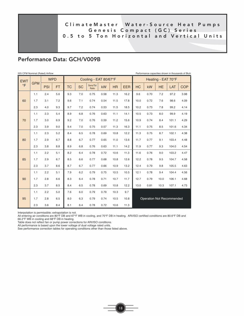
Performance Data: GCH006B
EWT°F
GPMWPD Cooling - EAT 80/67°F Heating - EAT 70°F
PSI FT TC SC Sens/Tot Ratio kW HR EER HC kW HE LAT COP
60
0.9 0.7 1.7 7.6 5.1 0.67 0.49 9.3 15.4 7.5 0.58 5.5 101.4 3.75
1.1 1.2 2.9 7.8 5.1 0.66 0.47 9.4 16.6 7.7 0.59 5.7 102.6 3.83
1.7 2.0 4.5 8.0 5.2 0.65 0.44 9.5 18.2 8.1 0.60 6.0 104.0 3.92
70
0.9 0.7 1.6 7.1 5.0 0.69 0.54 9.0 13.1 8.3 0.61 6.2 105.0 3.98
1.1 1.2 2.7 7.4 5.0 0.68 0.52 9.2 14.2 8.6 0.62 6.5 106.1 4.06
1.7 1.9 4.4 7.6 5.1 0.67 0.49 9.3 15.6 8.9 0.63 6.8 107.5 4.14
80
0.9 0.7 1.6 6.6 4.8 0.73 0.59 8.6 11.3 9.0 0.63 6.9 108.1 4.18
1.1 1.2 2.7 6.9 4.9 0.71 0.57 8.8 12.1 9.3 0.64 7.1 109.1 4.25
1.7 1.8 4.3 7.2 5.0 0.69 0.54 9.0 13.3 9.6 0.65 7.4 110.5 4.32
85
0.9 0.7 1.5 6.3 4.7 0.75 0.60 8.3 10.4 9.4 0.64 7.2 109.5 4.27
1.1 1.1 2.6 6.6 4.8 0.73 0.59 8.6 11.2 9.6 0.65 7.4 110.5 4.33
1.7 1.8 4.2 6.9 4.9 0.71 0.56 8.8 12.2 10.0 0.66 7.7 112.0 4.40
90
0.9 0.7 1.5 5.9 4.6 0.77 0.62 8.1 9.6 9.7 0.65 7.5 110.8 4.34
1.1 1.1 2.6 6.3 4.7 0.75 0.61 8.3 10.3 10.0 0.66 7.7 112.0 4.40
1.7 1.8 4.1 6.6 4.8 0.73 0.59 8.6 11.3 10.3 0.68 8.0 113.5 4.46
95
0.9 0.6 1.5 5.6 4.5 0.80 0.63 7.7 8.9
Operation Not Recommended1.1 1.1 2.6 5.9 4.6 0.78 0.62 8.0 9.5
1.7 1.8 4.1 6.3 4.7 0.75 0.60 8.3 10.4
Interpolation is permissible; extrapolation is not.All entering air conditions are 80°F DB and 67°F WB in cooling, and 70°F DB in heating. ARI/ISO certifi ed conditions are 80.6°F DB and 66.2°F WB in cooling and 68°F DB in heating.Table does not refl ect fan or pump power corrections for ARI/ISO conditions.All performance is based upon the lower voltage of dual voltage rated units.See performance correction tables for operating conditions other than those listed above.
Performance capacities shown in thousands of Btuh220 CFM Nominal (Rated) Airfl ow
C l i m a t e M a s t e r W a t e r - S o u r c e H e a t P u m p sG e n e s i s C o m p a c t ( G C ) S e r i e s
0 . 5 t o 5 T o n H o r i z o n t a l a n d V e r t i c a l U n i t s
18
Performance Data: GCH/V009B
EWT°F
GPMWPD Cooling - EAT 80/67°F Heating - EAT 70°F
PSI FT TC SC Sens/Tot Ratio kW HR EER HC kW HE LAT COP
60
1.1 2.4 5.6 9.3 7.0 0.75 0.58 11.3 16.2 9.6 0.70 7.2 97.2 3.98
1.7 3.1 7.2 9.6 7.1 0.74 0.54 11.5 17.8 10.0 0.72 7.6 98.6 4.09
2.3 4.0 9.3 9.7 7.2 0.74 0.53 11.5 18.5 10.2 0.73 7.8 99.2 4.14
70
1.1 2.3 5.4 8.9 6.8 0.76 0.63 11.1 14.1 10.5 0.73 8.0 99.9 4.19
1.7 3.0 6.9 9.2 7.0 0.76 0.59 11.2 15.6 10.9 0.74 8.4 101.1 4.29
2.3 3.9 9.0 9.4 7.0 0.75 0.57 11.3 16.3 11.1 0.75 8.5 101.6 4.34
80
1.1 2.3 5.2 8.4 6.5 0.78 0.69 10.8 12.2 11.3 0.75 8.7 102.1 4.38
1.7 2.9 6.7 8.8 6.7 0.77 0.65 11.0 13.6 11.7 0.77 9.1 103.4 4.48
2.3 3.8 8.8 8.9 6.8 0.76 0.63 11.1 14.2 11.9 0.77 9.3 104.0 4.54
85
1.1 2.2 5.1 8.2 6.4 0.78 0.72 10.6 11.3 11.6 0.76 9.0 103.2 4.47
1.7 2.9 6.7 8.5 6.6 0.77 0.68 10.8 12.6 12.2 0.78 9.5 104.7 4.58
2.3 3.7 8.6 8.7 6.7 0.77 0.66 10.9 13.2 12.4 0.79 9.8 105.5 4.63
90
1.1 2.2 5.1 7.9 6.2 0.79 0.75 10.5 10.5 12.1 0.78 9.4 104.4 4.56
1.7 2.8 6.6 8.3 6.4 0.78 0.71 10.7 11.7 12.7 0.79 10.0 106.1 4.68
2.3 3.7 8.5 8.4 6.5 0.78 0.69 10.8 12.2 13.0 0.81 10.3 107.1 4.73
95
1.1 2.2 5.0 7.6 6.0 0.79 0.79 10.3 9.7
Operation Not Recommended1.7 2.8 6.5 8.0 6.3 0.79 0.74 10.5 10.8
2.3 3.6 8.4 8.1 6.4 0.78 0.72 10.6 11.3
Interpolation is permissible; extrapolation is not.All entering air conditions are 80°F DB and 67°F WB in cooling, and 70°F DB in heating. ARI/ISO certifi ed conditions are 80.6°F DB and 66.2°F WB in cooling and 68°F DB in heating.Table does not refl ect fan or pump power corrections for ARI/ISO conditions.All performance is based upon the lower voltage of dual voltage rated units.See performance correction tables for operating conditions other than those listed above.
Performance capacities shown in thousands of Btuh325 CFM Nominal (Rated) Airfl ow

T h e S m a r t C h o i c e f o r E n e r g y E f f i c i e n c y
19
T hh e S m a r t C h o i c e f o r E n e r g
Performance Data: GCH/V012B
EWT°F
GPMWPD Cooling - EAT 80/67°F Heating - EAT 70°F
PSI FT TC SC Sens/Tot Ratio kW HR EER HC kW HE LAT COP
60
1.5 2.3 5.3 12.7 9.0 0.71 0.82 15.5 15.5 13.0 1.00 9.5 100.0 3.79
2.3 4.5 10.3 13.1 9.2 0.70 0.77 15.7 17.1 13.6 1.02 10.1 101.6 3.90
3.0 6.4 14.9 13.2 9.2 0.70 0.74 15.8 17.8 13.9 1.03 10.4 102.3 3.95
70
1.5 2.2 5.1 12.1 8.7 0.71 0.90 15.2 13.5 14.4 1.05 10.8 103.2 4.01
2.3 4.3 9.9 12.6 8.9 0.71 0.84 15.5 14.9 15.0 1.07 11.4 104.8 4.11
3.0 6.2 14.3 12.8 9.0 0.71 0.82 15.6 15.6 15.3 1.08 11.7 105.5 4.16
80
1.5 2.1 4.9 11.4 8.3 0.73 0.98 14.7 11.6 15.6 1.09 11.9 106.1 4.19
2.3 4.2 9.7 11.9 8.6 0.72 0.92 15.1 12.9 16.3 1.11 12.5 107.7 4.28
3.0 6.0 13.9 12.1 8.7 0.71 0.90 15.2 13.5 16.6 1.12 12.7 108.3 4.33
85
1.5 2.1 4.9 11.0 8.1 0.73 1.02 14.4 10.7 16.2 1.11 12.4 107.5 4.27
2.3 4.1 9.5 11.5 8.3 0.72 0.96 14.8 12.0 16.8 1.13 13.0 108.9 4.36
3.0 6.0 13.8 11.8 8.5 0.72 0.94 15.0 12.5 17.1 1.14 13.2 109.6 4.40
90
1.5 2.1 4.8 10.5 7.8 0.75 1.07 14.1 9.8 16.7 1.13 12.9 108.7 4.35
2.3 4.1 9.4 11.1 8.1 0.73 1.01 14.5 11.0 17.3 1.14 13.4 110.1 4.44
3.0 5.9 13.6 11.4 8.3 0.73 0.98 14.7 11.6 17.6 1.15 13.7 110.8 4.48
95
1.5 2.1 4.8 10.0 7.6 0.76 1.11 13.8 9.0
Operation Not Recommended2.3 4.0 9.3 10.6 7.9 0.74 1.05 14.2 10.1
3.0 5.8 13.4 10.9 8.0 0.74 1.03 14.4 10.6
Interpolation is permissible; extrapolation is not.All entering air conditions are 80°F DB and 67°F WB in cooling, and 70°F DB in heating. ARI/ISO certifi ed conditions are 80.6°F DB and 66.2°F WB in cooling and 68°F DB in heating.Table does not refl ect fan or pump power corrections for ARI/ISO conditions.All performance is based upon the lower voltage of dual voltage rated units.See performance correction tables for operating conditions other than those listed above.
Performance capacities shown in thousands of Btuh400 CFM Nominal (Rated) Airfl ow

C l i m a t e M a s t e r W a t e r - S o u r c e H e a t P u m p sG e n e s i s C o m p a c t ( G C ) S e r i e s
0 . 5 t o 5 T o n H o r i z o n t a l a n d V e r t i c a l U n i t s
20
Performance Data: GCH/V018B
EWT°F
GPMWPD Cooling - EAT 80/67°F Heating - EAT 70°F
PSI FT TC SC Sens/Tot Ratio kW HR EER HC kW HE LAT COP
60
2.3 2.1 4.8 20.2 14.8 0.73 1.37 24.8 14.7 19.9 1.54 14.6 100.7 3.78
3.4 3.0 7.0 20.9 15.1 0.72 1.28 25.3 16.4 20.7 1.57 15.4 102.0 3.87
4.5 4.3 9.8 21.3 15.2 0.71 1.24 25.6 17.2 21.1 1.58 15.7 102.6 3.90
70
2.3 2.0 4.6 19.3 14.4 0.75 1.48 24.4 13.1 21.6 1.60 16.1 103.3 3.95
3.4 2.9 6.7 20.0 14.7 0.74 1.39 24.7 14.3 22.4 1.63 16.8 104.6 4.03
4.5 4.1 9.5 20.3 14.9 0.73 1.36 24.9 14.9 22.7 1.64 17.1 105.1 4.06
80
2.3 1.9 4.5 18.3 13.8 0.75 1.58 23.7 11.5 23.1 1.65 17.4 105.6 4.09
3.4 2.8 6.5 19.1 14.3 0.75 1.50 24.2 12.7 23.8 1.68 18.1 106.8 4.15
4.5 4.0 9.2 19.4 14.4 0.74 1.47 24.4 13.2 24.1 1.69 18.3 107.2 4.17
85
2.3 1.9 4.4 17.6 13.4 0.76 1.63 23.1 10.8 23.7 1.68 18.0 106.6 4.14
3.4 2.8 6.4 18.6 14.0 0.75 1.56 23.9 11.9 24.4 1.71 18.6 107.6 4.19
4.5 3.9 9.1 18.9 14.2 0.75 1.52 24.1 12.4 24.7 1.72 18.8 108.1 4.20
90
2.3 1.9 4.4 16.7 12.9 0.77 1.67 22.4 10.0 24.3 1.70 18.5 107.5 4.18
3.4 2.7 6.3 17.9 13.6 0.76 1.61 23.4 11.2 24.9 1.73 19.0 108.5 4.22
4.5 3.9 9.0 18.3 13.8 0.75 1.58 23.7 11.6 25.3 1.74 19.4 109.0 4.25
95
2.3 1.9 4.3 15.7 12.3 0.78 1.72 21.5 9.1
Operation Not Recommended3.4 2.7 6.3 17.1 13.1 0.77 1.65 22.7 10.3
4.5 3.8 8.9 17.6 13.4 0.76 1.63 23.2 10.8
Interpolation is permissible; extrapolation is not.All entering air conditions are 80°F DB and 67°F WB in cooling, and 70°F DB in heating. ARI/ISO certifi ed conditions are 80.6°F DB and 66.2°F WB in cooling and 68°F DB in heating.Table does not refl ect fan or pump power corrections for ARI/ISO conditions.All performance is based upon the lower voltage of dual voltage rated units.See performance correction tables for operating conditions other than those listed above.
Performance capacities shown in thousands of Btuh600 CFM Nominal (Rated) Airfl ow

T h e S m a r t C h o i c e f o r E n e r g y E f f i c i e n c y
21
T hh e S m a r t C h o i c e f o r E n e r g
Performance Data: GCH/V024B
EWT°F
GPMWPD Cooling - EAT 80/67°F Heating - EAT 70°F
PSI FT TC SC Sens/Tot Ratio kW HR EER HC kW HE LAT COP
60
3.0 2.0 4.6 25.5 19.1 0.75 1.71 31.3 14.9 26.3 1.74 20.3 100.4 4.42
4.5 3.8 8.9 25.8 19.2 0.74 1.62 31.4 15.9 27.4 1.78 21.4 101.8 4.51
6.0 6.4 14.9 26.0 19.3 0.74 1.58 31.4 16.5 28.0 1.80 21.9 102.4 4.55
70
3.0 1.9 4.4 24.9 18.7 0.75 1.85 31.2 13.5 28.6 1.83 22.4 103.1 4.59
4.5 3.7 8.5 25.3 19.0 0.75 1.76 31.3 14.4 29.7 1.87 23.3 104.3 4.66
6.0 6.2 14.3 25.5 19.1 0.75 1.71 31.3 14.9 30.1 1.89 23.7 104.9 4.68
80
3.0 1.9 4.3 23.9 18.0 0.75 1.97 30.6 12.1 30.5 1.90 24.0 105.3 4.70
4.5 3.6 8.3 24.6 18.5 0.75 1.89 31.0 13.0 31.3 1.94 24.7 106.2 4.73
6.0 6.0 13.9 24.9 18.7 0.75 1.84 31.2 13.5 31.6 1.95 25.0 106.6 4.74
85
3.0 1.8 4.2 23.2 17.6 0.76 2.03 30.2 11.4 31.2 1.93 24.6 106.1 4.73
4.5 3.6 8.2 24.1 18.2 0.75 1.95 30.8 12.4 31.9 1.97 25.1 106.9 4.75
6.0 6.0 13.8 24.5 18.4 0.75 1.91 31.0 12.8 32.1 1.98 25.3 107.2 4.75
90
3.0 1.8 4.2 22.4 17.2 0.77 2.08 29.5 10.8 31.8 1.96 25.1 106.8 4.75
4.5 3.5 8.1 23.5 17.8 0.76 2.01 30.3 11.7 32.3 1.99 25.5 107.3 4.75
6.0 5.9 13.6 23.9 18.1 0.75 1.97 30.6 12.1 32.4 2.00 25.6 107.5 4.74
95
3.0 1.8 4.1 21.5 16.6 0.77 2.13 28.7 10.1
Operation Not Recommended4.5 3.5 8.0 22.7 17.3 0.76 2.07 29.8 11.0
6.0 5.8 13.4 23.2 17.6 0.76 2.03 30.2 11.5
Interpolation is permissible; extrapolation is not.All entering air conditions are 80°F DB and 67°F WB in cooling, and 70°F DB in heating. ARI/ISO certifi ed conditions are 80.6°F DB and 66.2°F WB in cooling and 68°F DB in heating.Table does not refl ect fan or pump power corrections for ARI/ISO conditions.All performance is based upon the lower voltage of dual voltage rated units.See performance correction tables for operating conditions other than those listed above.
Performance capacities shown in thousands of Btuh800 CFM Nominal (Rated) Airfl ow

C l i m a t e M a s t e r W a t e r - S o u r c e H e a t P u m p sG e n e s i s C o m p a c t ( G C ) S e r i e s
0 . 5 t o 5 T o n H o r i z o n t a l a n d V e r t i c a l U n i t s
22
Performance Data: GCH/V030B
EWT°F
GPMWPD Cooling - EAT 80/67°F Heating - EAT 70°F
PSI FT TC SC Sens/Tot Ratio kW HR EER HC kW HE LAT COP
60
3.0 2.0 4.6 25.5 19.1 0.75 1.71 31.3 14.9 26.3 1.74 20.3 100.4 4.42
4.5 3.8 8.9 25.8 19.2 0.74 1.62 31.4 15.9 27.4 1.78 21.4 101.8 4.51
6.0 6.4 14.9 26.0 19.3 0.74 1.58 31.4 16.5 28.0 1.80 21.9 102.4 4.55
70
3.0 1.9 4.4 24.9 18.7 0.75 1.85 31.2 13.5 28.6 1.83 22.4 103.1 4.59
4.5 3.7 8.5 25.3 19.0 0.75 1.76 31.3 14.4 29.7 1.87 23.3 104.3 4.66
6.0 6.2 14.3 25.5 19.1 0.75 1.71 31.3 14.9 30.1 1.89 23.7 104.9 4.68
80
3.0 1.9 4.3 23.9 18.0 0.75 1.97 30.6 12.1 30.5 1.90 24.0 105.3 4.70
4.5 3.6 8.3 24.6 18.5 0.75 1.89 31.0 13.0 31.3 1.94 24.7 106.2 4.73
6.0 6.0 13.9 24.9 18.7 0.75 1.84 31.2 13.5 31.6 1.95 25.0 106.6 4.74
85
3.0 1.8 4.2 23.2 17.6 0.76 2.03 30.2 11.4 31.2 1.93 24.6 106.1 4.73
4.5 3.6 8.2 24.1 18.2 0.75 1.95 30.8 12.4 31.9 1.97 25.1 106.9 4.75
6.0 6.0 13.8 24.5 18.4 0.75 1.91 31.0 12.8 32.1 1.98 25.3 107.2 4.75
90
3.0 1.8 4.2 22.4 17.2 0.77 2.08 29.5 10.8 31.8 1.96 25.1 106.8 4.75
4.5 3.5 8.1 23.5 17.8 0.76 2.01 30.3 11.7 32.3 1.99 25.5 107.3 4.75
6.0 5.9 13.6 23.9 18.1 0.75 1.97 30.6 12.1 32.4 2.00 25.6 107.5 4.74
95
3.0 1.8 4.1 21.5 16.6 0.77 2.13 28.7 10.1
Operation Not Recommended4.5 3.5 8.0 22.7 17.3 0.76 2.07 29.8 11.0
6.0 5.8 13.4 23.2 17.6 0.76 2.03 30.2 11.5
Interpolation is permissible; extrapolation is not.All entering air conditions are 80°F DB and 67°F WB in cooling, and 70°F DB in heating. ARI/ISO certifi ed conditions are 80.6°F DB and 66.2°F WB in cooling and 68°F DB in heating.Table does not refl ect fan or pump power corrections for ARI/ISO conditions.All performance is based upon the lower voltage of dual voltage rated units.See performance correction tables for operating conditions other than those listed above.
Performance capacities shown in thousands of Btuh800 CFM Nominal (Rated) Airfl ow

T h e S m a r t C h o i c e f o r E n e r g y E f f i c i e n c y
23
T hh e S m a r t C h o i c e f o r E n e r g
Performance Data: GCH/V036B
EWT°F
GPMWPD Cooling - EAT 80/67°F Heating - EAT 70°F
PSI FT TC SC Sens/Tot Ratio kW HR EER HC kW HE LAT COP
60
4.5 1.8 4.1 38.2 26.8 0.70 2.74 47.6 14.0 39.0 2.94 28.9 100.1 3.88
6.8 3.2 7.4 39.0 26.9 0.69 2.58 47.8 15.1 41.4 3.03 31.0 101.9 4.00
9.0 5.1 11.8 39.3 27.1 0.69 2.50 47.8 15.7 42.6 3.07 32.1 102.9 4.06
70
4.5 1.7 3.9 36.6 26.3 0.72 2.95 46.6 12.4 43.9 3.12 33.3 103.9 4.12
6.8 3.1 7.2 37.8 26.7 0.71 2.80 47.3 13.5 46.2 3.21 35.2 105.6 4.22
9.0 4.9 11.3 38.3 26.8 0.70 2.72 47.6 14.1 47.2 3.25 36.1 106.4 4.26
80
4.5 1.7 3.8 34.4 25.6 0.74 3.15 45.1 10.9 47.9 3.28 36.7 107.0 4.28
6.8 3.0 7.0 35.9 26.2 0.73 3.01 46.2 11.9 49.7 3.36 38.2 108.3 4.34
9.0 4.8 11.0 36.7 26.4 0.72 2.94 46.7 12.5 50.5 3.40 38.9 108.9 4.35
85
4.5 1.6 3.8 33.1 25.0 0.76 3.24 44.1 10.2 49.5 3.35 38.1 108.2 4.33
6.8 3.0 6.9 34.8 25.8 0.74 3.11 45.4 11.2 50.9 3.42 39.3 109.3 4.36
9.0 4.7 10.9 35.6 26.0 0.73 3.05 46.0 11.7 51.5 3.45 39.7 109.7 4.37
90
4.5 1.6 3.7 31.6 24.3 0.77 3.34 43.0 9.5 50.8 3.41 39.1 109.2 4.36
6.8 2.9 6.8 33.5 25.2 0.75 3.21 44.5 10.4 51.8 3.47 39.9 110.0 4.37
9.0 4.6 10.7 34.4 25.6 0.74 3.15 45.1 10.9 52.1 3.50 40.2 110.2 4.36
95
4.5 1.6 3.7 30.1 23.5 0.78 3.43 41.8 8.8
Operation Not Recommended6.8 2.9 6.7 32.0 24.6 0.77 3.31 43.3 9.7
9.0 4.6 10.6 33.0 25.0 0.76 3.25 44.1 10.2
Interpolation is permissible; extrapolation is not.All entering air conditions are 80°F DB and 67°F WB in cooling, and 70°F DB in heating. ARI/ISO certifi ed conditions are 80.6°F DB and 66.2°F WB in cooling and 68°F DB in heating.Table does not refl ect fan or pump power corrections for ARI/ISO conditions.All performance is based upon the lower voltage of dual voltage rated units.See performance correction tables for operating conditions other than those listed above.
Performance capacities shown in thousands of Btuh1200 CFM Nominal (Rated) Airfl ow

C l i m a t e M a s t e r W a t e r - S o u r c e H e a t P u m p sG e n e s i s C o m p a c t ( G C ) S e r i e s
0 . 5 t o 5 T o n H o r i z o n t a l a n d V e r t i c a l U n i t s
24
Performance Data: GCV041B
EWT°F
GPMWPD Cooling - EAT 80/67°F Heating - EAT 70°F
PSI FT TC SC Sens/Tot Ratio kW HR EER HC kW HE LAT COP
60
5.3 1.0 2.2 40.0 29.0 0.73 2.78 49.4 14.4 43.1 3.21 32.2 100.1 3.93
7.9 2.2 5.1 40.5 29.0 0.72 2.67 49.6 15.2 44.7 3.28 33.5 101.2 3.99
10.5 4.0 9.3 40.9 29.0 0.71 2.62 49.8 15.6 45.5 3.32 34.1 101.8 4.02
70
5.3 0.9 2.1 39.1 29.0 0.74 3.00 49.4 13.1 46.6 3.37 35.1 102.6 4.06
7.9 2.1 5.0 39.7 29.0 0.73 2.86 49.4 13.9 48.1 3.43 36.3 103.6 4.10
10.5 3.9 8.9 39.9 29.0 0.73 2.79 49.4 14.3 48.8 3.46 36.9 104.1 4.13
80
5.3 0.9 2.1 37.9 28.4 0.75 3.24 49.0 11.7 49.6 3.50 37.6 104.7 4.15
7.9 2.1 4.8 38.8 28.9 0.75 3.09 49.3 12.5 50.8 3.56 38.7 105.5 4.19
10.5 3.8 8.7 39.1 29.0 0.74 3.01 49.4 13.0 51.4 3.58 39.2 106.0 4.21
85
5.3 0.9 2.0 37.0 27.8 0.75 3.36 48.5 11.0 50.9 3.56 38.7 105.5 4.19
7.9 2.1 4.8 38.1 28.5 0.75 3.21 49.1 11.9 52.0 3.61 39.7 106.3 4.22
10.5 3.7 8.6 38.5 28.8 0.75 3.13 49.2 12.3 52.6 3.64 40.1 106.7 4.23
90
5.3 0.9 2.0 35.9 27.1 0.75 3.48 47.7 10.3 52.0 3.61 39.7 106.3 4.22
7.9 2.0 4.7 37.3 27.9 0.75 3.33 48.6 11.2 53.0 3.66 40.5 107.1 4.25
10.5 3.7 8.5 37.8 28.3 0.75 3.26 48.9 11.6 53.5 3.68 40.9 107.4 4.26
95
5.3 0.9 2.0 34.4 26.3 0.76 3.58 46.7 9.6
Operation Not Recommended7.9 2.0 4.6 36.2 27.3 0.75 3.45 47.9 10.5
10.5 3.6 8.4 36.9 27.7 0.75 3.38 48.4 10.9
Interpolation is permissible; extrapolation is not.All entering air conditions are 80°F DB and 67°F WB in cooling, and 70°F DB in heating. ARI/ISO certifi ed conditions are 80.6°F DB and 66.2°F WB in cooling and 68°F DB in heating.Table does not refl ect fan or pump power corrections for ARI/ISO conditions.All performance is based upon the lower voltage of dual voltage rated units.See performance correction tables for operating conditions other than those listed above.
Performance capacities shown in thousands of Btuh1325 CFM Nominal (Rated) Airfl ow

T h e S m a r t C h o i c e f o r E n e r g y E f f i c i e n c y
25
T hh e S m a r t C h o i c e f o r E n e r g
Performance Data: GCH/V042B
EWT°F
GPMWPD Cooling - EAT 80/67°F Heating - EAT 70°F
PSI FT TC SC Sens/Tot Ratio kW HR EER HC kW HE LAT COP
60
5.3 1.0 2.4 43.2 31.0 0.72 3.03 53.5 14.3 46.8 3.47 34.9 102.1 3.95
8.0 2.7 6.2 43.8 31.0 0.71 2.89 53.6 15.2 48.9 3.58 36.7 103.5 4.00
11.0 5.5 12.7 44.2 31.0 0.70 2.84 53.9 15.6 50.0 3.63 37.6 104.3 4.04
70
5.3 1.0 2.3 42.3 30.8 0.73 3.29 53.5 12.8 51.2 3.69 38.7 105.1 4.07
8.0 2.6 6.0 42.9 30.9 0.72 3.11 53.5 13.8 53.3 3.79 40.4 106.6 4.13
11.0 5.3 12.2 43.2 31.0 0.72 3.02 53.5 14.3 54.4 3.83 41.3 107.3 4.16
80
5.3 1.0 2.2 40.8 30.2 0.74 3.58 53.0 11.4 55.1 3.87 42.0 107.8 4.18
8.0 2.5 5.8 41.9 30.7 0.73 3.38 53.4 12.4 57.0 3.95 43.6 109.1 4.24
11.0 5.2 11.9 42.3 30.8 0.73 3.28 53.5 12.9 58.0 3.98 44.4 109.8 4.26
85
5.3 1.0 2.2 39.6 29.7 0.75 3.72 52.3 10.7 56.9 3.94 43.4 109.0 4.23
8.0 2.5 5.8 41.1 30.4 0.74 3.53 53.1 11.6 58.6 4.01 45.0 110.2 4.29
11.0 5.1 11.8 41.6 30.6 0.73 3.43 53.3 12.1 59.5 4.04 45.7 110.8 4.32
90
5.3 0.9 2.2 38.2 29.0 0.76 3.85 51.3 9.9 58.4 4.00 44.8 110.1 4.28
8.0 2.5 5.7 40.0 29.9 0.75 3.67 52.6 10.9 60.1 4.06 46.2 111.2 4.34
11.0 5.0 11.6 40.8 30.2 0.74 3.58 53.0 11.4 60.8 4.08 46.9 111.7 4.37
95
5.3 0.9 2.2 36.4 28.0 0.77 3.96 49.9 9.2
Operation Not Recommended8.0 2.4 5.6 38.7 29.2 0.76 3.81 51.7 10.1
11.0 5.0 11.5 39.6 29.7 0.75 3.72 52.3 10.6
Interpolation is permissible; extrapolation is not.All entering air conditions are 80°F DB and 67°F WB in cooling, and 70°F DB in heating. ARI/ISO certifi ed conditions are 80.6°F DB and 66.2°F WB in cooling and 68°F DB in heating.Table does not refl ect fan or pump power corrections for ARI/ISO conditions.All performance is based upon the lower voltage of dual voltage rated units.See performance correction tables for operating conditions other than those listed above.
Performance capacities shown in thousands of Btuh1350 CFM Nominal (Rated) Airfl ow

C l i m a t e M a s t e r W a t e r - S o u r c e H e a t P u m p sG e n e s i s C o m p a c t ( G C ) S e r i e s
0 . 5 t o 5 T o n H o r i z o n t a l a n d V e r t i c a l U n i t s
26
Performance Data: GCH/V048B
EWT°F
GPMWPD Cooling - EAT 80/67°F Heating - EAT 70°F
PSI FT TC SC Sens/Tot Ratio kW HR EER HC kW HE LAT COP
60
6.0 1.2 2.9 50.2 35.8 0.71 3.67 62.7 13.7 52.1 3.70 39.5 100.1 4.13
9.0 2.9 6.7 50.9 36.1 0.71 3.48 62.8 14.6 54.6 3.79 41.7 101.6 4.22
12.0 5.3 12.3 51.2 36.3 0.71 3.39 62.8 15.1 56.0 3.84 42.9 102.4 4.27
70
6.0 1.2 2.8 48.8 35.4 0.73 3.96 62.3 12.3 57.4 3.89 44.1 103.2 4.32
9.0 2.8 6.5 49.8 35.6 0.72 3.76 62.6 13.3 59.9 3.98 46.3 104.6 4.41
12.0 5.1 11.8 50.2 35.8 0.71 3.66 62.7 13.7 61.1 4.02 47.4 105.4 4.45
80
6.0 1.2 2.7 46.6 34.8 0.75 4.25 61.1 11.0 62.0 4.05 48.2 105.9 4.48
9.0 2.7 6.3 48.2 35.3 0.73 4.05 62.0 11.9 64.2 4.13 50.1 107.1 4.56
12.0 5.0 11.5 48.8 35.4 0.73 3.95 62.3 12.4 65.2 4.16 51.0 107.8 4.60
85
6.0 1.2 2.7 45.2 34.3 0.76 4.38 60.2 10.3 64.0 4.12 49.9 107.0 4.55
9.0 2.7 6.2 47.1 34.9 0.74 4.20 61.4 11.2 66.0 4.18 51.7 108.2 4.62
12.0 4.9 11.3 47.9 35.2 0.73 4.10 61.8 11.7 66.9 4.21 52.6 108.7 4.66
90
6.0 1.1 2.6 43.5 33.5 0.77 4.51 58.9 9.7 65.7 4.18 51.5 108.0 4.61
9.0 2.7 6.1 45.7 34.5 0.75 4.34 60.5 10.5 67.6 4.23 53.1 109.1 4.68
12.0 4.8 11.2 46.7 34.8 0.75 4.24 61.1 11.0 68.4 4.25 53.9 109.6 4.71
95
6.0 1.1 2.6 41.6 32.6 0.78 4.62 57.4 9.0
Operation Not Recommended9.0 2.6 6.1 44.1 33.8 0.77 4.47 59.3 9.9
12.0 4.8 11.0 45.2 34.3 0.76 4.38 60.2 10.3
Interpolation is permissible; extrapolation is not.All entering air conditions are 80°F DB and 67°F WB in cooling, and 70°F DB in heating. ARI/ISO certifi ed conditions are 80.6°F DB and 66.2°F WB in cooling and 68°F DB in heating.Table does not refl ect fan or pump power corrections for ARI/ISO conditions.All performance is based upon the lower voltage of dual voltage rated units.See performance correction tables for operating conditions other than those listed above.
Performance capacities shown in thousands of Btuh1600 CFM Nominal (Rated) Airfl ow

T h e S m a r t C h o i c e f o r E n e r g y E f f i c i e n c y
27
T hh e S m a r t C h o i c e f o r E n e r g
Performance Data: GCH/V060B
EWT°F
GPMWPD Cooling - EAT 80/67°F Heating - EAT 70°F
PSI FT TC SC Sens/Tot Ratio kW HR EER HC kW HE LAT COP
60
7.5 4.4 10.1 60.5 43.1 0.71 4.36 75.4 13.9 63.0 5.02 45.9 99.2 3.68
11.3 7.6 17.5 61.2 43.2 0.71 4.17 75.5 14.7 67.4 5.17 49.8 101.2 3.82
15.0 11.5 26.7 61.6 43.3 0.70 4.08 75.5 15.1 69.8 5.25 51.9 102.3 3.90
70
7.5 4.2 9.7 59.0 42.9 0.73 4.68 74.9 12.6 72.6 5.34 54.4 103.6 3.98
11.3 7.3 16.9 60.1 43.1 0.72 4.46 75.3 13.5 77.0 5.49 58.2 105.6 4.11
15.0 11.1 25.6 60.5 43.2 0.71 4.36 75.4 13.9 79.2 5.56 60.2 106.6 4.17
80
7.5 4.1 9.4 56.8 42.4 0.75 5.04 74.0 11.3 80.6 5.61 61.5 107.3 4.21
11.3 7.1 16.4 58.3 42.8 0.73 4.80 74.7 12.2 84.4 5.74 64.8 109.1 4.31
15.0 10.8 25.0 59.0 42.9 0.73 4.68 74.9 12.6 86.2 5.80 66.4 109.9 4.35
85
7.5 4.0 9.3 55.4 42.0 0.76 5.23 73.3 10.6 83.9 5.73 64.4 108.9 4.30
11.3 7.0 16.2 57.2 42.5 0.74 4.98 74.1 11.5 87.3 5.84 67.4 110.4 4.38
15.0 10.7 24.6 57.9 42.7 0.74 4.86 74.5 11.9 88.7 5.89 68.7 111.1 4.42
90
7.5 4.0 9.2 53.9 41.4 0.77 5.44 72.4 9.9 86.8 5.82 66.9 110.2 4.37
11.3 6.9 16.0 55.8 42.1 0.75 5.17 73.5 10.8 89.5 5.91 69.4 111.5 4.44
15.0 10.5 24.3 56.7 42.4 0.75 5.04 73.9 11.2 90.6 5.95 70.3 112.0 4.46
95
7.5 3.9 9.1 52.1 40.5 0.78 5.66 71.4 9.2
Operation Not Recommended11.3 6.8 15.8 54.3 41.6 0.77 5.38 72.7 10.1
15.0 10.4 24.0 55.3 42.0 0.76 5.24 73.2 10.6
Interpolation is permissible; extrapolation is not.All entering air conditions are 80°F DB and 67°F WB in cooling, and 70°F DB in heating. ARI/ISO certifi ed conditions are 80.6°F DB and 66.2°F WB in cooling and 68°F DB in heating.Table does not refl ect fan or pump power corrections for ARI/ISO conditions.All performance is based upon the lower voltage of dual voltage rated units.See performance correction tables for operating conditions other than those listed above.
Performance capacities shown in thousands of Btuh2000 CFM Nominal (Rated) Airfl ow

C l i m a t e M a s t e r W a t e r - S o u r c e H e a t P u m p sG e n e s i s C o m p a c t ( G C ) S e r i e s
0 . 5 t o 5 T o n H o r i z o n t a l a n d V e r t i c a l U n i t s
28
Physical Data
Model 006 009 012 018 024 030 036 041 042 048 060
Compressor (1 Each) Rotary Recipricating Scroll
Factory Charge Vertical R22 (oz) [kg] - 14 [.40] 14 [.40] 25 [.74] 38 [1.08] 37 [1.05] 42 [1.19] 50 [1.42] 51 [1.87] 66 [1.87] 74 [2.10]
Factory Charge Horizontal R22 (oz) [kg] 14 [.40] 14 [.40] 14 [.40] 25 [.74] 38 [1.08] 37 [1.05] 41 [1.16] - 51 [1.87] 66 [1.87] 74 [2.10]
PSC Fan Motor & Blower (3 Speeds)
Fan Motor (hp) [W] 1/25 [30] 1/10 [75] 1/10 [75] 1/6 [124] 1/4 [187] 3/4 [560] 1/2 [373] 3/4 [560] 3/4 [560] 3/4 [560] 1 [746]
Blower Wheel Size (dia x w) - (in) [mm]
5 x 5[127 x 127]
5 x 5[127 x 127]
6 x 5[152 x 127]
8 x 7[208 x 178]
9 x 7[229 x 178]
9 x 7[229 x 178]
9 x 8[229 x 203]
9 x 8[229 x 203]
9 x 8[229 x 203]
10 x 10[254 x 254]
10 x 10[254 x 254]
Water Connection Size
IPT (in) 1/2 1/2 1/2 1/2 3/4 3/4 3/4 3/4 3/4 1 1
Coax Volume
Volume (US Gallons) [liters] 0.123[0.47]
0.143[0.54]
0.167[0.63]
0.286[1.08]
0.286[1.08]
0.323[1.22]
0.526[1.99]
0.738[2.79]
0.890[3.37]
0.738[2.79]
0.939[3.55]
Vertical Upfl ow
Air Coil Dimensions (h x w) - (in) [mm] -10 x 15
[254 x 381]10 x 15
[254 x 381]20 x 17.25[508 x 438]
20 x 17.25[508 x 438]
20 x 17.25[508 x 438]
24 x 21.75[610 x 552]
20 x 17.25[508 x 438]
24 x 21.75[610 x 552]
24 x 28.25[610 x 718]
24 x 28.25[610 x 718]
Standard Filter - 1” [25.4mm]Throwaway, qty (in) [mm]
-10 x 18
[254 x 457]10 x 18
[254 x 457]20 x 20
[508 x 508]20 x 20
[508 x 508]20 x 20
[508 x 508]24 x 24
[610 x 610]20 x 20
[508 x 508]24 x 24
[610 x 610]
1 - 14 x 24,1 - 18 x 24[356 x 610],[457 x 610]
1 - 14 x 24,1 - 18 x 24[356 x 610],[457 x 610]
Horizontal
Air Coil Dimensions (h x w) - (in) [mm] 10 x 15[254 x 381]
10 x 15[254 x 381]
10 x 15[254 x 381]
16 x 22[406 x 559]
16 x 22[406 x 559]
16 x 22[406 x 559]
20 x 25[508 x 635]
-20 x 25
[508 x 635]20 x 35
[508 x 889]20 x 35
[508 x 889]
Standard Filter - 1” [25.4mm]Throwaway, qty (in) [mm]
10 x 18[254 x 457]
10 x 18[254 x 457]
10 x 18[254 x 457]
16 x 25[406 x 635]
16 x 25[406 x 635]
16 x 25[406 x 635]
20 x 28 or2 - 20 x 14[508 x 711]or [2 - 508
x 356]
-
20 x 28 or2 - 20 x 14[508 x 711]or [2 - 508
x 356]
1 - 20 x 24,1 - 20 x 14[508 x 610],[508 x 356]
1 - 20 x 24,1 - 20 x 14[508 x 610],[508 x 356]
Weight - Operating, (lbs) [kg] 103 [47] 105 [48] 114 [52] 181 [82] 189 [86] 197 [89] 203 [92] 207 [94] 218 [99] 263 [119] 278 [126]
Weight - Packaged, (lbs) [kg] 113 [51] 115 [52] 124 [56] 186 [84] 194 [88] 202 [92] 209 [95] 212 [96] 224 [102] 270 [122] 285 [129]
All units have grommet compressor mountings, and 1/2” [12.2mm] & 3/4” [19.mm] electrical knockouts.

T h e S m a r t C h o i c e f o r E n e r g y E f f i c i e n c y
29
T hh e S m a r t C h o i c e f o r E n e r g
GCH006 - 012 Dimensions
Notes:1. While clear access to all removable panels is not required, installer should take care to comply with all building
codes and allow adequate clearance for future fi eld service. 2. Horizontal units shipped with fi lter bracket only. This bracket should be removed for return duct connection3. Discharge fl ange and hanger brackets are factory installed.Legend:CAP = Control Access Panel BSP = Blower Service Panel (this panel requires adequate service access)CSP = Compressor Access Panel ASP = Alternative Service Panel
Fro
nt
Front
Left ReturnBack Discharge
Left Return, Left View
Right Return, Right View
Left Return, Straight Discharge
Right Return, Straight Discharge
Right ReturnBack Discharge
Note: Choose either straight or back discharge
Straight Discharge
Back Discharge
2ft [61cm]
Optional
Service Access
2ft [61cm]Service Access

C l i m a t e M a s t e r W a t e r - S o u r c e H e a t P u m p sG e n e s i s C o m p a c t ( G C ) S e r i e s
0 . 5 t o 5 T o n H o r i z o n t a l a n d V e r t i c a l U n i t s
30
GCH018 Dimensions
Notes:1. While clear access to all removable panels
is not required, installer should take care to comply with all building codes and allow adequate clearance for future fi eld service.
2. Horizontal units shipped with fi lter bracket only. This bracket should be removed for return duct connection
3. Discharge fl ange and hanger brackets are factory installed.
Fro
nt
Front
Left ReturnBack Discharge
Left Return, Left View
Right Return, Right View
Left Return, Straight Discharge
Right Return, Straight Discharge
Right ReturnBack Discharge
Note: Choose either straight or back discharge
Straight Discharge
Back Discharge
2ft [61cm]
Optional
Service Access
2ft [61cm]Service Access
Legend:CAP = Control Access Panel BSP = Blower Service Panel(this panel requires adequate service access)CSP = Compressor Access PanelASP = Alternative Service Panel
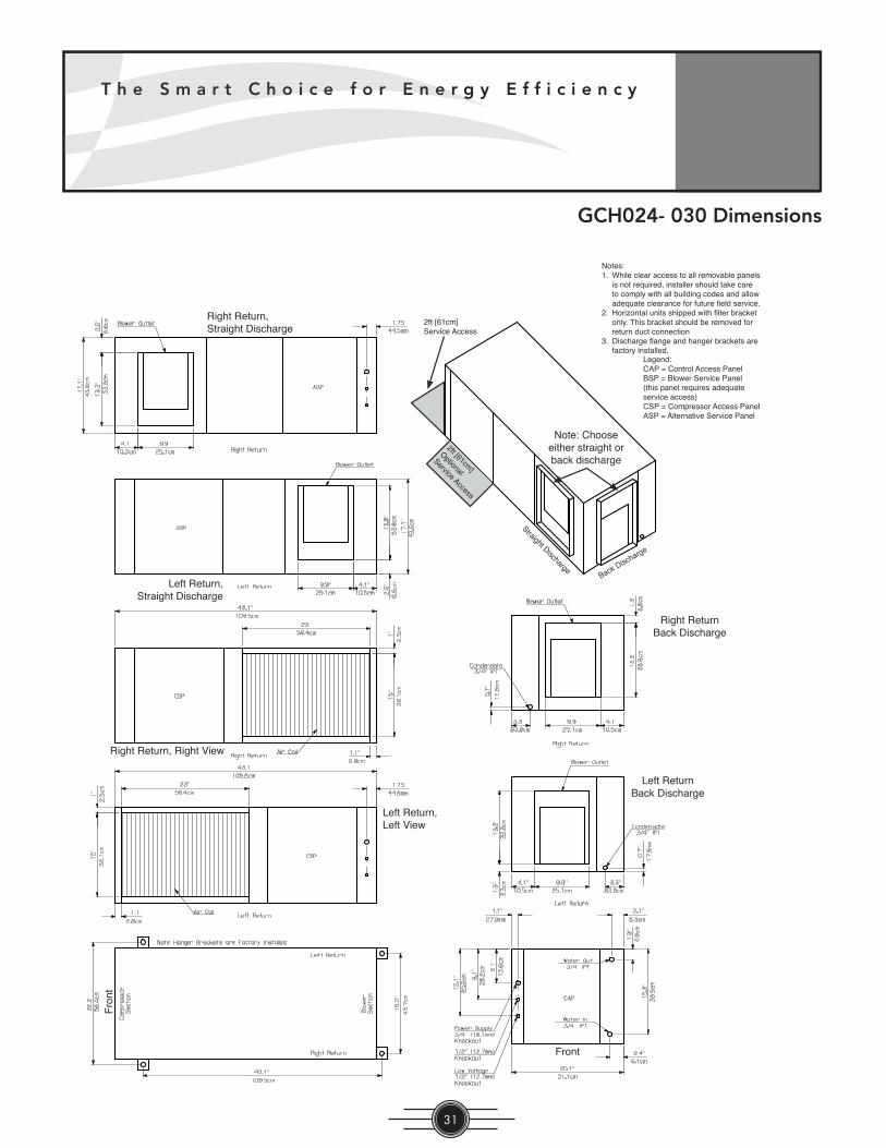
T h e S m a r t C h o i c e f o r E n e r g y E f f i c i e n c y
31
T hh e S m a r t C h o i c e f o r E n e r g
GCH024- 030 Dimensions
Fro
nt
Front
Left ReturnBack Discharge
Left Return, Left View
Right Return, Right View
Left Return, Straight Discharge
Right Return, Straight Discharge
Right ReturnBack Discharge
Note: Choose either straight or back discharge
Straight DischargeBack Discharge
2ft [61cm]
Optional
Service Access
2ft [61cm]Service Access
Notes:1. While clear access to all removable panels
is not required, installer should take care to comply with all building codes and allow adequate clearance for future fi eld service.
2. Horizontal units shipped with fi lter bracket only. This bracket should be removed for return duct connection
3. Discharge fl ange and hanger brackets are factory installed.
Legend:CAP = Control Access Panel BSP = Blower Service Panel(this panel requires adequate service access)CSP = Compressor Access PanelASP = Alternative Service Panel
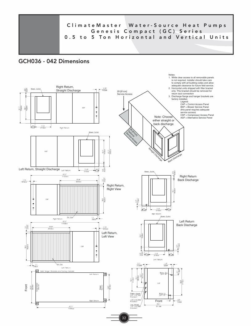
C l i m a t e M a s t e r W a t e r - S o u r c e H e a t P u m p sG e n e s i s C o m p a c t ( G C ) S e r i e s
0 . 5 t o 5 T o n H o r i z o n t a l a n d V e r t i c a l U n i t s
32
GCH036 - 042 Dimensions
Notes:1. While clear access to all removable panels
is not required, installer should take care to comply with all building codes and allow adequate clearance for future fi eld service.
2. Horizontal units shipped with fi lter bracket only. This bracket should be removed for return duct connection
3. Discharge fl ange and hanger brackets are factory installed.
Legend:CAP = Control Access Panel BSP = Blower Service Panel(this panel requires adequate service access)CSP = Compressor Access PanelASP = Alternative Service Panel
Fro
nt
Front
Left ReturnBack Discharge
Left Return, Left View
Right Return, Right View
Left Return, Straight Discharge
Right Return, Straight Discharge
Right ReturnBack Discharge
Note: Choose either straight or back discharge
Straight DischargeBack Discharge
2ft [61cm]
Optional
Service Access
2ft [61cm]Service Access
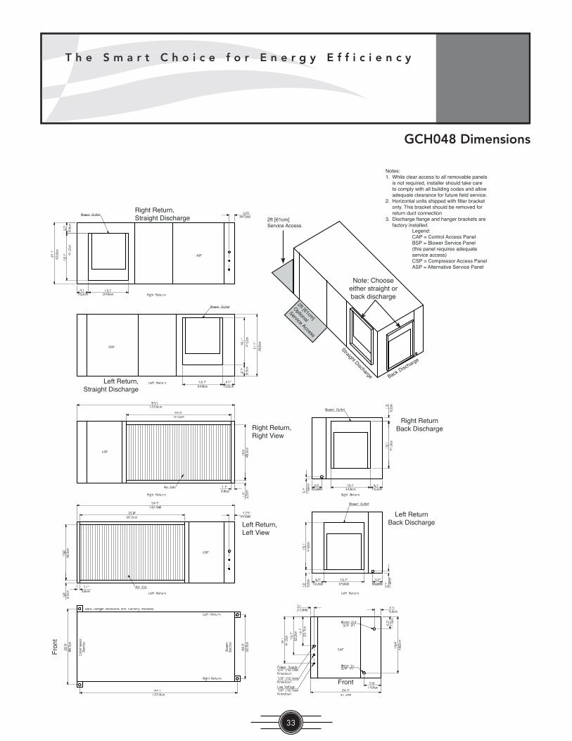
T h e S m a r t C h o i c e f o r E n e r g y E f f i c i e n c y
33
T hh e S m a r t C h o i c e f o r E n e r g
GCH048 Dimensions
Fro
nt
Front
Left ReturnBack DischargeLeft Return,
Left View
Right Return, Right View
Left Return, Straight Discharge
Right Return, Straight Discharge
Right ReturnBack Discharge
Note: Choose either straight or back discharge
Straight Discharge Back Discharge
2ft [61cm]
Optional
Service Access
2ft [61cm]Service Access
Notes:1. While clear access to all removable panels
is not required, installer should take care to comply with all building codes and allow adequate clearance for future fi eld service.
2. Horizontal units shipped with fi lter bracket only. This bracket should be removed for return duct connection
3. Discharge fl ange and hanger brackets are factory installed.
Legend:CAP = Control Access Panel BSP = Blower Service Panel(this panel requires adequate service access)CSP = Compressor Access PanelASP = Alternative Service Panel

C l i m a t e M a s t e r W a t e r - S o u r c e H e a t P u m p sG e n e s i s C o m p a c t ( G C ) S e r i e s
0 . 5 t o 5 T o n H o r i z o n t a l a n d V e r t i c a l U n i t s
34
Notes:1. While clear access to all removable panels
is not required, installer should take care to comply with all building codes and allow adequate clearance for future fi eld service.
2. Horizontal units shipped with fi lter bracket only. This bracket should be removed for return duct connection
3. Discharge fl ange and hanger brackets are factory installed.
Legend:CAP = Control Access Panel BSP = Blower Service Panel(this panel requires adequate service access)CSP = Compressor Access PanelASP = Alternative Service Panel
Fro
nt
Front
Left ReturnBack DischargeLeft Return,
Left View
Right Return, Right View
Left Return, Straight Discharge
Right Return, Straight Discharge
Right ReturnBack Discharge
Note: Choose either straight or back discharge
Straight DischargeBack Discharge
2ft [61cm]
Optional
Service Access
2ft [61cm]Service Access
GCH060 Dimensions
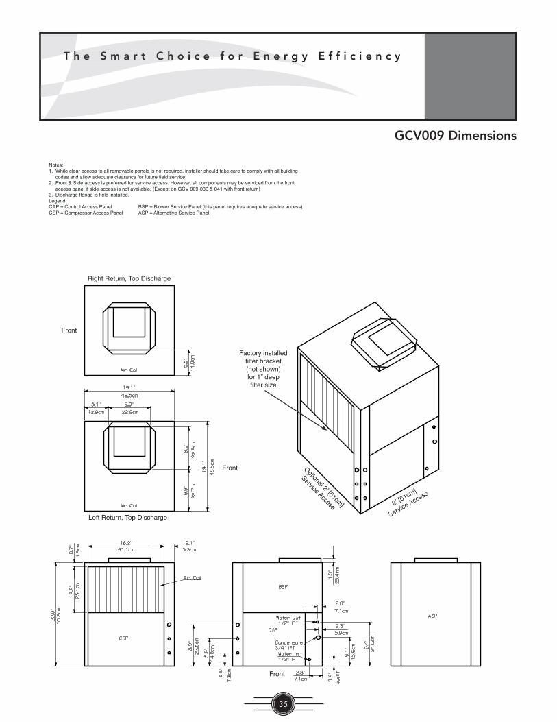
T h e S m a r t C h o i c e f o r E n e r g y E f f i c i e n c y
35
T hh e S m a r t C h o i c e f o r E n e r g
GCV009 Dimensions
Notes:1. While clear access to all removable panels is not required, installer should take care to comply with all building
codes and allow adequate clearance for future fi eld service. 2. Front & Side access is preferred for service access. However, all components may be serviced from the front
access panel if side access is not available. (Except on GCV 009-030 & 041 with front return)3. Discharge fl ange is fi eld installed.Legend:CAP = Control Access Panel BSP = Blower Service Panel (this panel requires adequate service access)CSP = Compressor Access Panel ASP = Alternative Service Panel
Right Return, Top Discharge
Left Return, Top Discharge
Front
Front
Front
Factory installed fi lter bracket (not shown)for 1” deep fi lter size
2’ [61cm]
Service Access
Optional 2’ [61cm]
Service Access

C l i m a t e M a s t e r W a t e r - S o u r c e H e a t P u m p sG e n e s i s C o m p a c t ( G C ) S e r i e s
0 . 5 t o 5 T o n H o r i z o n t a l a n d V e r t i c a l U n i t s
36
GCV018 Dimensions
Notes:1. While clear access to all removable panels is not required, installer should take care to comply with all building
codes and allow adequate clearance for future fi eld service. 2. Front & Side access is preferred for service access. However, all components may be serviced from the front
access panel if side access is not available. (Except on GCV 009-030 & 041 with front return)3. Discharge fl ange is fi eld installed.Legend:CAP = Control Access Panel BSP = Blower Service Panel (this panel requires adequate service access)CSP = Compressor Access Panel ASP = Alternative Service Panel
Right Return, Top Discharge
Left Return, Top Discharge
Front
Front
Front
Factory installed fi lter bracket (not shown)for 1” deep fi lter size
2’ [61cm]
Service Access
Optional 2’ [61cm]
Service Access

T h e S m a r t C h o i c e f o r E n e r g y E f f i c i e n c y
37
T hh e S m a r t C h o i c e f o r E n e r g
GCV024 - 030 Dimensions
Notes:1. While clear access to all removable panels is not required, installer should take care to comply with all building
codes and allow adequate clearance for future fi eld service. 2. Front & Side access is preferred for service access. However, all components may be serviced from the front
access panel if side access is not available. (Except on GCV 009-030 & 041 with front return)3. Discharge fl ange is fi eld installed.Legend:CAP = Control Access Panel BSP = Blower Service Panel (this panel requires adequate service access)CSP = Compressor Access Panel ASP = Alternative Service Panel
Right Return, Top Discharge
Left Return, Top Discharge
Front
Front
Front
Factory installed fi lter bracket (not shown)for 1” deep fi lter size
2’ [61cm]
Service Access
Optional 2’ [61cm]
Service Access

C l i m a t e M a s t e r W a t e r - S o u r c e H e a t P u m p sG e n e s i s C o m p a c t ( G C ) S e r i e s
0 . 5 t o 5 T o n H o r i z o n t a l a n d V e r t i c a l U n i t s
38
GCV036 - 042 Dimensions
Notes:1. While clear access to all removable panels is not required, installer should take care to comply with all building
codes and allow adequate clearance for future fi eld service. 2. Front & Side access is preferred for service access. However, all components may be serviced from the front
access panel if side access is not available. (Except on GCV 009-030 & 041 with front return)3. Discharge fl ange is fi eld installed.Legend:CAP = Control Access Panel BSP = Blower Service Panel (this panel requires adequate service access)CSP = Compressor Access Panel ASP = Alternative Service Panel
Right Return, Top Discharge
Left Return, Top Discharge
Front
Front
Front
Factory installed fi lter bracket (not shown)for 1” deep fi lter size
2’ [61cm]
Service Access
Optional 2’ [61cm]
Service Access

T h e S m a r t C h o i c e f o r E n e r g y E f f i c i e n c y
39
T hh e S m a r t C h o i c e f o r E n e r g
GCV041 Dimensions
Notes:1. While clear access to all removable panels is not required, installer should take care to comply with all building
codes and allow adequate clearance for future fi eld service. 2. Front & Side access is preferred for service access. However, all components may be serviced from the front
access panel if side access is not available. (Except on GCV 009-030 & 041 with front return)3. Discharge fl ange is fi eld installed.Legend:CAP = Control Access Panel BSP = Blower Service Panel (this panel requires adequate service access)CSP = Compressor Access Panel ASP = Alternative Service Panel
Right Return, Top Discharge
Left Return, Top Discharge
Front
Front
Front
Factory installed fi lter bracket (not shown)for 1” deep fi lter size
2’ [61cm]
Service Access
Optional 2’ [61cm]
Service Access

C l i m a t e M a s t e r W a t e r - S o u r c e H e a t P u m p sG e n e s i s C o m p a c t ( G C ) S e r i e s
0 . 5 t o 5 T o n H o r i z o n t a l a n d V e r t i c a l U n i t s
40
GCV048 - 060 Dimensions
Notes:1. While clear access to all removable panels is not required, installer should take care to comply with all building
codes and allow adequate clearance for future fi eld service. 2. Front & Side access is preferred for service access. However, all components may be serviced from the front
access panel if side access is not available. (Except on GCV 009-030 & 041 with front return)3. Discharge fl ange is fi eld installed.Legend:CAP = Control Access Panel BSP = Blower Service Panel (this panel requires adequate service access)CSP = Compressor Access Panel ASP = Alternative Service Panel
Right Return, Top Discharge
Left Return, Top Discharge
Front
Front
Front
Factory installed fi lter bracket (not shown)for 1” deep fi lter size
Air Coil
Air Coil
2’ [61cm]
Service Access
Optional 2’ [61cm]
Service Access

T h e S m a r t C h o i c e f o r E n e r g y E f f i c i e n c y
41
T hh e S m a r t C h o i c e f o r E n e r g
Model Total Left-Front* Right-Front* Left-Back* Right-Back*
GCH006Lbs 103 37 24 23 19
kg 46.72 16.78 10.89 10.43 8.62
GCH009Lbs 105 38 24 23 20
kg 47.63 17.24 10.89 10.43 9.07
GCH012Lbs 114 42 26 25 21
kg 51.71 19.05 11.79 11.34 9.53
GCH018Lbs 181 66 42 40 33
kg 82.10 29.94 19.05 18.14 14.97
GCH024Lbs 189 70 43 42 34
kg 85.73 31.75 19.50 19.05 15.42
GCH030Lbs 197 74 45 43 35
kg 89.36 33.57 20.41 19.50 15.88
GCH036Lbs 203 75 47 44 37
kg 92.08 34.02 21.32 19.96 16.78
GCH042Lbs 218 81 50 48 39
kg 98.88 36.74 22.68 21.77 17.69
GCH048Lbs 263 98 60 58 47
kg 119.29 44.45 27.22 26.31 21.32
GCH060Lbs 303 103 64 61 75
kg 137.44 46.72 29.03 27.67 34.02
*Front is control box end.
Corner Weights for GCH Series Units
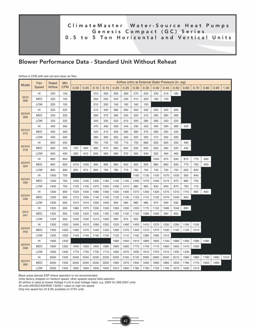
C l i m a t e M a s t e r W a t e r - S o u r c e H e a t P u m p sG e n e s i s C o m p a c t ( G C ) S e r i e s
0 . 5 t o 5 T o n H o r i z o n t a l a n d V e r t i c a l U n i t s
42
Blower Performance Data - Standard Unit Without Reheat
ModelFan
SpeedRatedAirfl ow
MinCFM
Airfl ow (cfm) at External Static Pressure (in. wg)
0.00 0.05 0.10 0.15 0.20 0.25 0.30 0.35 0.40 0.45 0.50 0.60 0.70 0.80 0.90 1.00
GCH006
HI 220 150 310 300 290 280 270 250 230 210 180
MED 220 150 260 250 240 230 210 200 190 150
LOW 220 150 210 200 190 180 160 150
GCH/V009
HI 325 225 410 400 380 360 350 330 320 300 280
MED 325 225 390 370 360 340 320 310 290 280 260
LOW 325 225 340 330 322 310 300 280 260 250 220
GCH/V012
HI 400 300 470 460 450 440 430 420 400 390 380 320
MED 400 300 420 410 400 390 380 370 360 350 340
LOW 400 300 360 360 350 340 320 320 310 300 290
GCH/V018
HI 600 450 760 740 720 710 700 680 650 600 550 460
MED 600 450 700 690 680 670 660 650 630 620 600 560 520 430
LOW 600 450 620 610 600 590 580 570 560 540 520 490 460
GCH/V024
HI 800 600 1000 970 930 870 770 690
MED 800 600 1010 1000 990 980 960 940 920 900 880 860 830 770 700 600
LOW 800 600 820 810 800 790 780 770 760 750 730 720 700 650 600
GCH/V030
HI 1000 750 1160 1130 1100 1070 1030 950 840
MED 1000 750 1250 1230 1200 1180 1150 1120 1090 1070 1040 1010 970 890 750
LOW 1000 750 1120 1100 1070 1050 1030 1010 980 960 930 900 870 790 710
GCH/V036
HI 1200 900 1520 1500 1480 1460 1430 1400 1370 1350 1320 1270 1210 1110 960 840
MED 1200 900 1210 1200 1140 1140 1130 1130 1120 1110 1100 1070 1040 940
LOW 1200 900 1010 1010 1000 1000 990 990 980 980 970 950 930
GCV041
HI 1325 950 1380 1370 1350 1330 1300 1260 1220 1170 1120 1080 1040 890
MED 1325 950 1230 1220 1200 1190 1180 1150 1120 1080 1030 990 950
LOW 1325 950 1040 1030 1010 1000 990 970 950
GCH/V042
HI 1350 1050 1640 1610 1580 1550 1520 1490 1450 1410 1370 1330 1290 1190 1100
MED 1350 1050 1490 1470 1440 1420 1390 1370 1340 1310 1270 1230 1190 1120 1010
LOW 1350 1050 1140 1140 1130 1130 1120 1110 1100 1080 1060 1010
GCH/V048
HI 1600 1200 1980 1950 1910 1860 1800 1740 1680 1490 1280 1280
MED 1600 1200 1940 1920 1900 1880 1860 1820 1770 1740 1710 1660 1600 1410 1000
LOW 1600 1200 1770 1750 1730 1710 1690 1670 1650 1610 1570 1510 1450 1330
GCH/V060
HI 2000 1500 2240 2240 2230 2220 2200 2160 2120 2090 2060 2040 2010 1960 1880 1790 1660 1510
MED 2000 1500 2050 2050 2040 2020 1990 1970 1940 1920 1890 1860 1830 1780 1710 1620 1490
LOW 2000 1500 1850 1850 1840 1830 1810 1800 1780 1760 1730 1700 1670 1600 1510
Black areas denote ESP where operation is not recommendedUnits factory shipped on medium speed, other speeds require fi eld selectionAll airfl ow is rated at lowest Voltage if unit is dual Voltage rated, e.g. 208V for 208-230V unitsAll units ARI/ISO/ASHRAE 13256-1 rated on high fan speedOnly two speed fan (H & M) available on 575V units
Airfl ow in CFM with wet coil and clean air fi lter.

T h e S m a r t C h o i c e f o r E n e r g y E f f i c i e n c y
43
T hh e S m a r t C h o i c e f o r E n e r g
ModelFan
SpeedRatedAirfl ow
MinCFM
Airfl ow (cfm) at External Static Pressure (in. wg)
0.00 0.05 0.10 0.15 0.20 0.25 0.30 0.35 0.40 0.45 0.50 0.60 0.70 0.80 0.90 1.00
GCH/V018
HS HI 600 450 790 780 770 760 750 730 710 690 650 530 430
HS MED 600 450 750 740 720 710 700 690 670 670 660 650 630 600 490 390
HS LOW 600 450 670 660 640 630 620 610 600 590 580 580 570 530 420
GCH/V024
HS HI 800 600 1030 950 840 700
HS MED 800 600 1040 1010 970 890 750 620
HS LOW 800 600 1030 1010 980 960 930 900 870 790 710
GCH/V030
HS HI 1000 750 1160 1040 920 800 750
HS MED 1000 750 1130 1080 1030 930 820 750
HS LOW 1000 750 1050 1040 1030 1010 990 980 960 940 910 880 840 750
GCH/V036
HS HI 1200 900 1530 1500 1470 1400 1290 1170 960
HS MED 1200 900 1360 1350 1340 1330 1320 1310 1300 1280 1260 1250 1230 1150 1070 910
HS LOW 1200 900 1030 1020 1010 1010 1000 1000 990 980 960 950 930
GCH/V042
HS HI 1350 1050 1550 1540 1520 1500 1470 1460 1450 1380 1240 1080
HS MED 1350 1050 1390 1380 1370 1360 1350 1340 1320 1310 1300 1280 1250 1180 1080
HS LOW 1350 1050
GCH/V048
HS HI 1600 1200 2060 2040 2010 1960 1880 1790 1660 1510
HS MED 1600 1200 2050 2050 2040 2020 1990 1970 1940 1920 1890 1860 1830 1780 1710 1620 1490 1320
HS LOW 1600 1200 1850 1850 1840 1830 1810 1800 1780 1760 1730 1700 1670 1600 1510 1380 1220
GCH/V060
HS HI 2000 1500 2400 2400 2390 2380 2370 2360 2340 2320 2300 2270 2240 2200 2130 2060 1980 1890
HS MED 2000 1500 2160 2160 2150 2150 2140 2110 2080 2060 2040 2030 2020 1980 1930 1880 1490 1750
HS LOW 2000 1500 1930 1930 1920 1920 1910 1900 1890 1890 1880 1870 1850 1830 1800 1750 1700 1620
Black areas denote ESP where operation is not recommendedUnits factory shipped on medium speed, other speeds require fi eld selectionAll airfl ow is rated at lowest Voltage if unit is dual Voltage rated, e.g. 208V for 208-230V unitsAll units ARI/ISO/ASHRAE 13256-1 rated on high fan speedOnly two speed fan (H & M) available on 575V units
Airfl ow in CFM with wet coil and clean air fi lter.
Blower Performance Data - Standard Unit Without Reheat - Hi Static

C l i m a t e M a s t e r W a t e r - S o u r c e H e a t P u m p sG e n e s i s C o m p a c t ( G C ) S e r i e s
0 . 5 t o 5 T o n H o r i z o n t a l a n d V e r t i c a l U n i t s
44
GCV Unit Blower Performance with ClimaDry Reheat Option
GCV Unit Blower Performance with ClimaDry Reheat Option
GCV Unit Blower Performance with Wet Coil
Example:Reheat coil loss can be determined from the above table. Coil velocity (FPM) = Airfl ow (CFM) / Face Area (sq. ft.)
1) GCV036 has a face area of 3.63 sq. ft. (see physical data table).2) At 1,100 cfm, coil velocity (FPM) = 1,100 / 3.63 = 303 FPM3) From above table, it will be necessary to subtract 0.068 from the blower performance ESP.4) On medium speed, the GCV036 (without reheat – see blower table) can deliver 1,100 CFM at 0.40 in. wg.;
with the reheat coil, it now delivers 1,063 CFM at 0.40 in. wg (includes adder for wet coil) or 1,100 CFM at 0.33 in. wg.
5) To compensate, high speed fan should be used to overcome pressure drop of reheat coil.
Example:Wet coil loss can be determined from the above table. Coil velocity (FPM) = Airfl ow (CFM) / Face Area (sq. ft.)
1) GCV036 has a face area of 3.63 sq. ft. (see physical data table).2) At 1,100 cfm, coil velocity (FPM) = 1,100 / 3.63 = 303 FPM3) From above table, it will be necessary to subtract 0.080 from the blower performance ESP.4) On medium speed, the GCV036 (without dry coil – see blower table) can deliver 1,100 CFM at 0.40 in. wg.;
with a wet coil, it now delivers 1,055 CFM at 0.40 in. wg or 1,100 CFM at 0.32 in. wg.5) If unit has reheat option, reheat coil pressure drop already includes adjustment for wet coil (Reheat ESP
Loss Table).
Coil FaceVelocity
FPM
GCV with Reheat ESP Loss
GCV018, 024, 030In. of Water
GCV036, 042
In. of Water
GCV048, 060
In. of Water
200 0.060 0.049 0.038
250 0.070 0.055 0.040
300 0.090 0.068 0.045
350 0.124 0.091 0.059
400 0.164 0.129 0.094
450 0.252 0.221 0.189
500 0.380 0.350 0.320
For GCV units with Reheat coil applications. calculate coil face velocity of theentering air. From the table above fi nd ESP loss for Reheat application. This loss includes the wet coil loss.
Coil FaceVelocity
FPM
Wet Coil Reduction
In. of Water
200 0.030
250 0.055
300 0.080
350 0.100
400 0.120
450 0.140
500 0.160

T h e S m a r t C h o i c e f o r E n e r g y E f f i c i e n c y
45
T hh e S m a r t C h o i c e f o r E n e r g
Unit Electrical DataStandard GC Units
All GC Units Standard GC Unit GCV Units with Reheat
ModelVoltageCode
VoltageMin/MaxVoltage
Compressor FanMotorFLA
TotalUnitFLA
MinCircuitAmps
MaxFuse/HACR
ReheatPumpFLA
TotalUnitFLA
MinCircuitAmps
MaxFuse/HACRQTY RLA LRA
GCH006
G 208-230/60/1 197/254 1 2.9 17.7 0.4 3.3 4.1 15 N/A N/A N/A N/A
E 265/60/1 239/292 1 2.5 15.0 0.4 2.8 3.5 15 N/A N/A N/A N/A
GCH/V009
G 208-230/60/1 197/254 1 3.9 22.2 0.8 4.7 5.7 15 N/A N/A N/A N/A
E 265/60/1 239/292 1 3.3 18.8 0.7 4.0 4.8 15 N/A N/A N/A N/A
GCH/V012
G 208-230/60/1 197/254 1 5.3 27.9 0.8 6.1 7.5 15 N/A N/A N/A N/A
E 265/60/1 239/292 1 4.2 22.2 0.7 4.9 6.0 15 N/A N/A N/A N/A
GCH/V018
G 208-230/60/1 197/254 1 8.6 49.0 1.0 9.6 11.7 20 0.80 10.4 12.5 20
E 265/60/1 239/292 1 8.1 44.0 0.9 8.9 11.0 15 0.70 9.6 11.7 15
GCH/V024
G 208-230/60/1 197/254 1 9.8 56.0 1.5 11.3 13.8 20 0.80 12.1 14.6 20
E 265/60/1 239/292 1 9.1 55.0 1.3 10.4 12.7 20 0.70 11.1 13.4 20
H 208-230/60/3 197/254 1 6.7 51.0 1.5 8.2 9.9 15 0.80 9.0 10.7 15
F* 460/60/3 414/506 1 3.5 25.0 0.8 4.2 5.1 15 0.70 4.9 5.8 15
GCH/V030
G 208-230/60/1 197/254 1 11.2 61.0 3.0 14.2 16.9 25 0.80 15.0 17.7 25
E 265/60/1 239/292 1 10.0 58.0 2.7 12.7 15.2 25 0.70 13.4 15.9 25
H 208-230/60/3 197/254 1 6.9 55.0 3.0 9.9 11.7 15 0.80 10.7 12.5 15
F* 460/60/3 414/506 1 3.6 28.0 1.7 5.3 6.2 15 0.70 6.0 6.9 15
GCH/V036
G 208-230/60/1 197/254 1 15.4 82.0 1.8 17.2 21.1 35 0.80 18.0 21.9 35
E 265/60/1 239/292 1 14.4 83.0 2.0 16.4 20.0 30 0.70 17.1 20.7 35
H 208-230/60/3 197/254 1 9.6 70.0 1.8 11.4 13.8 20 0.80 12.2 14.6 20
F* 460/60/3 414/506 1 4.9 33.0 1.2 6.1 7.4 15 0.70 6.8 8.1 15
GCV041
G 208-230/60/1 197/254 1 16.2 96.0 3.0 19.2 23.2 35 N/A N/A N/A N/A
H 208-230/60/3 197/254 1 10.3 75.0 3.0 13.3 15.8 25 N/A N/A N/A N/A
F* 460/60/3 414/506 1 4.3 40.0 1.7 6.0 7.1 15 N/A N/A N/A N/A
N 575/60/3 518/633 1 3.7 31.0 1.5 5.2 6.1 15 N/A N/A N/A N/A
GCH/V042
G 208-230/60/1 197/254 1 17.1 105.0 3.0 20.1 24.3 40 0.80 20.9 25.1 40
H 208-230/60/3 197/254 1 10.7 85.0 3.0 13.7 16.4 25 0.80 14.5 17.2 25
F* 460/60/3 414/506 1 5.3 42.0 1.7 7.0 8.3 15 0.70 7.7 9.0 15
N 575/60/3 518/633 1 4.3 34.0 1.4 5.7 6.8 15 N/A N/A N/A N/A
GCH/V048
G 208-230/60/1 197/254 1 18.3 102.0 3.4 21.7 26.3 40 1.07 22.7 27.3 45
H 208-230/60/3 197/254 1 12.6 91.0 3.4 16.0 19.2 30 1.07 17.1 20.3 30
F* 460/60/3 414/506 1 5.7 42.0 1.8 7.5 8.9 15 1.00 8.5 9.9 15
N 575/60/3 518/633 1 4.7 39.0 1.4 6.1 7.2 15 N/A N/A N/A N/A
GCH/V060
G 208-230/60/1 197/254 1 25.6 170.0 4.9 29.9 36.4 60 1.07 31.0 37.4 60
H 208-230/60/3 197/254 1 14.7 124.0 4.9 19.0 22.7 35 1.07 20.1 23.8 35
F* 460/60/3 414/506 1 7.4 59.6 2.5 9.9 11.8 15 1.00 10.9 12.8 20
N 575/60/3 518/633 1 5.9 49.4 1.9 7.8 9.3 15 N/A N/A N/A N/A
HACR circuit breaker in USA onlyAll fuses Class RK-5* All F voltage (460V) units with ClimaDry Reheat require a four (4) wire power supply with neutral; reheat pump is rated 265V and is wired between one hot leg and neutral
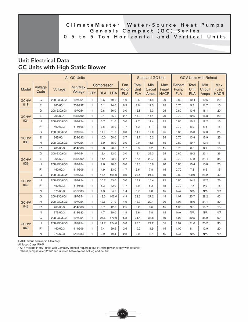
C l i m a t e M a s t e r W a t e r - S o u r c e H e a t P u m p sG e n e s i s C o m p a c t ( G C ) S e r i e s
0 . 5 t o 5 T o n H o r i z o n t a l a n d V e r t i c a l U n i t s
46
All GC Units Standard GC Unit GCV Units with Reheat
ModelVoltageCode
VoltageMin/MaxVoltage
Compressor FanMotorFLA
TotalUnitFLA
MinCircuitAmps
MaxFuse/HACR
ReheatPumpFLA
TotalUnitFLA
MinCircuitAmps
MaxFuse/HACRQTY RLA LRA
GCH/V018
G 208-230/60/1 197/254 1 8.6 49.0 1.0 9.6 11.8 20 0.80 10.4 12.6 20
E 265/60/1 239/292 1 8.1 44.0 0.9 9.0 11.0 15 0.70 9.7 11.7 15
GCH/V024
G 208-230/60/1 197/254 1 9.8 56.0 3.0 12.8 15.3 25 0.80 13.6 16.1 20
E 265/60/1 239/292 1 9.1 55.0 2.7 11.8 14.1 20 0.70 12.5 14.8 20
H 208-230/60/3 197/254 1 6.7 51.0 3.0 9.7 11.4 15 0.80 10.5 12.2 15
F* 460/60/3 414/506 1 3.5 25.0 1.7 5.2 6.1 15 0.70 5.9 6.8 15
GCH/V030
G 208-230/60/1 197/254 1 11.2 61.0 3.0 14.2 17.0 25 0.80 15.0 17.8 25
E 265/60/1 239/292 1 10.0 58.0 2.7 12.7 15.2 25 0.70 13.4 15.9 25
H 208-230/60/3 197/254 1 6.9 55.0 3.0 9.9 11.6 15 0.80 10.7 12.4 15
F* 460/60/3 414/506 1 3.6 28.0 1.7 5.3 6.2 15 0.70 6.0 6.9 15
GCH/V036
G 208-230/60/1 197/254 1 15.4 82.0 3.0 18.4 22.3 35 0.80 19.2 23.1 35
E 265/60/1 239/292 1 14.4 83.0 2.7 17.1 20.7 35 0.70 17.8 21.4 35
H 208-230/60/3 197/254 1 9.6 70.0 3.0 12.6 15.0 20 0.80 13.4 15.8 20
F* 460/60/3 414/506 1 4.9 33.0 1.7 6.6 7.8 15 0.70 7.3 8.5 15
GCH/V042
G 208-230/60/1 197/254 1 17.1 105.0 3.0 20.1 24.4 40 0.80 20.9 25.2 40
H 208-230/60/3 197/254 1 10.7 85.0 3.0 13.7 16.4 25 0.80 14.5 17.2 25
F* 460/60/3 414/506 1 5.3 42.0 1.7 7.0 8.3 15 0.70 7.7 9.0 15
N 575/60/3 518/633 1 4.3 34.0 1.4 5.7 6.8 15 N/A N/A N/A N/A
GCH/V048
G 208-230/60/1 197/254 1 18.3 102.0 4.9 22.6 27.2 45 1.07 23.7 28.2 45
H 208-230/60/3 197/254 1 12.6 91.0 4.9 16.9 20.1 30 1.07 18.0 21.1 30
F* 460/60/3 414/506 1 5.7 42.0 2.5 8.2 9.6 15 1.00 9.3 10.7 15
N 575/60/3 518/633 1 4.7 39.0 1.9 6.6 7.8 15 N/A N/A N/A N/A
GCH/V060
G 208-230/60/1 197/254 1 25.6 170.0 5.8 31.4 37.8 60 1.07 32.5 38.9 60
H 208-230/60/3 197/254 1 14.7 124.0 5.8 20.5 24.2 35 1.07 21.6 25.2 35
F* 460/60/3 414/506 1 7.4 59.6 2.6 10.0 11.9 15 1.00 11.1 12.9 20
N 575/60/3 518/633 1 5.9 49.4 2.3 8.0 9.7 15 N/A N/A N/A N/A
HACR circuit breaker in USA onlyAll fuses Class RK-5* All F voltage (460V) units with ClimaDry Reheat require a four (4) wire power supply with neutral; reheat pump is rated 265V and is wired between one hot leg and neutral
Unit Electrical DataGC Units with High Static Blower

T h e S m a r t C h o i c e f o r E n e r g y E f f i c i e n c y
47
T hh e S m a r t C h o i c e f o r E n e r g
Unit Wiring Diagram Matrix
Only CXM and DXM diagrams, with a representative diagram of LON and MPC Options are pre sented in this submittal. Other diagrams can be lo cated online at www.climatemaster.com using the part num bers presented below.
Model RefrigerantWiring Diagram
Part NumberElectrical Control DDC Agency
GC SeriesSinglePhase
R22 96B0006N01
208-230/60/1,265/60/1,
220-240/50/1
CXM
- -
R22 & R407C 96B0006N06 - CE
R22 96B0006N03 LON -
R22 96B0006N09 MPC -
R22 & R407C 96B0006N11 MPC CE
R22 96B0006N02
DXM
- -
R22 & R407C 96B0006N05 - CE
R22 96B0006N04 LON -
R22 96B0006N10 MPC -
R22 96B0014N02 DXM with Reheat Option
GC SeriesThreePhase
(230 Style)
R22 96B0007N01
208-230/60/3,220-240/50/3
CXM
- -
R22 96B0007N03 LON -
R22 96B0007N06 MPC -
R22 96B0007N02
DXM
- -
R22 96B0007N04 LON -
R22 96B0007N07 MPC -
GC SeriesThreePhase
(460 Style)
R22 96B0008N01
460/60/3,575/60/3,
380-420/50/3
CXM
-
R22 & R407C 96B0008N06 - CE
R22 96B0008N03 LON -
R22 96B0008N08 MPC -
R22 96B0008N02
DXM
- -
R22 & R407C 96B0008N05 - CE
R22 96B0008N04 LON -
R22 96B0008N09 MPC -
All wiring diagrams available at www.climatemaster.com. R407C submittals will only contain CE Mark wiring diagrams

C l i m a t e M a s t e r W a t e r - S o u r c e H e a t P u m p sG e n e s i s C o m p a c t ( G C ) S e r i e s
0 . 5 t o 5 T o n H o r i z o n t a l a n d V e r t i c a l U n i t s
48
Typical Wiring Diagram - CXM Controls - Single Phase

T h e S m a r t C h o i c e f o r E n e r g y E f f i c i e n c y
49
T hh e S m a r t C h o i c e f o r E n e r g
Typical Wiring Diagram - DXM Controls - Single Phase

C l i m a t e M a s t e r W a t e r - S o u r c e H e a t P u m p sG e n e s i s C o m p a c t ( G C ) S e r i e s
0 . 5 t o 5 T o n H o r i z o n t a l a n d V e r t i c a l U n i t s
50
CXM AND DXM SERIES CONTROLLERSThe CXM and DXM Series Controllers are designed to enhance Water-Source Heat Pump unit performance with the ability to coordinate complete systems. CXM Series controllers offer complete stand-alone unit control. DXM Series controls add advanced unit operation and system control features. Either control can allow you to connect your heat pump system to a LonWorks or MPC (Multiple ProtoCol -- BACNET, N2, Modbus) DDC control system which includes lighting and other energy saving controls. The CXM and DXM Series are the most advanced controllers made by any heat pump man u fac tur er today.
STANDARD CXM CONTROL FUNCTIONS The CXM controller package offers all of the basic features available with elec tro me chan i cal systems, plus 15 additional standard functions. This group of added features includes condensate overfl ow, anti-short cycle, random start, aircoil low temperature limit (except GC Series and water-to-water units), under/over voltage protection, and intelligent reset, designed to automatically restart a unit within a specifi c period of time following a fault, given the fault has been adequately corrected. Also included are LED fault and status indication to aid in diagnostics and troubleshooting. These added features, and the many others provided, are specifi cally designed to improve the life expectancy, reliability, and serviceability of Water-Source Heat Pumps. The CXM is compatible with most heat pump thermostats.
ADDITIONAL DXM CONTROL FUNCTIONSThe DXM controller adds system functions such as emergency shutdown and night setback with override to the stand-alone capability provided by the CXM. Fully confi gured, the DXM offers 17 additional features over the CXM, including advanced system control capabilities such as intelligent fan speed, reheat control, two-stage compressor, and boilerless electronic heat. The DXM is compatible with almost any type of thermostat, whether heat pump or heat/cool.
UNIT/SYSTEM OPERATING EFFICIENCYEmergency shutdown, night setback, pump restart and advanced unit functional control all work to enhance the performance of your system. These features are stan dard on DXM Series Electronic Controllers.
COMFORT CONTROLUser se lect able or in tel li gent control of fan speed, de hu mid i fi ca tion modes, out door air damper control, and a com plete of fer ing of ac cu rate electronic thermostats add up to in creased comfort through superior unit control.
DIAGNOSTICSClimateMaster controls provide on-board diagnostics which highlight eight (seven for GC Series) different reasons for unit malfunction, speeding up service time, elim i nat ing un nec es sary service charges, and minimizing down time. The exclusive UPS (Unit Performance Sentinel) provides an early warning of ineffi cient operating conditions before unit shutdown actually occurs. Fault types are not only indicated at the control, but are kept in memory after a user reset for future service use. And another ClimateMaster exclusive, fault types can be displayed on a conventional thermostat if equipped with a fault LED, or can be remotely communicated with the DDC option.
CXM Control Board
DXM Control Board

T h e S m a r t C h o i c e f o r E n e r g y E f f i c i e n c y
51
T hh e S m a r t C h o i c e f o r E n e r g
OPEN-PROTOCOL DDC CAPABILITYThe CXM and DXM Series can be upgraded with the ad di tion of a separate LonMark or MPC (Multiple ProtoCol -- BACNET, N2, Modbus) DDC module, ei ther as a factory option, or fi eld installed at a later date.
LonWorks is an open protocol DDC network, which can be in te grat ed with most third-par ty building automation systems. In addition, the MPC controller offers the other popular building management system protocols (BACNET, N2, Modbus). ClimateMaster's DDC options pro vide the fl exibility to upgrade your control system as your de mands require, and gives you the freedom to interface with most any DDC sys tem vendor. Leaving air and water tem per a ture sensors are factory mounted, for remote mon i tor ing, and a wide range of wall sen sors are avail able. The wall sensors utilize a simple interface and can provide dig i tal display and the unit control ca pa bil i ty found in conventional thermostats.
ASW Wall Sensors for Lon or MPC DDC Systems

C l i m a t e M a s t e r W a t e r - S o u r c e H e a t P u m p sG e n e s i s C o m p a c t ( G C ) S e r i e s
0 . 5 t o 5 T o n H o r i z o n t a l a n d V e r t i c a l U n i t s
52
Basic Features CXM CXM-Lon CXM-MPC DXM DXM-Lon DXM-MPC
High and Low Refrigerant Pressure Protection S S S S S S
Water Coil Low Temperature Limit S S S S S S
True 24VA Thermostat Signals S S S S S S
Thermostat Inputs Compatible with Triacs S S S S S S
Condensate Overfl ow Sensor S S S S S S
Anti-Short-Cyle Time Delay S S S S S S
Random Start S S S S S S
Alarm (selectable dry contact or 24VA) S S S S S S
Water Valve Relay S S S S S S
Water Valve Relay with Compressor Delay N/A N/A N/A S S S
Emergency Shutdown N/A DDC DDC S DDC DDC
Night Setback with Override N/A DDC DDC S DDC DDC
Outdoor Air Damper Control N/A N/A N/A S S S
Advanced Features
Intelligent Reset S S S S S S
High and Low Voltage Protection S S S S S S
Air Coil Low Temperature Limit S S S S S S
Antifreeze Setpoint Field Select (water, antifreeze) S S S S S S
Electric Heat Control Outputs S S S S S S
Boilerless Electric Heat Control N/A N/A N/A S S S
Intelligent Reversing Valve Operation N/A DDC DDC S S S
High/Low Fan Speed Outputs N/A N/A N/A S S S
Intelligent Fan Speed Control N/A N/A N/A S S S
Thermostat Type Select (Y,O or Y,W) N/A N/A N/A S N/A N/A
Reversing Valve Signal Select (O or B) N/A N/A N/A S N/A N/A
Dehumidistat Input N/A N/A N/A S S S
Reheat Dehumidifi cation Control* N/A N/A N/A O O O
Multiple Units on One Thermostat/Wall Sensor N/A DDC DDC S DDC DDC
Service and Reliability Features
Service Test Mode S S S S S S
LED Fault and Status Lights S S S S S S
Fault Memory after Reset S S S S S S
Unit Performance Sentinel S S S S S S
Harness-Type Factory Wiring Connections S S S S S S
Fully Noise-Tested Design S S S S S S
CE Approval S S S S S S
Removable Low Voltage Connector N/A N/A N/A S S S
DDC / Energy Management Features
Echelon LonMark Compliant N/A S N/A N/A S N/A
BACNET Compliant N/A N/A S N/A N/A S
Johnson N2 Compliant N/A N/A S N/A N/A S
Modbus Compliant N/A N/A S N/A N/A S
Leaving Air and Water Temperature Sensor N/A S S N/A S S
Digital Wall Sensor N/A O O N/A O O
S = Standard O = Optional DDC = Feature can be provided by DDC System CXM-Lon = CXM with LonMark Module
DXM-Lon = DXM with LonMark Module CXM-MPC = CXM with MPC Module DXM-MPC = DXM with MPC Module
* = Check with your Factory Representative for model availability MPC = Multiple ProtoCol (BACNET, N2, Modbus)

T h e S m a r t C h o i c e f o r E n e r g y E f f i c i e n c y
53
T hh e S m a r t C h o i c e f o r E n e r g
GC Compact Series 60Hz Engineering Guide Specs. Rev.: 07/05/06General:Furnish and install ClimateMaster “Genesis” Water Source Heat Pumps, as indicated on the plans. Equipment shall be completely assembled, piped and internally wired. Capacities and characteristics as listed in the schedule and the specifi cations that follow.
Horizontal / Vertical Water Source Heat Pumps:Units shall be supplied completely factory built for an entering water temperature range from 60° to 95°F (15.6° to 35.0°C) as standard. Equivalent units from other manufacturers can be proposed provided approval to bid is given 10 days prior to bid closing. All equipment listed in this section must be rated and certifi ed in accordance with American Refrigeration Institute / International Standards Organization (ARI / ISO) and Canadian Standards Association (CSA-US). The units shall have ARI / ISO and CSA-US labels. All units shall be fully quality tested by factory run testing under normal operating conditions as described herein. Quality control system shall automatically perform via computer: triple leak check, pressure tests, evacuate and accurately charge system, perform detailed heating and cooling mode tests, and quality cross check all operational and test conditions to pass/fail criteria. Units tested without water fl ow are not acceptable.
Basic Construction: Horizontal Units shall have one of the following air fl ow arrangements: Left Inlet/Straight (Right) Discharge; Right Inlet/Straight (Left) Discharge; Left Inlet/Back Discharge; or Right Inlet/Back Discharge as shown on the plans. Units must have the ability to be fi eld convertible from straight to back or back to straight discharge with no additional parts or unit structure modifi cation. Horizontal units will have factory installed hanger brackets with rubber isolation grommets packaged separately.
Vertical Units shall have one of the following air fl ow arrangements: Left Return/Top Discharge, Right Return/Top Discharge, as shown on the plans.
If units with these arrangements are not used, the contractor is responsible for any extra costs incurred by other trades. All units (horizontal and vertical) must have a minimum of three access panels for serviceability of compressor compartment. Units having only one access panel to compressor/heat exchangers/expansion device/refrigerant piping shall not be acceptable.
The heat pumps shall be fabricated from heavy gauge galvanized steel. All interior surfaces shall be lined with 1/2 inch (12.7mm) thick, dual density, 1-3/4 lb/ft3 (28 kg/m3) acoustic type glass fi ber insulation. Insulation placement shall be designed in a manner that will eliminate any exposed edges to prevent the introduction of glass fi bers into the air stream.
Vertical heat pumps shall be fabricated from heavy gauge galvanized steel with powder coat paint fi nish. The color will be Polar Ice. Both sides of the steel shall be painted for added protection.
Standard cabinet panel insulation must meet NFPA 90A requirements, air erosion and mold growth limits of UL-181, stringent fungal resistance test per ASTM-C1071 and ASTM G21, and shall meet zero level bacteria growth per ASTM G22. Unit insulation must meet these stringent requirements or unit(s) will not be accepted.
All horizontal units to have factory installed 1” (25.4mm) discharge air duct collars, 1” (25.4mm) fi lter rails with 1” (25.4mm) fi lters factory installed, and factory installed unit-mounting brackets. Vertical units to have fi eld installed discharge air duct collar, shipped loose and 1” (25.4mm) fi lter rails with 1” (25.4mm) fi lters factory installed. If units with these factory installed provisions are not used, the contractor is responsible for any extra costs to fi eld install these provisions, and/or the extra costs for his sub-contractor to install these provisions.
All units must have an insulated panel separating the fan compartment from the compressor compartment. Units with the compressor in the air stream are not acceptable. Units shall have a factory installed 1 inch (25.4mm) wide fi lter bracket for fi lter removal from either side. Units shall have a 1 inch (25.4mm) thick throwaway type glass fi ber fi lter. The contractor shall purchase one spare set of fi lters and replace factory shipped fi lters on completion of start-up. Filters shall be standard sizes. If units utilize non-standard fi lter sizes then the contractor shall provide 12 spare fi lters for each unit.
Cabinets shall have separate holes and knockouts for entrance of line voltage and low voltage control wiring. All factory-
C l i m a t e M a s t e r W a t e r - S o u r c e H e a t P u m p sG e n e s i s C o m p a c t ( G C ) S e r i e s
0 . 5 t o 5 T o n H o r i z o n t a l a n d V e r t i c a l U n i t s
54
installed wiring passing through factory knockouts and openings shall be protected from sheet metal edges at openings by plastic ferrules. Supply and return water connections shall be copper IPT fi ttings. All water connections and electrical knockouts must be in the compressor compartment corner post so as not to interfere with the serviceability of unit. Contractor shall be responsible for any extra costs involved in the installation of units that do not have this feature. Contractor must ensure that units can be easily removed for servicing and coordinate locations of electrical conduit and lights with the electrical contractor.
Option: Contractor shall install 2-inch (50.8mm) fi lter brackets and 2 inch(50.8mm) glass fi ber throwaway fi lters on all units.
Option: Ultra Quiet package shall consist of dual density acoustical, 1/2”(12.7mm) fi berglass insulation; spring isolation under compressor; discharge muffl er (except rotary compressors); and sound attenuating material applied to the fan housing.
Option: The refrigerant to air heat exchanger shall be “electro-coated” with a low cure cathodic epoxy material a minimum of 0.4 mils thick (0.4 – 1.5 mils range) on all surfaces. The black colored coating shall provide a minimum of 1000 hours salt spray protection per ASTM B117-97 on all galvanized end plates and copper tubing, and a minimum of 2000 hours of salt spray on all aluminum fi ns. The material shall be formulated without the inclusion of any heavy metals and shall exhibit a pencil hardness of 2H (ASTM D3363-92A), crosshatch adhesion of 4B-5B (ASTM D3359-95), and impact resistance of 160 in/lbs direct (ASTM D2794-93).
Option (vertical units only): Unit shall include ClimaDry reheat option. Only modulating reheat that will adjust capacity based upon supply air temperature to provide “neutral” (72ºF, 22.2ºC) constant air temperature will be accepted. “Neutral” supply air temperature shall be provided regardless of entering loop water temperatures (above 55ºF, 12.8ºC) or refrigerant condensing pressures. Control of reheat must be accomplished via a humidistat or dehumidistat contact closure. Refrigerant circuit must be ARI certifi ed. Refrigerant circuits that are not ARI certifi ed when the reheat option is applied will not be accepted.
Fan and Motor Assembly:Blower shall have inlet rings to allow removal of wheel and motor from one side without removing housing. Units shall have a direct-drive centrifugal fan. The fan motor shall be 3-speed (2-speed for 575V), permanently lubricated, PSC type, with internal thermal overload protection. Units supplied without permanently lubricated motors must provide external oilers for easy service. The fan motor on small and medium size units (006-042) shall be isolated from the fan housing by a torsionally fl exible motor mounting system with rubber type grommets to inhibit vibration induced high noise levels associated with “hard wire belly band” motor mounting. The fan motor on larger units (048 & 060) shall be isolated with fl exible rubber type isolation grommets only. The fan and motor assembly must be capable of overcoming the external static pressures as shown on the schedule. Airfl ow / Static pressure rating of the unit shall be based on a dry coil and a clean fi lter in place.
Option: High static motors (except 006-012 and GCV041)
Refrigerant Circuit: Units shall have a sealed refrigerant circuit including a high effi ciency scroll, rotary or reciprocating compressor designed for heat pump operation, a capillary tube assembly for refrigerant metering, an enhanced corrugated aluminum lanced fi n and rifl ed copper tube refrigerant to air heat exchanger, reversing valve, coaxial (tube in tube) refrigerant to water heat exchanger, and safety controls including a high pressure switch, low pressure switch (loss of charge), and water coil low temperature sensor. Access fi ttings shall be factory installed on high and low pressure refrigerant lines to facilitate fi eld service. Activation of any safety device shall prevent compressor operation via a microprocessor lockout circuit. The lockout circuit shall be reset at the thermostat or at the contractor supplied disconnect switch. Units that cannot be reset at the thermostat shall not be acceptable.
Hermetic compressors shall be internally sprung. The compressor shall have a dual level vibration isolation system. The compressor will be mounted on computer selected vibration isolation grommets or springs to a large heavy gauge compressor mounting tray plate, which is then isolated from the cabinet base with rubber grommets for maximized vibration attenuation. Compressor shall have thermal overload protection. Compressor shall be located in an insulated compartment away from air stream to minimize sound transmission. Refrigerant to air heat exchangers shall utilize enhanced corrugated lanced aluminum fi ns and rifl ed copper tube construction rated to withstand 450 PSIG (3101 kPa) refrigerant working pressure. Refrigerant to water heat exchangers shall be of copper inner water tube and steel refrigerant outer tube design, rated to withstand 450 PSIG (3101 kPa) working refrigerant pressure and 450 PSIG (3101 kPa) working water pressure.

T h e S m a r t C h o i c e f o r E n e r g y E f f i c i e n c y
55
T hh e S m a r t C h o i c e f o r E n e r g
Refrigerant metering shall be accomplished by capillary tube assembly. Reversing valve shall be four-way solenoid activated refrigerant valve, which shall default to heating mode should the solenoid fail to function. If the unit’s reversing valve solenoid defaults to cooling mode, a separate low temperature thermostat must be provided to prevent over-cooling an already cold room.
Drain Pan:The drain pan shall be constructed of galvanized steel and have a powder coat paint application to further inhibit corrosion. This corrosion protection system shall meet the stringent 1000 hour salt spray test per ASTM B117. If plastic type material is used, it must be HDPE (High Density Polyethylene) to avoid thermal cycling shock stress failure over the lifetime of the unit. Stainless Steel materials are also acceptable. Drain pan shall be fully insulated. Drain outlet shall be located at pan as to allow complete and unobstructed drainage of condensate. Drain outlet for horizontal units shall be connected from pan directly to IPT fi tting. No hidden internal tubing extensions from pan outlet extending to unit casing (that can create drainage problems) will be accepted. The unit as standard will be supplied with solid-state electronic condensate overfl ow protection. Mechanical fl oat switches will NOT be accepted.Vertical units shall be furnished with a PVC slip condensate drain connection and an internal factory installed condensate trap. If units without an internal trap are used, the contractor is responsible for any extra costs to fi eld install these provisions, and/or the extra costs for his sub-contractor to install these provisions.
Electrical: A control box shall be located within the unit compressor compartment and shall contain a 50VA transformer, 24 volt activated, 2 or 3 pole compressor contactor, terminal block for thermostat wiring and solid-state controller for complete unit operation. Reversing valve and fan motor wiring shall be routed through this electronic controller. Units shall be name-plated for use with time delay fuses or HACR circuit breakers. Unit controls shall be 24 Volt and provide heating or cooling as required by the remote thermostat / sensor.
Solid State Control System (CXM): Units shall have a solid-state control system. Units utilizing electro-mechanical control shall not be acceptable. The control system microprocessor board shall be specifi cally designed to protect against building electrical system noise contamination, EMI, and RFI interference. The control system shall interface with a heat pump type thermostat. The control system shall have the following features:
a. Anti-short cycle time delay on compressor operation.b. Random start on power up mode.c. Low voltage protection.d. High voltage protection.e. Unit shutdown on high or low refrigerant pressures.f. Unit shutdown on low water temperature.g. Condensate overfl ow electronic protection.h. Option to reset unit at thermostat or disconnect.i. Automatic intelligent reset. Unit shall automatically reset the unit 5 minutes after trip if the fault has cleared. If a fault occurs
3 times sequentially without thermostat meeting temperature, then lockout requiring manual reset will occur.j. Ability to defeat time delays for servicing.k. Light emitting diode (LED) on circuit board to indicate high pressure, low pressure, low voltage, high voltage, low water/air
temperature cut-out, condensate overfl ow, and control voltage status.l. The low-pressure switch shall not be monitored for the fi rst 120 seconds after a compressor start command to prevent
nuisance safety trips.m. 24V output to cycle a motorized water valve or other device with compressor contactor.n. Unit Performance Sentinel (UPS). The UPS warns when the heat pump is running ineffi ciently.o. Water coil low temperature sensing (selectable for water or anti-freeze).
NOTE: Units not providing the 7 safety protections of anti-short cycle, low voltage, high voltage, high refrigerant pressure, low pressure (loss of charge), water coil low temperature cut-out, and condensate overfl ow protections will not be accepted.
Option: Enhanced solid state control system (DXM)This control system features two stage control of cooling and two stage control of heating modes for exacting temperature and dehumidifi cation purposes.

C l i m a t e M a s t e r W a t e r - S o u r c e H e a t P u m p sG e n e s i s C o m p a c t ( G C ) S e r i e s
0 . 5 t o 5 T o n H o r i z o n t a l a n d V e r t i c a l U n i t s
56
This control system coupled with a multi-stage thermostat will better dehumidify room air by automatically running the heat pump’s fan at lower speed on the fi rst stage of cooling thereby implementing low sensible heat ratio cooling. On the need for higher cooling performance the system will activate the second stage of cooling and automatically switch the fan to the higher fan speed setting. This system may be further enhanced with a humidistat. Units not having automatic low sensible heat ratio cooling will not be accepted; as an alternate a hot gas reheat coil may be provided with control system for automatic activation.
Control shall have all of the above mentioned features of the CXM control system along with the following expanded features:
a. Removable thermostat connector.b. Night setback control.c. Random start on return from night setback.d. Minimized reversing valve operation (Unit control logic shall only switch the reversing valve when cooling is demanded for
the fi rst time. The reversing valve shall be held in this position until the fi rst call for heating, ensuring quiet operation and increased valve life.).
e. Override temperature control with 2-hour (adjustable) timer for room occupant to override setback temperature at the thermostat.
f. Dry contact night setback output for digital night setback thermostats.g. Ability to work with heat pump or heat/cool (Y, W) type thermostats.h. Ability to work with heat pump thermostats using O or B reversing valve control.i. Emergency shutdown contacts.j. Boilerless system heat control at low loop water temperature.k. Ability to allow up to 3 units to be controlled by one thermostat.l. Relay to operate an external damper.m. Ability to automatically change fan speed from multistage thermostat.n. Relay to start system pump.o. 75 VA control transformer. Control transformer shall have load side short circuit and overload protection via a built in
circuit breaker.
Remote Service Sentinel (CXM/DXM):Solid state control system shall communicate with thermostat to display (at the thermostat) the unit status, fault status, and specifi c fault condition, as well as retrieve previously stored fault that caused unit shutdown. The Remote Service Sentinel allows building maintenance personnel or service personnel to diagnose unit from the wall thermostat. The control board shall provide a signal to the thermostat fault light, indicating a lockout. Upon cycling the G (fan) input 3 times within a 60 second time period, the fault light shall display the specifi c code as indicated by a sequence of fl ashes. A detailed fl ashing code shall be provided at the thermostat LED to display unit status and specifi c fault status such as over/under voltage fault, high pressure fault, low pressure fault, low water temperature fault, condensate overfl ow fault, etc. Units that do not provide this remote service sentinel shall not be acceptable.
Option: Lonworks interface system Units shall have all the features listed above (either CXM or DXM) and the control board will be supplied with a LONWORKS interface board, which is LONMark certifi ed. This will permit all units to be daisy chained via a 2-wire twisted pair shielded cable. The following points must be available at a central or remote computer location: a. Space temperature b. Leaving water temperaturec. Discharge air temperatured. Command of space temperature setpointe. Cooling statusf. Heating statusg. Low temperature sensor alarmh. Low pressure sensor alarmi. High pressure switch alarmj. Condensate sensor alarmk. Hi/low voltage alarml. Fan “ON/AUTO” position of space thermostat as specifi ed abovem. Unoccupied / occupied commandn. Cooling command

T h e S m a r t C h o i c e f o r E n e r g y E f f i c i e n c y
57
T hh e S m a r t C h o i c e f o r E n e r g
o. Heating commandp. Fan “ON / AUTO” commandq. Fault reset commandr. Itemized fault code revealing reason for specifi c shutdown fault (any one of 7)
This option also provides the upgraded 75VA control transformer with load side short circuit and overload protection via a built in circuit breaker.
Option: MPC (Multiple Protocol Control) interface system Units shall have all the features listed above (either CXM or DXM) and the control board will be supplied with a Multiple Protocol interface board. Available protocols are BACnet MS/TP, Modbus, or Johnson Controls N2. The choice of protocol shall be fi eld selectable/changeable via the use of a simple selector switch. Protocol selection shall not require any additional programming or special external hardware or software tools. This will permit all units to be daisy chain connected by a 2-wire twisted pair shielded cable. The following points must be available at a central or remote computer location: a. Space temperature b. Leaving water temperaturec. Discharge air temperatured. Command of space temperature setpointe. Cooling statusf. Heating statusg. Low temperature sensor alarmh. Low pressure sensor alarmi. High pressure switch alarmj. Condensate overfl ow alarmk. Hi/low voltage alarml. Fan “ON/AUTO” position of space thermostat as specifi ed abovem. Unoccupied / occupied commandn. Cooling commando. Heating commandp. Fan “ON / AUTO” commandq. Fault reset commandr. Itemized fault code revealing reason for specifi c shutdown fault (any one of 7)
This option also provides the upgraded 75VA control transformer with load side short circuit and overload protection via a built in circuit breaker.
Warranty:Climate Master shall warranty equipment for a period of 12 months from start up or 18 months from shipping (which ever occurs fi rst).
Option: Extended 4-year compressor warranty covers compressor for a total of 5 years.
Option: Extended 4-year refrigeration circuit warranty covers coils, reversing valve, expansion valve and compressor for a total of 5 years.
Option: Extended 4-year control board warranty covers the CXM/DXM control board for a total of 5 years.
FIELD INSTALLED OPTIONS
Hose Kits: All units 120000 BTUH (35 kW) and below shall be connected with hoses. The hoses shall be 2 feet (61cm) long, braided stainless steel; fi re rated hoses complete with adapters. Only fi re rated hoses will be accepted.
Valves:The following valves are available and will be shipped loose:a. Ball valve; bronze material, standard port full fl ow design, IPT connections.b. Ball valve with memory stop and PT Port; standard port full fl ow design, IPT connections.

C l i m a t e M a s t e r W a t e r - S o u r c e H e a t P u m p sG e n e s i s C o m p a c t ( G C ) S e r i e s
0 . 5 t o 5 T o n H o r i z o n t a l a n d V e r t i c a l U n i t s
58
c. “Y” strainer with cap; bronze material, IPT connections.d. “Y” strainer with blowdown valve; bronze material, IPT connections.e. Motorized water valve; slow acting, 24v, IPT connections.
Hose Kit Assemblies:The following assemblies ship with the valves already assembled to the hose described:a. Supply and return hoses having ball valve with PT port.b. Supply hose having ball valve with PT port; return hose having automatic fl ow regulator valve (Measurefl o) with PT ports,
and ball valve.c. Supply hose having “Y” strainer with blowdown valve, and ball valve with PT port; return hose having automatic fl ow
regulator (Measurefl o) with PT ports, and ball valve.
Thermostats:The thermostat shall be a ClimateMaster mechanical or electronic type thermostat as selected below with the described features: a. Single Stage Standard Manual Changeover (ATM11C01) Thermostat shall be a single-stage, vertical mount, manual changeover with HEAT-OFF-COOL system switch and fan ON-
AUTO switch. Thermostat shall have a mechanical temperature indicator and set point indication. Thermostat shall only require 4 wires for connection. Mercury bulb thermostats are not acceptable.
b. Single Stage Digital Manual Changeover with Two-Speed Fan Control (ATM11C03) – DXM and PSC Fan required Thermostat shall be a single-stage, digital, manual changeover with HEAT-OFF-COOL system switch, fan ON-AUTO switch,
and fan LO-HI switch. Thermostat shall have an LCD display with temperature and set-point(s) in ºF or ºC. The Thermostat shall provide permanent memory of set-point(s) without batteries. A fault LED shall be provided to display specifi c fault condition. Thermostat shall come standard with remote temperature sensor, but may be operated with internal sensor if desired via installation of a jumper.
c. Single Stage Digital Auto or Manual Changeover (ATA11U01) Thermostat shall be a single-stage, digital, auto or manual changeover with HEAT-OFF-COOL-AUTO system switch and
fan ON-AUTO switch. Thermostat shall have an LCD display with temperature and set-point(s) in ºF or ºC. The Thermostat shall provide permanent memory of set-point(s) without batteries. A fault LED shall be provided to display specifi c fault condition. Thermostat shall provide temperature display offset for custom applications.
d. Single Stage Digital Automatic Changeover with Two-Speed Fan Control (ATA11C04) – DXM and PSC Fan required Thermostat shall be a single-stage, digital, auto or manual changeover with HEAT-OFF-COOL-AUTO system switch, fan
ON-AUTO switch, and fan LO-HI switch. Thermostat shall have an LCD display with temperature and set-point(s) in ºF or ºC. The Thermostat shall provide permanent memory of set-point(s) without batteries. A fault LED shall be provided to display specifi c fault condition. Thermostat shall come standard with remote temperature sensor, but may be operated with internal sensor if desired via installation of a jumper.
e. Multistage Digital Automatic Changeover (ATA22U01) Thermostat shall be multi-stage (2H/2C), manual or automatic changeover with HEAT-OFF-COOL-AUTO system settings
and fan ON-AUTO settings. Thermostat shall have an LCD display with temperature, set-point(s), mode, and status indication. The temperature indication shall be selectable for ºF or ºC. The thermostat shall provide permanent memory of set-point(s) without batteries. A fault LED shall be provided to indicate specifi c fault condition(s). Thermostat shall provide temperature display offset for custom applications. Thermostat shall allow unit to provide better dehumidifi cation with optional DXM controller by automatically using lower fan speed on stage 1 cooling (higher latent cooling) as main cooling mode, and automatically shifting to high speed fan on stage 2 cooling.
f. Single Stage Manual Changeover Programmable 5/2 Day (ATP11N01) Thermostat shall be 5 day/2 day programmable (with up to 4 set points per day), single stage (1H/1C), manual changeover
with HEAT-OFF-COOL system settings and fan ON-AUTO settings. Thermostat shall have an LCD display with temperature, set-point(s), mode, and status indication. The temperature indication shall be selectable for ºF or ºC. The thermostat shall provide permanent memory of set-point(s) without batteries. Thermostat shall provide convenient override feature to temporarily change set point.
g. Multistage Automatic or Manual Changeover Programmable 5/2 Day (ATP21U01) Thermostat shall be 5 day/2 day programmable (with up to 4 set points per day), multi-stage (2H/1C), automatic or manual
changeover with HEAT-OFF-COOL-AUTO system settings and fan ON-AUTO settings. Thermostat shall have an LCD display with temperature, set-point(s), mode, and status indication. The temperature indication shall be selectable for ºF or ºC. The thermostat shall provide permanent memory of set-point(s) without batteries. Thermostat shall provide convenient override feature to temporarily change set point.

T h e S m a r t C h o i c e f o r E n e r g y E f f i c i e n c y
59
T hh e S m a r t C h o i c e f o r E n e r g
h. Multistage Automatic or Manual Changeover Programmable 7 Day (ATP32U01) Thermostat shall be 7 day programmable (with up to 4 set points per day), multi-stage (3H/2C), automatic or manual
changeover with HEAT-OFF-COOL-AUTO system settings and fan ON-AUTO settings. Thermostat shall have a blue backlit dot matrix LCD display with temperature, set-points, mode, and status indication. The temperature indication shall be selectable for ºF or ºC. Time display shall be selectable for 12 or 24 hour clock. Fault identifi cation shall be provided (when used with ClimateMaster CXM or DXM controls) to simplify troubleshooting by providing specifi c unit fault at the thermostat with red backlit LCD during unit lockout. The thermostat shall provide permanent memory of set-points without batteries. Thermostat shall provide heating set-point range limit, cooling set-point range limit, temperature display offset, keypad lockout, dead-band range setting, and inter-stage differential settings. Thermostat shall provide progressive recovery to anticipate time required to bring space temperature to the next programmed event. Thermostat shall provide an installer setup for confi guring options and for setup of servicing contractor name and contact information. Thermostat shall allow the use of an accessory remote and/or outdoor temperature sensor (AST008). Thermostat navigation shall be accomplished via fi ve buttons (up/down/right/left/select) with menu-driven selections for ease of use and programming.
i. Multistage Automatic or Manual Changeover Programmable 7 Day with Humidity Control (ATP32U02) Thermostat shall be 7 day programmable (with up to 4 set points per day), multi-stage (3H/2C), automatic or manual
changeover with HEAT-OFF-COOL-AUTO system settings and fan ON-AUTO settings. Separate dehumidifi cation and humidifi cation set points shall be confi gurable for discreet outputs to a dehumidifi cation option and/or an external humidifi er. Installer confi guration mode shall allow thermostat dehumidifi cation mode to operate with ClimaDry reheat or with ECM fan dehumidifi cation mode via settings changes. Thermostat shall have a blue backlit dot matrix LCD display with temperature, relative humidity, set-points, mode, and status indication. The temperature indication shall be selectable for ºF or ºC. Time display shall be selectable for 12 or 24 hour clock. Fault identifi cation shall be provided (when used with ClimateMaster CXM or DXM controls) to simplify troubleshooting by providing specifi c unit fault at the thermostat with red backlit LCD during unit lockout. The thermostat shall provide permanent memory of set-points without batteries. Thermostat shall provide heating set-point range limit, cooling set-point range limit, temperature display offset, keypad lockout, dead-band range setting, and inter-stage differential settings. Thermostat shall provide progressive recovery to anticipate time required to bring space temperature to the next programmed event. Thermostat shall provide an installer setup for confi guring options and for setup of servicing contractor name and contact information. Thermostat shall allow the use of an accessory remote and/or outdoor temperature sensor (AST008). Thermostat navigation shall be accomplished via fi ve buttons (up/down/right/left/select) with menu-driven selections for ease of use and programming.
DDC Sensors:ClimateMaster wall mounted DDC sensor to monitor room temperature and interfaces with optional interface system described above. Several types as described below:a. Sensor only with no display (LON and MPC).b. Sensor with override (LON only).c. Sensor with setpoint and adjustment override (MPC only).d. Sensor with setpoint and adjustment override, LCD display, status/fault indication (LON and MPC).

C l i m a t e M a s t e r W a t e r - S o u r c e H e a t P u m p sG e n e s i s C o m p a c t ( G C ) S e r i e s
0 . 5 t o 5 T o n H o r i z o n t a l a n d V e r t i c a l U n i t s
60
Guide Revision History:
Date: Page: Description:07/24/06 53 Updated thermostat offering07/24/06 48 &
49Added pressure switch for motorized valve
07/24/06 46 Updated RLA and LRA compressor data, added high static blower electrical data
07/24/06 14 Corrected cabinet insulation options12/13/05 All Updated all tables to new format12/13/05 29-40 Added new Dimensional Drawings for GCH &
GCV units12/13/05 28 Added Coax Volumes to Physical Data08/22/05 42 Specifi cations: Updated CXM verbiage;
Added discharge muffl er to UltraQuiet option08/22/05 15 Correction Factors: Changed “Nominal”
to “Rated”08/22/05 33 Electrical Data: Changed “*” note to defi ne
units with ClimaDry option12/30/04 All Guide fi rst published

T h e S m a r t C h o i c e f o r E n e r g y E f f i c i e n c y
61
T hh e S m a r t C h o i c e f o r E n e r g

ClimateMaster works continually to improve its products. As a result, the design and specifi cations of each product at the time for order may be changed without notice and may not be as described herein. Please contact ClimateMaster’s Customer Service Department at 1-405-745-6000 for specifi c information on the current design and spec i fi ca tions. Statements and other in for ma tion contained herein are not express warranties and do not form the basis of any bargain between the parties, but are merely ClimateMaster’s opinion or com men da tion of its products.
© ClimateMaster, Inc. 2005
7300 S.W. 44th StreetOklahoma City, OK 73179
Phone: 405-745-6000Fax: 405-745-6058
www.climatemaster.com
Rev.: 07/24/06D*LC363* LC363