Embed Size (px)
Citation preview

The Shopfl oor Magazine
GETTING A PERFECT WORKPIECE FASTER
In this issue:
PRECISION POSITIONING
PERFECT ELEGANCE
2nd Edition 2008
Manufacturing medical technology workpieces for the entire process chain
From Image to Implant
www.siemens.com/cnc4you
4

CNC4you 2_20082 CONTENT CNC4you 2_2008
CNC4you
3 EDITORIAL
TOOL AND MOLD MAKING 4 Getting a perfect workpiece faster
Optimum technological solutions for tool and mold making
6 From image to implantManufacturing medical technology parts along the entire process chain
9 Built toughPrecision machining tools for medical technology
10 Perfect ElegancePrecise fi ve-axis machining from model to fi nished workpiece
ON THE SHOPFLOOR 12 No Interruptions
Spotlight: employee certifi cation and machine and control system quality
13 Right on targetGerman archery runner-up uses Sinumerik
TIPS & TRICKS 14 Precise positioning
Profi table machines thanks to dimensionally stable workpieces
17 Automatic quality protocolsCreating measurement reports with the Cycle100 and 101 functions
NEWS18 SkillsGermany seeks best in class /
Continuing in a winning groove / New Face in the TAC / First “MTT” partnership / Medical HSC Roadshow
PublisherSiemens Aktiengesellschaft,Gleiwitzer Str. 555, 90475 Nuremberg
Division Drive TechnologiesCEO Klaus Helmrich
Editorial Responsibility in Accordance with the German Press LawPeter Miodek
Responsible for Technical ContentBernd Heuchemer
Editorial Committee
Ivonne Luthardt
Publishing HousePublicis KommunikationsAgentur GmbH, GWACorporate Publishing Medien 1P.O. Box 3240, D-91050 ErlangenTelephone +49 (0) 91 31 91 92-5 01Telefax +49 (0) 91 31 91 92-5 [email protected]
Editorial staff: Gabi Stadlbauer
Layout:Jürgen Streitenberger, Bettina Raunecker
Copy editor: Daisy Kraus
Job nummer 002800 18296
DTP: der Döss für Kommunikation, Nürnberg
Printed by: hofmann druck, Nuremberg
Circulation: 20.000
© 2008 by Siemens Aktiengesellschaft Munich and Berlin. All rights reserved by the publisher.
This edition was printed on environmentally friendly, chlorine-free paper.
The following products are registered trademarks of Siemens AG:ShopMill, ShopTurn, SINUMERIK, SINUMERIK solution line, SinuTrain.
If trademarks, technical solutions or similar products are not included in the list, it does not imply that they are not protected.
The information provided in this magazine contains merely general descriptions or characteristics of performance which, in case of actual use, do not always apply as described or which may change as a result of further development of the products. An obligation to provide the respective characteristics shall only exist if expressly agreed upon in the term of contract.
Best.-Nr.:
E20001-A860-P610-X-7600
Particularly in milling, there is still great potential for more productivity and effi ciency
Precision milling with the high-speed cutting (HSC) process and Sinumerik 840D sl: knee implants
Confi gurable measuring cycles enable the acquisition of diverse workpiece geometries
Creating the perfect workpiece from a model using fi ve-axis machining
4
6
10
14
P. K
oer
ber
Siem
ens
AG
Siem
ens
AG

CNC4you 2_2008 EDITORIAL 3CNC4you 2_2008
Dear readers,
The tool and mold-making sector is booming.
However, there are also more and more challenges. Ever
shorter product cycles and increasingly faster design changes
demand greater fl exibility from mold makers. Whether in
the automotive or consumer goods industries, the energy
or the medical technology sectors, workpiece surfaces must
be perfect the fi rst time, requiring virtually no fi nishing work
whatsoever. There are equally high demands for absolute
precision in machining production in order to succeed in an
increasingly competitive market.
Our Sinumerik CNC offers you an ideal platform to gain a
competitive edge. We have an appropriate solution for every
requirement, from the Sinumerik 802D sl for simple three-
axis cutting tasks to the 840D sl for complex fi ve-axis machin-
ing, naturally, including special tool and mold-making
functions and applications. With the Sinumerik 840D sl
and the shopfl oor-compatible ShopMill operating and
programming software, we’ve put together a technology
package for high speed cutting that provides optimum sup-
port for the entire production process, everything from
machine setup to multiple-axis machining. In addition, with
the acquisition of UGS, Siemens is now also able to provide
integrated solutions for the entire product lifecycle from
CAD/CAM processing to production – a new level of integra-
tion that holds enormous potential for increased productivity
and effi ciency. Optimized post processors for Sinumerik
ensure perfect CAM data execution by the control system.
I invite you to discover our fascinating CNC solutions at this
year’s EuroMold.
Wolfgang Reichart,
Tool and Mold Making Project Manager
Siemens
Wolfgang Reichart,
CNC4you 2_20084
Whether in the automotive, the consumer goods or the medical technology sector, time-to-market cycles for
products are becoming shorter and shorter, while product quality demands are steadily increasing at the same time – particularly with complex parts. Fre-quently, there is simply no time for extensive testing and corrections. The workpiece coming off the machine must be perfect.
Optimized interface
No matter what the industry, molds must be manufactured with greater precision and complexity, and in the shortest pos-sible time. Although three-axis machin-ing has long dominated tool and mold making, an increasing trend toward high-performance fi ve-axis machining is noticeable today. Particularly in mill-ing, there is still a great deal of potential for more productivity and effi ciency.
That’s why the CNC plays an important role. For example, the optimization of the interface between the CAx process chain and the control system still offers great opportunities. Integration of the CAD/CAM/NC process chain facilitates production, thereby making it more effi -cient. With the acquisition of UGS (Uni-graphics, now Siemens PLM), Siemens opened completely new opportunities to seamlessly translate the CAM/CNC lan-guage into the NC code for the machine. A perfectly adapted post processor for the Sinumerik 840D sl and the NX-CAM system ensures that the CAD/CAM pro-gram responds directly to the control system functions, and that the machined product fully meets specifi cations the fi rst time around.
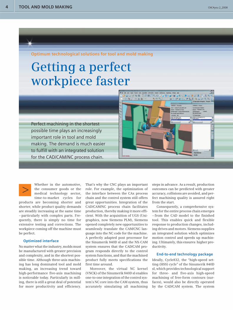
Moreover, the virtual NC kernel (VNCK) of the Sinumerik 840D sl enables one-to-one integration of the control sys-tem’s NC core into the CAM system, thus accurately simulating all machining
TOOL AND MOLD MAKING
steps in advance. As a result, production outcomes can be predicted with greater accuracy, collisions are avoided, and per-fect machining quality is assured right from the start.
Consequently, a comprehensive sys-tem for the entire process chain emerges – from the CAD model to the fi nished tool. This enables quick and fl exible response to production changes, includ-ing drives and motors. Siemens supplies an integrated solution which optimizes motion control and speeds up machin-ing. Ultimately, this ensures higher pro-ductivity.
End-to-end technology package
Ideally, Cycle832, the “high-speed set-ting (HSS) cycle” of the Sinumerik 840D sl, which provides technological support for three- and fi ve-axis high-speed machining of free-form contours (sur-faces), would also be directly operated by the CAD/CAM system. The system
Optimum technological solutions for tool and mold making
Getting a perfect workpiece faster
Perfect machining in the shortest
possible time plays an increasingly
important role in tool and mold
making. The demand is much easier
to fulfi ll with an integrated solution
for the CAD/CAM/NC process chain.

CNC4you 2_2008 5
compiles all of the necessary functions for HSC (high-speed cutting) in a single cycle, provides support in the creation of structured NC programs, and negotiates an ideal compromise between speed, precision and surface quality.
The Sinumerik 840D sl and ShopMill, the operating and programming soft-ware for the shopfl oor, offer tool and
[email protected]/cnc4youFor more information
friendliness is further enhanced with graphical function displays and intuitive input dialogs.
In the unlikely event that there are problems, help is always close at hand – anywhere in the world. That is a real competitive advantage because, in times where cycle times are becoming shorter and shorter, it is crucial that the machine never stands still and that no orders are delayed.
A look to the future
At this year’s EuroMold, Siemens will look to the future and point out in which direction the road for effi cient produc-tion methods such as high-speed cutting (HSC) is headed – not only for medical technology. It is becoming increasingly easier to machine harder materials even faster into precisely molded products with perfect surfaces the fi rst time around. <
mold makers an end-to-end technology package for high-speed cutting that provides optimum support for a wide range of requirements – everything from measuring and setup to programming, data transfer and program exe cution.
The ShopMill interface is extremely user-friendly and can be operated with-out in-depth CNC knowledge. User-
Sinumerik 840D sl:
The highlightsHighly functional and user-friendly for setup and measurements >Flawless workpiece surfaces through excellent motion control and highly >dynamic drives High-level precision through multi-axis kinematic scanning and optional correction >functionality of the slightest errors during machine operationFine-tuned process from the original idea to the fi nished workpiece through >the perfectly tailored Siemens PLM post processors with NX CAM
Precisely simulating all machining steps in advance ensures perfect quality right from the start
Siem
ens
AG
CNC4you 2_20086
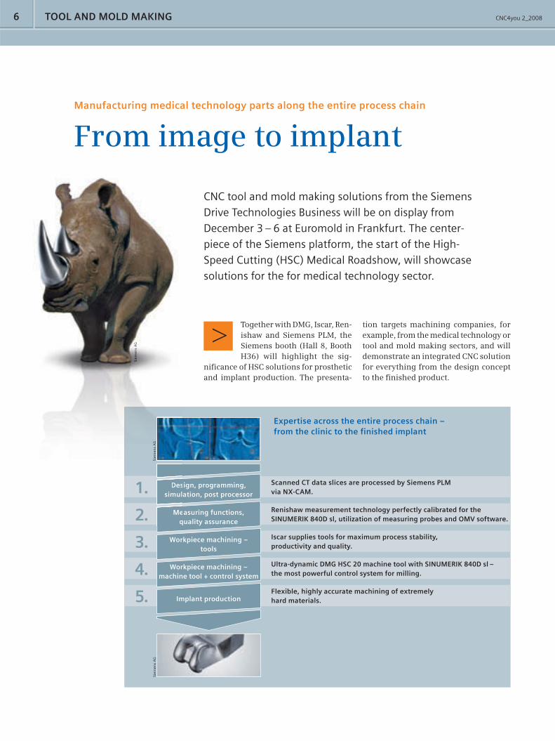
CNC tool and mold making solutions from the Siemens
Drive Technologies Business will be on display from
December 3 – 6 at Euromold in Frankfurt. The center-
piece of the Siemens platform, the start of the High-
Speed Cutting (HSC) Medical Roadshow, will showcase
solutions for the for medical technology sector.
TOOL AND MOLD MAKING
Manufacturing medical technology parts along the entire process chain
From image to implant
Together with DMG, Iscar, Ren-ishaw and Siemens PLM, the Siemens booth (Hall 8, Booth H36) will highlight the sig-
nifi cance of HSC solutions for prosthetic and implant production. The presenta-
tion targets machining companies, for example, from the medical technology or tool and mold making sectors, and will demonstrate an integrated CNC solution for everything from the design concept to the fi nished product.
Siem
ens
AG
Scanned CT data slices are processed by Siemens PLM via NX-CAM.1.
Expertise across the entire process chain – from the clinic to the finished implant
Renishaw measurement technology perfectly calibrated for the SINUMERIK 840D sl, utilization of measuring probes and OMV software.
Iscar supplies tools for maximum process stability, productivity and quality.
Ultra-dynamic DMG HSC 20 machine tool with SINUMERIK 840D sl – the most powerful control system for milling.
Flexible, highly accurate machining of extremely hard materials.
Design, programming, simulation, post processor
Measuring functions, quality assurance
Workpiece machining – tools
Workpiece machining – machine tool + control system
Implant production
2.
3.
4.
5.
Siem
ens
AG
Siem
ens
AG
nnneneeem
emmm
Siem
Siem
Sie
s A
Gs
1. Dessimul
Meq2.
Siem
enie
me
s A
GG
CNC4you 2_2008 7
[email protected]/cnc4youFor more information
The fi nished implant is a perfect fi t
Implants for knee joints are precision machined with the HSC process of Sinumerik 840D sl
>>
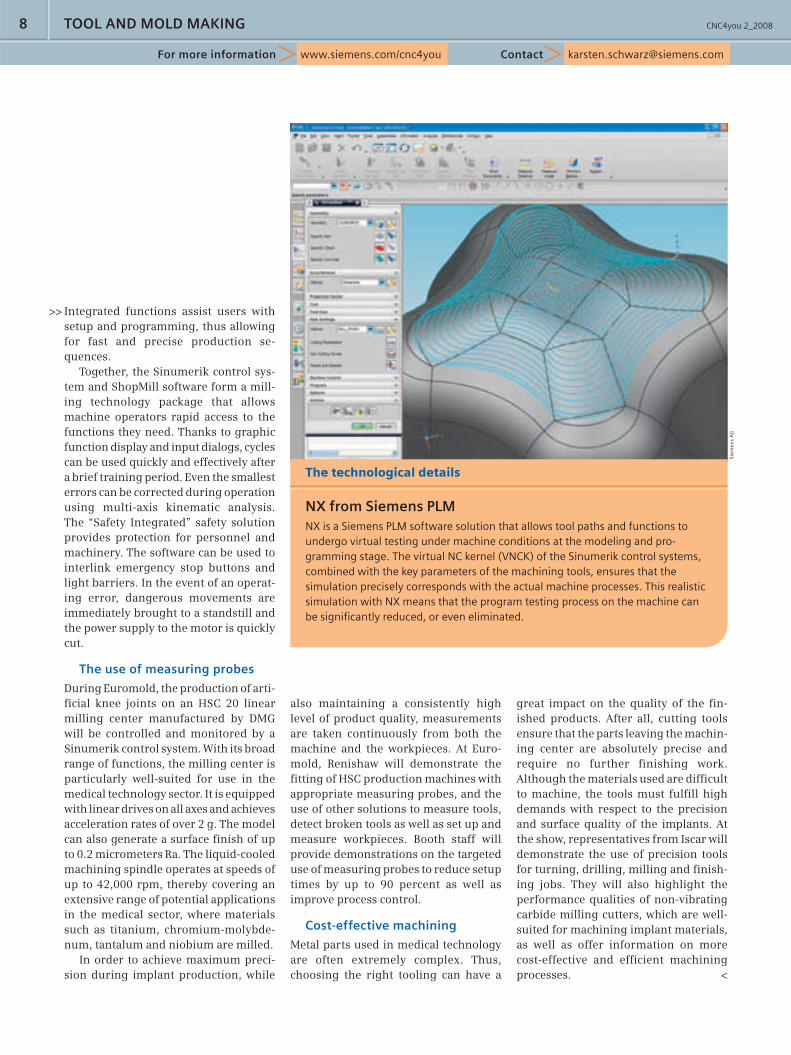
NX from Siemens PLM enables realis-tic simulation of machine functions
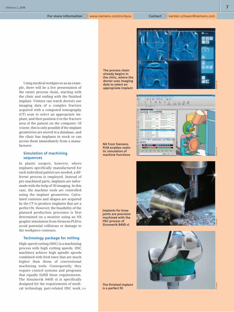
The process chain already begins in the clinic, where the doctor uses imaging data to select an appropriate implant
Using medical workpieces as an exam-ple, there will be a live presentation of the entire process chain, starting with the clinic and ending with the fi nished implant. Visitors can watch doctors use imaging data of a complex fracture acquired with a computed tomography (CT) scan to select an appropriate im-plant, and then position it in the fracture area of the patient on the computer. Of course, this is only possible if the implant geometries are stored in a database, and the clinic has implants in stock or can access them immediately from a manu-facturer.
Simulation of machining sequences
In plastic surgery, however, where implants specifi cally manufactured for each individual patient are needed, a dif-ferent process is employed. Instead of pre-machined parts, implants are tailor-made with the help of 3D imaging. In this case, the machine tools are controlled using the implant geometries. Calcu-lated contours and shapes are acquired by the CT to produce implants that are a perfect fi t. However, the feasibility of the planned production processes is fi rst determined on a monitor using an NX graphic simulation from Siemens PLM to avoid potential collisions or damage to the workpiece contours.
Technology package for milling
High-speed cutting (HSC) is a machining process with high cutting speeds. HSC machines achieve high spindle speeds combined with feed rates that are much higher than those of conventional machining tools. Consequently, they require control systems and programs that equally fulfi ll these requirements. The Sinumerik 840D sl is specifi cally designed for the requirements of medi-cal technology part-related HSC work. P.
Ko
erb
erP.
Ko
erb
erSi
emen
s A
GSi
emen
s A
G
CNC4you 2_20088
Integrated functions assist users with setup and programming, thus allowing for fast and precise production se-quences.
Together, the Sinumerik control sys-tem and ShopMill software form a mill-ing technology package that allows machine operators rapid access to the functions they need. Thanks to graphic function display and input dialogs, cycles can be used quickly and effectively after a brief training period. Even the smallest errors can be corrected during operation using multi-axis kinematic analysis. The “Safety Integrated” safety solution provides protection for personnel and machinery. The software can be used to interlink emergency stop buttons and light barriers. In the event of an operat-ing error, dangerous movements are immediately brought to a standstill and the power supply to the motor is quickly cut.
The use of measuring probes
During Euromold, the production of arti-fi cial knee joints on an HSC 20 linear milling center manufactured by DMG will be controlled and monitored by a Sinumerik control system. With its broad range of functions, the milling center is particularly well-suited for use in the medical technology sector. It is equipped with linear drives on all axes and achieves acceleration rates of over 2 g. The model can also generate a surface fi nish of up to 0.2 micrometers Ra. The liquid-cooled machining spindle operates at speeds of up to 42,000 rpm, thereby covering an extensive range of potential applications in the medical sector, where materials such as titanium, chromium-molybde-num, tantalum and niobium are milled.
In order to achieve maximum preci-sion during implant production, while
also maintaining a consistently high level of product quality, measurements are taken continuously from both the machine and the workpieces. At Euro-mold, Renishaw will demonstrate the fi tting of HSC production machines with appropriate measuring probes, and the use of other solutions to measure tools, detect broken tools as well as set up and measure workpieces. Booth staff will provide demonstrations on the targeted use of measuring probes to reduce setup times by up to 90 percent as well as improve process control.
Cost-effective machining
Metal parts used in medical technology are often extremely complex. Thus, choosing the right tooling can have a
[email protected]/cnc4youFor more information
TOOL AND MOLD MAKING
great impact on the quality of the fi n-ished products. After all, cutting tools ensure that the parts leaving the machin-ing center are absolutely precise and require no further fi nishing work. Although the materials used are diffi cult to machine, the tools must fulfi ll high demands with respect to the precision and surface quality of the implants. At the show, representatives from Iscar will demonstrate the use of precision tools for turning, drilling, milling and fi nish-ing jobs. They will also highlight the performance qualities of non-vibrating carbide milling cutters, which are well-suited for machining implant materials, as well as offer information on more cost-effective and effi cient machining processes. <
>>
The technological details
NX from Siemens PLMNX is a Siemens PLM software solution that allows tool paths and functions to undergo virtual testing under machine conditions at the modeling and pro-gramming stage. The virtual NC kernel (VNCK) of the Sinumerik control systems, combined with the key parameters of the machining tools, ensures that the simulation precisely corresponds with the actual machine processes. This realistic simulation with NX means that the program testing process on the machine can be signifi cantly reduced, or even eliminated.
Siem
ens
AG

CNC4you 2_2008 9
[email protected]/cnc4youFor more information
Precision machining tools for medical technology
Built tough
The production of medical components
from titanium and other rustproof materials
places high demands on machining tools.
Ettlingen-based tool supplier Iscar offers a broad
range of machining tools capable of handling such
tasks – for turning, milling, drilling, countersinking
and tapping of forged blanks and parts made from
drawn solid materials, as well as tools for contour
fi nishing and for rough and fi nish work.
Titanium is one of the key materials used in medical technology. Tools used for machining hard-to-cut titanium blanks are sub-ject to high levels of continuous stress. This accelerates tool wear, potentially causing them to fail. For titanium machining,
Iscar relies on materials such as very fi ne-grain and ultra-fi ne-grain sub-strates. For fi nish work, it also uses cutting inserts with polycrystalline diamond (PCD) particles.
Rustproof stainless steels contain varying amounts of chromium, nickel, molybdenum, manganese and niobium. Contrary to the obvious mechanical, hygienic and medical technological advantages of rustproof materials, they are diffi cult to machine. They are poor heat conductors, resulting in high temperatures and rapid wear on the tool blades. To machine rustproof metals, manufacturers use various combinations of cutter material substrate, coating, geometry and fi nish that are very sim-ilar to those used for tools in titanium machining.
More cutting edges – short machining times
Joint components for hips, shoulders, spinal columns, elbows and hands are generally milled from solid blanks, either as individual parts, or in very small volumes. Knee joints are also produced in larger volumes, whereby the workpieces are pre-fabricated through reshaping. The mill-ing work is generally carried out on three- to fi ve-axis machining cen-ters.
Companies such as Iscar supply solid carbide milling tools specifi cally designed for tool and mold making. Solid carbide end cutters, spherical cutters and toroidal cutters made from ultra-fi ne-grain substrates typi-cally have a large number of cutting edges. The higher the number of cutting edges, the shorter the machining time, and the longer the service life. <
gy
ts
terials
ols.
ers a broaadddd
andliingng s sucuch
unterssininkikingng
s made from
for contour
k.
ISC
AR
CNC4you 2_200810 TOOL AND MOLD MAKING
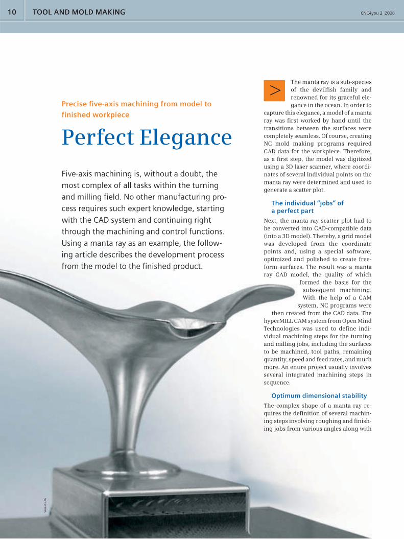
Precise fi ve-axis machining from model to
fi nished workpiece
Perfect Elegance
Siem
ens
AG
Five-axis machining is, without a doubt, the
most complex of all tasks within the turning
and milling fi eld. No other manufacturing pro-
cess requires such expert knowledge, starting
with the CAD system and continuing right
through the machining and control functions.
Using a manta ray as an example, the follow-
ing article describes the development process
from the model to the fi nished product.
The manta ray is a sub-species of the devilfi sh family and renowned for its graceful ele-gance in the ocean. In order to
capture this elegance, a model of a manta ray was fi rst worked by hand until the transitions between the surfaces were completely seamless. Of course, creating NC mold making programs required CAD data for the workpiece. Therefore, as a fi rst step, the model was digitized using a 3D laser scanner, where coordi-nates of several individual points on the manta ray were determined and used to generate a scatter plot.
The individual “jobs” of a perfect part
Next, the manta ray scatter plot had to be converted into CAD-compatible data (into a 3D model). Thereby, a grid model was developed from the coordinate points and, using a special software, optimized and polished to create free-form surfaces. The result was a manta ray CAD model, the quality of which
formed the basis for the subsequent machining. With the help of a CAM
system, NC programs were then created from the CAD data. The
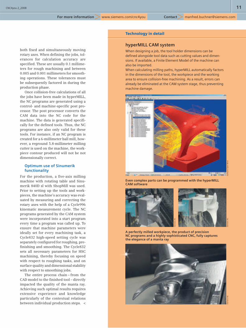
hyperMILL CAM system from Open Mind Technologies was used to defi ne indi-vidual machining steps for the turning and milling jobs, including the surfaces to be machined, tool paths, remaining quantity, speed and feed rates, and much more. An entire project usually involves several integrated machining steps in sequence.
Optimum dimensional stability
The complex shape of a manta ray re-quires the defi nition of several machin-ing steps involving roughing and fi nish-ing jobs from various angles along with
CNC4you 2_2008 11
For more information Contact [email protected]/cnc4you
both fi xed and simultaneously moving rotary axes. When defi ning the jobs, tol-erances for calculation accuracy are specifi ed. These are usually 0.1 millime-ters for rough machining and between 0.005 and 0.001 millimeters for smooth-ing operations. These tolerances must be subsequently factored in during the production phase.
Once collision-free calculations of all the jobs have been made in hyperMILL, the NC programs are generated using a control- and machine-specifi c post pro-cessor. The post processor converts the CAM data into the NC code for the machine. The data is generated specifi -cally for the defi ned tools. Thus, the NC programs are also only valid for these tools. For instance, if an NC program is created for a 6-millimeter ball mill, how-ever, a reground 5.8-millimeter milling cutter is used on the machine, the work-piece contour produced will not be not dimensionally correct.
Optimum use of Sinumerik functionality
For the production, a fi ve-axis milling machine with rotating table and Sinu-merik 840D sl with ShopMill was used. Prior to setting up the tools and work-pieces, the machine’s accuracy was eval-uated by measuring and correcting the rotary axes with the help of a Cycle996 kinematic measurement cycle. The NC programs generated by the CAM system were incorporated into a start program every time a program was called up. To ensure that machine parameters were ideally set for every machining task, a Cycle832 high-speed setting cycle was separately confi gured for roughing, pre-fi nishing and smoothing. The Cycle832 sets all necessary parameters for HSC machining, thereby focusing on speed with respect to roughing tasks, and on surface quality and dimensional stability with respect to smoothing jobs.
The entire process chain – from the CAD model to the fi nished tool – directly impacted the quality of the manta ray. Achieving such optimal results requires extensive experience and knowledge particularly of the contextual relations between individual production steps. <
Even complex parts can be programmed with the hyperMILL CAM software
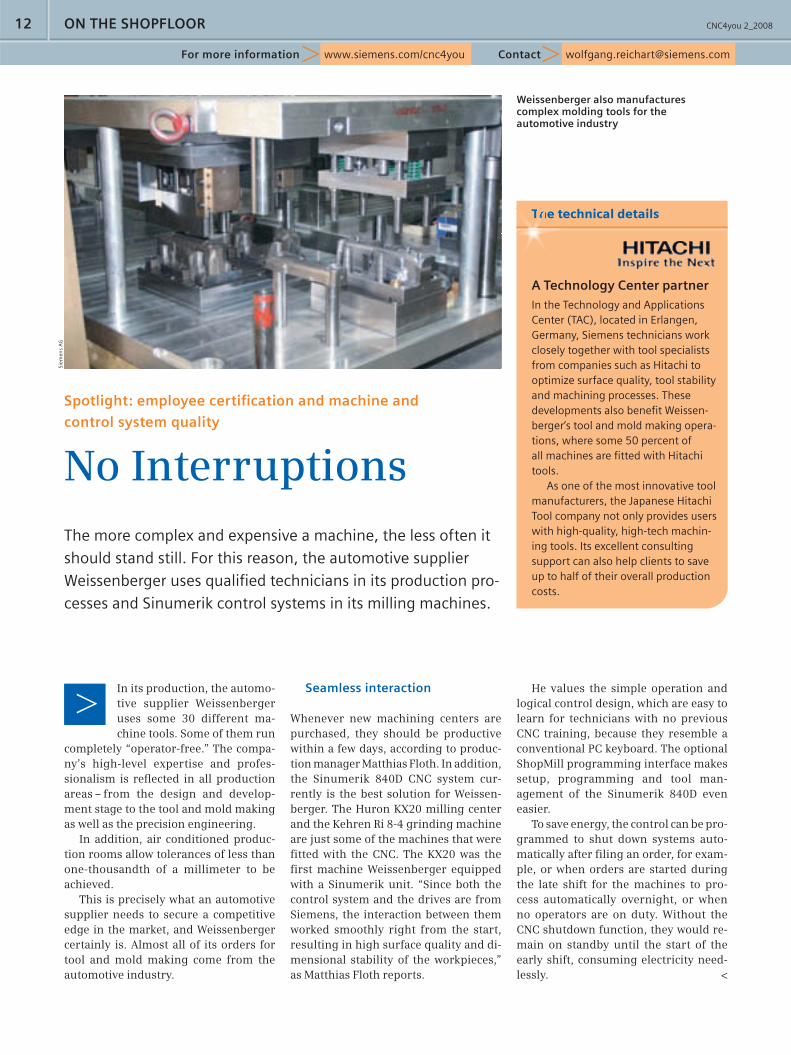
A perfectly milled workpiece, the product of precision NC programs and a highly sophisticated CNC, fully captures the elegance of a manta ray
Technology in detail
hyperMILL CAM systemWhen designing a job, the tool holder dimensions can be defi ned alongside tool data such as cutting values and dimen-sions. If available, a Finite Element Model of the machine can also be imported.When calculating milling paths, hyperMILL automatically factors in the dimensions of the tool, the workpiece and the working area to ensure collision-free machining. As a result, errors can already be eliminated at the CAM system stage, thus preventing machine damage.
Soft
war
e O
pen
Min
d
Siem
ens
AG
Siem
ens
AG
Siem
ens
AG
CNC4you 2_200812
[email protected]/cnc4youFor more information
Seamless interaction
Whenever new machining centers are purchased, they should be productive within a few days, according to produc-tion manager Matthias Floth. In addition, the Sinumerik 840D CNC system cur-rently is the best solution for Weissen-berger. The Huron KX20 milling center and the Kehren Ri 8-4 grinding machine are just some of the machines that were fi tted with the CNC. The KX20 was the fi rst machine Weissenberger equipped with a Sinu merik unit. “Since both the control system and the drives are from Siemens, the interaction between them worked smoothly right from the start, resulting in high surface quality and di-mensional stability of the workpieces,” as Matthias Floth reports.
ON THE SHOPFLOOR
Spotlight: employee certifi cation and machine and
control system quality
No InterruptionsThe more complex and expensive a machine, the less often it
should stand still. For this reason, the automotive supplier
Weissenberger uses qualifi ed technicians in its production pro-
cesses and Sinumerik control systems in its milling machines.
The technical details
A Technology Center partnerIn the Technology and Applications Center (TAC), located in Erlangen, Germany, Siemens technicians work closely together with tool specialists from companies such as Hitachi to optimize surface quality, tool stability and machining processes. These developments also benefi t Weissen-berger‘s tool and mold making opera-tions, where some 50 percent of all machines are fi tted with Hitachi tools.
As one of the most innovative tool manufacturers, the Japanese Hitachi Tool company not only provides users with high-quality, high-tech machin-ing tools. Its excellent consulting support can also help clients to save up to half of their overall production costs.
He values the simple operation and logical control design, which are easy to learn for technicians with no previous CNC training, because they resemble a conventional PC keyboard. The optional ShopMill programming interface makes setup, programming and tool man-agement of the Sinumerik 840D even easier.
To save energy, the control can be pro-grammed to shut down systems auto-matically after fi ling an order, for exam-ple, or when orders are started during the late shift for the machines to pro-cess automatically overnight, or when no operators are on duty. Without the CNC shutdown function, they would re-main on standby until the start of the early shift, consuming electricity need-lessly. <
Weissenberger also manufactures complex molding tools for the automotive industry
ThThThThThh
Siem
ens
AG
In its production, the automo-tive supplier Weissenberger uses some 30 different ma-chine tools. Some of them run
completely “operator-free.” The compa-ny’s high-level expertise and profes-sionalism is refl ected in all production areas – from the design and develop-ment stage to the tool and mold making as well as the precision engineering.
In addition, air conditioned produc-tion rooms allow tolerances of less than one-thousandth of a millimeter to be achieved.
This is precisely what an automotive supplier needs to secure a competitive edge in the market, and Weissenberger certainly is. Almost all of its orders for tool and mold making come from the automotive industry.
When you think of competitive archery, you immedi-
ately think of high-tech bows made from special
materials. However, there are traditional archers who
still prefer conventional wooden bows, but who are,
by all means, open to modern milling technology.
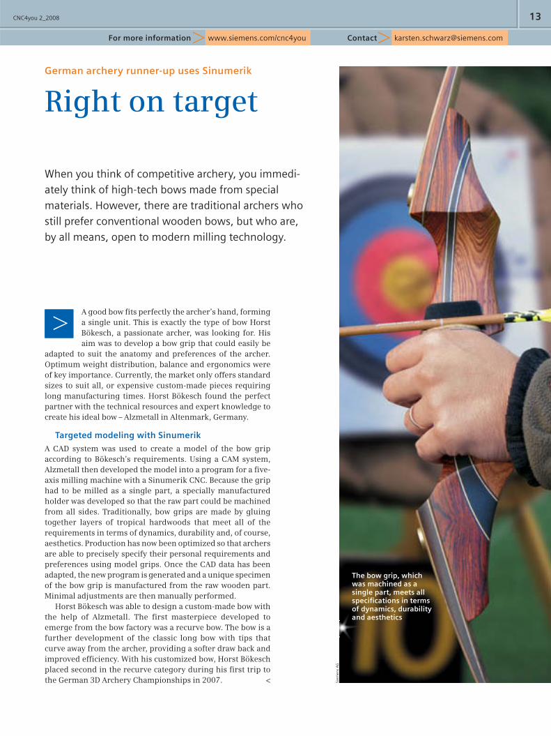
A good bow fi ts perfectly the archer’s hand, forming a single unit. This is exactly the type of bow Horst Bökesch, a passionate archer, was looking for. His aim was to develop a bow grip that could easily be
adapted to suit the anatomy and preferences of the archer. Optimum weight distribution, balance and ergonomics were of key importance. Currently, the market only offers standard sizes to suit all, or expensive custom-made pieces requiring long manufacturing times. Horst Bökesch found the perfect partner with the technical resources and expert knowledge to create his ideal bow – Alzmetall in Altenmark, Germany.
Targeted modeling with Sinumerik
A CAD system was used to create a model of the bow grip according to Bökesch’s requirements. Using a CAM system, Alzmetall then developed the model into a program for a fi ve-axis milling machine with a Sinumerik CNC. Because the grip had to be milled as a single part, a specially manufactured holder was developed so that the raw part could be machined from all sides. Traditionally, bow grips are made by gluing together layers of tropical hardwoods that meet all of the requirements in terms of dynamics, durability and, of course, aesthetics. Production has now been optimized so that archers are able to precisely specify their personal requirements and preferences using model grips. Once the CAD data has been adapted, the new program is generated and a unique specimen of the bow grip is manufactured from the raw wooden part. Minimal adjustments are then manually performed.
Horst Bökesch was able to design a custom-made bow with the help of Alzmetall. The fi rst masterpiece developed to emerge from the bow factory was a recurve bow. The bow is a further development of the classic long bow with tips that curve away from the archer, providing a softer draw back and improved effi ciency. With his customized bow, Horst Bökesch placed second in the recurve category during his fi rst trip to the German 3D Archery Championships in 2007. < Si
emen
s A
G
CNC4you 2_2008 13
[email protected]/cnc4youFor more information
German archery runner-up uses Sinumerik
Right on target
The bow grip, which was machined as a single part, meets all specifi cations in terms of dynamics, durability and aesthetics
CNC4you 2_200814 TIPS & TRICKS
Profi table machines thanks to dimensionally stable workpieces
Precise positioningWhether for recording a wide range of workpiece geometries during setup in
JOG mode, or for automatic dimension control during the machining process,
Sinumerik offers an ideal solution with its confi gurable measuring cycles.
Measuring cycle for the Sinumerik 840D sl
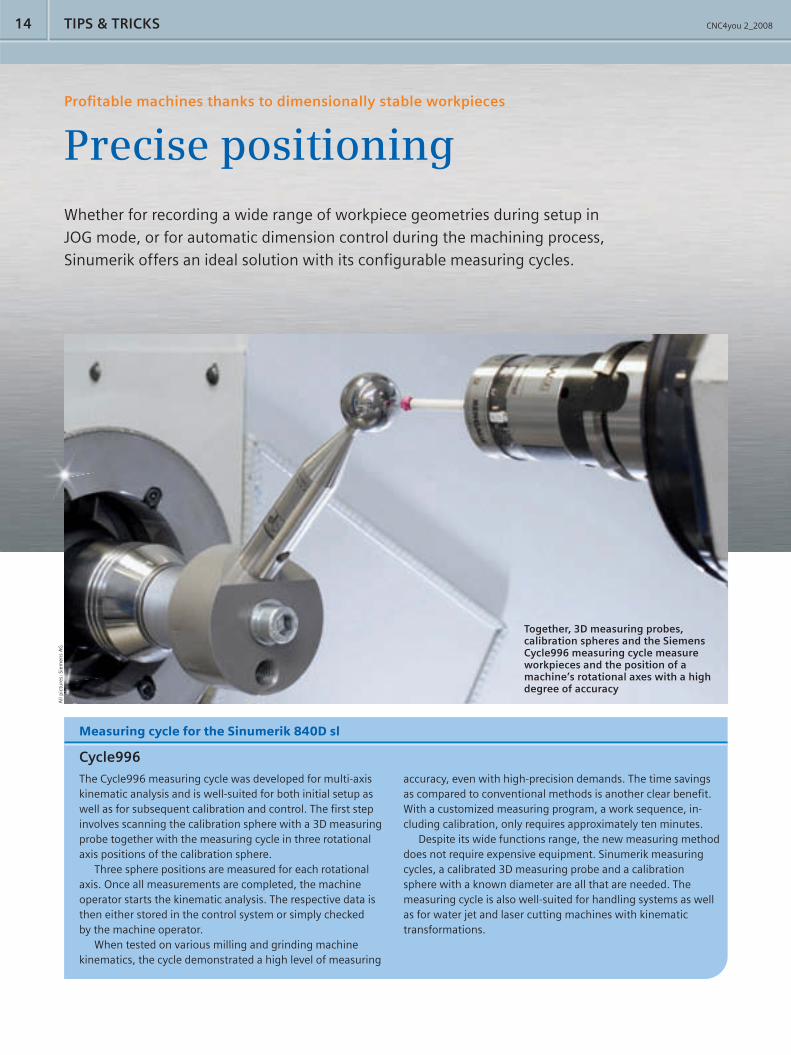
Cycle996The Cycle996 measuring cycle was developed for multi-axis kinematic analysis and is well-suited for both initial setup as well as for subsequent calibration and control. The fi rst step involves scanning the calibration sphere with a 3D measuring probe together with the measuring cycle in three rotational axis positions of the calibration sphere.
Three sphere positions are measured for each rotational axis. Once all measurements are completed, the machine operator starts the kinematic analysis. The respective data is then either stored in the control system or simply checked by the machine operator.
When tested on various milling and grinding machine kinematics, the cycle demonstrated a high level of measuring
accuracy, even with high-precision demands. The time savings as compared to conventional methods is another clear benefi t. With a customized measuring program, a work sequence, in-cluding calibration, only requires approximately ten minutes.
Despite its wide functions range, the new measuring method does not require expensive equipment. Sinumerik measuring cycles, a calibrated 3D measuring probe and a calibration sphere with a known diameter are all that are needed. The measuring cycle is also well-suited for handling systems as well as for water jet and laser cutting machines with kinematic transformations.
Together, 3D measuring probes, calibration spheres and the Siemens Cycle996 measuring cycle measure workpieces and the position of a machine’s rotational axes with a high degree of accuracy
All
pic
ture
s: S
iem
ens
AG
CNC4you 2_2008 15
[email protected]/cnc4youFor more information
>>
In CNC production, it is still common to measure tools and workpieces by hand on the machine. The zero point is de-
termined by scratching and the values obtained are entered manually into the CNC system. Not only is this method prone to error, it is often expensive and time-consuming, and requires a steady hand. The use of a measuring probe and Sinumerik measuring cycles makes life much easier.
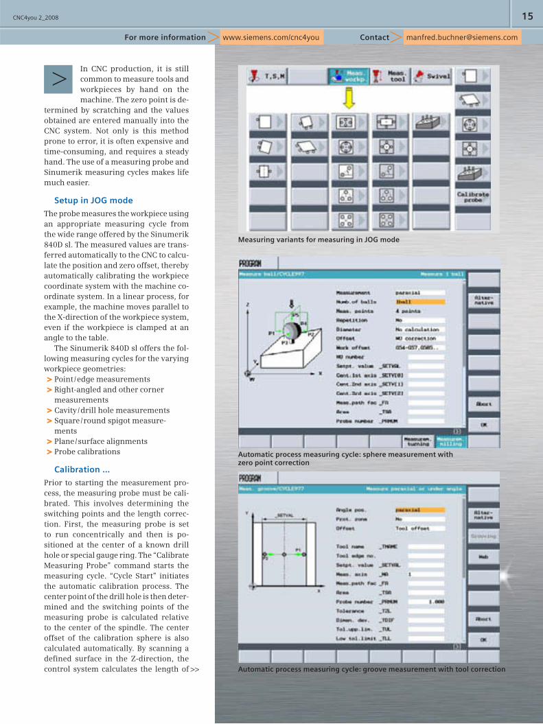
Setup in JOG mode
The probe measures the workpiece using an appropriate measuring cycle from the wide range offered by the Sinumerik 840D sl. The measured values are trans-ferred automatically to the CNC to calcu-late the position and zero offset, thereby automatically calibrating the workpiece coordinate system with the machine co-ordinate system. In a linear process, for example, the machine moves parallel to the X-direction of the workpiece system, even if the workpiece is clamped at an angle to the table.
The Sinumerik 840D sl offers the fol-lowing measuring cycles for the varying workpiece geometries:
Point / edge measurements >Right-angled and other corner >measurementsCavity / drill hole measurements >Square / round spigot measure- >mentsPlane / surface alignments >Probe calibrations >
Calibration …
Prior to starting the measurement pro-cess, the measuring probe must be cali-brated. This involves determining the switching points and the length correc-tion. First, the measuring probe is set to run concentrically and then is po-sitioned at the center of a known drill hole or special gauge ring. The “Calibrate Measuring Probe” command starts the measuring cycle. “Cycle Start” initiates the automatic calibration process. The center point of the drill hole is then deter-mined and the switching points of the measuring probe is calculated relative to the center of the spindle. The center offset of the calibration sphere is also calculated automatically. By scanning a defi ned surface in the Z-direction, the control system calculates the length of
Measuring variants for measuring in JOG mode
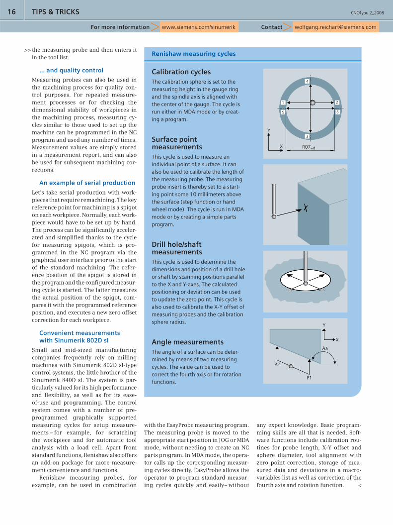
Automatic process measuring cycle: sphere measurement with zero point correction
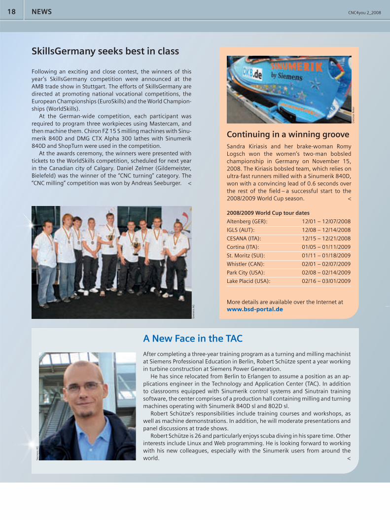
Automatic process measuring cycle: groove measurement with tool correction
CNC4you 2_200816
the measuring probe and then enters it in the tool list.
… and quality control
Measuring probes can also be used in the machining process for quality con-trol purposes. For repeated measure-ment processes or for checking the dimensional stability of workpieces in the machining process, measuring cy-cles similar to those used to set up the machine can be programmed in the NC program and used any number of times. Measurement values are simply stored in a measurement report, and can also be used for subsequent machining cor-rections.
An example of serial production
Let’s take serial production with work-pieces that require remachining. The key reference point for machining is a spigot on each workpiece. Normally, each work-piece would have to be set up by hand. The process can be signifi cantly acceler-ated and simplifi ed thanks to the cycle for measuring spigots, which is pro-grammed in the NC program via the graphical user interface prior to the start of the standard machining. The refer-ence position of the spigot is stored in the program and the confi gured measur-ing cycle is started. The latter measures the actual position of the spigot, com-pares it with the programmed reference position, and executes a new zero offset correction for each workpiece.
Convenient measurements with Sinumerik 802D sl
Small and mid-sized manufacturing companies frequently rely on milling machines with Sinumerik 802D sl-type control systems, the little brother of the Sinumerik 840D sl. The system is par-ticularly valued for its high performance and fl exibility, as well as for its ease-of-use and programming. The control system comes with a number of pre-programmed graphically supported measuring cycles for setup measure-ments – for example, for scratching the workpiece and for automatic tool analysis with a load cell. Apart from standard functions, Renishaw also offers an add-on package for more measure-ment convenience and functions.
Renishaw measuring probes, for example, can be used in combination
with the EasyProbe measuring program. The measuring probe is moved to the appropriate start position in JOG or MDA mode, without needing to create an NC parts program. In MDA mode, the opera-tor calls up the corresponding measur-ing cycles directly. EasyProbe allows the operator to program standard measur-ing cycles quickly and easily– without
[email protected]/sinumerikFor more information
TIPS & TRICKS
any expert knowledge. Basic program-ming skills are all that is needed. Soft-ware functions include calibration rou-tines for probe length, X-Y offset and sphere diameter, tool alignment with zero point correction, storage of mea-sured data and deviations in a macro-variables list as well as correction of the fourth axis and rotation function. <
>>Renishaw measuring cycles
Calibration cyclesThe calibration sphere is set to the measuring height in the gauge ring and the spindle axis is aligned with the center of the gauge. The cycle is run either in MDA mode or by creat-ing a program.
Surface point measurementsThis cycle is used to measure an individual point of a surface. It can also be used to calibrate the length of the measuring probe. The measuring probe insert is thereby set to a start-ing point some 10 millimeters above the surface (step function or hand wheel mode). The cycle is run in MDA mode or by creating a simple parts program.
Drill hole/shaft measurementsThis cycle is used to determine the dimensions and position of a drill hole or shaft by scanning positions parallel to the X and Y-axes. The calculated positioning or deviation can be used to update the zero point. This cycle is also used to calibrate the X-Y offset of measuring probes and the calibration sphere radius.
Angle measurementsThe angle of a surface can be deter-mined by means of two measuring cycles. The value can be used to correct the fourth axis or for rotation functions.
1 2
4
3
Y
X R07=d
65
Y
X
P2
P1
Aa

CNC4you 2_2008 17
[email protected]/cnc4youFor more information
Sample protocol defi nition with comments
Protocol fi le with protocol header and measurement values from two measuring cycles
In automatic measurement, the dimensions of work-piece geometries are determined by means of pre-confi gured measuring cycles. The optionally enabled Cycle100 protocol function stores these measure-
ment values as a table overview in a fi le. The data can be viewed directly on the control system, or read and edited as an ASCII fi le by any text editor or spreadsheet program. The protocol fi le comes particularly in handy with workpieces destined for further processing on another machine, such as a grinding machine or for documentation purposes.
No special protocol specifi cations must be taken into con-sideration when programming the measuring cycles. Creating a program for the protocol format or adding the format to the parts program is all that is needed. The program is located in the same folder as the parts program for the measurement process. The protocol fi le containing the measurement values is also stored there. Exporting the protocol format to another program has also proven to be very useful. The protocol is de-fi ned in the program, and the parts program is activated after starting the Cycle100 protocol cycle. The protocol is ended fol-lowing the Cycle101 mesurement.
The technical details
The protocol, for example, is defi ned in a “Report_Var.MPF” program. First, the protocol fi le format is defi ned, including number of lines, number of characters, page number and col-umn width. The parameters for the protocol content describe the table headings, its content and the protocol header. Once the protocol format and content have been defi ned, the “Mea-suring program_1” parts program for the measurement is acti-vated, run and switched off, when completed. The program then automatically creates a protocol fi le, “Protocol_1,” con-taining all measurement values. <
Creating measurement reports with the Cycle100 and 101 functions
Automatic quality protocols
Measuring cycles, the little helpers of
automatic measurement processes, control
the dimensional stability of workpieces.
In addition to measuring, however, they
can also automatically generate and store
a measurement protocol.
;=================== PROTOKOLL =======================
;---------PARAMETER FUER PROTOKOLLFORMAT--------------
_PROTFORM[0]=50 ;ZEILEN PRO SEITE
_PROTFORM[1]=100 ;ZEICHEN PRO ZEILE
_PROTFORM[2]=1 ;ERSTE SEITENNUMMER
_PROTFORM[3]=4 ;ANZAHL PROTOKOLL KOPFZEILEN
_PROTFORM[4]=1 ;ANZAHL WERTEZEILE IM PROTOKOLL
_PROTFORM[5]=12 ;SPALTENBREITE (ZEICHENANZAHL)
_PROTSYM[0]="|" ;TRENNZEICHEN SPALTEN
_PROTSYM[1]="*" ;TOLERANZ-UEBERSCHREITUNG
_DIGIT=4 ;NACHKOMMASTELLEN DER MESSWERTE
; ---------PARAMETER FUER PROTOKOLLINHALT-------------
_PROTNAME[0]="PROT_VAR" ;NAME PROTOKOLLFORMAT
_PROTNAME[1]="PROTOKOLL_1" ;NAME PROTOKOLLDATEI
;UEBERSCHRIFTEN DER TABELLE IM PROTOKOLL
_PROTVAL[0]="MESSUNG,ACHSE,SOLLWERT,ISTWERT"
_PROTVAL[1]=" , , , "
;WERTEZEILEN <=> _PROTFORM[4]
_PROTVAL[2]="_TXT[0],R2,_OVR[0],_OVR[4]"
_PROTVAL[3]=""
_PROTVAL[4]=""
_PROTVAL[5]=""
;ANWENDERZEILEN PROTOKOLLKOPF <=> _PROTFORM[3]
_HEADLINE[0]="TEILENUMMER : 1234"
_HEADLINE[1]="BESTELLNUMMER: 6789"
_HEADLINE[2]="BEARBEITER : SIEMENS AG"
_HEADLINE[3]=""
_TXT[0]=<<TRUNC(R10) ;GANZZAHLIGE ANZEIGE DES MP
_CBIT[6]=0 ;MIT ZYKLUSNAME UND MESSVARIANTE
_CBIT[11]=0 ;STANDARD-PROTOKOLLKOPF
; --------- AUFRUF DES MESSPROGRAMM_1 ----------------
CYCLE100 ;PROTOKOLLIEREN EIN
MESSPROGRAMM_1
CYCLE101 ;PROTOKOLLIEREN AUS
M30
Siem
ens
AG
CNC4you 2_200818 NEWS
SkillsGermany seeks best in class
Following an exciting and close contest, the winners of this year’s SkillsGermany competition were announced at the AMB trade show in Stuttgart. The efforts of SkillsGermany are directed at promoting national vocational competitions, the European Championships (EuroSkills) and the World Champion-ships (WorldSkills).
At the German-wide competition, each participant was required to program three workpieces using Mastercam, and then machine them. Chiron FZ 15 S milling machines with Sinu-merik 840D and DMG CTX Alpha 300 lathes with Sinumerik 840D and ShopTurn were used in the competition.
At the awards ceremony, the winners were presented with tickets to the WorldSkills competition, scheduled for next year in the Canadian city of Calgary. Daniel Zelmer (Gildemeister, Bielefeld) was the winner of the “CNC turning” category. The “CNC milling” competition was won by Andreas Seeburger. <
A New Face in the TAC
After completing a three-year training program as a turning and milling machinist at Siemens Professional Education in Berlin, Robert Schütze spent a year working in turbine construction at Siemens Power Generation.
He has since relocated from Berlin to Erlangen to assume a position as an ap-plications engineer in the Technology and Application Center (TAC). In addition to classrooms equipped with Sinumerik control systems and Sinutrain training software, the center comprises of a production hall containing milling and turning machines operating with Sinumerik 840D sl and 802D sl.
Robert Schütze’s responsibilities include training courses and workshops, as well as machine demonstrations. In addition, he will moderate presentations and panel discussions at trade shows.
Robert Schütze is 26 and particularly enjoys scuba diving in his spare time. Other interests include Linux and Web programming. He is looking forward to working with his new colleagues, especially with the Sinumerik users from around the world. <
Continuing in a winning grooveSandra Kiriasis and her brake-woman Romy Logsch won the women’s two-man bobsled championship in Germany on November 15, 2008. The Kiriasis bobsled team, which relies on ultra-fast runners milled with a Sinumerik 840D, won with a convincing lead of 0.6 seconds over the rest of the fi eld – a successful start to the 2008/2009 World Cup season. <
2008/2009 World Cup tour dates
Altenberg (GER): 12/01 – 12/07/2008
IGLS (AUT): 12/08 – 12/14/2008
CESANA (ITA): 12/15 – 12/21/2008
Cortina (ITA): 01/05 – 01/11/2009
St. Moritz (SUI): 01/11 – 01/18/2009
Whistler (CAN): 02/01 – 02/07/2009
Park City (USA): 02/08 – 02/14/2009
Lake Placid (USA): 02/16 – 03/01/2009
More details are available over the Internet atwww.bsd-portal.de
Die
tmar
Rek
er
Siem
ens
AG
Siem
ens
AG
CNC4you 2_2008 19
Event Location Dates
EUROMOLD Frankfurt (GER) 12/03 – 12/06/2008
DMG Open House Pfronten (GER) 02/09 – 02/14/2009
MEDTEC Stuttgart (GER) 03/03 – 03/05/2009
Medical show Warsaw (USA) 03/12 – 03/13/2009
Siemens Seminar Erlangen (GER) 03/19 – 03/20/2009
CIMT Beijing (CHN) 04/06 – 04/11/2009
ISCAR Seminar Ettlingen (GER) 05/06 – 05/07/2009
Medical show Memphis (USA) 05/07 – 05/08/2009
mediSIAMS Moutier (SUI) 05/10 – 05/13/2009
Medical show Boston (USA) 06/11 – 06/12/2009
DMG Seminar Geretsried (GER) 07/09 – 07/10/2009
Medical High-Speed Cutting (HSC) RoadshowAt Euromold in Frankfurt, Siemens will kick off an international roadshow together with four strong partners on the topic of high-speed cutting in the fi eld of medical technology. The var-ious planning, development, simulation and production steps along the entire the process chain in medical part production will be demonstrated live – from the clinic to the fi nished implant. <
First “MTT” partnership
In May 2008, Richard Glimpel, a member of the EMUGE Group, became the fi rst tool maker to sign a Siemens Solution Partner contract for the “Machine Tools Technology” module, or MTT for short. The MTT module was developed to foster partnerships and to support cooperation in the areas of technol-ogy and promotion.
The Siemens Solution Partner program aims to promote partnerships between system integrators, systems houses, leading technology providers and Siemens, for the mutual benefi t of all parties. MTT is one of currently three modules within the Industry Sector’s Solution Partner Program. Currently, the program comprises a total of 32 modules, with ap-proximately 1,000 partners.
EMUGE, based in Lauf in the German region of Franconia, has a presence in 42 countries world-wide. As the leader in the fi eld of thread-cutting technology, the company is an important Solution Partner for Siemens in the machining sector. <
Anton Heilmann, OEM manager for EMUGE Franken, and Karsten Schwarz, head of Application Engineer-ing at Siemens Erlangen
www.siemens.com/cnc4youFor more information
Siem
ens
AG
Siem
ens
AG
Answers for industry.
SINUMERIK
The new strength in high-speed-cutting
Precision meets power
Medical workpiece manufacturing requires the utmost precision along with highly dynamic performance. Together with these strong partners for high-speed-cutting – DMG, Iscar and Renishaw – Siemens will show you how such demands can be met. We will present the entire process chain, live during our road show, from the clinic through to the final implant.For more information, visit www.siemens.com/high-speed-cutting