Embed Size (px)
Citation preview
The Serial Peripheral Interface (SPI)
Corrado Santoro
ARSLAB - Autonomous and Robotic Systems LaboratoryDipartimento di Matematica e Informatica - Universita di Catania, Italy
L.S.M. 1 Course
Corrado Santoro The Serial Peripheral Interface
What is SPI?
The SPI—Serial Peripheral Interface is a communication hardwaredesigned to interconnect integrated circuits to a MCU belonging to thesame board.
It has been introduced by Motorola in the ’80s.
Now, it is a standard interface supported by any MCU and many deviceslike sensors, memories (EEPROM, SDCards, etc.), power drivers, etc.
Corrado Santoro The Serial Peripheral Interface
SPI: Philosophy and Connections
SCK
MOSI
SS
SPI Master (MCU)
MISO
SPI Slave (e.g. Sensor)
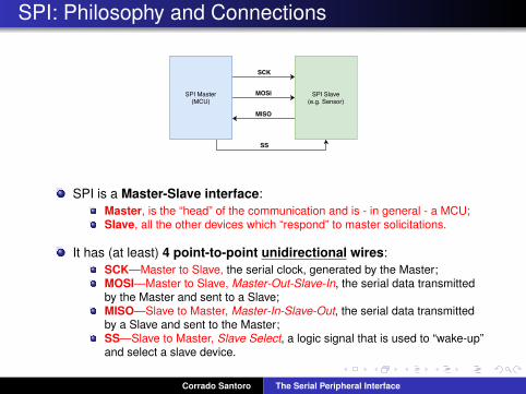
SPI is a Master-Slave interface:Master, is the “head” of the communication and is - in general - a MCU;Slave, all the other devices which “respond” to master solicitations.
It has (at least) 4 point-to-point unidirectional wires:SCK—Master to Slave, the serial clock, generated by the Master;MOSI—Master to Slave, Master-Out-Slave-In, the serial data transmittedby the Master and sent to a Slave;MISO—Slave to Master, Master-In-Slave-Out, the serial data transmittedby a Slave and sent to the Master;SS—Slave to Master, Slave Select, a logic signal that is used to “wake-up”and select a slave device.
Corrado Santoro The Serial Peripheral Interface
SPI: Signals and Timing
SCK
SS
MOSI D0 D1 D2 D3 D4 Dn-1 Dn
MISO D0 D1 D2 D3 D4 Dn-1 Dn
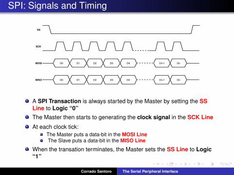
A SPI Transaction is always started by the Master by setting the SSLine to Logic “0”The Master then starts to generating the clock signal in the SCK Line
At each clock tick:The Master puts a data-bit in the MOSI LineThe Slave puts a data-bit in the MISO Line
When the transation terminates, the Master sets the SS Line to Logic“1”
Corrado Santoro The Serial Peripheral Interface
Meaning of Data Bits
SCK
SS
MOSI D0 D1 D2 D3 D4 Dn-1 Dn
MISO D0 D1 D2 D3 D4 Dn-1 Dn
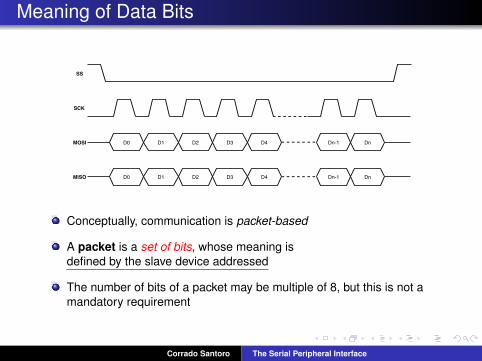
Conceptually, communication is packet-based
A packet is a set of bits, whose meaning isdefined by the slave device addressed
The number of bits of a packet may be multiple of 8, but this is not amandatory requirement
Corrado Santoro The Serial Peripheral Interface
Example: the MCP4921/MCP4922
SPI Interface
Voltage Output
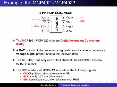
The MCP4921/MCP4922 chip are Digital-to-Analog Converters(DAC)
A DAC is a circuit that receives a digital data and is able to generate avoltage signal proportional to the received data
The MCP4921 has only one output channel, the MCP4922 has twooutput channels
The SPI interface of MCP4921 is made of the following signals:CS, Chip Select, alternative name for SSSCK, the Serial Clock (from master)SDI, Serial Data Input, alternative name for MOSI
Corrado Santoro The Serial Peripheral Interface
Example: the data packet of MCP4921/MCP4922
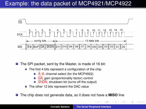
The SPI packet, sent by the Master, is made of 16 bit:The first 4 bits represent a configuration of the chip
A/B, channel select (for the MCP4922)GA, gain (proportionality factor) controlSHDN, shutdown bit (turns off the output)
The other 12 bits represent the DAC value
The chip does not generate data, so it does not have a MISO line
Corrado Santoro The Serial Peripheral Interface
Multiple Slaves: Parallel Connection
SCK
MOSI
SS1
SPI Master (MCU)
MISO
SPI Slave 1
SPI Slave 2
SCK
MOSI
MISO
SS2
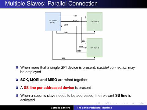
When more that a single SPI device is present, parallel connection maybe employed
SCK, MOSI and MISO are wired together
A SS line per addressed device is present
When a specific slave needs to be addressed, the relevant SS line isactivated
Corrado Santoro The Serial Peripheral Interface
Multiple Slaves: Daisy-Chain Connection
SCK
MOSI
SS
SPI Master (MCU) SPI Slave 1
SPI Slave 2
SCK
MOSI
MISO
SS
MISO
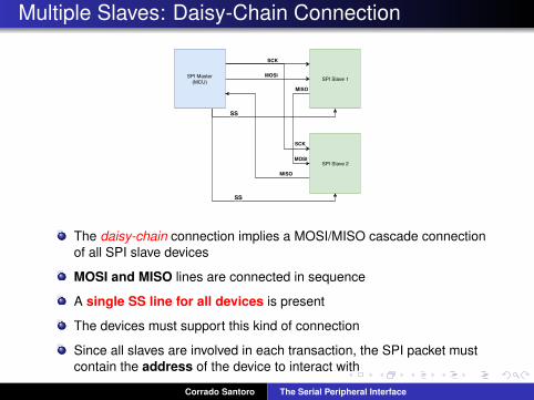
The daisy-chain connection implies a MOSI/MISO cascade connectionof all SPI slave devices
MOSI and MISO lines are connected in sequence
A single SS line for all devices is present
The devices must support this kind of connection
Since all slaves are involved in each transaction, the SPI packet mustcontain the address of the device to interact with
Corrado Santoro The Serial Peripheral Interface
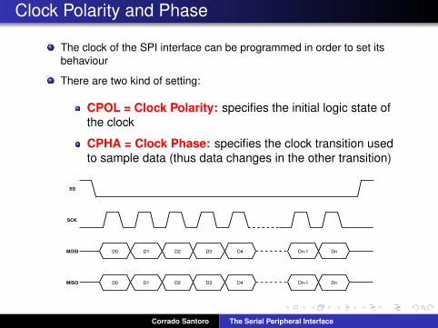
Clock Polarity and Phase
The clock of the SPI interface can be programmed in order to set itsbehaviour
There are two kind of setting:
CPOL = Clock Polarity: specifies the initial logic state ofthe clock
CPHA = Clock Phase: specifies the clock transition usedto sample data (thus data changes in the other transition)
SCK
SS
MOSI D0 D1 D2 D3 D4 Dn-1 Dn
MISO D0 D1 D2 D3 D4 Dn-1 Dn
Corrado Santoro The Serial Peripheral Interface
Clock Polarity and Phase
The clock of the SPI interface can be programmed in order to set itsbehaviour
There are two kind of setting:
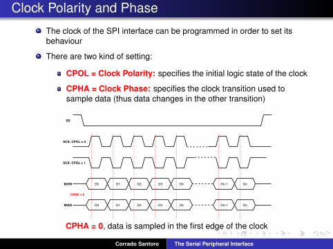
CPOL = Clock Polarity: specifies the initial logic state of the clock
CPHA = Clock Phase: specifies the clock transition used tosample data (thus data changes in the other transition)
SCK, CPOL = 0
SS
MOSI D0 D1 D2 D3 D4 Dn-1 Dn
MISO D0 D1 D2 D3 D4 Dn-1 Dn
SCK, CPOL = 1
CPHA = 0
CPHA = 0, data is sampled in the first edge of the clock
Corrado Santoro The Serial Peripheral Interface
Clock Polarity and Phase
The clock of the SPI interface can be programmed in order to set itsbehaviour
There are two kind of setting:
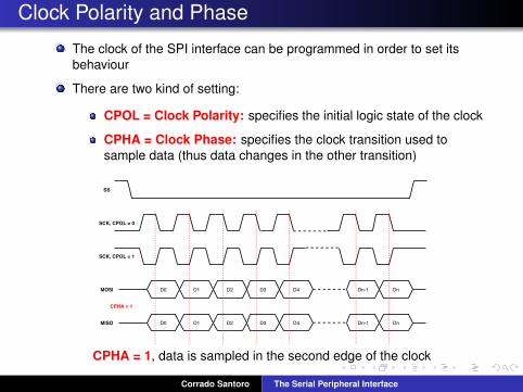
CPOL = Clock Polarity: specifies the initial logic state of the clock
CPHA = Clock Phase: specifies the clock transition used tosample data (thus data changes in the other transition)
SCK, CPOL = 0
SS
MOSI D0 D1 D2 D3 D4 Dn-1 Dn
MISO D0 D1 D2 D3 D4 Dn-1 Dn
SCK, CPOL = 1
CPHA = 1
CPHA = 1, data is sampled in the second edge of the clock
Corrado Santoro The Serial Peripheral Interface
SPI and I2C: Comparison
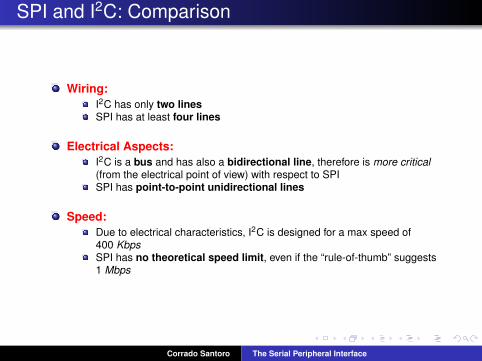
Wiring:I2C has only two linesSPI has at least four lines
Electrical Aspects:I2C is a bus and has also a bidirectional line, therefore is more critical(from the electrical point of view) with respect to SPISPI has point-to-point unidirectional lines
Speed:Due to electrical characteristics, I2C is designed for a max speed of400 KbpsSPI has no theoretical speed limit, even if the “rule-of-thumb” suggests1 Mbps
Corrado Santoro The Serial Peripheral Interface
SPI and I2C: Comparison
Protocol and Addressing:I2C specifies a standard for device addressing and functionalities aremapped to device registersSPI does not define a standard data frame, each device has its own dataformat
Number of supported devices:I2C is a bus and thus it has no theoretical limit on the number of devicesthat can be interconnectedLimits on SPI are defined by the number of SS wires (in case of parallelconnection) or latency (in case of daisy-chain connection)
Corrado Santoro The Serial Peripheral Interface

The Serial Peripheral Interface (SPI)
Corrado Santoro
ARSLAB - Autonomous and Robotic Systems LaboratoryDipartimento di Matematica e Informatica - Universita di Catania, Italy
L.S.M. 1 Course
Corrado Santoro The Serial Peripheral Interface


![AT07890: SAM4 Serial Peripheral Interface (SPI) ASF ...ww1.microchip.com/downloads/en/AppNotes/Atmel... · AT07890: SAM4 Serial Peripheral Interface (SPI) [APPLICATION NOTE] 42290A-MCU-05/2014](https://img.pdfslide.us/doc/110x75/5f5d17292f485424c86f3340/at07890-sam4-serial-peripheral-interface-spi-asf-ww1-at07890-sam4-serial.jpg)