Embed Size (px)
Citation preview
The safety effects of crosslinked polymers
in wire & cable applications
h Cables 2012
AMI
Ron Goethals
Inhol bv, The Netherlands
www.inhol.com
Miami, USA, April 18 & 19, 2012
h Cables 2012
AMI
Main topics
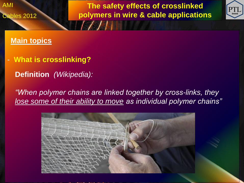
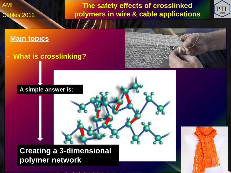
- What is crosslinking?
- A comparison of the 3 main XL-systems in the W & C industry.
- Why can crosslinking make the world safer?
- Global geographical trends in W & C crosslinking.
- Conclusion
The safety effects of crosslinked
polymers in wire & cable applications
h Cables 2012
AMI
Main topics
- What is crosslinking?
\
Definition (Wikipedia):
“When polymer chains are linked together by cross-links, they
lose some of their ability to move as individual polymer chains”
The safety effects of crosslinked
polymers in wire & cable applications
h Cables 2012
AMI
Main topics
- What is crosslinking?
\
Creating a 3-dimensional
polymer network
A simple answer is:
The safety effects of crosslinked
polymers in wire & cable applications
h Cables 2012
AMI
How is crosslinking achieved in the wire & cable industry?
A comparison of the 3 main crosslink systems
* E-beam (or radiation) crosslinking
* CV (or chemical) crosslinking
* Silane (or moisture) crosslinking
Comparison of 3 crosslink systems
h Cables 2012
AMI
How is crosslinking achieved in the wire & cable industry?
A comparison of the 3 main crosslink systems
* Description / Explanation
* Chemistry
* Advantages & Disadvantages
Comparison of 3 crosslink systems
h Cables 2012
AMI
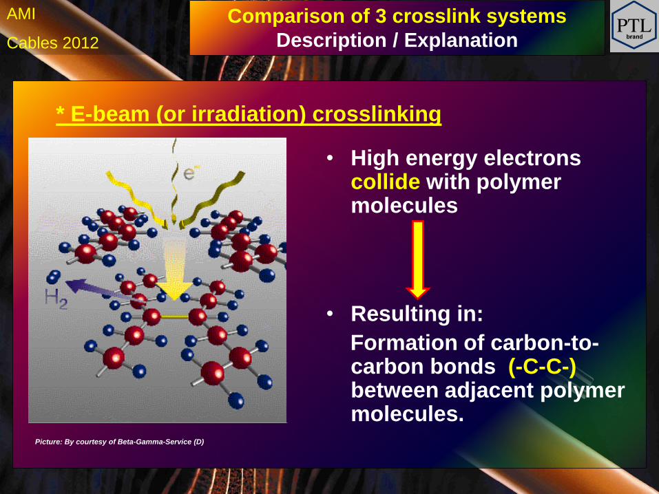
* E-beam (or irradiation) crosslinking
• Resulting in:
Formation of carbon-to- carbon bonds (-C-C-) between adjacent polymer molecules.
• High energy electrons collide with polymer molecules
Picture: By courtesy of Beta-Gamma-Service (D)
Comparison of 3 crosslink systems
Description / Explanation
h Cables 2012
AMI
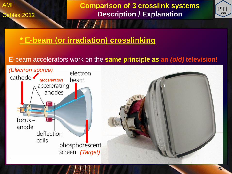
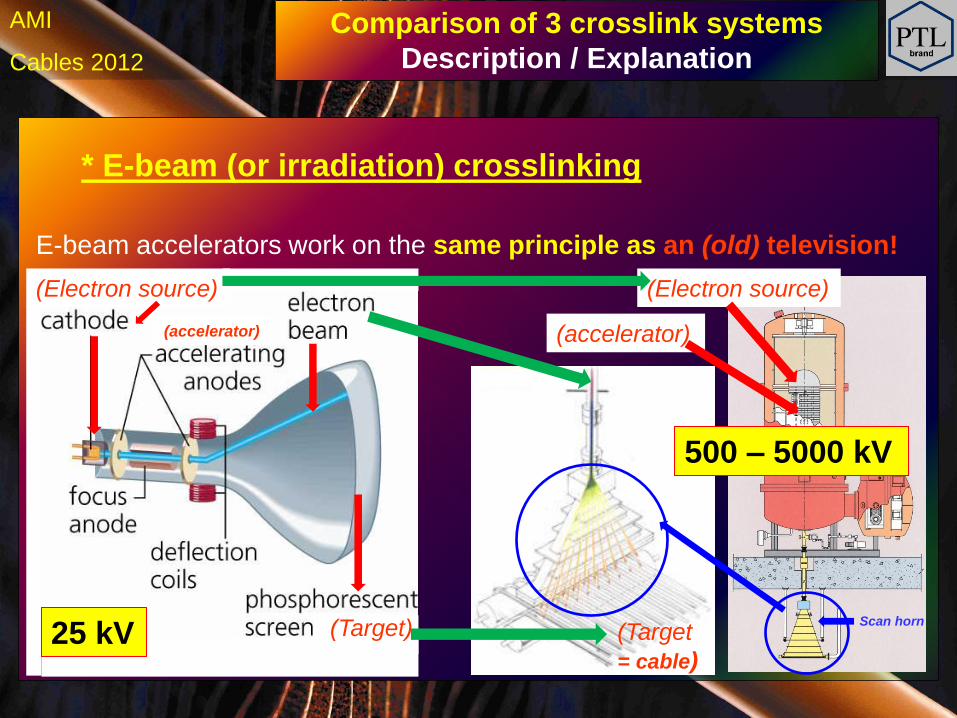
* E-beam (or irradiation) crosslinking
(Target)
(Electron source)
E-beam accelerators work on the same principle as an (old) television!
Comparison of 3 crosslink systems
Description / Explanation
(accelerator)
40
h Cables 2012
AMI
* E-beam (or irradiation) crosslinking
(Electron source) (Electron source)
(accelerator)
(Target
= cable)
E-beam accelerators work on the same principle as an (old) television!
Comparison of 3 crosslink systems
Description / Explanation
(accelerator)
(Target) Scan horn
25 kV
500 – 5000 kV
h Cables 2012
AMI
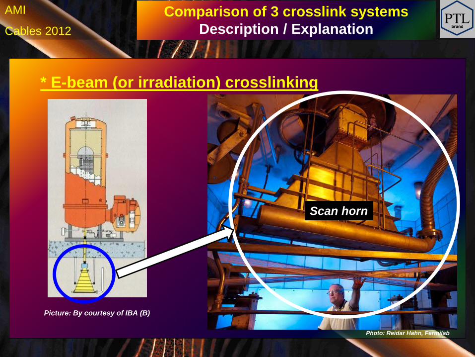
* E-beam (or irradiation) crosslinking
Photo: Reidar Hahn, Fermilab
Scan horn
Comparison of 3 crosslink systems
Description / Explanation
Picture: By courtesy of IBA (B)
h Cables 2012
AMI
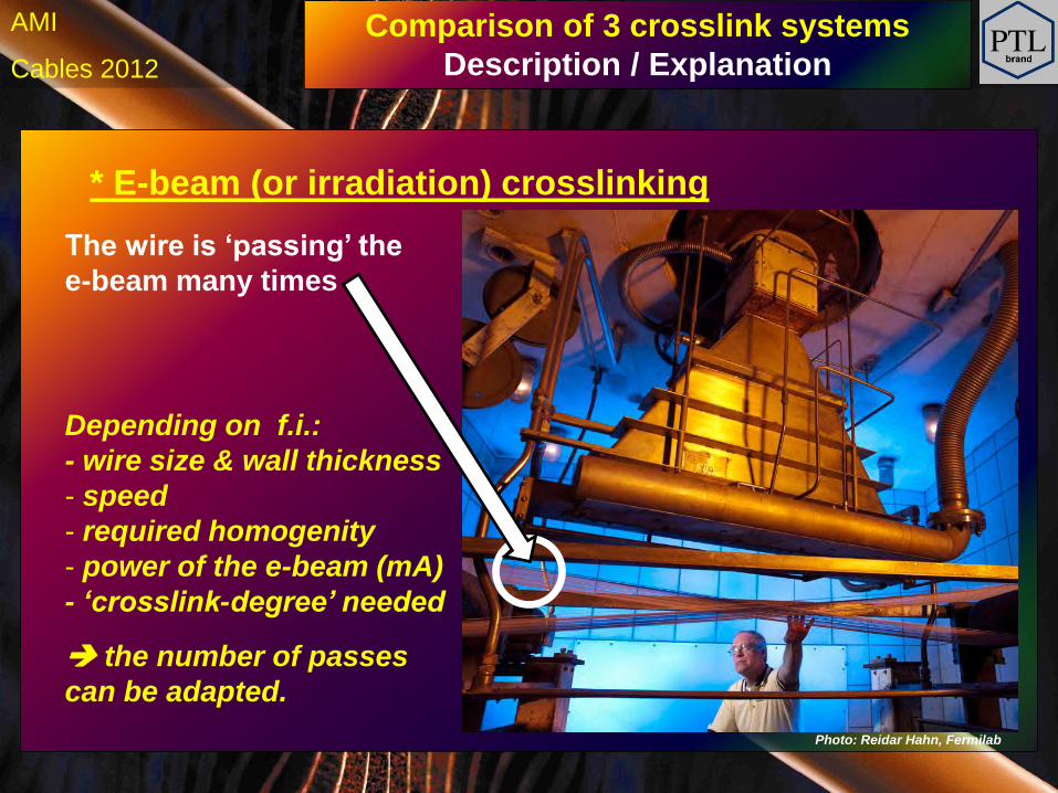
* E-beam (or irradiation) crosslinking
Photo: Reidar Hahn, Fermilab
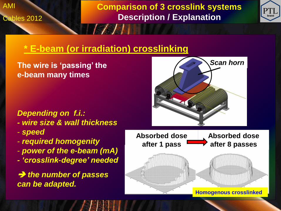
The wire is ‘passing’ the
e-beam many times
Depending on f.i.:
- wire size & wall thickness
- speed
- required homogenity
- power of the e-beam (mA)
- ‘crosslink-degree’ needed
the number of passes
can be adapted.
Comparison of 3 crosslink systems
Description / Explanation
h Cables 2012
AMI
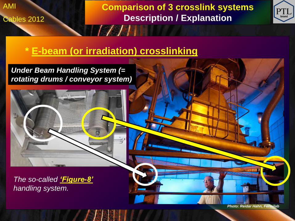
* E-beam (or irradiation) crosslinking
Photo: Reidar Hahn, Fermilab
Comparison of 3 crosslink systems
Description / Explanation
Under Beam Handling System (=
rotating drums / conveyor system)
The so-called ‘Figure-8’
handling system.
h Cables 2012
AMI
* E-beam (or irradiation) crosslinking
The wire is ‘passing’ the
e-beam many times
Depending on f.i.:
- wire size & wall thickness
- speed
- required homogenity
- power of the e-beam (mA)
- ‘crosslink-degree’ needed
the number of passes
can be adapted.
Comparison of 3 crosslink systems
Description / Explanation
Absorbed dose
after 1 pass
Absorbed dose
after 8 passes
Scan horn
Homogenous crosslinked
h Cables 2012
AMI
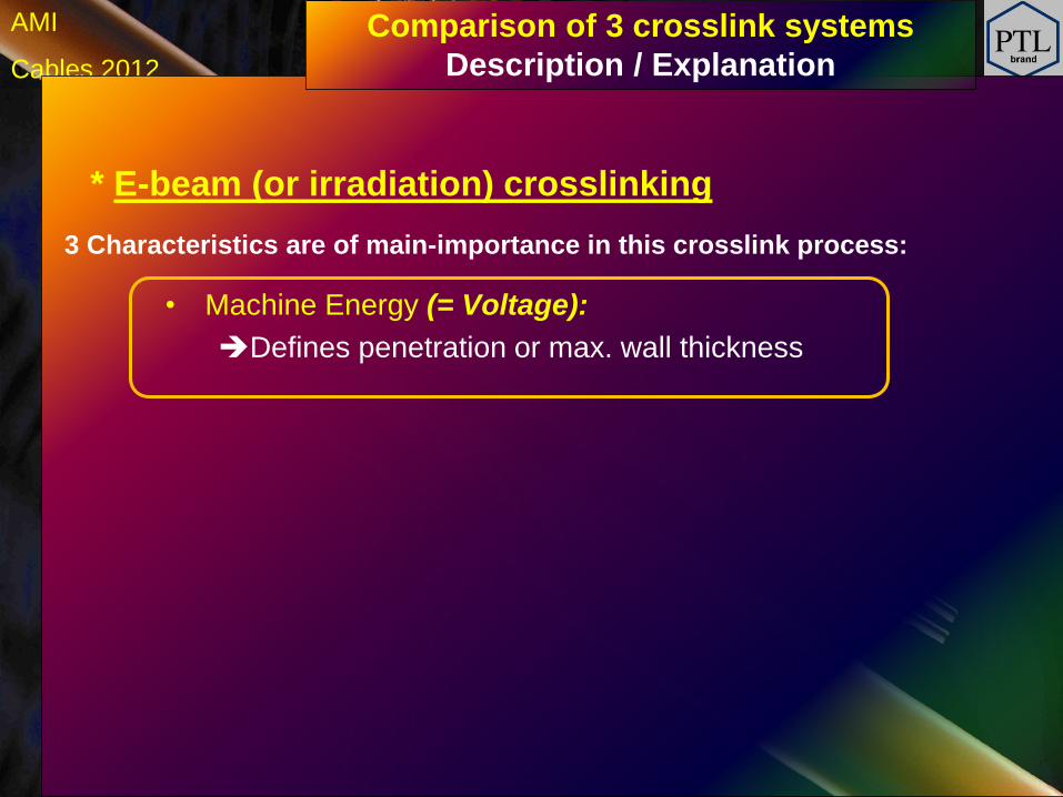
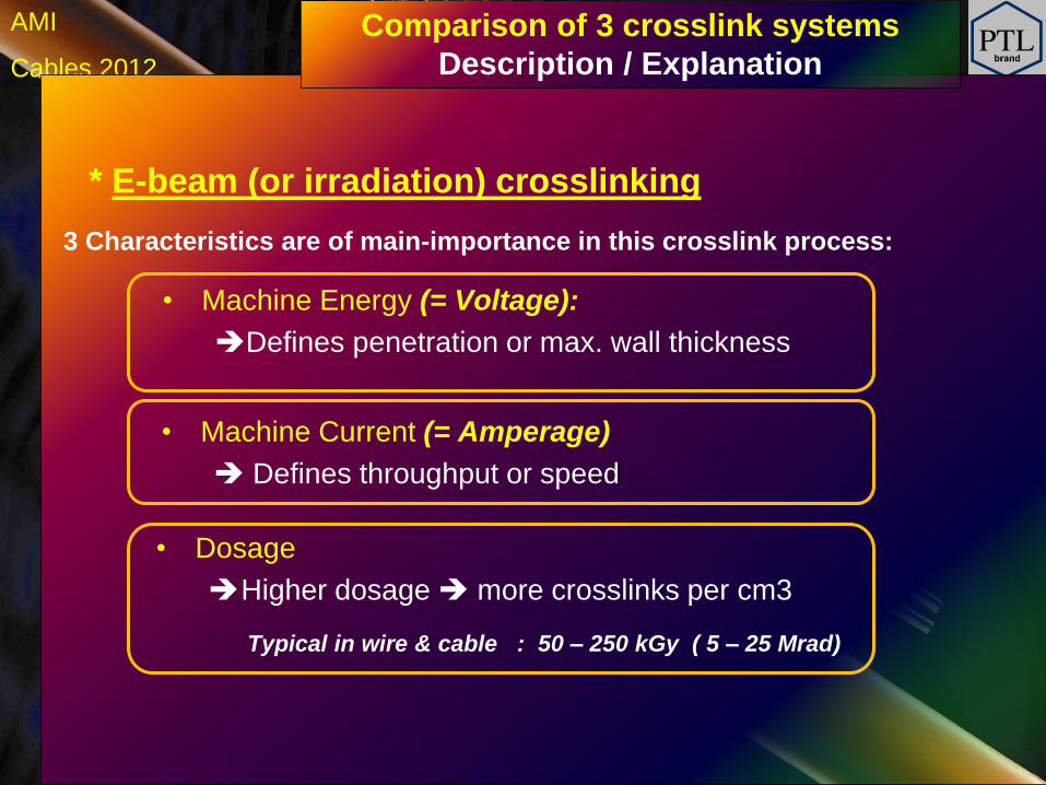
* E-beam (or irradiation) crosslinking
• Machine Energy (= Voltage):
Defines penetration or max. wall thickness
Comparison of 3 crosslink systems
Description / Explanation
3 Characteristics are of main-importance in this crosslink process:
h Cables 2012
AMI
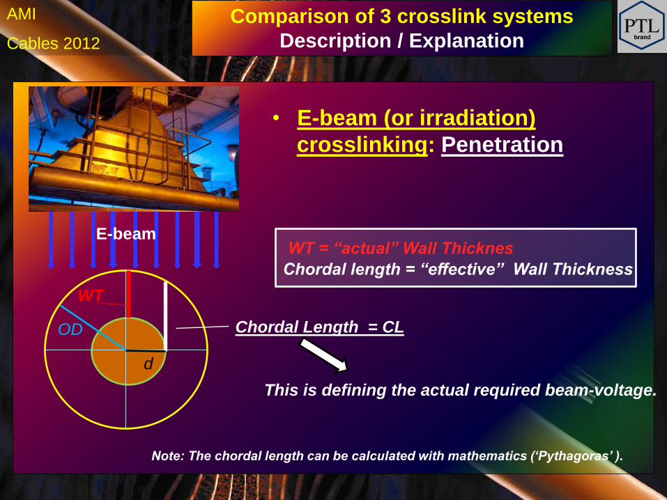
• E-beam (or irradiation)
crosslinking: Penetration
Comparison of 3 crosslink systems
Description / Explanation
WT
This is defining the actual required beam-voltage.
E-beam WT = “actual” Wall Thicknes
Chordal length = “effective” Wall Thickness
d
OD Chordal Length = CL
Note: The chordal length can be calculated with mathematics (‘Pythagoras’ ).
h Cables 2012
AMI
* E-beam (or irradiation) crosslinking
Comparison of 3 crosslink systems
Description / Explanation
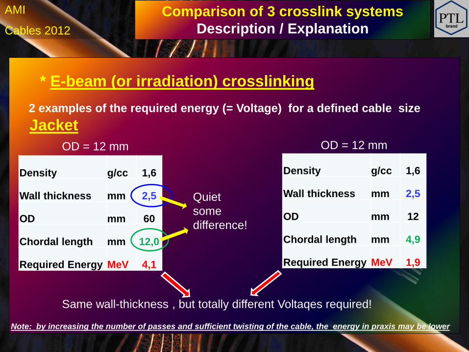
2 examples of the required energy (= Voltage) for a defined cable size
Jacket
Density g/cc 1,6
Wall thickness mm 2,5
OD mm 60
Chordal length mm 12,0
Required Energy MeV 4,1
Quiet
some
difference!
Density g/cc 1,6
Wall thickness mm 2,5
OD mm 12
Chordal length mm 4,9
Required Energy MeV 1,9
OD = 12 mm OD = 12 mm
Same wall-thickness , but totally different Voltaqes required!
Note: by increasing the number of passes and sufficient twisting of the cable, the energy in praxis may be lower
h Cables 2012
AMI
* E-beam (or irradiation) crosslinking
• Machine Energy (= Voltage):
Defines penetration or max. wall thickness
• Dosage
Higher dosage more crosslinks per cm3
Typical in wire & cable : 50 – 250 kGy ( 5 – 25 Mrad)
• Machine Current (= Amperage)
Defines throughput or speed
Comparison of 3 crosslink systems
Description / Explanation
3 Characteristics are of main-importance in this crosslink process:
h Cables 2012
AMI
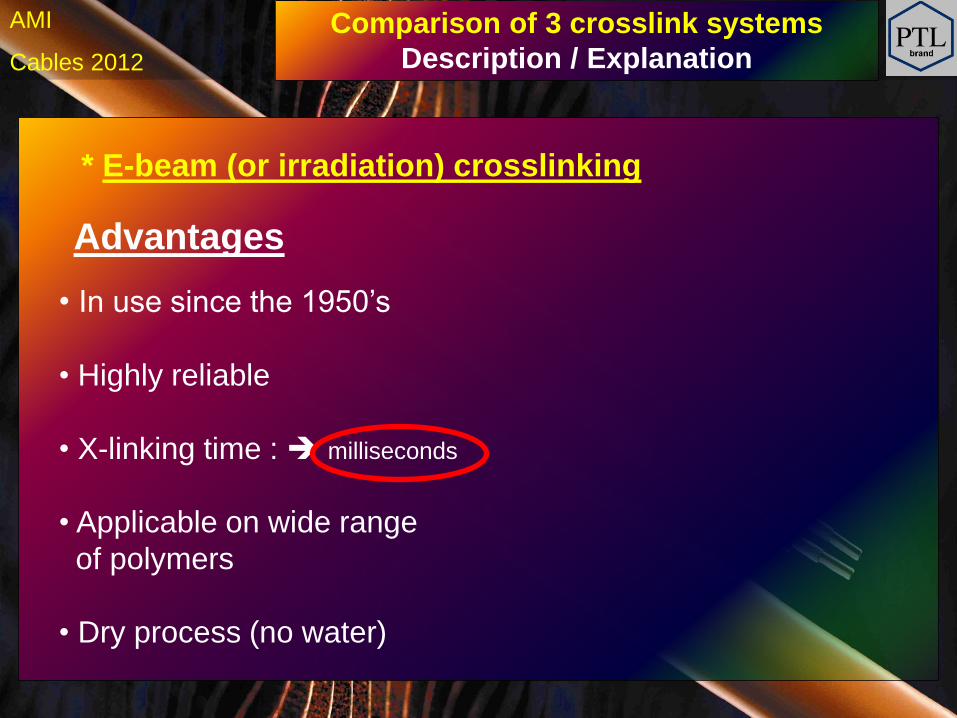
* E-beam (or irradiation) crosslinking
Advantages
• In use since the 1950’s
• Highly reliable
• X-linking time : milliseconds
• Applicable on wide range
of polymers
• Dry process (no water)
Comparison of 3 crosslink systems
Description / Explanation
h Cables 2012
AMI
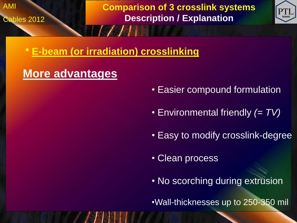
* E-beam (or irradiation) crosslinking
More advantages
• Easier compound formulation
• Environmental friendly (= TV)
• Easy to modify crosslink-degree
• Clean process
• No scorching during extrusion
•Wall-thicknesses up to 250-350 mil
Comparison of 3 crosslink systems
Description / Explanation
h Cables 2012
AMI
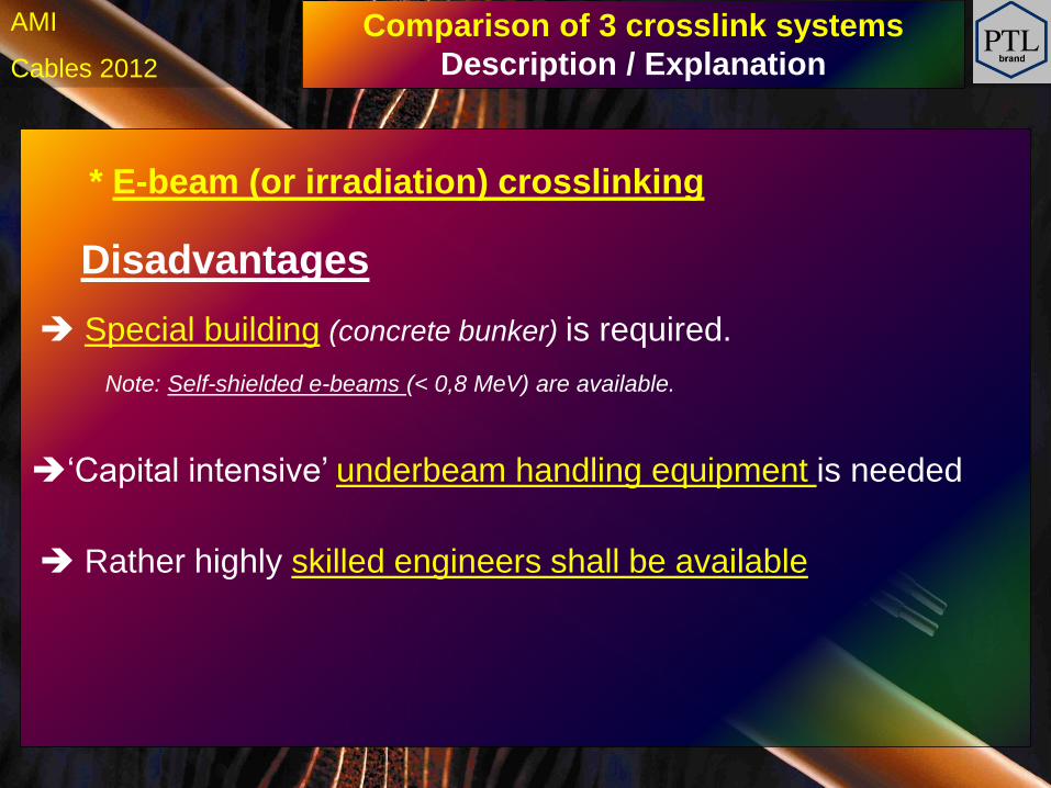
* E-beam (or irradiation) crosslinking
Special building (concrete bunker) is required.
Note: Self-shielded e-beams (< 0,8 MeV) are available.
‘Capital intensive’ underbeam handling equipment is needed
Rather highly skilled engineers shall be available
Comparison of 3 crosslink systems
Description / Explanation
Disadvantages
h Cables 2012
AMI
* E-beam (or irradiation) crosslinking
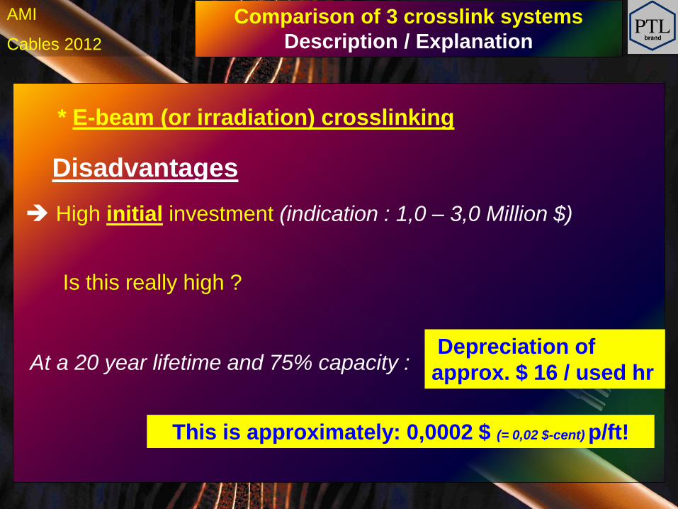
High initial investment (indication : 1,0 – 3,0 Million $)
At a 20 year lifetime and 75% capacity : Depreciation of
approx. $ 16 / used hr
Comparison of 3 crosslink systems
Description / Explanation
Disadvantages
Is this really high ?
This is approximately: 0,0002 $ (= 0,02 $-cent) p/ft!
h Cables 2012
AMI
* E-beam (or irradiation) crosslinking
High initial investment (indication : 1,0 – 3,0 Million $)
At a 20 year lifetime and 75% capacity : Depreciation of
approx. $ 16 / used hr
Comparison of 3 crosslink systems
Description / Explanation
Disadvantages
Is this really high ?
This is approximately: 0,0002 $ (= 0,02 $-cent) p/ft!
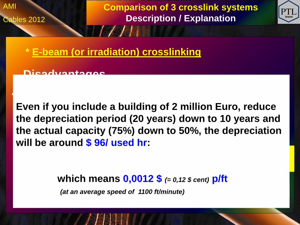
Even if you include a building of 2 million Euro, reduce
the depreciation period (20 years) down to 10 years and
the actual capacity (75%) down to 50%, the depreciation
will be around $ 96/ used hr:
which means 0,0012 $ (= 0,12 $ cent) p/ft
(at an average speed of 1100 ft/minute)
h Cables 2012
AMI
Let’s have a look at the crosslink-costs per kg or lbs
Comparison of 3 crosslink systems
Description / Explanation
h Cables 2012
AMI Comparison of 3 crosslink systems
Description / Explanation
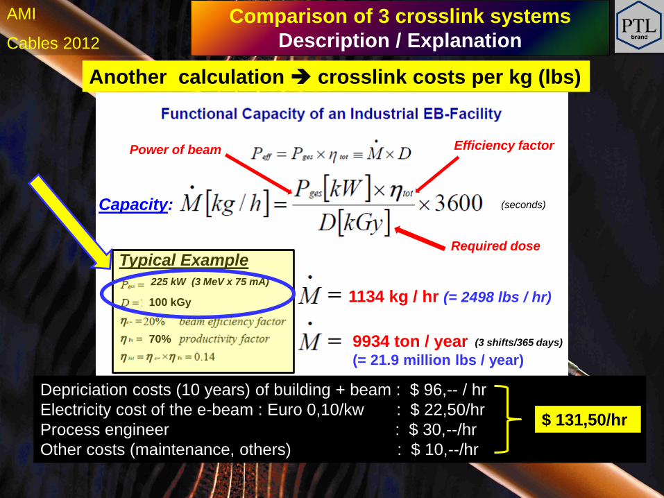
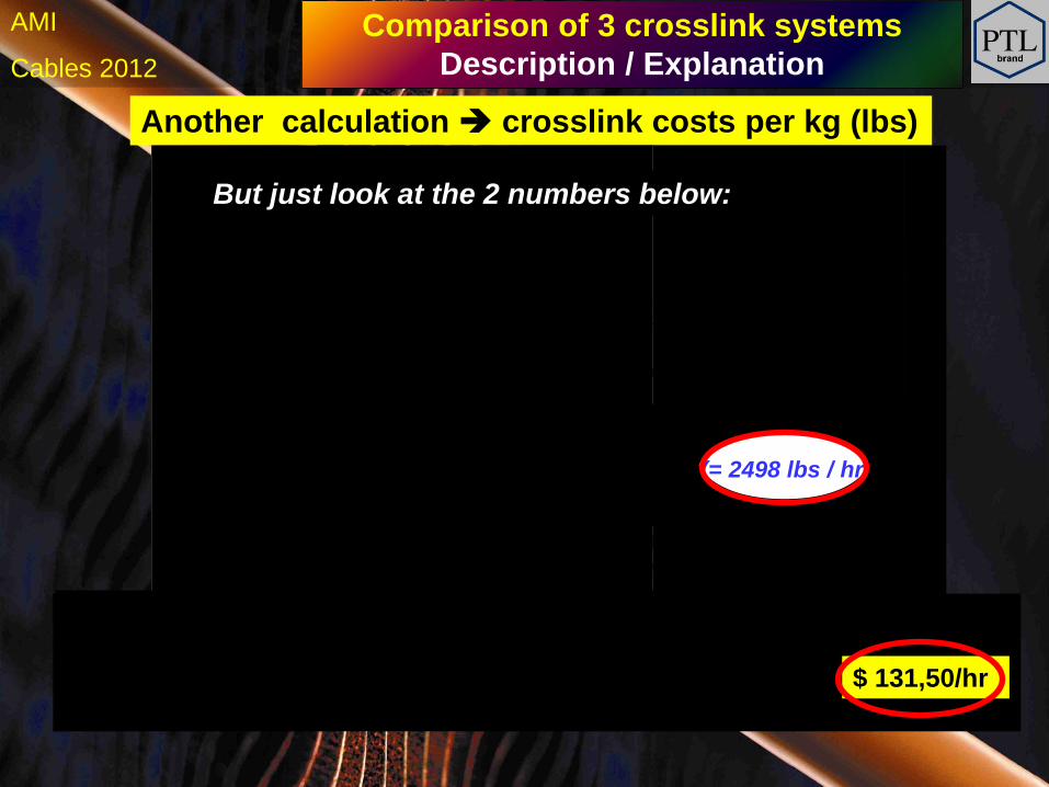
225 kW (3 MeV x 75 mA)
1134 kg / hr (= 2498 lbs / hr)
9934 ton / year (= 21.9 million lbs / year)
70%
Another calculation crosslink costs per kg (lbs)
Depriciation costs (10 years) of building + beam : $ 96,-- / hr
Electricity cost of the e-beam : Euro 0,10/kw : $ 22,50/hr
Process engineer : $ 30,--/hr
Other costs (maintenance, others) : $ 10,--/hr
$ 131,50/hr
Efficiency factor Power of beam
Required dose
Typical Example
(seconds)
(3 shifts/365 days)
100 kGy
Capacity:
h Cables 2012
AMI Comparison of 3 crosslink systems
Description / Explanation
225 kW (3 MeV x 75 mA)
1134 kg / hr (= 2498 lbs / hr)
9934 ton / year (= 21.9 million lbs / year)
70%
Another calculation crosslink costs per kg (lbs)
Depriciation costs (10 years) of building + beam : $ 96,-- / hr
Electricity cost of the e-beam : Euro 0,10/kw : $ 22,50/hr
Process engineer : $ 30,--/hr
Other costs (maintenance, others) : $ 10,--/hr
$ 131,50/hr
Efficiency factor Power of beam
Required dose
Typical Example
(seconds)
(3 shifts/365 days)
100 kGy
Capacity:
But just look at the 2 numbers below:
h Cables 2012
AMI Comparison of 3 crosslink systems
Description / Explanation
225 kW (3 MeV x 75 mA)
70%
Depriciation costs (10 years) of building + beam : $ 96,-- / hr
Electricity cost of the e-beam : Euro 0,10/kw : $ 22,50/hr
Process engineer : $ 30,--/hr
Other costs (maintenance, others) : $ 10,--/hr
$ 131,50/hr
$ 0,05 / lbs
Typical Example
(seconds)
100 kGy
Power of beam Efficiency factor
Required dose
Another calculation crosslink costs per kg (lbs)
1134 kg / hr (= 2498 lbs / hr)
9934 ton / year (= 21.9 million lbs / year)
(3 shifts/365 days)
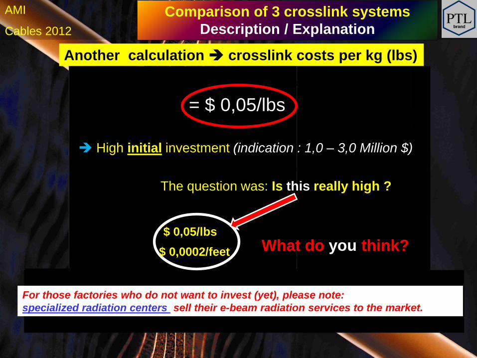
= $ 0,05/lbs
High initial investment (indication : 1,0 – 3,0 Million $)
The question was: Is this really high ?
$ 0,05/lbs
$ 0,0002/feet What do you think?
For those factories who do not want to invest (yet), please note:
specialized radiation centers sell their e-beam radiation services to the market.
h Cables 2012
AMI
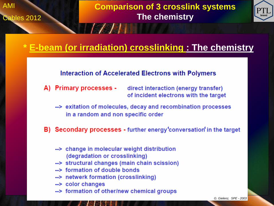
* E-beam (or irradiation) crosslinking : The chemistry
Comparison of 3 crosslink systems
The chemistry
G. Gielenz, SPE - 2003
‘ ‘
h Cables 2012
AMI
Comparison of 3 crosslink systems
Description / Explanation
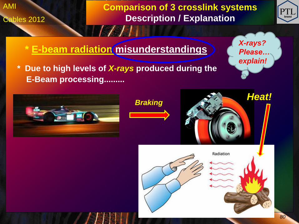
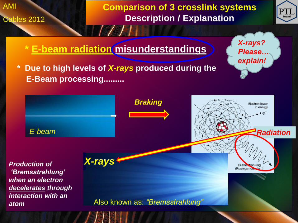
* E-beam radiation misunderstandings
* Due to high levels of X-rays produced during the
E-Beam processing.........
X-rays?
Please…
explain!
Braking Heat!
80

h Cables 2012
AMI
Comparison of 3 crosslink systems
Description / Explanation
* E-beam radiation misunderstandings
* Due to high levels of X-rays produced during the
E-Beam processing.........
X-rays?
Please…
explain!
Braking Heat!
h Cables 2012
AMI
Comparison of 3 crosslink systems
Description / Explanation
* E-beam radiation misunderstandings
* Due to high levels of X-rays produced during the
E-Beam processing.........
X-rays?
Please…
explain!
Braking
X-rays
E-beam Radiation
Also known as: “Bremsstrahlung”
Production of
‘Bremsstrahlung’
when an electron
decelerates through
interaction with an
atom
h Cables 2012
AMI
Picture: By courtesy of IBA (B)
Comparison of 3 crosslink systems
Description / Explanation
Heavy wall
‘bunker’
thick
concrete walls
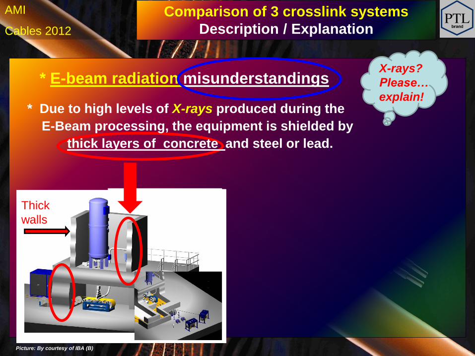
* E-beam radiation misunderstandings
* Due to high levels of X-rays produced during the
E-Beam processing, the equipment is shielded by
thick layers of concrete and steel or lead.
Heavy wall
‘bunker’
thick
concrete walls
X-rays?
Please…
explain!
Thick
walls
h Cables 2012
AMI
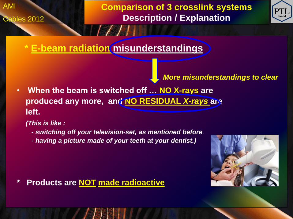
* E-beam radiation misunderstandings
• When the beam is switched off … NO X-rays are
produced any more, and NO RESIDUAL X-rays are
left.
(This is like :
- switching off your television-set, as mentioned before.
- having a picture made of your teeth at your dentist.)
* Products are NOT made radioactive
Comparison of 3 crosslink systems
Description / Explanation
More misunderstandings to clear
h Cables 2012
AMI
Comparison of 3 crosslink systems
Description / Explanation
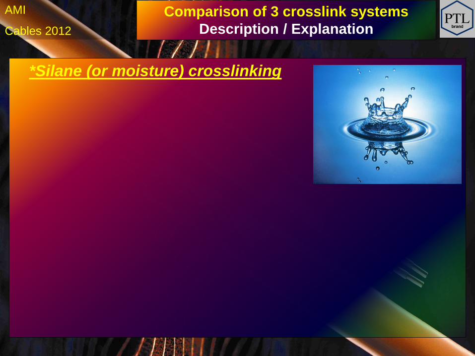
*Silane (or moisture) crosslinking
h Cables 2012
AMI
Comparison of 3 crosslink systems
Description / Explanation
*Silane (or moisture) crosslinking
Extrude and WAIT… that is all!
h Cables 2012
AMI
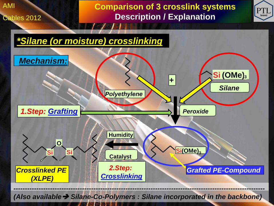
*Silane (or moisture) crosslinking
Polyethylene
Mechanism:
+ Silane
Si (OMe)
Peroxide 1.Step: Grafting
Humidity
Catalyst Si
O
Si
Crosslinked PE
(XLPE)
2.Step:
Crosslinking
Si(OMe)3
Grafted PE-Compound
3
--------------------------------------------------------------------------------------------------------------
(Also available Silane-Co-Polymers : Silane incorporated in the backbone)
Comparison of 3 crosslink systems
Description / Explanation
h Cables 2012
AMI
*Silane (or moisture) crosslinking
Polyethylene
Mechanism:
+ Silane
Si (OMe)
Peroxide 1.Step: Grafting
Humidity
Catalyst Si
O
Si
Crosslinked PE
(XLPE)
2.Step:
Crosslinking
Si(OMe)3
Grafted PE-Compound
3
--------------------------------------------------------------------------------------------------------------
(Also available Silane-Co-Polymers : Silane incorporated in the backbone)
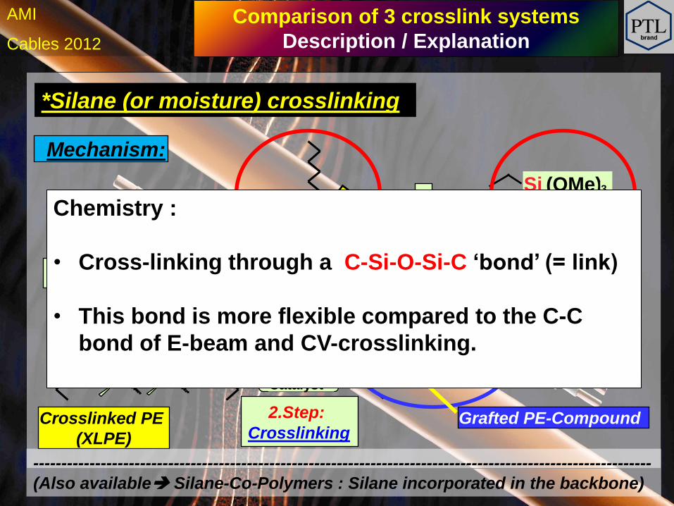
Chemistry :
• Cross-linking through a C-Si-O-Si-C ‘bond’ (= link)
• This bond is more flexible compared to the C-C
bond of E-beam and CV-crosslinking.
Comparison of 3 crosslink systems
Description / Explanation
h Cables 2012
AMI
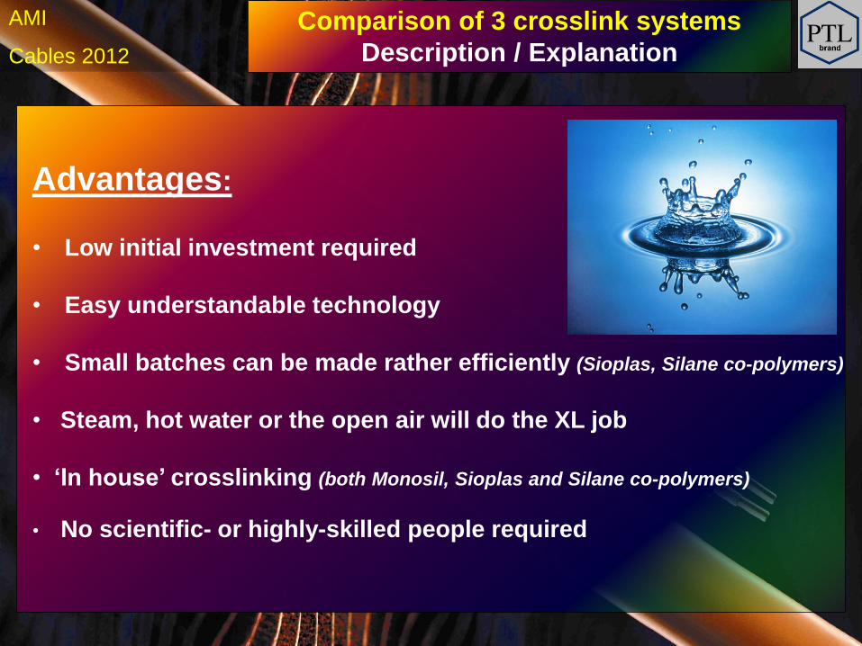
Advantages:
• Low initial investment required
• Easy understandable technology
• Small batches can be made rather efficiently (Sioplas, Silane co-polymers)
• Steam, hot water or the open air will do the XL job
• ‘In house’ crosslinking (both Monosil, Sioplas and Silane co-polymers)
• No scientific- or highly-skilled people required
Comparison of 3 crosslink systems
Description / Explanation
h Cables 2012
AMI
Advantages:
• Low crosslinking costs
Comparison of 3 crosslink systems
Description / Explanation
In ambient environment : $ 0,00 / lbs
In ‘sauna’ environment :
Typically in the range $ 0,02 – 0,06 / lbs, for heating
h Cables 2012
AMI
Disadvantages:
• Higher compound costs (lower output during compounding)
• Complexity in compound design
• Only limited to a small number of polymers (mainly PE – kind )
• Limited storage life of the compounds
• More tight tolerances in extrusion parameters
• Risk of premature crosslinking (due to moisture and design of head and tooling)
Comparison of 3 crosslink systems
Description / Explanation
h Cables 2012
AMI
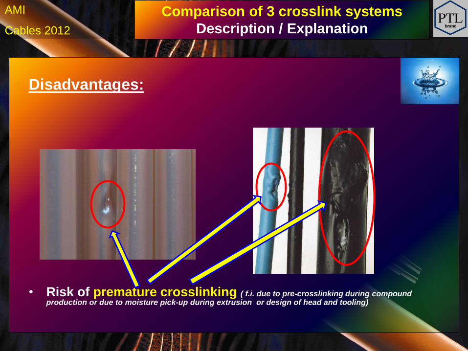
Disadvantages:
• Risk of premature crosslinking ( f.i. due to pre-crosslinking during compound production or due to moisture pick-up during extrusion or design of head and tooling)
Comparison of 3 crosslink systems
Description / Explanation
h Cables 2012
AMI
Comparison of 3 crosslink systems
Description / Explanation
Disadvantages:
• Hardly any influence on crosslink degree (if Sioplas or silane-copolymers outside sources are converted)
• Rather long crosslink times (typically 24 hrs (hot sauna) to several weeks (ambient) Hot-set elongation tests needed)
• If tested before FULL crosslinking has occured, some
unexpected results may show up (think about heat-ageing)
• Decrease of MFI during storage. This may effect
output of extrusion line and surface of extruded product
• Mainly applicable in rather thin wall (< 80 - 120 mil) cables
h Cables 2012
AMI
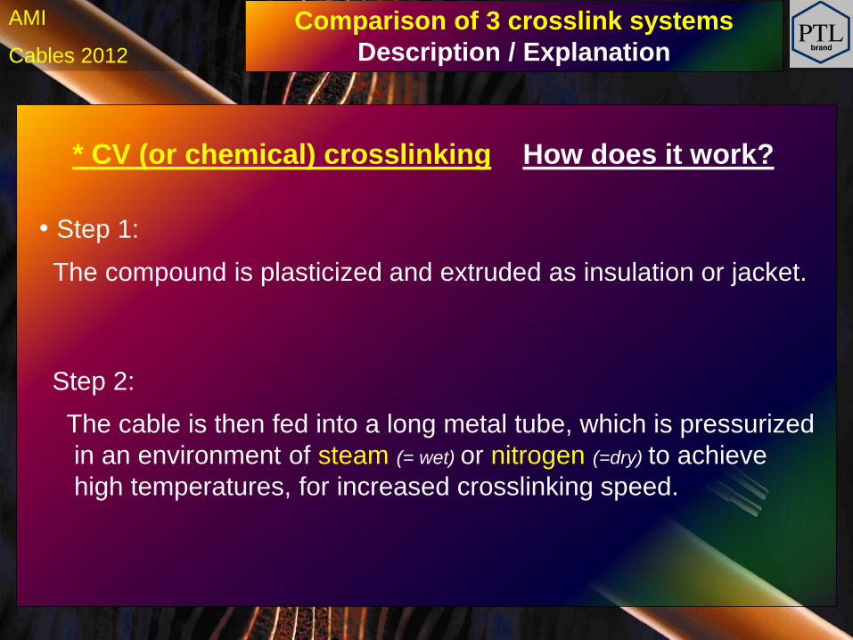
* CV (or chemical) crosslinking How does it work?
• Step 1:
The compound is plasticized and extruded as insulation or jacket.
Step 2:
The cable is then fed into a long metal tube, which is pressurized
in an environment of steam (= wet) or nitrogen (=dry) to achieve
high temperatures, for increased crosslinking speed.
Comparison of 3 crosslink systems
Description / Explanation
h Cables 2012
AMI
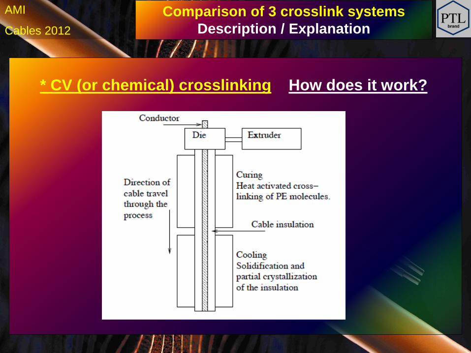
* CV (or chemical) crosslinking How does it work?
Comparison of 3 crosslink systems
Description / Explanation
h Cables 2012
AMI
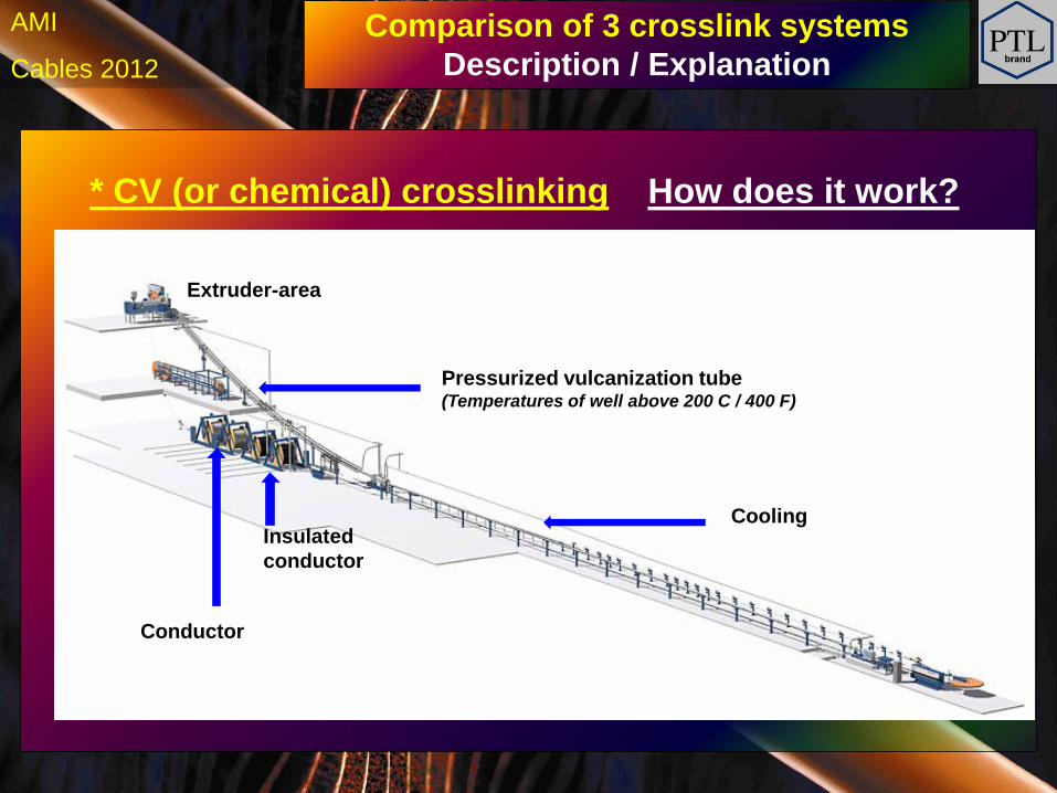
* CV (or chemical) crosslinking How does it work?
Extruder-area
Pressurized vulcanization tube (Temperatures of well above 200 C / 400 F)
Cooling Insulated
conductor
Conductor
Comparison of 3 crosslink systems
Description / Explanation
h Cables 2012
AMI
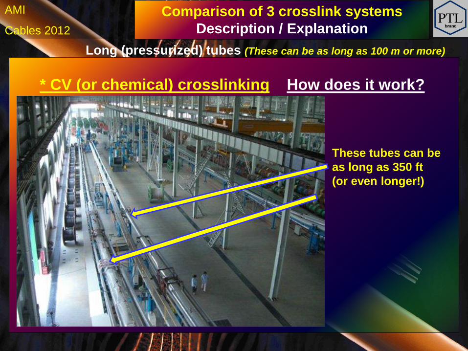
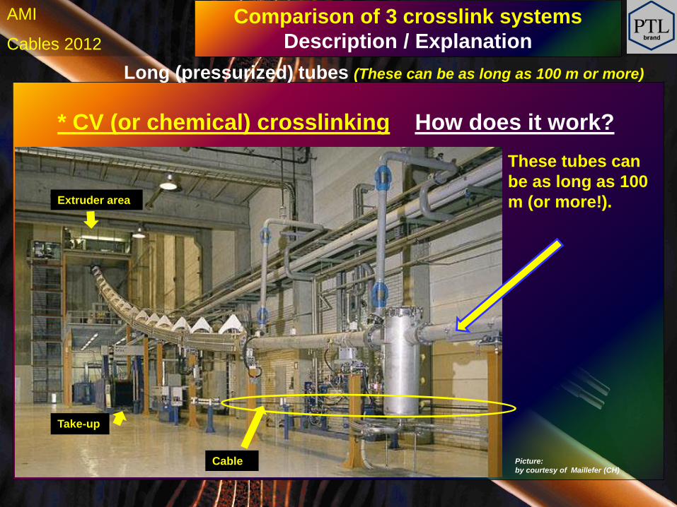
* CV (or chemical) crosslinking
Long (pressurized) tubes (These can be as long as 100 m or more)
How does it work?
These tubes can be
as long as 350 ft
(or even longer!)
Comparison of 3 crosslink systems
Description / Explanation
h Cables 2012
AMI
* CV (or chemical) crosslinking
Long (pressurized) tubes (These can be as long as 100 m or more)
How does it work?
These tubes can
be as long as 100
m (or more!). Extruder area
Picture:
by courtesy of Maillefer (CH)
Comparison of 3 crosslink systems
Description / Explanation
Take-up
Cable
h Cables 2012
AMI
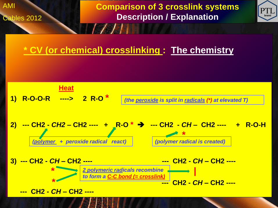
Heat
1) R-O-O-R ----> 2 R-O *
2) --- CH2 - CH2 – CH2 ---- + R-O * --- CH2 - CH – CH2 ---- + R-O-H
*
3) --- CH2 - CH – CH2 ---- --- CH2 - CH – CH2 ----
* |
* --- CH2 - CH – CH2 ----
--- CH2 - CH – CH2 ----
2 polymeric radicals recombine
to form a C-C bond (= crosslink)
(the peroxide is split in radicals (*) at elevated T)
(polymer + peroxide radical react) (polymer radical is created)
* CV (or chemical) crosslinking : The chemistry
Comparison of 3 crosslink systems
Description / Explanation
h Cables 2012
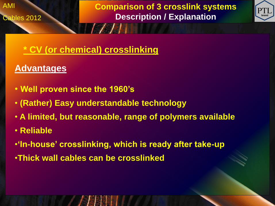
AMI
• Well proven since the 1960’s
• (Rather) Easy understandable technology
• A limited, but reasonable, range of polymers available
• Reliable
•‘In-house’ crosslinking, which is ready after take-up
•Thick wall cables can be crosslinked
Advantages
* CV (or chemical) crosslinking
Comparison of 3 crosslink systems
Description / Explanation
h Cables 2012
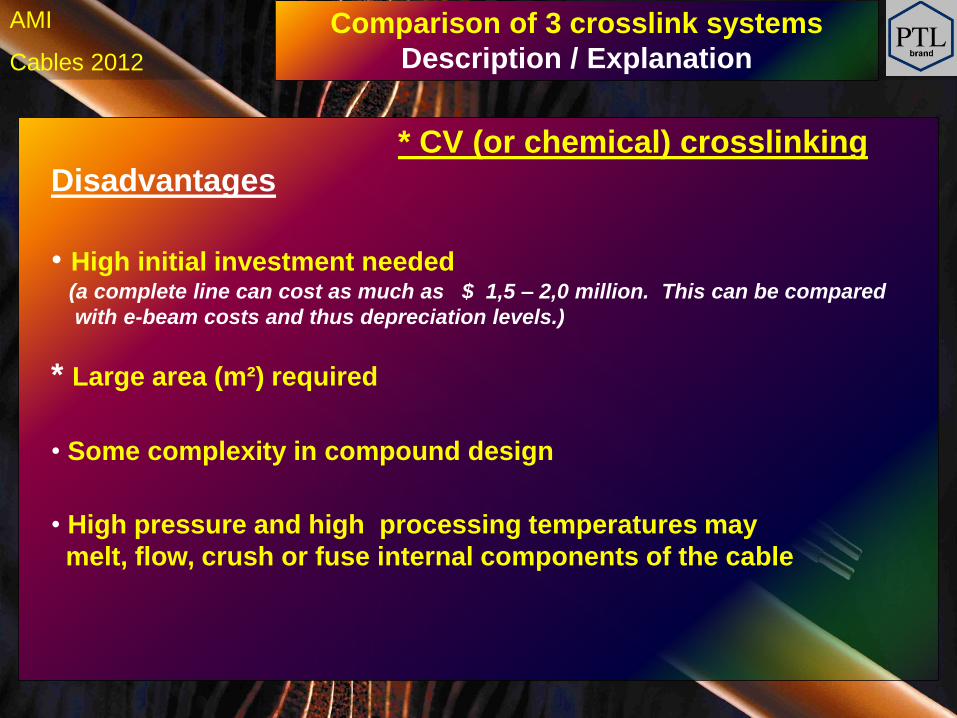
AMI
Disadvantages
• High initial investment needed (a complete line can cost as much as $ 1,5 – 2,0 million. This can be compared
with e-beam costs and thus depreciation levels.)
* Large area (m²) required
• Some complexity in compound design
• High pressure and high processing temperatures may
melt, flow, crush or fuse internal components of the cable
* CV (or chemical) crosslinking
Comparison of 3 crosslink systems
Description / Explanation
h Cables 2012
AMI
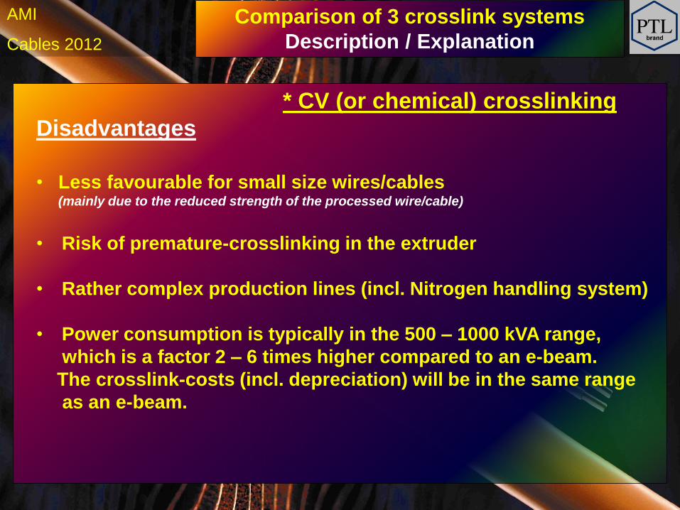
Disadvantages
• Less favourable for small size wires/cables (mainly due to the reduced strength of the processed wire/cable)
• Risk of premature-crosslinking in the extruder
• Rather complex production lines (incl. Nitrogen handling system)
• Power consumption is typically in the 500 – 1000 kVA range,
which is a factor 2 – 6 times higher compared to an e-beam.
The crosslink-costs (incl. depreciation) will be in the same range
as an e-beam.
* CV (or chemical) crosslinking
Comparison of 3 crosslink systems
Description / Explanation
h Cables 2012
AMI
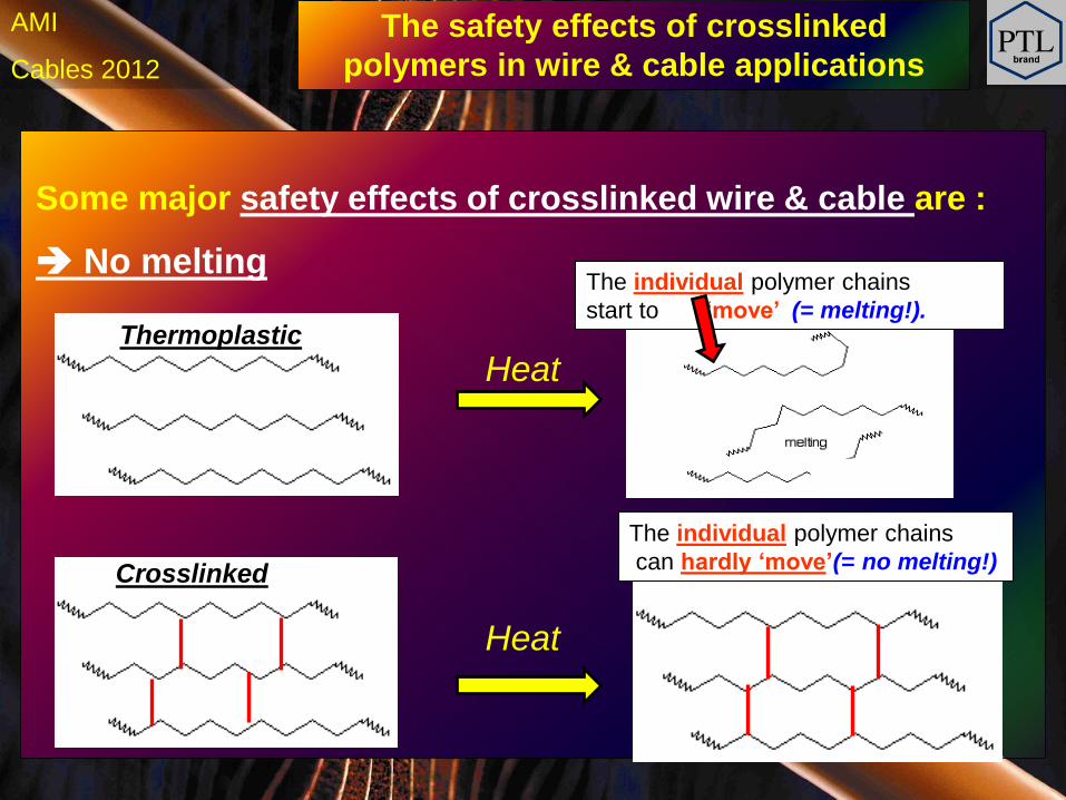
\
Heat
Heat
Thermoplastic
Crosslinked
The individual polymer chains
start to ‘move’’ (= melting!).
The individual polymer chains
can hardly ‘move’(= no melting!)
Some major safety effects of crosslinked wire & cable are :
No melting
The safety effects of crosslinked
polymers in wire & cable applications
h Cables 2012
AMI
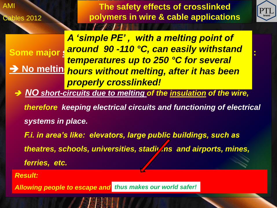
Some major safety effects of crosslinked wire & cable are :
No melting
NO short-circuits due to melting of the insulation of the wire,
therefore keeping electrical circuits and functioning of electrical
systems in place.
F.i. in area’s like: elevators, large public buildings, such as
theatres, schools, universities, stadiums and airports, mines,
ferries, etc.
A ‘simple PE’ , with a melting point of
around 90 -110 °C, can easily withstand
temperatures up to 250 °C for several
hours without melting, after it has been
properly crosslinked!
Result:
Allowing people to escape and thus makes our world safer!
The safety effects of crosslinked
polymers in wire & cable applications
h Cables 2012
AMI
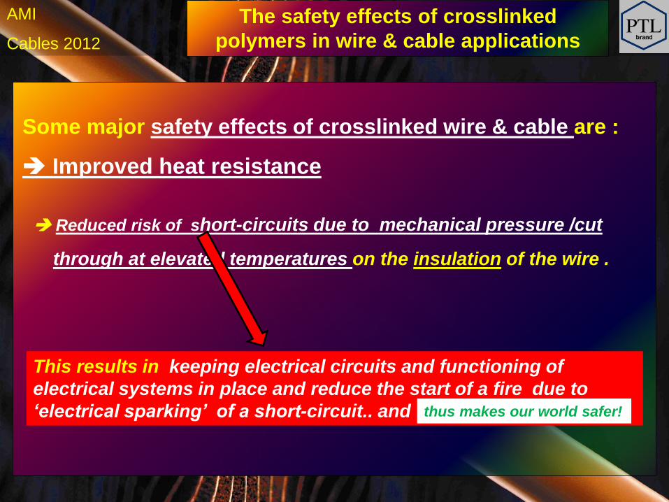
Some major safety effects of crosslinked wire & cable are :
Improved heat resistance
Reduced risk of short-circuits due to mechanical pressure /cut
through at elevated temperatures on the insulation of the wire .
This results in keeping electrical circuits and functioning of
electrical systems in place and reduce the start of a fire due to
‘electrical sparking’ of a short-circuit.. and
thus makes our world safer!
The safety effects of crosslinked
polymers in wire & cable applications
h Cables 2012
AMI
Some major safety effects of crosslinked wire & cable are :
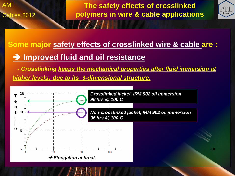
Improved fluid and oil resistance
- Crosslinking keeps the mechanical properties after fluid immersion at
higher levels, due to its 3-dimensional structure,
Elongation at break
T
e
n
s
i
l
e
10
10
5
15
Non-crosslinked jacket, IRM 902 oil immersion
96 hrs @ 100 C
Crosslinked jacket, IRM 902 oil immersion
96 hrs @ 100 C
The safety effects of crosslinked
polymers in wire & cable applications
h Cables 2012
AMI
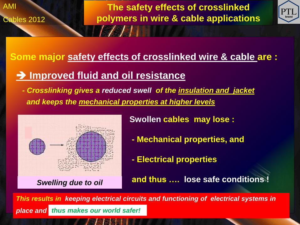
Some major safety effects of crosslinked wire & cable are :
Improved fluid and oil resistance
- Crosslinking gives a reduced swell of the insulation and jacket
a and keeps the mechanical properties at higher levels
Swelling due to oil
Swollen cables may lose :
- Mechanical properties, and
- Electrical properties
and thus …. lose safe conditions !
This results in keeping electrical circuits and functioning of electrical systems in
place and
thus makes our world safer!
The safety effects of crosslinked
polymers in wire & cable applications

h Cables 2012
AMI
Some major safety effects of crosslinked wire & cable are :
Improved stress crack resistance
Cracks after
heat shock @ 136°C
Non-crosslinked insulation Crosslinked insulation
NO cracks after
heat shock @ 250°C
This results in keeping electrical circuits and functioning of electrical systems in
place and
thus makes our world safer!
Pictures by courtesy of Habia
The safety effects of crosslinked
polymers in wire & cable applications
h Cables 2012
AMI
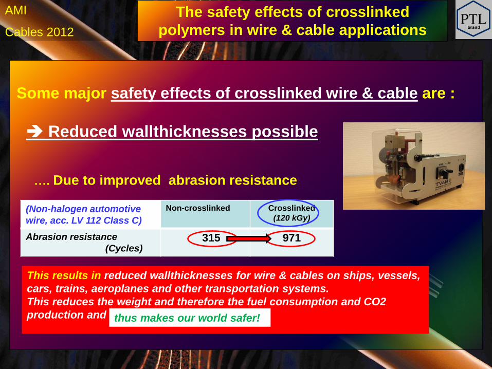
Reduced wallthicknesses possible
Some major safety effects of crosslinked wire & cable are :
…. Due to improved abrasion resistance
(Non-halogen automotive
wire, acc. LV 112 Class C)
Non-crosslinked Crosslinked
(120 kGy)
Abrasion resistance
(Cycles) 315 971
This results in reduced wallthicknesses for wire & cables on ships, vessels,
cars, trains, aeroplanes and other transportation systems.
This reduces the weight and therefore the fuel consumption and CO2
production and
thus makes our world safer!
The safety effects of crosslinked
polymers in wire & cable applications
h Cables 2012
AMI
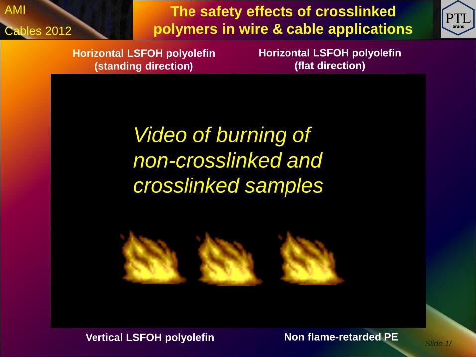
Slide 1/
Non flame-retarded PE
Horizontal LSFOH polyolefin
(standing direction)
Vertical LSFOH polyolefin
Horizontal LSFOH polyolefin
(flat direction)
Video of burning of
non-crosslinked and
crosslinked samples
The safety effects of crosslinked
polymers in wire & cable applications
h Cables 2012
AMI Crosslinking and the safety effects of
crosslinked wire & cables
Some major safety effects of crosslinked wire & cable are :
Reduced or no dripping during burning
This results in reduced flame-spread
thus makes our world safer!
h Cables 2012
AMI
Increaing
Radiation dose
Gelc
on
ten
t
High
Low
High
Low
Low High
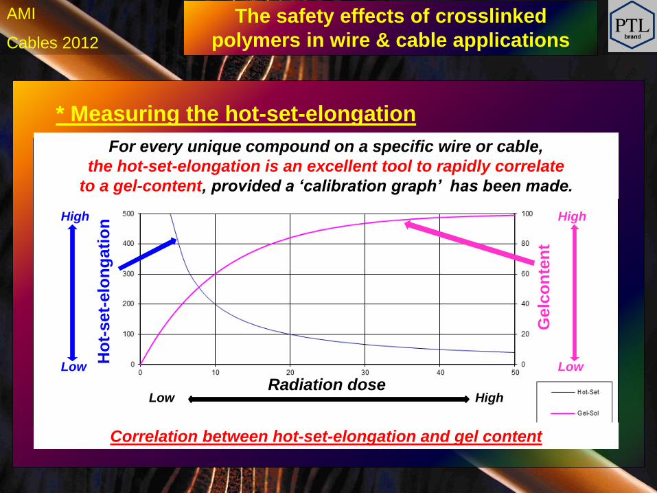
Correlation between hot-set-elongation and gel content
For every unique compound on a specific wire or cable,
the hot-set-elongation is an excellent tool to rapidly correlate
to a gel-content, provided a ‘calibration graph’ has been made.
Ho
t-set-
elo
ng
ati
on
* Measuring the hot-set-elongation
The safety effects of crosslinked
polymers in wire & cable applications
h Cables 2012
AMI
Increaing
Radiation dose
Gelc
on
ten
t
High
Low
High
Low
Low High
Correlation between hot-set-elongation and gel content
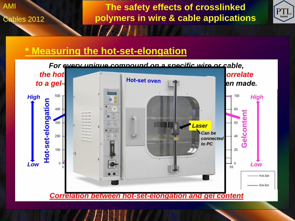
For every unique compound on a specific wire or cable,
the hot-set-elongation is an excellent tool to rapidly correlate
to a gel-content, provided a ‘calibration graph’ has been made.
Ho
t-set-
elo
ng
ati
on
* Measuring the hot-set-elongation
Laser
Can be
connected
to PC
The safety effects of crosslinked
polymers in wire & cable applications
h Cables 2012
AMI
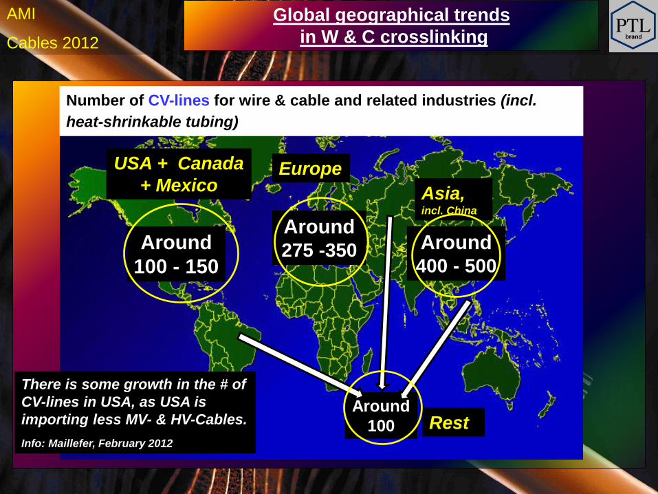
USA + Canada
+ Mexico
Around
100 - 150
Around 275 -350 Around
400 - 500
Europe
Rest Around
100
Number of CV-lines for wire & cable and related industries (incl.
heat-shrinkable tubing)
Asia, incl. China
Global geographical trends
in W & C crosslinking
There is some growth in the # of
CV-lines in USA, as USA is
importing less MV- & HV-Cables.
Info: Maillefer, February 2012
h Cables 2012
AMI
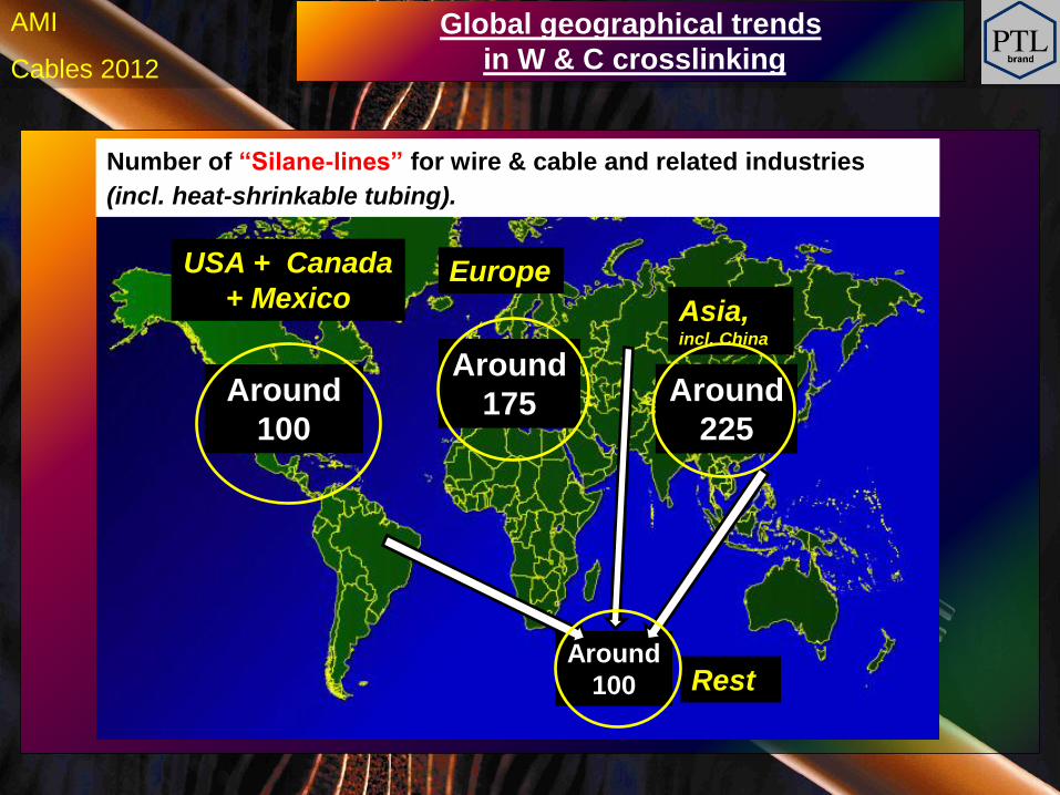
USA + Canada
+ Mexico
Around
100
Around
175 Around
225
Europe
Rest Around
100
Number of “Silane-lines” for wire & cable and related industries
(incl. heat-shrinkable tubing).
Asia, incl. China
Global geographical trends
in W & C crosslinking
h Cables 2012
AMI
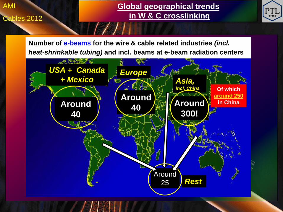
USA + Canada
+ Mexico
Around
40
Number of e-beams for the wire & cable related industries (incl.
heat-shrinkable tubing) and incl. beams at e-beam radiation centers
Around
40
Europe Asia, incl. China
Around
300!
Global geographical trends
in W & C crosslinking
Of which
around 250
in China
Rest Around
25
h Cables 2012
AMI
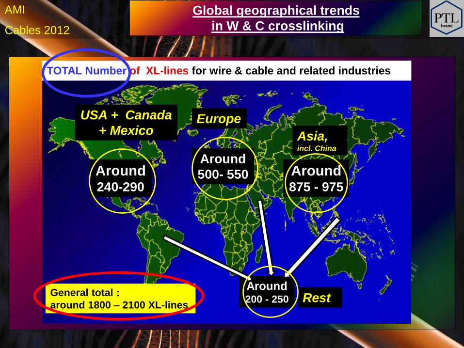
USA + Canada
+ Mexico
Around 240-290
Around
500- 550
Asia, incl. China
Around 875 - 975
Europe
Rest Around 200 - 250
TOTAL Number of XL-lines for wire & cable and related industries
Global geographical trends
in W & C crosslinking
General total :
around 1800 – 2100 XL-lines
h Cables 2012
AMI
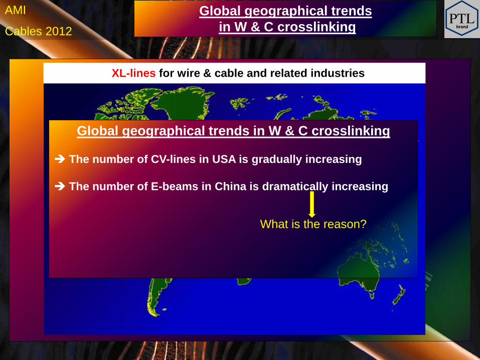
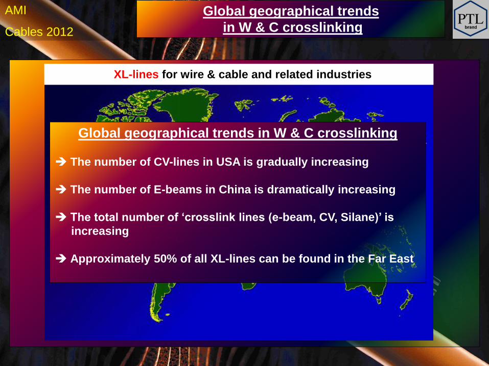
XL-lines for wire & cable and related industries
Global geographical trends
in W & C crosslinking
Global geographical trends in W & C crosslinking
The number of CV-lines in USA is gradually increasing
The number of E-beams in China is dramatically increasing
What is the reason?
h Cables 2012
AMI
Around 200
Around
300- 350
Asia, incl. China
Around 450 - 500
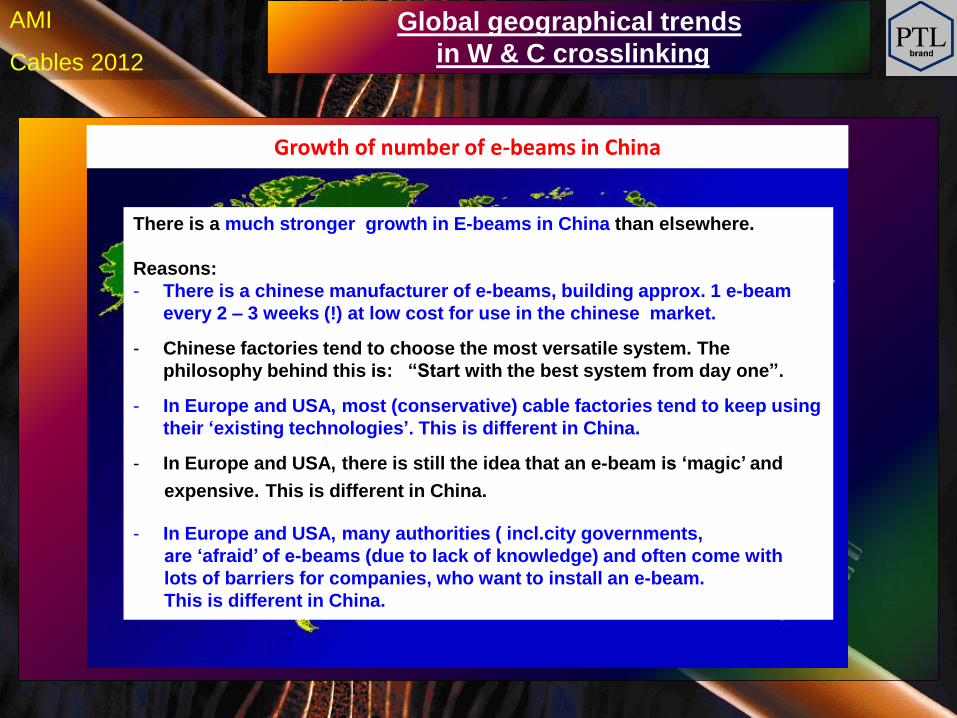
Growth of number of e-beams in China
Global geographical trends
in W & C crosslinking
There is a much stronger growth in E-beams in China than elsewhere.
Reasons:
- There is a chinese manufacturer of e-beams, building approx. 1 e-beam
every 2 – 3 weeks (!) at low cost for use in the chinese market.
- Chinese factories tend to choose the most versatile system. The
philosophy behind this is: “Start with the best system from day one”.
- In Europe and USA, most (conservative) cable factories tend to keep using
their ‘existing technologies’. This is different in China.
- In Europe and USA, there is still the idea that an e-beam is ‘magic’ and
expensive. This is different in China.
- In Europe and USA, many authorities ( incl.city governments,
are ‘afraid’ of e-beams (due to lack of knowledge) and often come with
lots of barriers for companies, who want to install an e-beam.
This is different in China.
h Cables 2012
AMI
XL-lines for wire & cable and related industries
Global geographical trends
in W & C crosslinking
Global geographical trends in W & C crosslinking
The number of CV-lines in USA is gradually increasing
The number of E-beams in China is dramatically increasing
The total number of ‘crosslink lines (e-beam, CV, Silane)’ is
increasing
Approximately 50% of all XL-lines can be found in the Far East
h Cables 2012
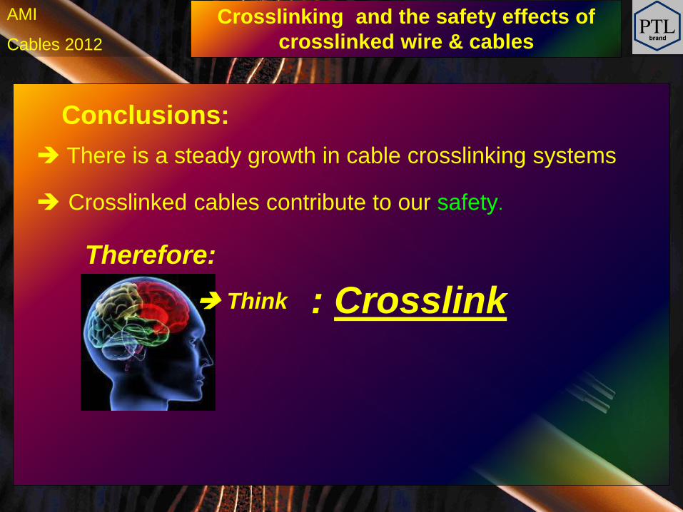
AMI Crosslinking and the safety effects of
crosslinked wire & cables
Conclusions:
Crosslinked cables contribute to our safety.
There is a steady growth in cable crosslinking systems
Therefore:
Think : Crosslink


![SMART” POLYMERIC BINDERS FOR ENERGETIC...butyl acrylate-methyl acrilate copolymers was compared. It was observed that the crosslinked polymers showed the best adhesion [10]. Macais](https://img.pdfslide.us/doc/110x75/60e2def449201911af79000b/smarta-polymeric-binders-for-energetic-butyl-acrylate-methyl-acrilate-copolymers.jpg)