Embed Size (px)
Citation preview
THE ROOM CLEANING ROBOT
Group 12
Group Members:
Daniel Norris, Daniel Mansfield, Luke Nibbelink, Brett Stone
Colorado State University
Mechanical Engineering
MECH 307 - Introduction to Mechatronics
December 9, 2016
1 | P a g e
Colorado State University
Dept. of Mechanical Engineering
MECH 307
Group 12
Table of Contents 1 Design Summary ..................................................................................................................... 2
1.1 Navigation of the Robot ................................................................................................... 3
1.2 Picking Up An Object ...................................................................................................... 3
1.2.1 The Universal Gripper .............................................................................................. 3
2 System Details ........................................................................................................................ 4
2.1 User Input and Display ..................................................................................................... 5
2.2 Logic, Processing, and Control ........................................................................................ 6
2.3 Mechanisms ...................................................................................................................... 9
2.4 Automatic Sensors............................................................................................................ 9
2.5 Audio .............................................................................................................................. 10
3 Design Evaluation ................................................................................................................. 15
4 Partial Parts List .................................................................................................................... 17
5 Lessons Learned.................................................................................................................... 18
6 References ............................................................................................................................. 19
Appendices
Appendix A. Program Code Used .............................................................................................. A-1
2 | P a g e
Colorado State University
Dept. of Mechanical Engineering
MECH 307
Group 12
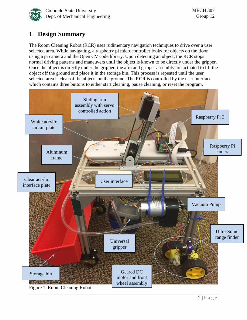
1 Design Summary
The Room Cleaning Robot (RCR) uses rudimentary navigation techniques to drive over a user
selected area. While navigating, a raspberry pi microcontroller looks for objects on the floor
using a pi camera and the Open CV code library. Upon detecting an object, the RCR stops
normal driving patterns and maneuvers until the object is known to be directly under the gripper.
Once the object is directly under the gripper, the arm and gripper assembly are actuated to lift the
object off the ground and place it in the storage bin. This process is repeated until the user
selected area is clear of the objects on the ground. The RCR is controlled by the user interface
which contains three buttons to either start cleaning, pause cleaning, or reset the program.
Figure 1. Room Cleaning Robot
Geared DC
motor and front
wheel assembly
Vacuum Pump
Sliding arm
assembly with servo
controlled action
Universal
gripper
User interface
Aluminum
frame
Raspberry Pi 3
Ultra-Sonic
range finder
Storage bin
White acrylic
circuit plate
Clear acrylic
interface plate
Raspberry Pi
camera
3 | P a g e
Colorado State University
Dept. of Mechanical Engineering
MECH 307
Group 12
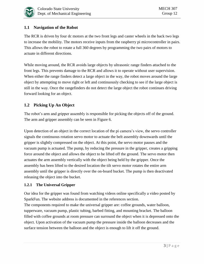
1.1 Navigation of the Robot
The RCR is driven by four dc motors at the two front legs and caster wheels in the back two legs
to increase the mobility. The motors receive inputs from the raspberry pi microcontroller in pairs.
This allows the robot to rotate a full 360 degrees by programming the two pairs of motors to
actuate in different directions.
While moving around, the RCR avoids large objects by ultrasonic range finders attached to the
front legs. This prevents damage to the RCR and allows it to operate without user supervision.
When either the range finders detect a large object in the way, the robot moves around the large
object by attempting to move right or left and continuously checking to see if the large object is
still in the way. Once the rangefinders do not detect the large object the robot continues driving
forward looking for an object.
1.2 Picking Up An Object
The robot’s arm and gripper assembly is responsible for picking the objects off of the ground.
The arm and gripper assembly can be seen in Figure 6.
Upon detection of an object in the correct location of the pi camera’s view, the servo controller
signals the continuous rotation servo motor to actuate the belt assembly downwards until the
gripper is slightly compressed on the object. At this point, the servo motor pauses and the
vacuum pump is actuated. The pump, by reducing the pressure in the gripper, creates a gripping
force around the object and allows the object to be lifted off the ground. The servo motor then
actuates the arm assembly vertically with the object being held by the gripper. Once the
assembly has been lifted to the desired location the tilt servo motor rotates the entire arm
assembly until the gripper is directly over the on-board bucket. The pump is then deactivated
releasing the object into the bucket.
1.2.1 The Universal Gripper
Our idea for the gripper was found from watching videos online specifically a video posted by
SparkFun. The website address is documented in the references section.
The components required to make the universal gripper are: coffee grounds, water balloon,
tupperware, vacuum pump, plastic tubing, barbed fitting, and mounting bracket. The balloon
filled with coffee grounds at room pressure can surround the object when it is depressed onto the
object. Upon activation of the vacuum pump the pressure inside the balloon decreases and the
surface tension between the balloon and the object is enough to lift it off the ground.
4 | P a g e
Colorado State University
Dept. of Mechanical Engineering
MECH 307
Group 12
2 System Details
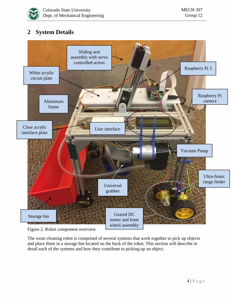
Figure 2. Robot component overview
The room cleaning robot is comprised of several systems that work together to pick up objects
and place them in a storage bin located on the back of the robot. This section will describe in
detail each of the systems and how they contribute to picking up an object.
Geared DC
motor and front
wheel assembly
Vacuum Pump
Sliding arm
assembly with servo
controlled action
Universal
grabber
User interface
Aluminum
frame
Raspberry Pi 3
Ultra-Sonic
range finder
Storage bin
White acrylic
circuit plate
Clear acrylic
interface plate
Raspberry Pi
camera
5 | P a g e
Colorado State University
Dept. of Mechanical Engineering
MECH 307
Group 12
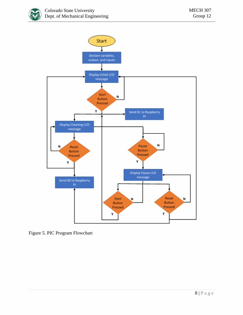
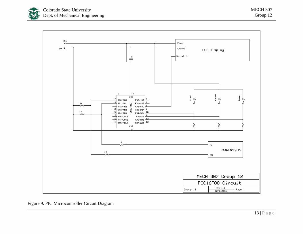
2.1 User Input and Display
Operating the room cleaning robot begins with the user input and the LCD display. The User
interface is labeled in Figure 2. When power is connected to the robot and it is ready to run the
LCD screen will prompt the user to place the robot and press the “Start” button to begin
cleaning. Once pressed, the screen changes to display a message indicating that the user can
either pause, or reset the device. The LCD screen and user input is controlled by a PIC16F88
microcontroller. The PIC displays text on the LCD screen by means of a serial interface, and
sends a two bit binary code to the Raspberry Pi 3 to indicate what state the user has selected. The
5 volt signals from the PIC are reduced with voltage dividers to avoid damaging the 3.3 volt
logic on the Raspberry Pi.
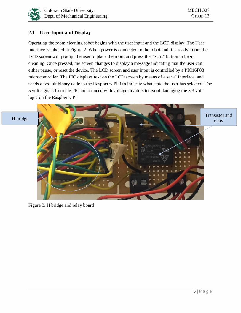
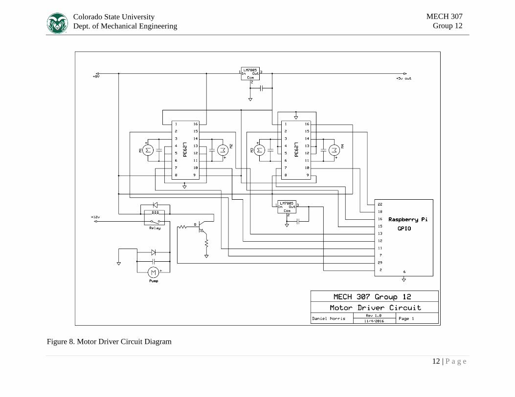
Figure 3. H bridge and relay board
Transistor and
relay H bridge
6 | P a g e
Colorado State University
Dept. of Mechanical Engineering
MECH 307
Group 12
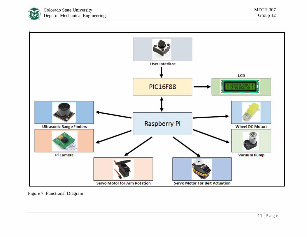
2.2 Logic, Processing, and Control
When the user presses the start button, the Raspberry Pi begins to capture and process images of
the floor while the device drives forward. The program on the Raspberry Pi uses tools from the
OpenCV code library to identify any objects in the image that stand out from the background,
and are sufficiently large. A short string of bright LED lights helps to normalize shadows and
textures that might otherwise be interpreted as objects. The program also masks out the parts of
the image that contain components of the robot that are visible to the camera. If a valid object is
located, the program determines the center of the object, and how the device should turn or move
to successfully pick it up. Because the frequency of the processed images is relatively low, the
device occasionally overshoots the object, causing it to go out of frame. In these cases, the
device will attempt to back-track and check again for the object. Similarly, there is no guarantee
that the object in question is in range of the gripper unless it appears within range for multiple
camera frames. If an object is absent from the processed images for more than two frames, the
device moves on. To assist with navigation, two ultrasonic rangefinders are constantly polled to
check for obstructions within 50 centimeters. If an obstruction is detected, the device turns until
it is no longer in the way. If an object is present and in range of the gripper for two consecutive
frames, the program rotates the arm to an angle based off of the object’s reported location, then
executes a set routine to pick it up.
The Raspberry Pi dictates all of the moving parts of the device through several different methods
of control. Two H bridge chips are used to power the drive motors in both the forward and
reverse directions. Because the motors are mounted in pairs, the control signals are also sent in
pairs. The H bridge chips are depicted in Figure 3. Pulse width modulation of the motor signals
is used to control the speed of the motors to make the robot’s movements as precise as possible.
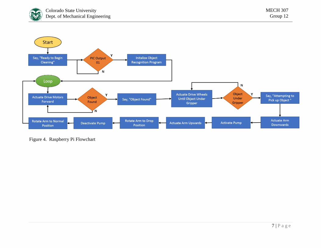
When an object has been located, and the robot has centered the object beneath the universal
gripper, labeled in Figure 4, and the arm assembly, also labeled in Figure 4, are used to pick up
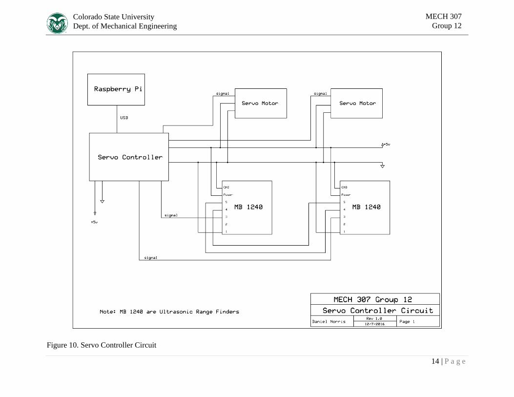
the object. The arm assembly is controlled by the Raspberry Pi by means of an external servo
controller. The servo controller allows for precise control of the tilt and extension motors without
over complicating the Raspberry Pi’s tasks. Finally, the Raspberry Pi also turns the vacuum
pump on and off during the pick up routine. Because the vacuum pump is a very noisy, high
current device, it is activated using a mechanical relay that isolates it from the rest of the circuit
as much as possible. Relay shown in Figure 3.
7 | P a g e
Colorado State University
Dept. of Mechanical Engineering
MECH 307
Group 12
Figure 4. Raspberry Pi Flowchart
8 | P a g e
Colorado State University
Dept. of Mechanical Engineering
MECH 307
Group 12
Figure 5. PIC Program Flowchart
9 | P a g e
Colorado State University
Dept. of Mechanical Engineering
MECH 307
Group 12
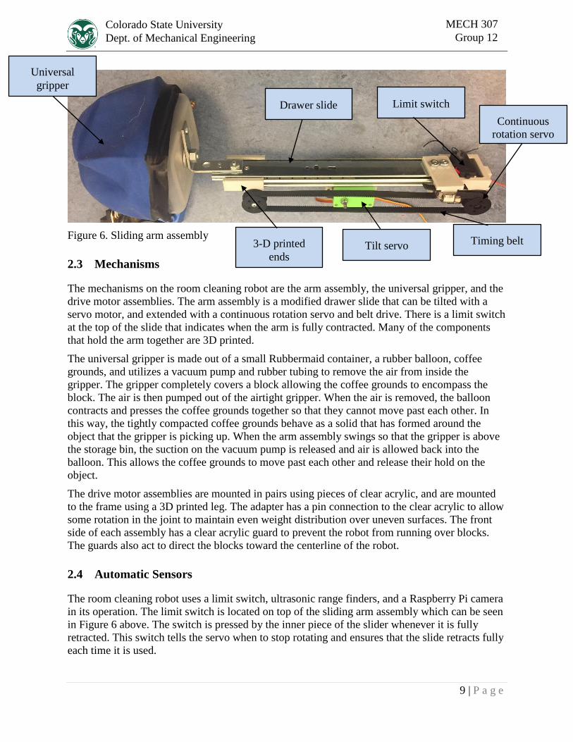
Figure 6. Sliding arm assembly
2.3 Mechanisms
The mechanisms on the room cleaning robot are the arm assembly, the universal gripper, and the
drive motor assemblies. The arm assembly is a modified drawer slide that can be tilted with a
servo motor, and extended with a continuous rotation servo and belt drive. There is a limit switch
at the top of the slide that indicates when the arm is fully contracted. Many of the components
that hold the arm together are 3D printed.
The universal gripper is made out of a small Rubbermaid container, a rubber balloon, coffee
grounds, and utilizes a vacuum pump and rubber tubing to remove the air from inside the
gripper. The gripper completely covers a block allowing the coffee grounds to encompass the
block. The air is then pumped out of the airtight gripper. When the air is removed, the balloon
contracts and presses the coffee grounds together so that they cannot move past each other. In
this way, the tightly compacted coffee grounds behave as a solid that has formed around the
object that the gripper is picking up. When the arm assembly swings so that the gripper is above
the storage bin, the suction on the vacuum pump is released and air is allowed back into the
balloon. This allows the coffee grounds to move past each other and release their hold on the
object.
The drive motor assemblies are mounted in pairs using pieces of clear acrylic, and are mounted
to the frame using a 3D printed leg. The adapter has a pin connection to the clear acrylic to allow
some rotation in the joint to maintain even weight distribution over uneven surfaces. The front
side of each assembly has a clear acrylic guard to prevent the robot from running over blocks.
The guards also act to direct the blocks toward the centerline of the robot.
2.4 Automatic Sensors
The room cleaning robot uses a limit switch, ultrasonic range finders, and a Raspberry Pi camera
in its operation. The limit switch is located on top of the sliding arm assembly which can be seen
in Figure 6 above. The switch is pressed by the inner piece of the slider whenever it is fully
retracted. This switch tells the servo when to stop rotating and ensures that the slide retracts fully
each time it is used.
Drawer slide
Timing belt
Continuous
rotation servo
Limit switch
Universal
gripper
3-D printed
ends Tilt servo
10 | P a g e
Colorado State University
Dept. of Mechanical Engineering
MECH 307
Group 12
The ultrasonic range finders are located on the front of the robot and are labeled in Figure 2. The
range finders emit a narrow beam of sound waves and let the robot know when it is close to a
large object. These sensors prevent the robot from running into things as it searches for objects to
pick up.
The Raspberry Pi camera is located at the very front of the robot and is labeled in Figure 2. The
camera detects the center of objects that stand out from the floor from an algorithm in the code.
Once the object is detected, the robot positions the object in a certain pixel range by actuating the
drive wheels. Once the object is in the desired range the robot begins the pick-up sequence.
2.5 Audio
The RCR uses synthesized voice to tell the user what stage of the cleaning process it is in. The
robot states when it has located an object and when it is going to start picking it up. The
Raspberry Pi 3 uses a text to speech software library to synthesize audible english. A two
speaker unit is mounted on the back of the robot and plugs into the 3.5mm audio jack on the
Raspberry Pi. The speakers are connected to a small amplifier that has its own on-off switch and
is powered by three AAA batteries.
11 | P a g e
Colorado State University
Dept. of Mechanical Engineering
MECH 307
Group 12
Figure 7. Functional Diagram
12 | P a g e
Colorado State University
Dept. of Mechanical Engineering
MECH 307
Group 12
Figure 8. Motor Driver Circuit Diagram
13 | P a g e
Colorado State University
Dept. of Mechanical Engineering
MECH 307
Group 12
Figure 9. PIC Microcontroller Circuit Diagram
14 | P a g e
Colorado State University
Dept. of Mechanical Engineering
MECH 307
Group 12
Figure 10. Servo Controller Circuit

15 | P a g e
Colorado State University
Dept. of Mechanical Engineering
MECH 307
Group 12
3 Design Evaluation
The final product of this semester’s efforts has proved largely successful, as all the
required functions were operational at some point during the in – lab presentation. This section
will go over each of the functional elements which were implemented and an analysis of their
use.
A LCD which displays instructions to the user during operation was the Output Display
utilized in the robot. The LCD was driven by a PIC16F88, which was coded using PICBasic to
switch between different modes of use and to display different text. The LCD operated properly
as it always displayed the correct text corresponding to the operation occurring at the given time.
An Adobe Speaker, which was attached to the frame of the robot, was the Audio Output
Device to communicate the robot’s status to the user. The speaker was attached to a battery –
powered amplifier and the amplifier was attached to the Raspberry Pi. The Raspberry Pi had
voice commands which corresponded with different actions which were taken by the robot. The
amplifier then powered the speaker enough to effectively communicate to the user. The speaker
acted accordingly and was repeatable.
The robot’s Manual User Input were three buttons which were wired to the PIC16F88
to allow a user to easily switch between the reset, cleaning, and pause modes. The buttons along
with the LCD acted as the direct user interface. The buttons were programmed very similarly to
what was done in lab, where buttons determine a visual output in another unit. The buttons were
responsive, acted as designed, and was repeatable.
A Pi Camera, Range Finder, and limit switch were used as the Automatic Sensors to
allow the robot to find an object or prevent itself from colliding with a large object, such as a
wall or a chair. The Pi Camera was able create to images of what it was seeing and therefore
assign each pixel with a color value. The Range Finder sent out a sound wave and if an object is
in the way the same sound wave reflects back into the Range Finder. The Pi Camera and the
Range Finder sent accurate information to the Raspberry Pi reliably.
The robot had many Actuators, Mechanisms, and Hardware. For the robot’s arm, a
draw slider was attached to the gripper, and lowered and raised by servo motors and a belt. The
gripper itself was a balloon with coffee in it, attached to Tupperware and had a barb connection
to a vacuum tube and vacuum pump. The vacuum pump was driven with a relay. This
mechanism worked effectively and reliably. To drive the robot, there were four DC motors
attached in the front of the robot, which were reversible due to an H – Bridge. Due to these
motors not having enough power to move the entire robot, two more motors were needed, and
they were placed as optimally as possible, but one wheel often had considerably more contact
with the ground than the other, making movement and turning unreliable. This, in turn, prevented
the robot from being in the right place to pick up objects. The robot had many components which
were connected using 3D printed parts as well.
The program codes used to implement Logic, Processing, and Control can be seen in
Appendix A. Python was the programming language used to program the Raspberry Pi, which
controlled much of the operations which were discussed in this section. This includes the audio,
automatic sensors, and actuators. The audio, range finders, and the gripper arm worked
accordingly and reliably, however the Pi Camera and the actuators for movement had some
16 | P a g e
Colorado State University
Dept. of Mechanical Engineering
MECH 307
Group 12
issues. The Pi Camera sent accurate information reliably but was not processed correctly by the
Raspberry Pi as often times the carpet was considered an object by consisting of different colors
or reflecting an excessive amount of light in a well-lit room. The DC motors used to move the
robot often fought one another to go in a specific direction, causing the robot to seize and drain
the battery. The PIC16F88 operated the LCD and the manual inputs repetitively and effectively.
17 | P a g e
Colorado State University
Dept. of Mechanical Engineering
MECH 307
Group 12
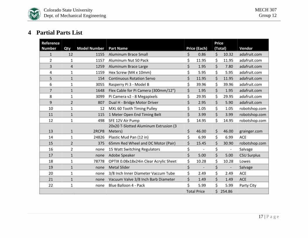
4 Partial Parts List
Reference Number Qty Model Number Part Name Price (Each)
Price (Total) Vendor
1 12 1155 Aluminum Brace Small $ 0.86 $ 10.32 adafruit.com
2 1 1157 Aluminum Nut 50 Pack $ 11.95 $ 11.95 adafruit.com
3 4 1259 Aluminum Brace Large $ 1.95 $ 7.80 adafruit.com
4 1 1159 Hex Screw (M4 x 10mm) $ 5.95 $ 5.95 adafruit.com
5 1 154 Continuous Rotation Servo $ 11.95 $ 11.95 adafruit.com
6 1 3055 Rasperry Pi 3 - Model B $ 39.96 $ 39.96 adafruit.com
7 1 1648 Flex Cable for Pi Camera (300mm/12") $ 1.95 $ 1.95 adafruit.com
8 1 3099 Pi Camera v2 - 8 Megapixels $ 29.95 $ 29.95 adafruit.com
9 2 807 Dual H - Bridge Motor Driver $ 2.95 $ 5.90 adafruit.com
10 1 12 MXL 60 Tooth Timing Pulley $ 1.05 $ 1.05 robotshop.com
11 1 115 1 Meter Open End Timing Belt $ 3.99 $ 3.99 robotshop.com
12 1 498 SFE 12V Air Pump $ 14.95 $ 14.95 robotshop.com
13 1 2RCP8 20x20 T-Slotted Aluminum Extrusion (3 Meters) $ 46.00 $ 46.00 grainger.com
14 1 24826 Plastic Mud Pan (12 in) $ 6.99 $ 6.99 ACE
15 2 375 65mm Red Wheel and DC Motor (Pair) $ 15.45 $ 30.90 robotshop.com
16 2 none 15 Watt Switching Regulators $ - $ - Salvage
17 1 none Adobe Speaker $ 5.00 $ 5.00 CSU Surplus
18 1 78778 OPTIX 0.08x18x24in Clear Acrylic Sheet $ 10.28 $ 10.28 Lowes
19 1 none Metal Slider $ - $ - Salvage
20 1 none 3/8 Inch Inner Diameter Vaccum Tube $ 2.49 $ 2.49 ACE
21 1 none Vacuum Valve 3/8 Inch Barb Diameter $ 1.49 $ 1.49 ACE
22 1 none Blue Balloon 4 - Pack $ 5.99 $ 5.99 Party City
Total Price $ 254.86
18 | P a g e
Colorado State University
Dept. of Mechanical Engineering
MECH 307
Group 12
5 Lessons Learned
Overall our group worked effectively and efficiently to get the project done by being
knowledgeable in the subject matter and being disciplined in our efforts. What went well was
having a work schedule, doing extensive research on what functions we were trying to
implement, backing up systems to ensure functionality, and organizing the different parts of the
system effectively. We could have done better at utilizing our power source, using image
processing, and creating a movement system.
Early on in the semester our group decided to meet two or three times a week to ensure we
would complete much of the more tedious and time consuming work as early as possible. This
was particularly helpful when there were unforeseen problems in the development process and
time was much more crucial.
When our group started our project, we knew we needed a way to sense objects, two mechanical
systems to move our robot and pick up objects, and a polished interface that can be easily used.
Using this knowledge, we built our robot around these functions and researched different ways to
implement and connect each system. By doing this early we were able to understand what
investment was needed to implement these systems and therefore organize our efforts more
effectively.
To ensure some type of functionality we had multiple systems in place to ensure we would be
able to fulfill each of the categories necessary for a good grade on the project. For example, our
project had two sets of actuators, one set for the gripper and one for moving the robot. When the
robot’s movement system failed, the gripper arm was able to make up for that loss. Granted,
many of these back – up systems were integral to the objective that the robot was set to do,
however it was helpful to have more than one of the tricky systems in the robot just in case one
of those systems didn’t work during the presentation.
Organizing the robot effectively not only makes the robot more aesthetically pleasing but also
allows our team to make any necessary changes or troubleshoot issues much more effectively.
One way we did this was by taping wires together and placing the majority of our boards
underneath the top shelf to prevent a gigantic rat’s nest on the top of the robot.
Our battery was often unreliable by having a perpetual lack of power or not being able to move
the robot despite charging it consistently. The battery was scrapped so it was quite old, but
functioned rather well during the majority of the testing. The battery did, however, begin to
struggle the day before presenting, and the day after presenting it was completely unusable. If we
had bought a new battery anticipating this, we would have avoided a major liability.
Our image processing system lacked reliability, as it sometimes saw the entire carpet as an
object, or did not see an object when one was within its field of vision. Many variables effected
its success as well, such as ambient light, the color of the carpet, and possible shadows from
people around the robot.
The robot’s movement system went through a few iterations, trying to balance having enough
power and allowing the robot to turn effectively. Ultimately this ended up being a weak point,
and earlier investment into the movement system would have helped the final product
considerably.
19 | P a g e
Colorado State University
Dept. of Mechanical Engineering
MECH 307
Group 12
6 References
1. "OpenCV | OpenCV." OpenCV | OpenCV. N.p., n.d. Web. 03 Dec. 2016.
http://opencv.org/
2. SparkFun. "SparkFun Vacuum Pump Gripper." YouTube. YouTube, 17 Feb. 2011. Web.
08 Oct. 2016.

A-1 | P a g e
Colorado State University
Dept. of Mechanical Engineering
MECH 307
Group 12
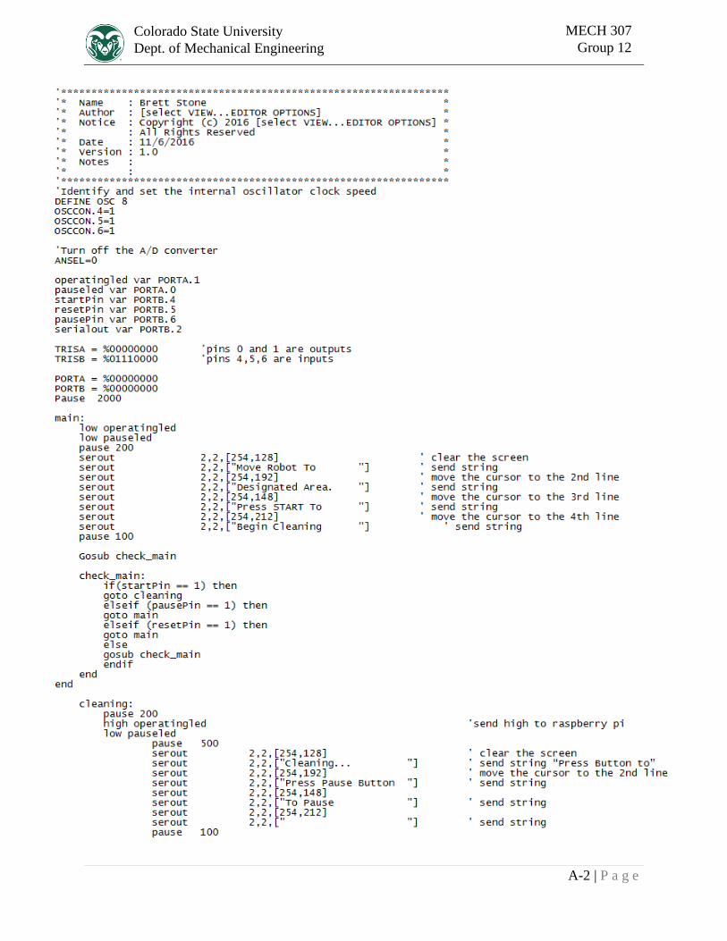
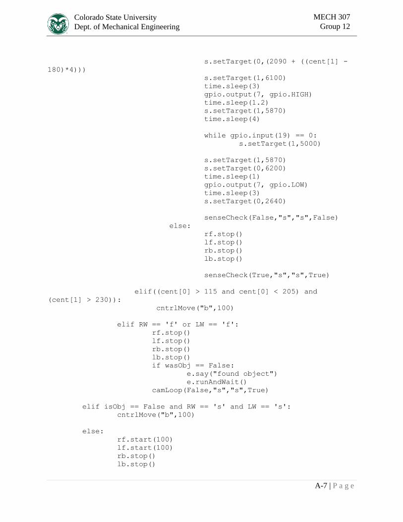
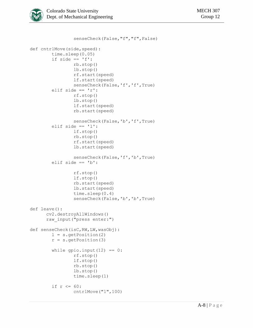
Appendix A. Program Code Used
A-2 | P a g e
Colorado State University
Dept. of Mechanical Engineering
MECH 307
Group 12
A-3 | P a g e
Colorado State University
Dept. of Mechanical Engineering
MECH 307
Group 12
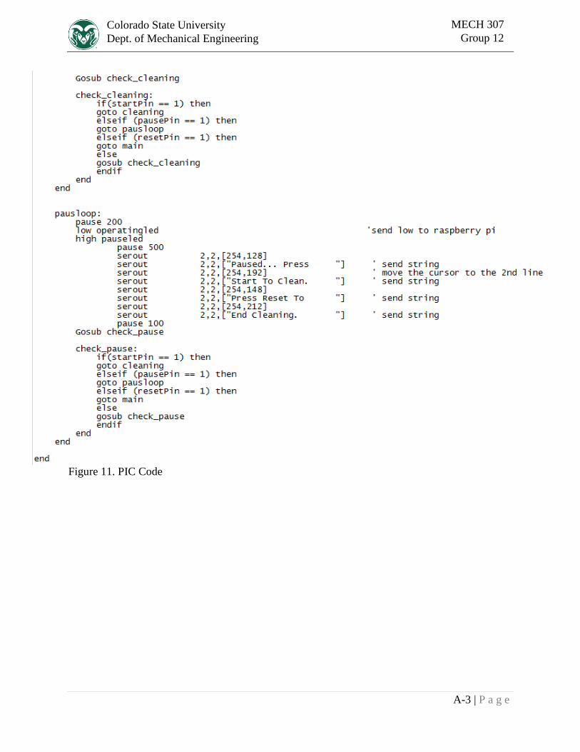
Figure 11. PIC Code
A-4 | P a g e
Colorado State University
Dept. of Mechanical Engineering
MECH 307
Group 12
import logging
sys.path.append('/usr/local/lib/python2.7/site-packages')
from collections import deque
import numpy as np
import argparse
import imutils
from picamera.array import PiRGBArray
from picamera import PiCamera
import RPi.GPIO as gpio
import time
import maestro
s = maestro.Controller()
s.setSpeed(0,40)
import pyttsx
e = pyttsx.init()
e.setProperty('rate', 100)
gpio.setwarnings(False)
gpio.cleanup()
gpio.setmode(gpio.BOARD)
gpio.setup(26, gpio.OUT)
gpio.setup(22, gpio.OUT)
gpio.setup(16, gpio.OUT)
gpio.setup(13, gpio.OUT)
gpio.setup(11, gpio.OUT)
gpio.setup(7, gpio.OUT)
gpio.setup(12, gpio.IN)
gpio.setup(15, gpio.IN)
gpio.setup(19, gpio.IN)
rf = gpio.PWM(11, 50)
lf = gpio.PWM(16, 50)
rb = gpio.PWM(22, 50)
lb = gpio.PWM(13, 50)
gpio.output(7, gpio.LOW)
s.setTarget(0,2640)
while gpio.input(19) == 0:
s.setTarget(1,5300)
s.setTarget(1,5810)
gpio.output(26, gpio.HIGH)
time.sleep(0.1)
gpio.output(26, gpio.LOW)
A-5 | P a g e
Colorado State University
Dept. of Mechanical Engineering
MECH 307
Group 12
import cv2
sys.setrecursionlimit(100000)
logging.basicConfig(stream = sys.stderr, level = logging.DEBUG)
logging.debug('Hi!')
ap = argparse.ArgumentParser()
ap.add_argument("-v", "--video",
help="path to the (optional) video file")
ap.add_argument("-b", "--buffer", type=int, default=64,
help="max buffer size")
args = vars(ap.parse_args())
buff = 120
pts = deque(maxlen=args["buffer"])
cam = PiCamera()
cam.resolution = (320,240)
cam.framerate = 30
rawC = PiRGBArray(cam, size=(320,240))
posCheck = False
time.sleep(0.1)
def camLoop(isC,RW,LW,wasObj):
cam.capture(rawC, format='bgr' , use_video_port=False)
raw = rawC.array
raw = cv2.GaussianBlur(raw, (15,15), 0)
avg = cv2.resize(raw,(1,1),interpolation = cv2.INTER_AREA)
avg = cv2.cvtColor(avg, cv2.COLOR_BGR2HSV)
avgVals = avg[0,0]
x = ((avgVals[0]-130),(avgVals[1]-200),(avgVals[2]-200))
y = ((avgVals[0]+130),(avgVals[1]+50),(avgVals[2]+50))
lower = np.array(x)
upper = np.array(y)
src = cv2.cvtColor(raw, cv2.COLOR_BGR2HSV)
mask = cv2.inRange(src.copy(), lower, upper)
cv2.bitwise_not (mask,mask)
cv2.rectangle(mask,(0,80),(95,240),color = (0,0,0), thickness
= -1)
cv2.rectangle(mask,(320,80),(225,240),color = (0,0,0),
thickness = -1)
A-6 | P a g e
Colorado State University
Dept. of Mechanical Engineering
MECH 307
Group 12
mask = cv2.erode(mask, None, iterations=2)
mask = cv2.dilate(mask, None, iterations=2)
cnts = cv2.findContours(mask.copy(),
cv2.RETR_EXTERNAL,cv2.CHAIN_APPROX_SIMPLE)[-2]
rawC.truncate(0)
center = None
if len(cnts) > 0:
c = max(cnts, key=cv2.contourArea)
((x, y), radius) = cv2.minEnclosingCircle(c)
M = cv2.moments(c)
center = (int(M["m10"] / M["m00"]), int(M["m01"] /
M["m00"]))
if radius > 35:
cv2.circle(raw, (int(x), int(y)),
int(radius),(0, 255, 255), 2)
cv2.circle(raw, center, 5, (0, 0, 255), -1)
lineUp(center,True,wasObj,isC,RW,LW)
else:
lineUp((0,0),False,False,False,RW,LW)
lineUp((0,0),False,False,isC,RW,LW)
def lineUp(cent,isObj,wasObj,isC,RW,LW):
if isObj:
if RW == 's' and LW == 's':
if(cent[0] <= 130):
cntrlMove("l",100)
isC = False
elif(cent[0] >= 190):
cntrlMove("r",100)
isC = False
elif((cent[0] > 115 and cent[0] < 205) and
(cent[1] < 180)):
cntrlMove("f",100)
isC = False
elif((cent[0] > 115 and cent[0] < 205) and
(cent[1] >= 180 and cent[1] <= 230)):
if isC == True:
e.say("picking up object")
e.runAndWait()
rf.stop()
lf.stop()
rb.stop()
lb.stop()
A-7 | P a g e
Colorado State University
Dept. of Mechanical Engineering
MECH 307
Group 12
s.setTarget(0,(2090 + ((cent[1] -
180)*4)))
s.setTarget(1,6100)
time.sleep(3)
gpio.output(7, gpio.HIGH)
time.sleep(1.2)
s.setTarget(1,5870)
time.sleep(4)
while gpio.input(19) == 0:
s.setTarget(1,5000)
s.setTarget(1,5870)
s.setTarget(0,6200)
time.sleep(1)
gpio.output(7, gpio.LOW)
time.sleep(3)
s.setTarget(0,2640)
senseCheck(False,"s","s",False)
else:
rf.stop()
lf.stop()
rb.stop()
lb.stop()
senseCheck(True,"s","s",True)
elif((cent[0] > 115 and cent[0] < 205) and
(cent[1] > 230)):
cntrlMove("b",100)
elif RW == 'f' or LW == 'f':
rf.stop()
lf.stop()
rb.stop()
lb.stop()
if wasObj == False:
e.say("found object")
e.runAndWait()
camLoop(False,"s","s",True)
elif isObj == False and RW == 's' and LW == 's':
cntrlMove("b",100)
else:
rf.start(100)
lf.start(100)
rb.stop()
lb.stop()
A-8 | P a g e
Colorado State University
Dept. of Mechanical Engineering
MECH 307
Group 12
senseCheck(False,"f","f",False)
def cntrlMove(side,speed):
time.sleep(0.05)
if side == 'f':
rb.stop()
lb.stop()
rf.start(speed)
lf.start(speed)
senseCheck(False,'f','f',True)
elif side == 'r':
rf.stop()
lb.stop()
lf.start(speed)
rb.start(speed)
senseCheck(False,'b','f',True)
elif side == 'l':
lf.stop()
rb.stop()
rf.start(speed)
lb.start(speed)
senseCheck(False,'f','b',True)
elif side == 'b':
rf.stop()
lf.stop()
rb.start(speed)
lb.start(speed)
time.sleep(0.4)
senseCheck(False,'b','b',True)
def leave():
cv2.destroyAllWindows()
raw_input("press enter:")
def senseCheck(isC,RW,LW,wasObj):
l = s.getPosition(2)
r = s.getPosition(3)
while gpio.input(12) == 0:
rf.stop()
lf.stop()
rb.stop()
lb.stop()
time.sleep(1)
if r <= 60:
cntrlMove("l",100)
A-9 | P a g e
Colorado State University
Dept. of Mechanical Engineering
MECH 307
Group 12
elif l <= 60:
cntrlMove("r",100)
else:
camLoop(isC,RW,LW,wasObj)
rf.stop()
lf.stop()
rb.stop()
lb.stop()
e.say("Ready to begin cleaning")
e.runAndWait()
senseCheck(False,'','',False)
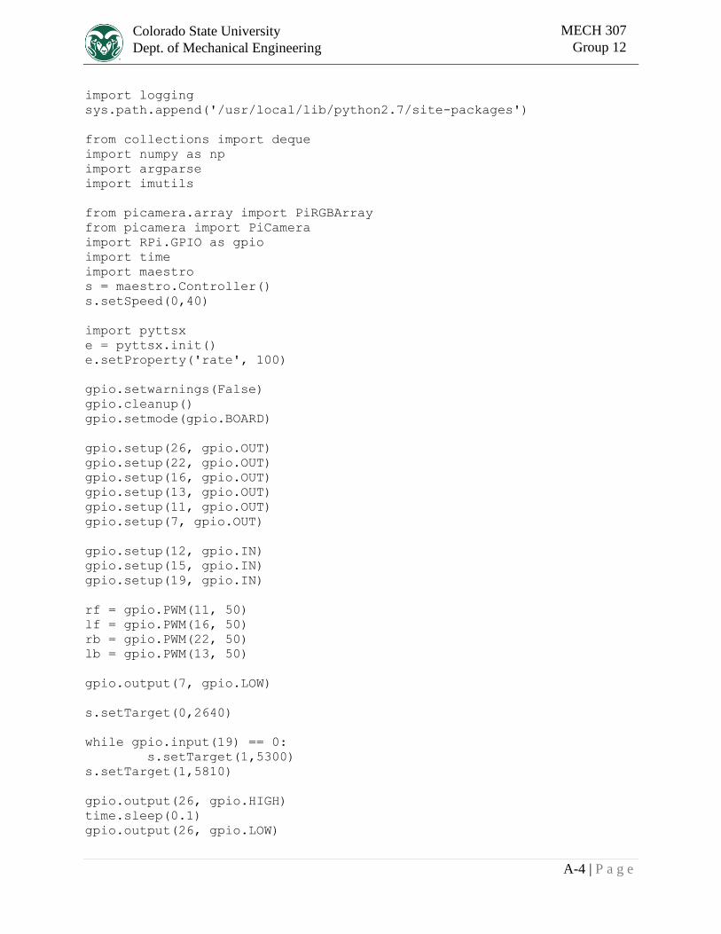
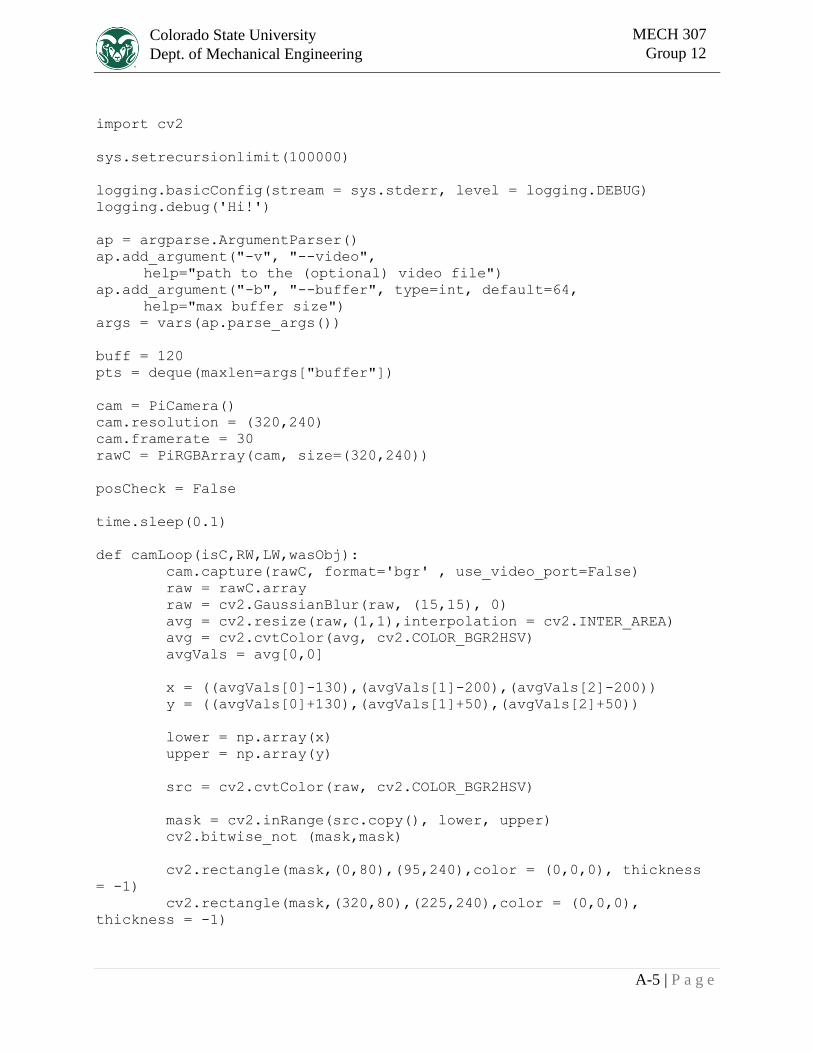
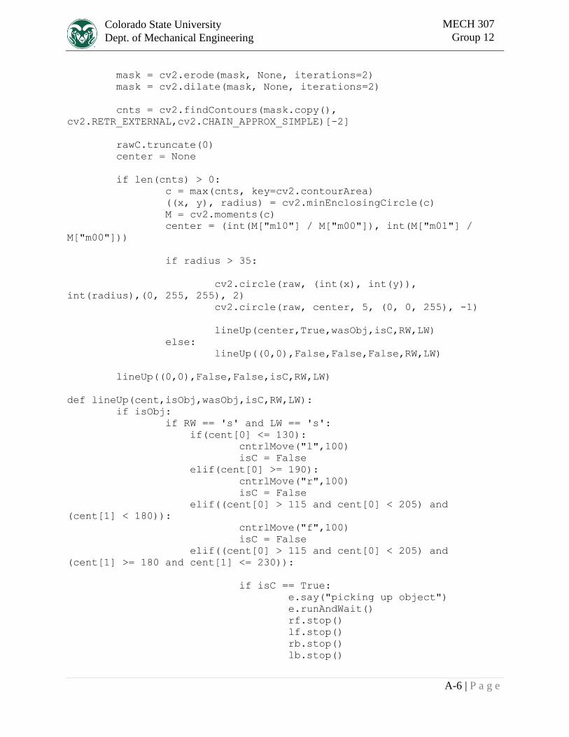
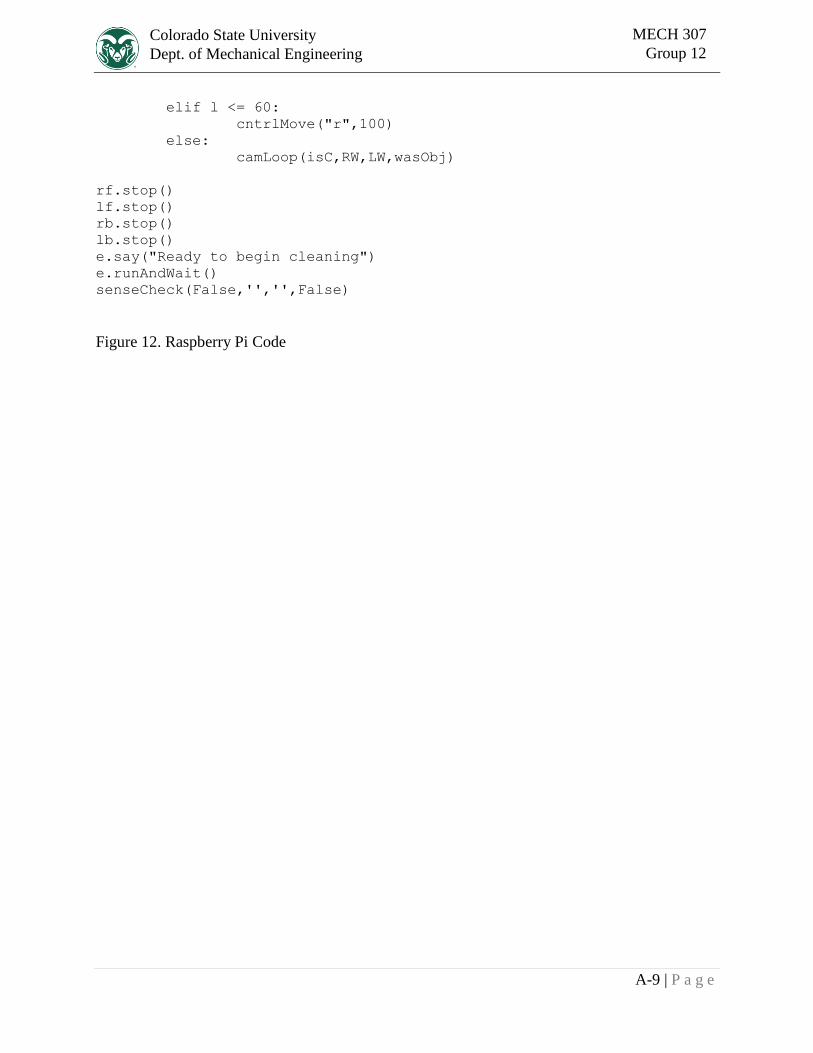
Figure 12. Raspberry Pi Code