Embed Size (px)
Citation preview

The role of real-time monitoring in controlling the installation and assessing the
performance of a Plastic Concrete Cut-off
Abstract
The construction of a plastic concrete cut-off through the core of a newly completed
embankment dam is a comparatively rare practice. This paper discusses the design, procurement,
construction and performance of the cut off wall and the role of real-time monitoring in securing
success of the works.
Site conditions required an embankment type dam and ground investigation identified extensive
granular alluvial deposits in the valley floor overlying bedrock of mudstone and sandstone. To
overcome anticipated shortfall in suitable core fill and to cut through the alluvial soils it was
proposed to install a plastic concrete cut off extending from the dam crest down in to the
bedrock.
The works required a specialist sub-contractor. Criteria for the cut-off wall was specified by the
Engineer, however the mix design and method of work was the responsibility of the specialist
subcontractor. An Independent Expert was engaged to review the proposed mix design, method
statement and quality of the cut-off works.
Construction had to overcome variable ground conditions including high pore pressures in the
core fill, obstructions in the alluvial soils, coarse granular bands and a relic slip in the bedrock.
During construction extensive monitoring was undertaken. Panel alignment was checked using
real-time readout in X and Y planes from a logger in the hydraulic grab. Real-time monitoring of
the material upstream and downstream of the cut-off was obtained from data loggers connected
to vibrating wire piezometers in the fill, alluvial soils and the bedrock. Readings were checked
against trigger levels.
Upon completion the performance of the wall was monitored as the reservoir impounded by
comparing pore pressure readings upstream and downstream of the cut-off.
This case study confirmed the importance of real-time monitoring during construction and the
need to adopt a collaborative approach to ensure satisfactory performance of the works.
William J S Sheehy BEng MSc DIC CEng MICE MCIWEM, Principal Engineer, MWH
Global, [email protected]
Donald A Bruce, BSc, DSc, PhD, CEng, FICE L.G., L.E.G., D.GE, President, Geosystems,
L.P., [email protected]
Sui Kau Alice Lim BSc MBA CEng FICE, MPUJA Director of Water Services, Public
Works Dept, Ministry of Development, Negara Brunei Darussalam
Introduction
Ulu Tutong Dam and reservoir is located in a remote jungle area of Negara Brunei Darussalam,
approximately180km south west of the capitol Bandar Seri Begawan. The dam provides some
80MCM of raw water storage and acts as a strategic reserve to regulate downstream river levels
during times of low flow.
The Client is the Department of Water Services, Ministry of Development. Design, contract
administration and supervision was by MWH. The contract was a modified version of FIDIC
Red Book 3rd
Edition (1977). The Contractor was Sinohydro Pahaytc JV.
The project included the construction of a 24km access road, 440m long, 42m high embankment
dam. Appurtenant works included a 300m long diversion tunnel, 42m high draw-off tower, fixed
weir and spillway with a discharge capacity of 12,000m3/s.
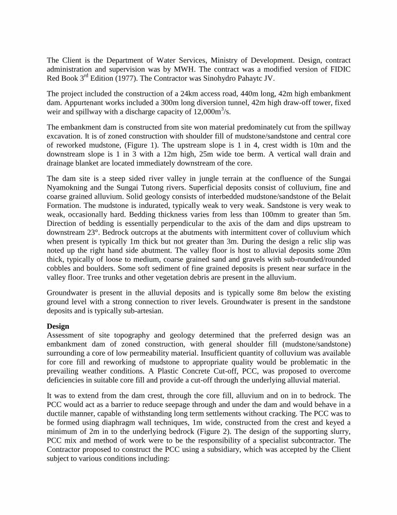
The embankment dam is constructed from site won material predominately cut from the spillway
excavation. It is of zoned construction with shoulder fill of mudstone/sandstone and central core
of reworked mudstone, (Figure 1). The upstream slope is 1 in 4, crest width is 10m and the
downstream slope is 1 in 3 with a 12m high, 25m wide toe berm. A vertical wall drain and
drainage blanket are located immediately downstream of the core.
The dam site is a steep sided river valley in jungle terrain at the confluence of the Sungai
Nyamokning and the Sungai Tutong rivers. Superficial deposits consist of colluvium, fine and
coarse grained alluvium. Solid geology consists of interbedded mudstone/sandstone of the Belait
Formation. The mudstone is indurated, typically weak to very weak. Sandstone is very weak to
weak, occasionally hard. Bedding thickness varies from less than 100mm to greater than 5m.
Direction of bedding is essentially perpendicular to the axis of the dam and dips upstream to
downstream 23°. Bedrock outcrops at the abutments with intermittent cover of colluvium which
when present is typically 1m thick but not greater than 3m. During the design a relic slip was
noted up the right hand side abutment. The valley floor is host to alluvial deposits some 20m
thick, typically of loose to medium, coarse grained sand and gravels with sub-rounded/rounded
cobbles and boulders. Some soft sediment of fine grained deposits is present near surface in the
valley floor. Tree trunks and other vegetation debris are present in the alluvium.
Groundwater is present in the alluvial deposits and is typically some 8m below the existing
ground level with a strong connection to river levels. Groundwater is present in the sandstone
deposits and is typically sub-artesian.
Design
Assessment of site topography and geology determined that the preferred design was an
embankment dam of zoned construction, with general shoulder fill (mudstone/sandstone)
surrounding a core of low permeability material. Insufficient quantity of colluvium was available
for core fill and reworking of mudstone to appropriate quality would be problematic in the
prevailing weather conditions. A Plastic Concrete Cut-off, PCC, was proposed to overcome
deficiencies in suitable core fill and provide a cut-off through the underlying alluvial material.
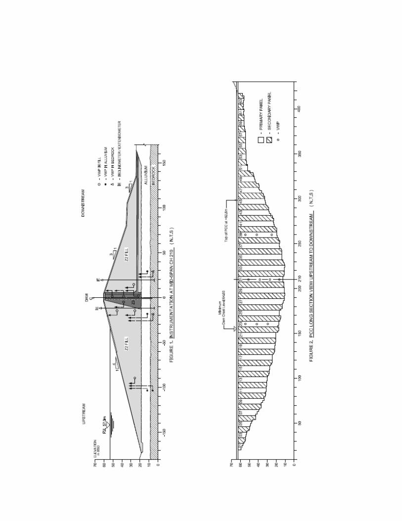
It was to extend from the dam crest, through the core fill, alluvium and on in to bedrock. The
PCC would act as a barrier to reduce seepage through and under the dam and would behave in a
ductile manner, capable of withstanding long term settlements without cracking. The PCC was to
be formed using diaphragm wall techniques, 1m wide, constructed from the crest and keyed a
minimum of 2m in to the underlying bedrock (Figure 2). The design of the supporting slurry,
PCC mix and method of work were to be the responsibility of a specialist subcontractor. The
Contractor proposed to construct the PCC using a subsidiary, which was accepted by the Client
subject to various conditions including:
Risk Panel of senior key staff from each party
Appointment of Independent Expert Reviewer
Adoption of a staged approach:
Monitoring of site and conditions
Propose and test trial mixes
Develop draft method statement to suit site conditions
Construct Trail panel
Adjust mix and method accordingly
Commence works, monitor and review methods as required
Monitoring
As the dam was not yet constructed, the behaviour of the embankment and foundation was
unknown. A detailed understanding of site conditions was obtained from instrumentation and
monitoring before the PCC works was finalised. Three cross sections of the dam and foundation
were instrumented (Figure 1). Vibrating Wire Piezometers, VWP, were installed in the founding
soil and embankment fill in key locations at each cross section to record pore pressure. In total
24 Heavy Duty High Air Entry Ceramic Filter VWP were installed in the fill and 16 Heavy Duty
Low Air Entry Ceramic Filter VWP in the founding soils. A non-vented vibrating wire pressure
transducer was provided to enable corrections for barometric pressure to the raw monitoring
data. A portable vibrating wire readout/logger was used to obtain readings from the VWP. All
the instrumentation was provided, installed, maintained and read by a specialist subcontractor.
Monitoring revealed two key issues, namely a large relic slip and high construction pore
pressures.
Relic Slip
Following removal of unsuitable material from the valley floor the instrumentation was installed
in the bedrock and alluvial soils, via rotary drilled boreholes. Embankment instrumentation was
installed as fill progressed. The landslip material up the right hand side abutment was scheduled
for removal, however the full extent and depth of the slip was not appreciated. The area of the
slip was assessed by plotting pore water pressure (pwp) response to initial fill works in the valley
floor together with movement vectors in both cross section and plan. The assessment indicated
that the relic slip covered a substantial area of reworked mudstone material, present to some 17m
below formation level and extending some 100m downstream of the dam axis. The removal of
such a large volume of material, all below the water table, would be a significant challenge. The
relic slip was found to be constrained by the field geometry, in particular the narrowing of the
river valley downstream of the dam axis and the large outcrop from the left abutment which
projects downstream and towards the right side. These features together with the substantial
berm to the downstream slope afforded sufficient stability to the embankment. It was determined
to remove all relic slip material from above formation level only.
The stability of the PCC trench during excavation of the relic slip below formation was assessed.
Undisturbed 100mm samples of the material were obtained from trial pits and sent to Hong Kong
for testing. Samples were consolidated in a triaxial cell to insitu effective stresses predicted at
end of construction. The potential failure mechanism during excavation was replicated by
gradually reducing the horizontal stress whilst maintaining vertical stress. Trench stability was
assessed with allowance for 3D effects using the procedures of Fox (2004) and trigger levels set.

An excel spreadsheet was developed and consideration given to total and effective stress
conditions either side of the PPC in core fill, alluvial deposits and relic slip mudstone. The
downstream analysis required consideration of the vertical wall drain (4m offset) as well as the
relic slip material. Analysis indicated it would be preferable to reduce the depth of PCC
excavation in the relic slip material. Loading on the PCC would be nominal given it was to be
installed post embankment construction and after significant consolidation had occurred, hence it
was not critical to key in to fresh rock. The relic slip mudstone material was of low mass
permeability and the PCC was keyed in to it until a minimum undrained strength of 130kPa
could be recorded from shear vane testing.
High construction pore pressure
Real time monitoring confirmed that pwp did not exceed trigger levels for embankment stability.
End of construction pwp in both core fill and relic slip material were well above crest level.
Piezometric levels needed to be some 1m below crest level prior to excavation of the PCC.
Dissipation rates averaged about 25mm and 70mm/day in the core fill and relic slip material
respectively taking some 7 months to reach acceptable levels.
Mix Design
Target parameters were provided in the Specification and the Contractor undertook a trail mix
programme for 12 different mixes including isotropically consolidated drained triaxial testing.
The relative compressibility of the surrounding fill to the PCC was a concern and the greatest
movement would be in the core fill. Undisturbed U100 samples of which were obtained from
embankment boreholes and values of Undrained Young’s Modulus, Eu were obtained from
isotropically consolidated undrained triaxial tests. Values of Eu for the PCC mix were inferred
from values of drained tests using standard formula. For both materials values of Eu were taken
at third of the peak Deviator Stress. The proposed PCC mix satisfied the recommendations of
ICOLD Bulletin 51 with Eu of the PCC being some 5 times that of the core fill. Erosion
resistance was assessed via a modified form of pinhole testing (USACE Tech Report REMR-
GT-15) on 28 day old 100mm diameter cylindrical samples. The no erosion criteria was satisfied.
Following completion of the trials the properties were confirmed (Table 1).
Table 1. Material Properties
Slurry prior to concreting PCC Mix
Density not greater than 1080kg/m3 Sodium Activated Bentonite grade Drillcon 11 (API 13A SEC 11)
Marsh viscosity less than 40s Water/cement ratio 2.98:1
pH range 7 to 12 Water 387kg, Cement 130kg, Bentonite 345kg, Sand 742 kg, Gravel 742kg
Sand content less than 4% Permeability on 28 day samples - less than 1x10⁻⁸
m/s
Undrained Young’s Modulus on 28 days sample 120-160MPa
UCS – 28day strength 1-1.5MPa
Slump measured at trench to be 190-210mm.
Draft method statement
The Contractor proposed to undertake a traditional method of PCC construction using a
hydraulically operated grab to excavate a sequence of primary and secondary panels. Given his
familiarity with this technology it was considered such an approach could be acceptable through
close collaboration and monitoring of PCC construction. Several iterations of the initial draft
method statement were produced before agreement was reached. A site trail panel was
undertaken to confirm the efficacy of the proposed method.
Trial Panel
A trial PCC was formed, consisting of 3 panels, two primary and one secondary, to address key
areas of concern – slurry loss in granular alluvium, excavation of boulders, trench stability,
removal of logs/stumps/timer debris, excavation of bedrock, etc. The initial site trial revealed
various problems particularly with quality at the panel joints and timber debris blocking the
airlift pump. Revisions to the method of work and controls were required. A second trial was
subsequently conducted.
Construction Method
Prior to construction several works were undertaken to reduce construction risks including:
A trench was excavated along the line of the PCC prior to starting embankment fill so to
remove any obstructions – logs, tree stumps, large boulders, etc from the alluvial soils.
All loose material and highly weathered rock was removed from the abutments and then
trimmed to a gradient not exceeding 1 in 1. All slipped material was removed from the
right abutment (some 200,000m3). The exposed abutments were mapped and bedrock
levels surveyed.
The embankment was completed some 7months prior to construction of the PCC
enabling the embankment fill and underlying founding layers to undergo significant
consolidation. The potential for load transfer and negative friction on the PCC was
greatly reduced
Boreholes were drilled through the embankment to obtain samples of fill for testing, to
confirm the lateral extent of relic slip and bedrock levels
The primary and secondary panels of the PCC were to be excavated from the crest working
platform. The hydraulic grab and spoil removal was from the upstream side of the core. Slurry,
concrete delivery and stop end insertion was from the downstream side. Spoil was deposited in
area upstream of the dam toe.
Valley thrust and sloping bedrock to valley sides
Valley thrust was not a major concern and hence shallow panels at the left abutment were
excavated first allowing the site team to gain practical experience. To reduce the risk of
undermining adjacent panels at sloping abutment areas, where the difference in base level was
significant, the lower panels were done first and work progressed up the abutment. The PCC
panel is for cut-off only and the need to have a uniform base level was not necessary, provided a
minimum embedment of 2m into rock was achieved in each bite of the panel.
Excavation – Primary Panels
Panel excavation was by a Jintai SG40A hydraulically operated grab with extended hose drum.
The grab was ZD type, round shovel with a closing force of 120tn. An electronic surveying
system on the grab provided digital readout in the cabin giving real-time monitoring in x and y
planes which could be adjusted and controlled using paddles fitted on the grab. The primary
panels comprised three bites. Initial excavation was of the two end bites, then the middle bite.
The excavated length of the primary panel is 7.2m, insertion of the two stop ends reduces it to
6.2m.

Depth and panel alignment
Bedrock was confirmed by the Engineer following visual inspection of arrisings and comparison
with surveyed bedrock level. The specified tolerance on vertical alignment of the panel was 1 in
200 and compliance of each panel bite was checked by digital real time readout from grab and
the Koden DM684. A weighted tape was also inserted as further confirmation of bite depth. On
completion of the panel a full depth plunge was made (bucket closed) in each bite to confirm
depth and alignment.
Trench cleaning
The base of the trench was cleaned of loose material by the grab, followed by an air lift pump
inserted to the base of the trench. Fresh slurry was then introduced to the trench bottom.
Displaced slurry was siphoned off to settlement ponds. The slurry was not reused but was
allowed to settle and cake prior to disposal in approved areas. During deep panel excavation the
displaced slurry was used to supplement supporting fluid in nearby panels under excavation. The
Contractor initially used a desander for cleaning and recycling of the slurry on a few shallow
panels at the left abutment. However productivity was slow with problems experienced in
achieving the specified requirements and it was not used further.
Placement of concrete
Concrete was placed via hopper in to two 200mm diameter tremmie pipes (primary panels), three
for secondary panels. Three concrete trucks were used for placement of primary panels (four
used for secondary panels). The embedment of the tremmie pipes was maintained at no less than
3m.
Stop end extraction
The procedure for stop end extraction was varied depending on panel depth, for deeper panels
greater than 35m the following was adopted:
Samples taken from bottom 1m and top 1m of the pour
Strength of plastic concrete to be a minimum of 0.125MPa as confirmed from UCS testing
Once minimum strength was achieved at the base of panel, start to remove stop end slowly –
0.5m per 0.5hr for the next 6 hours
Then check strength at top of panel; once greater than 0.125MPa increase rate of removal to
3m per hour for next 6hrs.
After which rate of extraction was to be 6m per hour
Strength test results show that the minimum strength at base of panel could be achieved after
7hrs
Excavation - Secondary Panels
The excavation of adjoining secondary panels commenced a minimum of 48hours from
completion of concreting of adjoining panels. Stop ends were first removed, then excavation of
the three bites with middle bite first followed by the end bites. The excavated length of
secondary panel was 5.2m, with removal of stop ends the total cast length of the panel was 7.2m.
Protection of joint
Trial panels revealed the susceptibility of the cast joint to damage during excavation of
secondary panel. The upper portion of the joint was protected by inserting a 7m long sheet pile
shroud to the joint. Once excavation progressed to 7m, the shroud was removed and two
rubberised buffers fitted to sides of the grab to prevent damage to deeper sections of the joint.
Cleaning of joint
For the cleaning of joints two systems were adopted. Initially a steel brush was fitted to the side
of the grab – the grab will follow the alignment of the joint parallel to the dam axis (hence
allowing for some variation from the vertical in the Y-Y plane). Once the grab brush is observed
to be clean a steel brush fitted was used. The brush is fitted with a weighted arm causing the
brush to tilt inwards against the joint face (hence allowing for some variation from the vertical in
the X-X plane) – the brush is suspended from a mobile crane and is pulled up and down the joint
face until clean with a minimum number of 26 passes required.
Schedule
The Contractor worked 7days/week, 24hrs/day in three shifts. Plant breakdown and problems
with supplies caused notable delays. Total number of panels was 64. Work commenced on the
shallow panels to the left abutment then the right abutment before going back to the left
abutment area, progressing upwards to the shallow panels. With abutment areas completed
excavation moved to the valley floor area, progressing from the right (area of relic slip) to the
left. The cycle time per panel from start of excavation to end of concreting was on average 66hrs.
Total volume of concrete placed was 13,865m3. Actual to theoretical concrete use per panel gave
an average over break of 13%. Average rate of concrete placement was 32m3/hr with a rate of
rise in the panel of 5.2m/hr.
Monitoring during construction
VWPs were located either side of the core in each material at three panels 23, 31 and 39 (Figure
2). The frequency of readings via the data loggers varied from 5min to hourly depending on the
nature of the works. All readings were monitored against trigger levels. Plots of increase in
piezometric level from start of excavation until completion of concreting are given below for the
three instrumented panels (Figure 3). Start and end times for excavation, cleaning and placing of
concrete are also shown. Excavation was seen to cause a modest increase in piezometric levels
by up to 1.4m, some 4%. Trigger levels were not exceeded and pwp was observed to dissipate
during cleaning. Chiselling coupled with placement of temporary backfill (to panel 31) caused a
significant increase in piezometric level of up to 5.3m, some 16%. Although trigger levels were
not exceeded careful control of the chiselling procedure was required. Placement of plastic
concrete caused the greatest increased in piezometric level of up to 7.3m, some 22% as pressure
was exerted by the wet plastic concrete on to the walls of the excavation.
Panel Alignment
Real time monitoring during excavation of the panels enabled alignment to be controlled to
specified limits save for one panel, number 64. A hard sandstone layer was encountered in the
bedrock at the base of this end panel causing the grab to kick towards the downstream and the
panel to go out of tolerance. This is not a major issue here given the location and shallow depth
of panel 64 and a connection with the adjoining panels was still achieved.
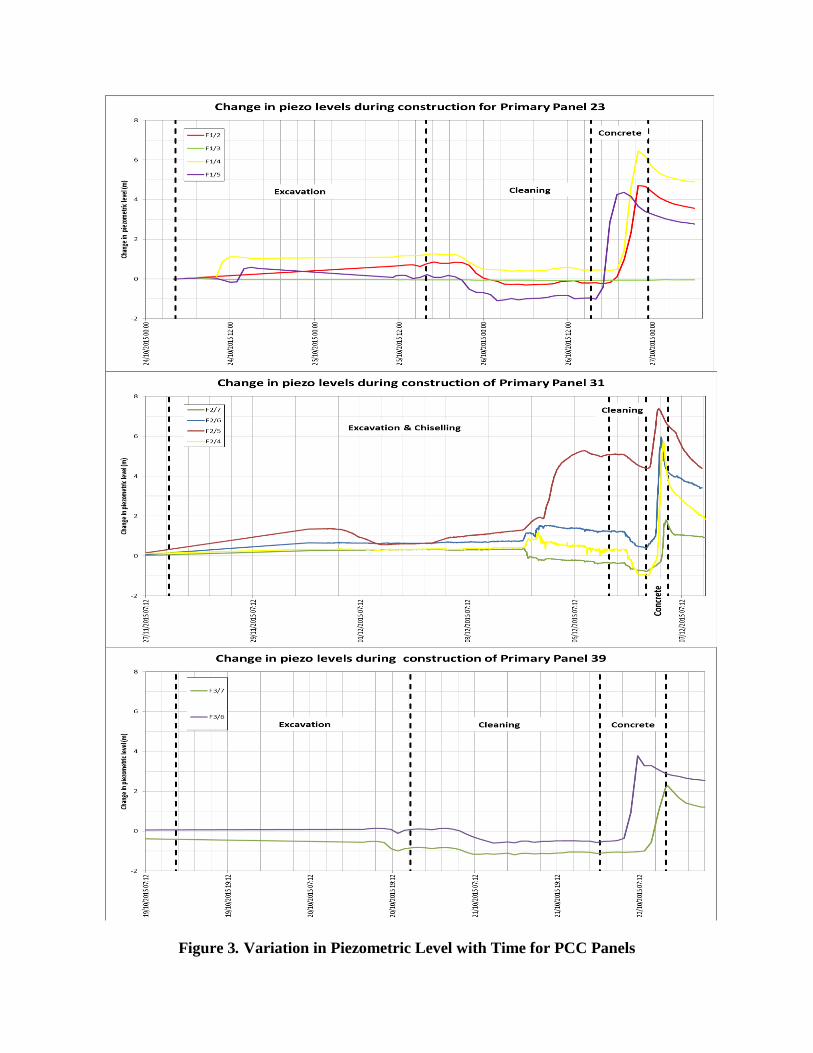
Figure 3. Variation in Piezometric Level with Time for PCC Panels
Trench stability/rapid slurry loss
Slurry levels in the trench were constantly monitored and maintained at no greater than 0.6m
below top of guide wall.
Localised collapse at joints
Koden readings taken on secondary panels recorded localised collapse issues at joints to Panels
16, 18, 20 and 22. It is considered that prolonged periods (up to 17days) where joints were left
‘open’ resulted in softening of the surrounding core fill. Koden readings confirm that the
presence of these collapse features was isolated to the joints only and was restricted to the near
surface. The largest was at joint between panels 21 and 22 which extended from underside of
guide wall down 2.8m, maximum of 1m wide at the top and extended some 2m long from joint
face. Remedial work involved installation of a shutter below and along the line of the internal
face of the guide wall then backfill bite with arrisings. All loose material was removed from
underneath the guide wall and concrete infill placed to fill the subsequent void.
Obstructions
During excavation of the first bite for primary panel 31 (mid valley) an obstruction was
encountered at 48m depth. A crest borehole at this panel location recorded bedrock at 51m. The
grab was unable to excavate the obstruction and a chisel was needed to advance. Fortuitously this
panel was instrumented and VWP readings could be used to monitor and control the chiselling.
Control of the drop height was restricted to 1.5m to reduce potential for shockwaves/vibrations
to propagate up to the wall drain – the base of which was some 6m above current base of trench.
The bentonite slurry also helped to dampen vibrations as density was already 1.12. The following
procedure was adopted for dealing with obstructions using a 4tn, 0.98m diameter by 2m long
chisel:
1. Take Koden readings for each chisel line (LHS, RHS and middle of the 2.8m long bite)
2. Slurry density not to be less than 1.1
3. Set data loggers in VWPs to read at 10min time intervals and monitor pwp
4. Park 20tn dumptruck with mudstone fill adjacent to panel as emergency backfill material
5. Move grab/crane/truck away from panel footprint
6. Install chisel to bottom of panel
7. Drop height of chisel not to exceed 1.5m
8. Apply chisel for 30mins – monitoring pwp throughout - if excessive then stop chisel
9. Remove chisel and insert koden to check any variation to trench width.
10. Insert hydraulic grab to remove arisings
11. Repeat points items 6-10 until hard material is removed.
A bailer was used during trench cleaning to assist with removal of the high density slurry. Koden
readings taken on completion found that the integrity of the trench was maintained throughout.
During excavation of the second bite the obstruction was again encountered, as a precaution the
first bite was backfilled with arissings whilst the remaining sections were excavated. A notable
increase in pwp readings was recorded with placement of this backfill (Figure 3, piezo F2-5).
Monitoring post impoundment
Performance of the wall is assessed through comparison of pwp readings upstream and
downstream of the core following impoundment of the reservoir. Graphs are plotted of
piezometric level against reservoir level to assess how increases in reservoir level effect pwp’s
downstream of the PCC. A direct relationship would give a ratio of 1 and steep gradient to the
graph of 45 °, no relationship would give a horizontal line and a ratio of zero.
Figure 4: Upstream bedrock - Downstream bedrock
As expected the relationship between reservoir level and pwp in the bedrock upstream of the
PCC was very strong, with a steep inclination to the graph and a peak ratio of 0.97.
Downstream of the PCC this is significantly reduced, the ratio varies from 0 to a peak of
0.43. The peak ratio occurs at mid valley, the lowest bedrock area and zone of maximum
head; whilst the piezometric level here is influenced by reservoir level it is stable.
Figure 4: Upstream alluvium - Downstream alluvium
As expected the relationship between reservoir level and pwp in the alluvial soils upstream of
the PCC was very strong with a ratio of 1. Downstream of the PCC this is significantly
reduced as the ratio drops to 0.19.
Upstream Zone 3 (core fill) - Downstream Zone 3
Pwp in the core fill upstream of the PCC is virtually independent of reservoir level. Pwp in
the core fill downstream of the pcc has a similar limited relationship with reservoir level.
Upstream Zone 2 (shoulder fill) - Downstream Zone 2
The relationship between reservoir level and pwp in the shoulder fill upstream of the PCC
was limited. Downstream of the pcc no relationship between pwp and reservoir levels is
observed and the ratio is 0, the plot line horizontal.
Conclusions
This case study confirmed the importance of adopting a staged, collaborative approach to the
works and emphasised the key role real-time monitoring has during construction to ensure
satisfactory performance of the works.
Acknowledgements
The authors would like to thank the Department of Water Services, Public Works Department,
Ministry of Development, Negara Brunei Darussalam for permission to publish this paper.
The advice and guidance of Dr Donald Bruce who acted as Independent Expert Reviewer for the
PCC works is much appreciated. The hard work and diligence of my site staff together with the
support of the engineering team Doug McLearie, Ian Carter and Matthew Hill was invaluable.
References
BS (2000) BS EN 1538:2000 European Standard for Diaphram Walls
FIDIC (1977) Conditions of Contract (International) for Works of Civil Engineering
Construction 3rd Edition, Federation Internationale des Ingenieurs-Conseils
Fox P.J. (2004) Analytical Solutions for Stability of Slurry trench Journal of Geotechnical and
Geoenvironmental Engineering ASCE July pp 749-758
ICE (1990) Specification for the construction of slurry trench cut-off walls as barriers to
pollution migration
ICOLD Bulletin 51 (1985) Filling Materials for watertight cut off walls
Kahl TW, Kauschinger JL and Perry EB (1991) Technical Report REMR-GT-15 Plastic
Concrete cutoff walls for earth dams Department of the Army USACE

Fi
gu
re
4.
Pi
ez
o
m
et
ric
Le
ve
ls
U
ps
tr
ea
m
an
d
D
o
w
ns
tr
ea
m
of
PC
C