Embed Size (px)
Citation preview
ASM-FRA- A542372 Version: 9.0
Substation Asset Methodology – Framework
Current version: 16/11/2020 INTERNAL USE Page 3 of 30
Next revision due: 16/11/2022 HARDCOPY IS UNCONTROLLED © Powerlink Queensland
Table of contents
Version history .................................................................................................................................................................... 2
1. Introduction ........................................................................................................................................................... 5
1.1 Purpose ................................................................................................................................................................... 5
1.2 Scope ....................................................................................................................................................................... 5
1.3 Objectives ................................................................................................................................................................ 5
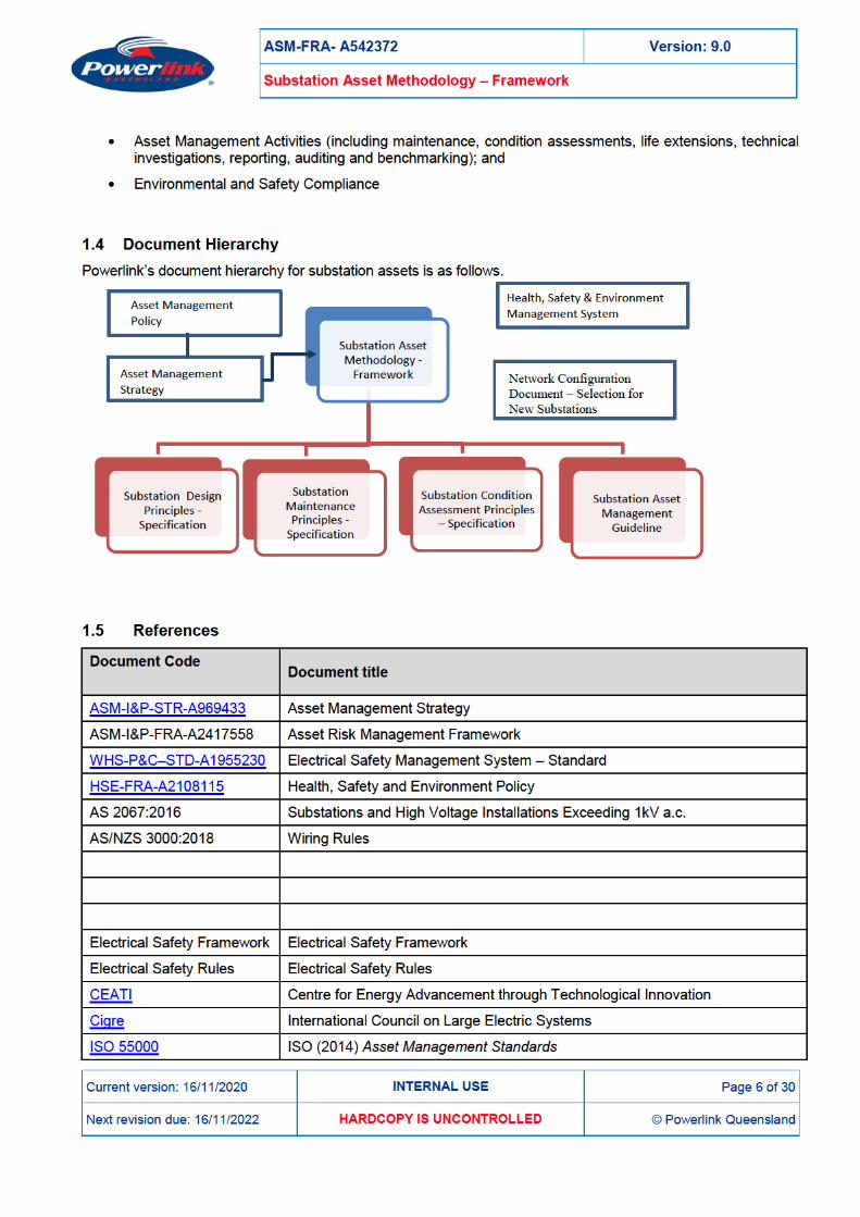
1.4 Document Hierarchy .............................................................................................................................................. 6
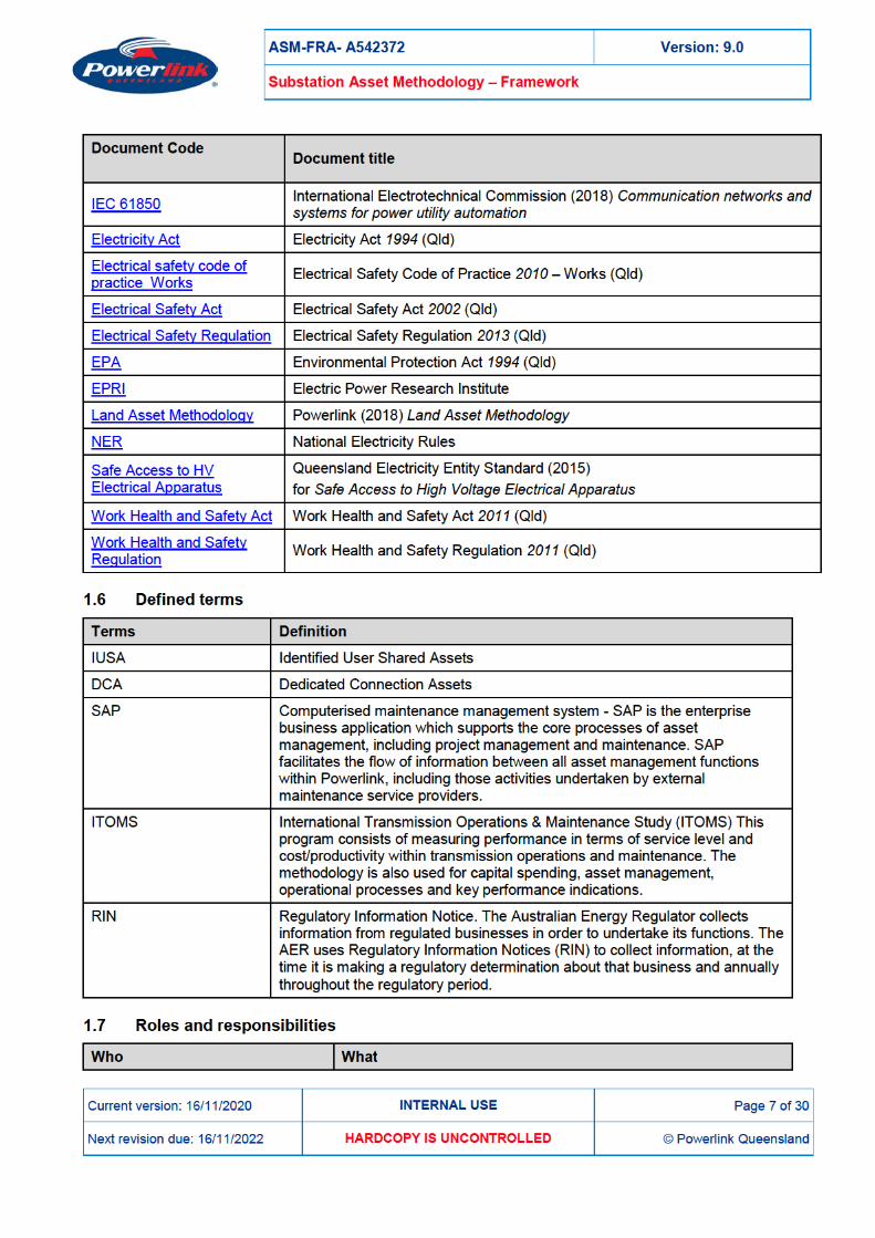
1.5 References .............................................................................................................................................................. 6
1.6 Defined terms ......................................................................................................................................................... 7
1.7 Roles and responsibilities ..................................................................................................................................... 7
1.8 Monitoring and compliance ................................................................................................................................... 8
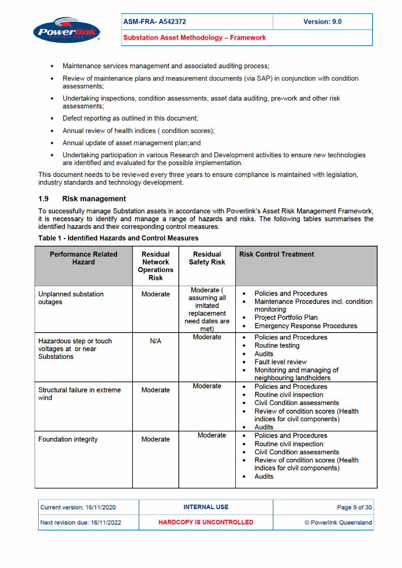
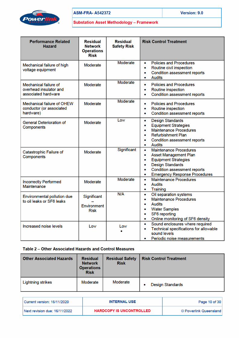
1.9 Risk management .................................................................................................................................................. 9
2. Framework ........................................................................................................................................................... 12
2.1 Asset Profile .......................................................................................................................................................... 12
2.2 Stakeholder Requirements ................................................................................................................................. 12
2.2.1 Safety Compliance ....................................................................................................................................... 12
2.2.2 Environmental Compliance ......................................................................................................................... 13
2.2.3 Availability and Reliability of Supply .......................................................................................................... 14
2.2.4 Conformance with National Electricity Rules ........................................................................................... 14
2.2.5 Connection Agreements .............................................................................................................................. 15
3. Lifecycle Management ....................................................................................................................................... 15
3.1 The Planning and Investment stage .................................................................................................................. 16
3.2 Operation, Maintenance and Refurbishment stage ........................................................................................ 17
3.2.1 Maintenance.................................................................................................................................................. 18
3.2.1.1 Routine scheduled ....................................................................................................................................... 18
3.2.1.1.1 Routine Substation Maintenance (RSM) .............................................................................................. 18
3.2.1.1.2 Service Level Maintenance ..................................................................................................................... 18
3.2.1.1.3 Overhaul .................................................................................................................................................... 18
3.2.1.2 Condition based ............................................................................................................................................ 18
3.2.1.3 Emergency Corrective ................................................................................................................................. 19
3.2.1.4 Deferred Corrective ...................................................................................................................................... 19
3.2.1.5 Maintenance Support................................................................................................................................... 19
3.2.2 Refurbishment .............................................................................................................................................. 20
3.3 End of Life ............................................................................................................................................................. 21
ASM-FRA- A542372 Version: 9.0
Substation Asset Methodology – Framework
Current version: 16/11/2020 INTERNAL USE Page 4 of 30
Next revision due: 16/11/2022 HARDCOPY IS UNCONTROLLED © Powerlink Queensland
4. Asset Management Drivers ............................................................................................................................... 21
4.1 Condition Assessment ......................................................................................................................................... 22
4.1.1 Condition Assessment Process ................................................................................................................. 22
4.1.2 Condition Data .............................................................................................................................................. 22
4.1.2.1 Plant Item Level ............................................................................................................................................ 22
4.1.3 Engineering Data .......................................................................................................................................... 23
4.1.4 Condition Assessment Report .................................................................................................................... 23
4.2 Technical Investigations and Research ............................................................................................................ 24
4.3 Innovation, Technology and Emerging Issues ................................................................................................. 24
4.3.1 Climate Change Adaptation ........................................................................................................................ 24
4.3.2 Connection of renewable energy sources ................................................................................................ 24
4.3.3 Internet of Things (Substations Digitalisation) ......................................................................................... 25
4.3.4 Use of Unmanned Aerial Vehicles (UAV) ................................................................................................. 25
5. Emergency Response and Network Security ................................................................................................ 25
5.1 Emergency Response ......................................................................................................................................... 25
5.2 Network Security .................................................................................................................................................. 26
6. Supporting Activities ......................................................................................................................................... 26
6.1 Risk Management ................................................................................................................................................ 26
6.2 Project Handovers................................................................................................................................................ 26
6.3 Strategic Spares ................................................................................................................................................... 26
6.4 Technical Training ................................................................................................................................................ 27
6.5 Documentation ..................................................................................................................................................... 27
6.6 Strategic Linkages................................................................................................................................................ 27
6.7 Benchmarking ....................................................................................................................................................... 27
7. Health, Safety and Environment ...................................................................................................................... 27
8. Forward Planning ............................................................................................................................................... 28
9. Distribution list .................................................................................................................................................... 29
Appendix A List of Documentation to be provided at Project Handover ......................................................... 30
ASM-FRA- A542372 Version: 9.0
Substation Asset Methodology – Framework
Current version: 16/11/2020 INTERNAL USE Page 5 of 30
Next revision due: 16/11/2022 HARDCOPY IS UNCONTROLLED © Powerlink Queensland
1. Introduction
1.1 Purpose The role of Powerlink’s asset management system is to ensure the organisation’s assets are managed in such manner to meet customer needs, optimise flexibility and be cost-efficient. The practices seek to achieve a balance between reliability (customer need), managing risk (strategic, statutory, legislative and compliance, safety and environmental and people and stakeholder related risks) and efficiency (customer and stakeholder need). In order to implement the organisation’s Asset Management Strategy specific asset management methodologies must be developed for each major asset group within Powerlink.
This document sets out the whole of life management philosophy for Substation High Voltage Plant and Infrastructure covering all three stages (Plan and Invest, Operate and Maintain and End of Life) of an asset life cycle (as per ISO 55000). These three life cycle stages are further divided throughout this document into planning, design, acquisition/procurement, construction and installation, commissioning, operation, maintenance, modification/refurbishment (incl. renewal and life extension) and disposal/decommissioning stages. This document acts as a reference for the development of maintenance and project budgets and forecasts.
1.2 Scope The scope of this document covers the asset life cycle of the following high voltage substation plant and substation infrastructure components:
• all high voltage substation equipment (including circuit breakers, disconnectors, instrument transformers, earth switches, surge arrestors, power transformers, earthing transformers);
• all busbars and conductors (overhead) located inside substations fences and maintained by Powerlink;
• all reactive plant (including all capacitor banks, series and shunt reactors, earth reactors/resistors, static VAr compensators, statcom devices);
• all substation site infrastructure including station supplies ( station supply transformers and standby supply generators and associated equipment), substation earthing system ( including earth grids and all earth connections), site establishment (access road and internal substation roadways, substation security system (including fences), drainage and oil containment systems and blast walls and signage);
• all structures and foundations located within substations and maintained by Powerlink, excluding communication and transmission line structures;
• all substation land within the substation security fence and to a distance of five meters outside (excluding helipad and vegetation maintenance outside fence);
• all substation buildings including work sheds and other storage facilities, fire protection systems, cable trenches, switchyard lights and associated high voltage(>1kV) power cabling located inside substations; and
• compressed air systems, where applicable.
1.3 Objectives This Methodology/Framework forms a part of Powerlink’s asset management system.
The Substation Asset Methodology sets out how the following key performance areas are to be addressed:
• Levels of Service;
• Lifecycle Management;
• Asset Management Drivers;

ASM-FRA- A542372 Version: 9.0
Substation Asset Methodology – Framework
Current version: 16/11/2020 INTERNAL USE Page 11 of 30
Next revision due: 16/11/2022 HARDCOPY IS UNCONTROLLED © Powerlink Queensland
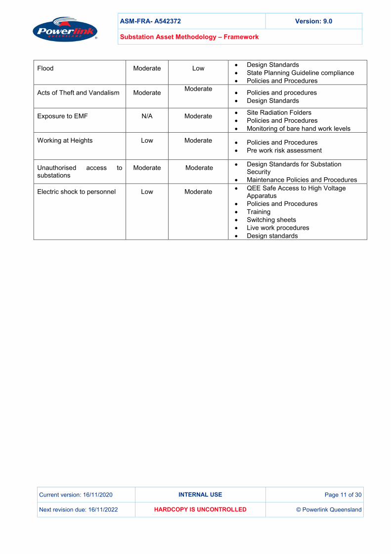
Flood Moderate Low
• Design Standards • State Planning Guideline compliance • Policies and Procedures
Acts of Theft and Vandalism Moderate Moderate
• Policies and procedures • Design Standards
Exposure to EMF N/A Moderate
• Site Radiation Folders • Policies and Procedures • Monitoring of bare hand work levels
Working at Heights Low
Moderate
• Policies and Procedures • Pre work risk assessment
Unauthorised access to substations
Moderate Moderate
• Design Standards for Substation Security
• Maintenance Policies and Procedures
Electric shock to personnel Low
Moderate
• QEE Safe Access to High Voltage Apparatus
• Policies and Procedures • Training • Switching sheets • Live work procedures • Design standards

ASM-FRA- A542372 Version: 9.0
Substation Asset Methodology – Framework
Current version: 16/11/2020 INTERNAL USE Page 12 of 30
Next revision due: 16/11/2022 HARDCOPY IS UNCONTROLLED © Powerlink Queensland
2. Framework
2.1 Asset Profile Powerlink owns, maintains and operates substation plant at a range of voltages. Nominal transmission voltages in the network include 330kV, 275kV, 132kV and 110kV although some substation equipment operates at lower voltages typically for the purposes of providing customer connections, substation local supply and as a part of reactive support plants. An overview of the number of assets covered by this methodology is provided in the Powerlink Annual Report. For the purpose of this document, switching stations are treated as substations.
2.2 Stakeholder Requirements Powerlink has a large number of stakeholders whose requirements are defined through various state and federal laws and regulations, connection access agreements, procurement agreements, National Electricity Rules, customer and consumer panels and landholder relations rules.
2.2.1 Safety Compliance Powerlink is required to ensure substations are secured, maintained and operated in a manner that is electrically safe and complies with the Electrical Safety Act, Electrical Safety Regulation, the Work Health and Safety Act, Work Health and Safety Regulation, and relevant Codes of Practice (including Safety in Design and AS 3000). These requirements are aligned in Powerlink’s Health Safety and Environment Policy and Electrical Safety Framework.
The Work Health and Safety Act requires the safety risk to be eliminated or minimised so far as is reasonably practicable (SFAIRP). In Powerlink this is facilitated by utilising a corporate risk matrix to make appropriate decisions related to planning, acquisition, design, construction, commissioning, operation, maintenance, refurbishment, replacement and disposal of the substation high voltage equipment and other substation plant.
To design substations that ensure safe access to primary plant, Powerlink utilises the Queensland Electricity Entity Standard for Safe Access to High Voltage Electrical Apparatus.
To ensure substations are safe and are operated in a way that is electrically safe, Powerlink has established design and maintenance measures.
Design measures include:
• Safety in Design as per the Work Health and Safety Act;
• adequate electrical and maintenance clearances;
• adequate perimeter fencing (substation security fence) and adequate substation building security systems;
• earthing arrangements to restrict step and touch potentials and transfer voltages;
• protection systems including circuit breaker fail scheme;
• adequate and accurate signage;
• adequate structural soundness;
• adequate mechanical links;
• restricted/controlled access to substations (authorised personnel only);
• adequate training for substation entry authorisation;
• asbestos registers;
• radiation folders;
• mechanical barriers; and
ASM-FRA- A542372 Version: 9.0
Substation Asset Methodology – Framework
Current version: 16/11/2020 INTERNAL USE Page 13 of 30
Next revision due: 16/11/2022 HARDCOPY IS UNCONTROLLED © Powerlink Queensland
• SF6 equipment low gas alarms and trips.
Maintenance measures include:
• routine inspections of high voltage equipment and other plant and substation security patrols;
• monitoring of outage data;
• routine earthing system tests;
• routine service of major equipment;
• routine SF6 and oil sampling where appropriate;
• on line condition monitoring (routine and condition based) as applicable;
• working at heights procedures;
• condition assessment reports; and
• restricted access zones when required.
In addition the annual calculation of fault levels is performed followed by a review of continuous current and fault current ratings of substation plant.
2.2.2 Environmental Compliance Over the asset life cycle, substations are operated and maintained in compliance with relevant environmental legislation.
During the planning and investment phase, environmental compliance issues within an existing or new substation under construction are managed within Powerlink’s Health Safety and Environment Policy, based on specific Environmental Work Plans that address the relevant compliance issues for the site and works. The handover of newly constructed assets into the operation and maintenance phase provides a stage-gate that ensures the assets meet environmental compliance criteria. In accordance with Code of Practice – Maintenance of Electricity Corridors and Infrastructure in Queensland Parks and Forests, Environmental Work Plans (EWP) are established for each site for ongoing management of environmental compliance issues. This allows for a structured approach that provides mechanisms for continual improvement or refinement of management practices.
In the operation and maintenance phase of the substation asset, significant most common environmental compliance issues include containment of insulating materials (hydrocarbons and SF6) and suspended solids, soil erosion and sedimentation, site drainage and noise generated by substation plant.
Powerlink has implemented a range of compliance monitoring strategies that involve:
• establishment of oil containment systems;
• routine testing and sampling of substation oil containment and discharge systems;
• monitoring, detection and management of SF6 leaks using on line SF6 density trending and specialised detection camera technology including annual reporting;
• programs of routine civil inspection to monitor the effectiveness of site drainage and detects presence of excessive soil erosion and sedimentation issues;
• programs of routine substation electrical plant inspection to monitor the integrity of oil containment systems and any other vessels containing insulating fluids;
• management of asbestos containing materials;
• responsible disposal of contaminated materials and equipment;
• provision of oil spill kits;
• periodic oil testing to monitor polychlorinated biphenyl (PCB) content ;
ASM-FRA- A542372 Version: 9.0
Substation Asset Methodology – Framework
Current version: 16/11/2020 INTERNAL USE Page 14 of 30
Next revision due: 16/11/2022 HARDCOPY IS UNCONTROLLED © Powerlink Queensland
• effective dealing with any noise complaints;
• Undertaking noise modelling for new substation sites and established site where new equipment is planned to be installed; and
• Use of sound enclosures and technical specifications defining acceptable noise levels.
Management of physical access to substations and of the surrounding land is addressed within the Land Asset Methodology Framework.
The land inside the substation is managed in a similar way but at a different frequency to ensure adequate availability and reliability of electricity supply.
2.2.3 Availability and Reliability of Supply Powerlink's reliability of supply obligations stem from a combination of our Transmission Authority, associated state legislation and the National Electricity Rules. In addition, the Australian Energy Regulator imposes and monitors a number of performance criteria (STPIS –Service Target Performance Incentive Scheme) associated with availability of transmission network critical and non-critical elements.
For substation assets, a fundamental determinant for reliability and availability of supply involves establishing the optimum minimal but flexible substation configuration at the design stage of the lifecycle, which requires balancing reliability against capital expenditure for each configuration. For higher reliability requirements related to the 275kV transmission backbone and major customers, a more robust configuration is typically employed (e.g. breaker and a half arrangement). Where a lower level of reliability is considered appropriate, which generally applies to 132kV and 110 kV network assets, a less robust configuration is employed (e.g. folded bus or H bus arrangements). A separate asset management document for network configuration informs development of options for the investment decision-making process.
In the operation and maintenance phases of the asset life cycle, the use of live substation techniques to reduce maintenance outages and improve reliability and availability has been broadly implemented. Powerlink employs live substation techniques to significantly reduce the requirement for 275kV network outages, and higher risk outages affecting multiple network elements (e.g. busbars) and major customer loads. Further exploitation of live substation techniques is pursued as part of this methodology to continue to optimise reliability and availability of supply outcomes while maintaining safety targets.
On an ongoing basis, Powerlink monitors the performance of substation asset availability using a Forced Outage Database and associated processes to continually review the root cause of each event and establish improvement actions. Monitoring of equipment performance and availability is also achieved through annual review of condition scores (health indices) utilising data collected through routine, condition based and corrective maintenance activities. The detailed condition assessments, maintenance audits and on-line monitoring of plant is also employed and utilised to identify change in reliability and availability of substation assets. In addition, Powerlink produces an Asset Management Plan which is updated on an annual basis and provides an overview of possible future capital investment projects as well as significant forecasted operational refurbishment projects. Planned and timely replacement or planned and timely de-energisation (retirement) of substation high voltage equipment greatly contributes to the increased availability and reliability of the transmission network and to the maintaining of safety targets.
2.2.4 Conformance with National Electricity Rules As a registered Transmission Network Service Provider, Powerlink is obliged to conform to the relevant National Electricity Rules that govern the operation of the National Electricity Market.
In terms of conforming to the National Electricity Rules, the selection of plant and equipment forming part of the substation asset must support a range of outcomes, including but not limited to:
• function through a range of voltages and frequencies;
• adequate thermal and short term (fault) ratings;
• provide accurate metering installations through the installation and maintenance of instrument transformers consistent with accuracy class requirements;
ASM-FRA- A542372 Version: 9.0
Substation Asset Methodology – Framework
Current version: 16/11/2020 INTERNAL USE Page 15 of 30
Next revision due: 16/11/2022 HARDCOPY IS UNCONTROLLED © Powerlink Queensland
• achieve required fault clearance times through installation of circuit breakers with appropriate operating characteristics, in conjunction with the associated protection system; and
• supply of adequate AC and DC systems to support required reliability and availability for protection schemes.
2.2.5 Connection Agreements Connection access agreements specify each customer’s requirements with regards to the availability and reliability of connection which impacts substation connection arrangements and determines connection point details.
Powerlink has an established business process for obtaining outages that involves negotiation with all interested parties (generators and customers). In addition, Powerlink has competency in live work to reduce the impact of routine and some condition based maintenance and projects on the electricity market.
On an annual basis, Powerlink reviews the minimal number of insurance and maintenance spares in order to meet the requirements of a dynamic and very diverse substation plant population. Where and when necessary Powerlink will also use Network Support agreements and load curtailment measures. All planned outages are managed and co-ordinated by Network Operations.
When dealing with potential new non regulated connections to the transmission network, Powerlink identifies parts of the connection access assets that are subjected to the contestability rule (as defined by AER). This rule defines two types of connection assets:
• A dedicated connection asset (DCA) services in which design, construction, ownership, operation and maintenance can be provided by any party on commercial terms; and
• Contestable Identified User Shared Assets (IUSA) which can be designed, constructed and owned by a third party but for which Powerlink will be responsible for operation and maintenance.
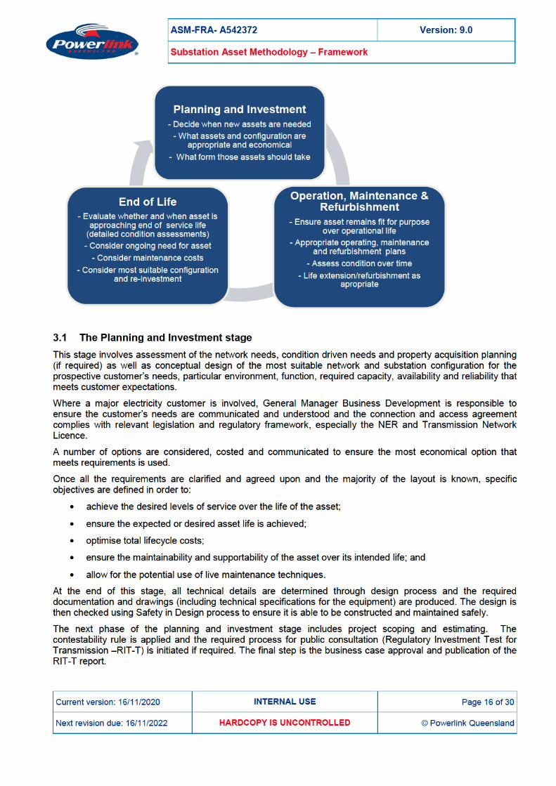
3. Lifecycle Management
Electricity transmission assets including high voltage substation equipment and related infrastructure are high cost assets with a relatively long expected operating life.
During the Planning and Investment phase it is important to influence design, configuration and topology aspects of the substation asset to provide a platform for achieving desired reliability, availability and maintainability at minimal investment and life cycle cost, whilst keeping flexibility to expand if needed being especially important during this period of significant energy transformation.
In order to achieve the best outcome for its stakeholders, Powerlink must consider the asset’s whole of life cost. Minimising this cost is the basis of Powerlink’s asset management approach and involves the following:
• optimisation of the standards, configurations and the design process;
• consideration of the asset’s expected operating life; and
• the effective management of the asset’s lifecycle through targeted maintenance, refurbishment, modifications, life extension, replacement and disposal activities.
This approach is often referred to as Lifecycle Management and includes three main stages as defined by Asset Management Strategy:
ASM-FRA- A542372 Version: 9.0
Substation Asset Methodology – Framework
Current version: 16/11/2020 INTERNAL USE Page 17 of 30
Next revision due: 16/11/2022 HARDCOPY IS UNCONTROLLED © Powerlink Queensland
This is followed by the production of final design, determination of procurement methods, contracts, project and construction management, variations, testing, commissioning, production of "as per built" documentation, recording all required substation plant data and financial asset values in the computerised maintenance management system/asset register (Powerlink utilises SAP for both), and final handover of the built substation to the relevant maintenance service provider, asset management group and network operations.
3.2 Operation, Maintenance and Refurbishment stage Geographically, Powerlink operates a long, skinny transmission system, most of which hugs the coast of Queensland. The energy transformation is driving the change of transmission network extending it inland and reducing what previously has been a significant separation between load and generation centres. One historical fact about Queensland transmission network remains and that is there is little meshing within the network. Outages are even more difficult to obtain due to the impact of energy transformation on network stability and reduced network strength and must be planned and coordinated carefully to minimise their number and duration.
The Operation, Maintenance and Refurbishment stage is the longest stage of all. For the majority of substation assets this stage is typically expected to last around 40 years, although where customers specify a requirement for connections over a shorter period, this can be achieved by application of modified standards.
It starts with final handover ensuring that all relevant substation plant data are readily available, all relevant training and operation and maintenance documentation is provided to maintenance service providers, and that all routine maintenance plans are established. This is the responsibility of General Manager Technical and Network Solutions. In addition, it is the responsibility of Manager Asset Strategies that all maintenance and operating policies and procedures are in place to ensure substations are operated within technical parameters and perform as per initial requirements.
Due to the different failure modes in some types of substation equipment and associated safety risk increase, it may not be possible to achieve 40 years service life for all substation equipment. It is the responsibility of the Manager Asset Strategies to assess the condition and initiate life extension, refurbishment or replacement project for such substation equipment in a timely manner. The strategy is to replace with alternative equipment that has reduced safety consequences, if possible and commercially viable.
In contrast substation equipment in some operating context can be fully operational and safe to operate in excess of 40 years. To achieve this, both their condition and performance have to be monitored with relevant activities undertaken to ensure their optimum performance. Such activities may include, but are not limited to routine maintenance, condition based maintenance, emergency and deferred corrective maintenance, partial component replacement and/or life extension, equipment modifications, desktop and detailed condition assessments, technical investigations, review of asset performance, reporting, audits and benchmarking.
Sometimes the maintenance activities identify a need for improvement of substation plant which can drive innovation. The drivers for this can be related to work, health and safety, legislative or other compliance requirements or to ensure optimum service life expectancy. These can be made through refurbishment projects and involves any activities required to bring them up to present day standards or to meet improved safety or operational requirements. Examples of such activities are:
• installation of improved physical security measures;
• installation of noise suppression systems to meet environmental standards, where appropriate;
• upgrade of substation earthing systems;
• replacement of plant items containing PCB or asbestos to meet WH&S requirements;
• installation of improved oil separation systems to meet council or state environmental requirements;
• replacement of power transformer bushings to reduce safety risk and potentially extend life of power transformer;
• replacement of circuit breaker operating mechanisms or their parts to achieve expected service life; and
• replacement of hybrid modules disconnector/earth switch drives.
ASM-FRA- A542372 Version: 9.0
Substation Asset Methodology – Framework
Current version: 16/11/2020 INTERNAL USE Page 18 of 30
Next revision due: 16/11/2022 HARDCOPY IS UNCONTROLLED © Powerlink Queensland
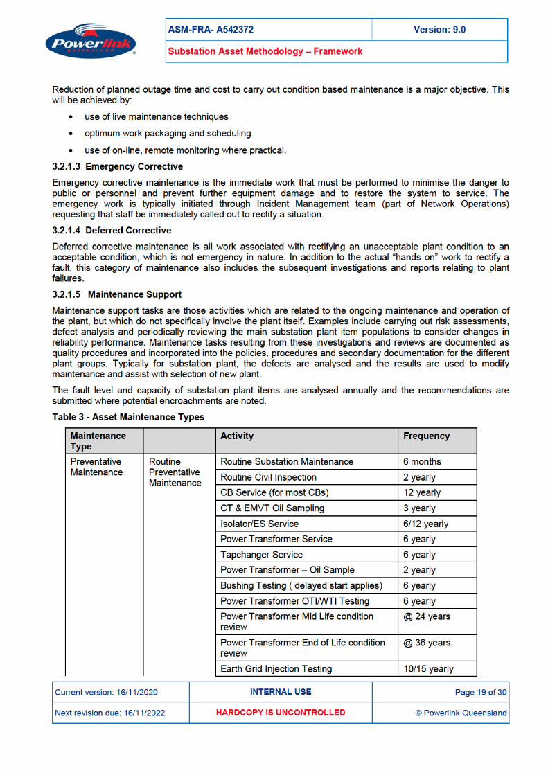
3.2.1 Maintenance Maintenance strategy for substation plant is established using a Reliability-Centred Maintenance (RCM) model.
RCM provides a rigorous and verifiable analysis framework for identifying only those maintenance tasks that are applicable and effective in managing possible failures. RCM analyses are undertaken by facilitated review teams of technical experts and field personnel with the greatest knowledge of the Network Assets being analysed. RCM also identifies those failures that cannot be dealt with effectively by maintenance alone, and thus require other approaches to deal with them. This ensures that only practical, achievable and effective maintenance tasks are adopted. These are verified and checked periodically through various benchmarking with other electricity transmission authorities In Australia and overseas.
Prior to, or at the commissioning of a new type of substation plant item, a formalised Reliability-Centred Maintenance analysis is organised to analyse potential failure modes and countermeasures resulting in the development of the appropriate routine maintenance regime for that type of plant item.
Substation Plant consists of a mixture of static and moving plant of varying sophistication and complexity. Typical substation plant failure modes relate to their inherent design characteristics, surrounding environment, applied electrical load and stress and duty cycle.
Powerlink’s strategy for substation plant maintenance is based on an RCM applied philosophy of non-invasive local and remote performance monitoring and condition assessment by condition monitoring and testing, with invasive maintenance only being performed on a scheduled basis where there is no practical alternative.
Wherever it is cost effective to do so, remote performance and condition assessment of substation plant is undertaken.
In addition from time to time value driven maintenance (VDM) process is used to identify routine maintenance tasks that may need to be reviewed to ensure they provide value for money.
3.2.1.1 Routine scheduled The nature of failure modes of substation plant means that the RCM developed maintenance strategy is primarily based on the assessment of condition using visual inspection, on line condition monitoring and testing. There is a limited amount of time or duty based scheduled restoration or discard tasks. Various levels of routine scheduled maintenance are applied as part of this strategy. They are:
3.2.1.1.1 Routine Substation Maintenance (RSM) RSM is a non-invasive, visual inspection of all substation plant in a location, conducted on a regular basis as specified by the maintenance specification. RSM does not require network outages.
3.2.1.1.2 Service Level Maintenance Service Level Maintenance is conducted on specified plant in accordance with the appropriate maintenance specification, and generally consists of more detailed and focused non-invasive condition monitoring and testing tasks, such as contact resistance checks, bushing capacitance measurement, measurement of circuit breaker open and close times. Where practical, service level maintenance is carried out on live equipment however planned outages are required on most equipment.
In addition to the service level maintenance, oil and gas samples are taken periodically and whilst for power transformers oil samples the outage is not required, the outages are required for samples to be taken from instrument transformers.
3.2.1.1.3 Overhaul Overhauls are conducted on specified plant in accordance with the appropriate maintenance specification. Overhauls are generally invasive requiring a planned outage.
3.2.1.2 Condition based Continuous performance monitoring, routine scheduled maintenance, visual inspection, condition monitoring, and testing are all used to detect deterioration of condition or degradation of performance of substation plant that will, if allowed to continue, result in equipment/asset failure sometime in the future. Condition Based Maintenance restores the condition or performance of the asset to an acceptable level before failure occurs.

ASM-FRA- A542372 Version: 9.0
Substation Asset Methodology – Framework
Current version: 16/11/2020 INTERNAL USE Page 21 of 30
Next revision due: 16/11/2022 HARDCOPY IS UNCONTROLLED © Powerlink Queensland
3.3 End of Life End of Life involves the actions required on assets and plant that have reached a level of unacceptable risk if they were to remain energised. These actions can be categorised as plans for timely:
• De-energisation; • Seeking non network solutions; • Replacement; or • Removal and disposal of an asset if it is no longer required for successful operation of the network.
It is the responsibility of Substation Strategies Team Leader to ensure the condition is monitored and end of service life of high voltage plant is predicted based on recommendations and information generated through desktop and detailed condition assessment reports.
4. Asset Management Drivers
Substation plant assets represent a significant percentage of network assets within Powerlink. Due to the nature of their design and construction they have a typical service life of 40 years.
It is critical to manage these assets in such a way as to achieve not only the optimum operating life but to do so at the minimal lifecycle cost whilst maintaining required reliability and availability of electricity supply, safe environment for personnel and public and meet all compliance requirements. This can only be achieved by setting appropriate asset management strategies from the beginning of each substation's lifecycle. Powerlink assets live in a dynamic environment that needs to take into account a range of internal and external factors, and respond in an appropriate and timely fashion.
Internal Influencing Factors
• Condition assessments & changes in the equipment health indices. • Technical investigations and research. • Corporate Risk Framework. • Data modelling and reporting. • Fault and defect statistical data. • Substation plant ratings. • Compliance issues. • Changes of work methods. • Changes in the work force. • Feedback from maintenance. • Continuous improvement process. • Research and development and innovation.
External Influencing Factors
• Demand and energy consumption. • Changes in electricity generation sector. • Innovation and technology. • Environment and duty. • Emerging issues. • Change of legislation and/or engineering standards. • Change of customer requirements. • Change of regulatory environment. • Obsolescence (lack of availability of spare parts and/or technical support).
ASM-FRA- A542372 Version: 9.0
Substation Asset Methodology – Framework
Current version: 16/11/2020 INTERNAL USE Page 22 of 30
Next revision due: 16/11/2022 HARDCOPY IS UNCONTROLLED © Powerlink Queensland
• Changes in electricity distribution sector.
4.1 Condition Assessment Most Powerlink substation plant assets deteriorate through a mixture of deterioration processes as a result of environmental conditions, wear out, electrical stress, exposure to faults and network loading. The end-of-life of a substation asset is determined by its performance (measured through availability, corrective maintenance and condition based maintenance cost trend) and the condition of its components. Typically, the asset is declared at the end of its life when performance is significantly deteriorated and major components are deteriorated, or the safety of workers or the public is assessed as compromised based on the SFAIRP principle. A number of substation assets fail while in service typically as a result of random or inherited design failures, or random network conditions leading to insulation overstress.
Powerlink’s’ asset management system aims to minimise the number of failures in service. Typically, Powerlink substation assets are expected to last for 40 years, however this can vary between items depending on design, construction, installation, maintenance, duty and environmental conditions. For example most modern transmission circuit breakers are expected to last up to 40 years although this is dependent on technology. Circuit breakers that switch generators or reactive plant are operated more frequently and may require major refurbishment or replacement after half the nominal life. They often reach the maximum rated number of operations after 25-30 years of service.
Substation equipment condition is monitored using equipment condition scores known as health indices. Improved IT systems enable the live update of these. They feed automatic calculations for safety and network risks driven by the condition of substation plant. Based on these and additional information provided by maintenance service providers as well as availability and forced outages reports, desktop and detailed condition assessments are initiated. The condition assessment report provides an overview of defective and deteriorated items and may initiate further investigation and analysis of the data to determine the level of deterioration. It provides estimated remaining service life for each asset, equipment and/or component. Where possible the holistic condition of all assets at a substation is assessed collectively to arrive at the optimum solution for refurbishment, retirement or reinvestment for the site.
4.1.1 Condition Assessment Process For the purposes of condition assessment, substations can be viewed as a hierarchical construction of plant and equipment items. The items combine into functional groups that make up individual financial assets and the assets combine together to comprise a substation.
Powerlink applies condition assessments to assess the risks arising from the deteriorated condition of the substation plant from a range of perspectives including impact on safety, network operations, business strategy, finance and contractual obligations, impact on major stakeholders, project costs, and environmental and cultural heritage. Condition assessments combined with planning reports are also used as a basis for the development of options for non-network solutions, refurbishment or reinvestment where this is considered necessary. Difficulties associated with obtaining access to operational assets and associated mobilisation and construction site establishment costs may results in Powerlink carrying out replacement or major refurbishment projects at the asset level or even at a substation level. The economic analysis indicates that the replacement of the individual plant items in a piecemeal fashion may not always result in the optimum cost savings. For this reason it is important to consider all options for non-network solution, replacement or major refurbishment. The substation plant methodology includes condition assessment activities at the lowest possible level to enable this to occur. These activities are initiated and managed by Powerlink’s Substation Strategies team.
4.1.2 Condition Data 4.1.2.1 Plant Item Level Plant items such as circuit breakers, instrument transformers, isolators, earth switches, power transformers, reactive power plant (capacitors, reactors and SVCs), busbars and substation structures are the building blocks from which the substation is constructed. In addition there are many elements that comprise substation infrastructure such as substation earthing system, buildings, fire protection systems, roads, switchyard lighting, oil separation systems, noise enclosures, substation auxiliary supply, and substation security systems. The condition of these items is monitored during routine inspection and servicing as applicable. Defects are reported
ASM-FRA- A542372 Version: 9.0
Substation Asset Methodology – Framework
Current version: 16/11/2020 INTERNAL USE Page 23 of 30
Next revision due: 16/11/2022 HARDCOPY IS UNCONTROLLED © Powerlink Queensland
and recorded in SAP and the data is analysed using equipment health indices. This information is used to identify the need for detailed or desktop condition assessments and to identify and manage corrective and condition based maintenance programs. Where common defects are noted for a population of items, the information can be used to trigger operational refurbishment projects.
Condition information for primary plant items can include details on:
• fluid containment and grades of metal corrosion from visual inspection; • contact and current carrying path resistances and localised hot spot temperatures; • insulation resistance, capacitance and dielectric information for graded insulation systems; • dissolved gas analysis and oil quality information from oil-insulated plant; • moisture and contaminant information from SF6 insulated plant; • operations counts and hour run meters from mechanical switching devices; • electrical partial discharge measurements to detect insulation breakdown; • performance tests undertaken during service such as circuit breaker travel and operating time
measurements; • details of failed and replaced components; • insulating paper condition expressed as degree of polymerisation (DP) value; • number of initiated alarms; and • condition of civil structural components.
Determination of the complete condition of a plant item requires analysis of the appropriate parameters, weighting each result in a manner determined by the importance of the parameter and then combining the information to give a total result for each item. This provides a holistic representation of the condition or health of the item and provides a means to rank the condition of each item within the population. Powerlink utilises a health index methodology for this.
Health index is a consistent and logical means of combining relatively complex and diverse condition information about a specific equipment item. It gives a total score between 1 and 10 representing the item’s overall condition relative to that of the other items within the specific equipment population. Application of health index requires engineering expertise, statistical data and knowledge of replacement methods. To be of use in assessing future actions, the health index profile for an equipment type needs to bear a relationship with the probability of failure or hazard rate for equipment items, particularly those at the deteriorated end of the curve. This requires calibration with real failure data. In addition the algorithm is designed to provide a predictive assessment of how the health index profile will change in the future as an item’s condition goes through the process of further deterioration.
Health index provides a means to identify items that are performing satisfactorily as well as those that are performing poorly enabling resources to focus on those items that should be targeted for detailed condition assessment now, or in the near future to form a basis to plan their repair, refurbishment, reinvestment, de-energisation or retirement. Health index information is used to identify outliers for potential corrective and condition based maintenance activities.
4.1.3 Engineering Data Engineering information relating to the designed performance of the asset is collated. This could include information on structure, electrical ratings and capacity, and layout design. It also includes consideration of an individual item’s performance in the service environment, design vulnerabilities and assumptions, historical performance of similar assets and industry experience as well as any change in standards or legislation. This activity is undertaken by strategies and standards groups.
4.1.4 Condition Assessment Report The Condition Assessment Report for substation plant assets is the product of the Condition Assessment and Engineering Data investigations. The Condition Assessment Report will take the engineering, loading and condition data and apply analytical techniques, modelling, expected future performance criteria, based on probability of failure curves and probabilistic evaluation to determine the decision criteria for the risk
ASM-FRA- A542372 Version: 9.0
Substation Asset Methodology – Framework
Current version: 16/11/2020 INTERNAL USE Page 24 of 30
Next revision due: 16/11/2022 HARDCOPY IS UNCONTROLLED © Powerlink Queensland
assessment. This activity will be undertaken by Powerlink strategies engineers, planning engineers and connection and development managers (regarding future performance requirements) and design groups in consultation with the respective maintenance service provider for the asset.
The objectives of the Condition Assessment Report are to:
• determine and document the condition of the equipment or assets with respect to the decision criteria;
• determine estimated remaining service life for each equipment and component of substation infrastructure; and
• provide an input for: o life extension; o corrective and condition based maintenance recommendations; o high level scope of work for refurbishment; or o replacement, energisation or retirement of the equipment, assets or substation.
4.2 Technical Investigations and Research To support substation asset strategies, technical specialists are engaged from time to time to assist with investigations and recommend and review technical solutions. Investigations can be initiated by a task request for internal specialists or through a commercial arrangement with a subcontractor or industry specialist. These activities include research into new technologies (non-conventional instrument transformers for example), providing design input for installation of semi pantograph disconnectors, ultimate substation layouts, investigations of various life extension methods, investigation of emerging issues (such as copper and silver corrosive sulphur phenomenon) and any other innovative ways of using new or existing technology.
The Senior Substation Strategy Engineer will initiate technical investigations and research projects as required.
4.3 Innovation, Technology and Emerging Issues 4.3.1 Climate Change Adaptation Climate change adaptation dictates that the resilience and durability of the transmission network needs to be assessed and its susceptibility to issues that may arise as a result of changes in climatic conditions. Climate change and its resulting impacts have the potential to shorten the life and reduce the capability of substation plant. The impact of the different physical parameters from climate change on individual substation items needs to be assessed to understand the potential risk to assets and the network.
Projected impacts of climate change in Queensland are:
• increase in number of days with temperatures over 350C;
• increase in number of severe storm events and flash flooding;
• more frequent and severe droughts and increased fire risk; and
• decrease of days with certain wind speeds.
4.3.2 Connection of renewable energy sources One area of change due to technology and production improvements as well as environmental pressures is the increase of renewable energy sources connected to the electricity grid. The impact of change in generation mix on the transmission network is significant and requires careful assessment and analysis. One of the outcomes is the weak and not very stable network, increased number of substations especially inland and increased complexity in managing assets with varying customised substation layouts and varying expected service lives. In addition there is a requirement to manage multiple customers which are new to the Australian electricity sector.
ASM-FRA- A542372 Version: 9.0
Substation Asset Methodology – Framework
Current version: 16/11/2020 INTERNAL USE Page 25 of 30
Next revision due: 16/11/2022 HARDCOPY IS UNCONTROLLED © Powerlink Queensland
4.3.3 Internet of Things (Substations Digitalisation) There is an ever-increasing number of substation equipment that are monitored and automated through the use of computing devices which have the ability to be connected via digital networks.
This technology brings many benefits for the management of assets such as:
• real time condition data;
• self-monitoring;
• remote access and improved remote operation of the substation equipment;
• better data analysis;
• increased data and therefore increased accuracy in determination of end of service life; and
• reduced exposure of workers to potential safety risks
It also raises and increases some other risks such as:
• compromised cyber security;
• change of required skills;
• loss of rapid intervention skills and technical knowledge;
• risks associated with loss of communications; and
• shorter expected service life of these devices when installed outdoor
Powerlink is monitoring and actively influencing these technological developments and preparing for their full implementation in the future when appropriate driven communication protocols are matured.
4.3.4 Use of Unmanned Aerial Vehicles (UAV) Powerlink is currently at early stage of using UAV inspection techniques inside substations. The benefit is potential efficiency in utilising UAV’s in Powerlink substations through increased number of angles of inspections, emergency management and identification of early signs of deterioration without a need for outages and working at heights. Powerlink is doing this with fulfilment of its obligations under Work Health and Safety legislation to ensure that UAV’s do not pose a risk to staff, equipment and members of the public.
5. Emergency Response and Network Security
5.1 Emergency Response Cyclones and natural disasters are a part of the Queensland climate. While substation assets have performed well during cyclones and other natural disasters, specific measures are taken to improve resilience in these events such as:
• appropriate backup for substation AC supplies in cyclonic areas including increased fuel supply for diesel generators and increased number of portable plug in diesel generators;
• appropriate spare levels;
• arrangements to share spares with other Transmission Network Service Providers where applicable;
• contingency plans in place where required;
• flood monitoring measures; and
• increased co-operation and utilisation of Bureau of Meteorology services and data.
ASM-FRA- A542372 Version: 9.0
Substation Asset Methodology – Framework
Current version: 16/11/2020 INTERNAL USE Page 26 of 30
Next revision due: 16/11/2022 HARDCOPY IS UNCONTROLLED © Powerlink Queensland
5.2 Network Security Substation security needs to take into account the different levels of threat posed to an asset of this type and threats posed by the asset of this type to the public.
The transmission network is part of National Critical Infrastructure and higher levels of security measures are required at critical substations to meet minimum standards of overall security. Other levels of threat include theft and vandalism. Substations have become a target for theft and vandalism due to the presence of attractive materials (e.g. prolific use of copper), remoteness and isolation, and low occupancy of Powerlink personnel. Apart from causing financial loss, such thefts constitute electrical safety incidents and are reportable to Electrical Safety Office.
Powerlink continues to assess requirements and accordingly invest in the security of our critical transmission assets with a focus on improving deterrent and especially detection measures at higher risk sites.
The substations will remain accessible only to authorised and competent personnel and escorted visitors.
6. Supporting Activities
6.1 Risk Management To successfully manage Powerlink’s substation assets, it is necessary to identify and manage a range of risks, including those not directly related to the performance of the asset. These are analysed using the corporate risk framework. There is a range of risk mitigation and risk reduction measures employed such as condition based oil, SF6 and water discharge samples, restricted access zones, increased frequency of inspection and service, PD scanning and innovative work methods such as live work, development of contingency plans and selective component replacement. The outcome is to provide a structured approach for the identification, assessment and treatment of hazards ensuring the management of risks to a level that is deemed to meet criteria of being So Far As Reasonably Practicable (SFAIRP).
6.2 Project Handovers The construction of new substation assets, plant item replacement or life extension of assets involves the interaction of design, construction, project management, material acquisition, maintenance service providers, and strategies groups both within and external to Powerlink. The transition from the practical completion of a substation asset to becoming a maintainable and operational asset requires the recording and communication of critical information and related data about the asset.
The Project Handover process has been implemented to provide the conduit for transferring design and construction information between the Designers, Construction Contractor and the Maintenance Service Providers. It also provides an opportunity for co-operation between the Asset Strategy Group, Incident Management Groups, Construction Management, the Project Team and the Maintenance Service Providers to discuss the assets and the project handover process, and to ensure that opportunities for improvement are implemented through future projects and equipment strategies
6.3 Strategic Spares An annual review of substation plant strategic spares is performed to ensure that:
• the quality, quantity and location of spares are adequate and appropriate;
• the storage practices and facilities of spares are satisfactory to ensure component life span is not compromised as a result of incorrect or inadequate storage practices;
• adequate spares have been supplied for new assets and component changes; and
• the spares which are no longer required are identified and sold or otherwise disposed of.
In addition, the maintenance of strategic spares is organised and conducted at appropriate intervals.
ASM-FRA- A542372 Version: 9.0
Substation Asset Methodology – Framework
Current version: 16/11/2020 INTERNAL USE Page 27 of 30
Next revision due: 16/11/2022 HARDCOPY IS UNCONTROLLED © Powerlink Queensland
6.4 Technical Training Operation and Services Delivery (OSD) provides a strategy for the delivery of technical training to reinforce key concepts and strategies with service providers across the asset lifecycle. Technical training is initially delivered by plant manufacturers or their agents.
Powerlink has an obligation to ensure that training is available for Maintenance Service Providers so that they are competent to perform work on all transmission assets, including those newly introduced.
6.5 Documentation The Substation Strategies Team conveys asset management requirements through the Substation Asset Methodology framework and a number of asset management documents that are reviewed every two years and promote the development of documentation and field guides to ensure substation plant strategies remain relevant and are in accordance with good industry practice.
6.6 Strategic Linkages The Substation Strategies team develops and maintains strategic linkages internally within Powerlink and with the relevant stakeholders in order to ensure a seamless integration of network topography is maintained.
Alignment is maintained between Principal Maintenance Service Providers such as Energy Queensland and Operation & Service Delivery, to ensure consistency in the provision of maintenance services.
Channels of active communication are maintained with other Transmission Network Service Providers (TNSP) to facilitate emergency restoration activities, provide discussion forums for work delivery protocols such as live work and share information on the implementation of new technology and major plant statistical data.
The active participation with various international power research institutes (such as EPRI and CEATI) as well as participation in various CIGRE bodies of work ensures the strategy can be kept up to date with technology developments.
6.7 Benchmarking Powerlink participate in benchmarking with other worldwide located electricity entities through bi-annual data submission via ITOMS.
In addition RIN (Regulatory Information Notice) data are analysed and benchmarked with other TNSPs in Australia.
7. Health, Safety and Environment
The design and implementation of substation plant maintenance strategies incorporate Powerlink’s Health, Safety and Environment Policy. This includes the use of risk management processes to ensure the safety of workers, the safety of the public and the safety of plant and equipment. All major plant failures are investigated with recommendations provided and implemented.
Risk assessment processes are also used to identify and appropriately manage environmental risks such as:
• containment of PCBs in older equipment;
• containment of insulating oil in equipment such as transformers and circuit breakers;
• management of operational noise from substation plant;
• containment of SF6 in switchgear and instrument transformers;
• containment of hydrocarbon fuels such as diesel for generators;
• presence of asbestos in older buildings and equipment; and
• management of vegetation inside and outside substations.
ASM-FRA- A542372 Version: 9.0
Substation Asset Methodology – Framework
Current version: 16/11/2020 INTERNAL USE Page 28 of 30
Next revision due: 16/11/2022 HARDCOPY IS UNCONTROLLED © Powerlink Queensland
8. Forward Planning
A ten year forward plan is prepared per regional area and network segments basis, outlining the projects by type, location and expected completion date.
All routine maintenance plans are entered into SAP by the outage group. These are combined with project outages and assessed 12 months in advance to minimise requirements for outages and ensure network security is maintained. The other condition based and corrective maintenance activities are scheduled along with these as much as possible.
In addition Powerlink has developed and worked with local manufacturers to construct a mobile substation bay (installed on transportable skids) that can be used to temporarily connect feeders to the busbars in 132 kV substations reducing required duration of outages for in situ replacement projects.

ASM-FRA- A542372 Version: 9.0
Substation Asset Methodology – Framework
Current version: 16/11/2020 INTERNAL USE Page 30 of 30
Next revision due: 16/11/2022 HARDCOPY IS UNCONTROLLED © Powerlink Queensland
Appendix A List of Documentation to be provided at Project Handover
The minimum maintenance documentation shall include the following:
• Locality plan
• Project Scope Report
• Project Management Plan
• Project Drawing Index
• Geotechnical Report
• Project notes and specification
• Design specification
• Design Reports
• Equipment specifications and copies of equipment purchase orders
• Equipment O&M Manuals
• All Civil Design drawings and structural calculations
• All Electrical Design drawings (General arrangement, section drawings, etc.)
• Project Environmental Management Plan
• Project Environmental Work Plans
• Project Weed Management Plan
• Environmental Close Out Reports
• Environmental Flora & Fauna
• Copies of equipment nameplates
• List of all design drawings
• Single line diagram
• Substation layout drawings
• Evidence of all SAP data being populated
• Construction photos
• List of defects identified during project activities
• Copies of all O&M manuals from equipment manufacturers
• Copies of all factory and commissioning test results and reports
• Earth grid design reports and grid injection test results
• Ratings report