Embed Size (px)
Citation preview

Journal of Multidisciplinary Engineering Science and Technology (JMEST)
ISSN: 3159-0040
Vol. 2 Issue 10, October - 2015
www.jmest.org
JMESTN42351003 2700
The Role Of Modeling, Simulation And Analysis Stage In Mechatronics Systems Design
Education
Farhan A. Salem 1,2
1Mechatronics engineering program, Dept. of Mechanical Engineering,
College of Engineering, Taif University, 888, Taif, Saudi Arabia. 2Alpha center for Engineering Studies and Technology Researches, Amman, Jordan.
Abstract—Mechatronics systems are designed with synergy and integration toward constrains like higher performance, speed, precision, efficiency, lower costs and functionality and operate with exceptional high levels of accuracy and speed despite adverse effects of system nonlinearities, uncertainties and disturbances, therefore, such constrains must be tested, verified, refined, ensured and met. In order to evaluate such concepts and others generated during the design process, without building and testing each one and take corresponding design decisions, Modeling, simulation and evaluation, play a critical role and considered as highly important during the design stages of a Mechatronic system. The primary challenge in modelling and simulation of Mechatronic systems lies in their multidisciplinary and crosses domain boundaries nature. This paper focuses on modelling, simulation, analysis and evaluation stage in Mechatronics design and development education oriented methodology, concepts, description, role, classification and applications are presented and discussed, and by means of examples-projects. The paper is intended to support engineering educators and help students in solving Mechatronics design and development tasks. A short review of scientific resources on modelling and simulation in Mechatronics are also presented.
Keywords—Mechatronics education, Design methodology, Modeling, Simulation, Analysis.
I. INTRODUCTION
The modern advances in information technology and decision making, as well as the synergetic integration of different fundamental engineering domains caused the engineering problems to get harder, broader and deeper. Problems are multidisciplinary and to solve them require a multidisciplinary engineering systems approach, such modern multidisciplinary systems are called Mechatronics systems[1-2].Mechatronics engineer is expected to design products with synergy and integration toward constrains like higher performance, speed, precision, efficiency, lower costs and functionality, also in order to evaluate such concepts and others generated during the design process, without building and testing each one, Mechatronics engineer must be skilled in the modeling, simulation,
analysis and control of dynamic systems and understand the key issues in hardware implementation[3]. due to different disciplines involved, the Mechatronics design process may become very complex, and correspondingly, engineering educators face daunting challenges. The key element in success of a Mechatronics engineering program, and correspondingly Mechatronics engineering graduates, is directly related to the applied structural design methodology. A guidelines for structural design methodology and tools for the development process of Mechatronic products, that can support educators and help students in solving Mechatronics design integrated tasks with their specific properties and can be applied in educational process is highly required, such guidelines for structural design methodology are proposed in [1-2], this methodology is developed, based on VDI 2206 guideline [5] and different industrial, scientific and educational resources including [4-20], and is proposed to fulfill Mechatronics optimal program requirements. The proposed methodology consists of a systematic specific simple and clear steps (depicted in diagram 1) that are easy to memorize, follow and aims to support engineering educators and help non experienced student or group of students to integrate gained multidisciplinary abilities and knowledge, in various stages in solving Mechatronics design integrated tasks. This paper extends writer's work [1-2] and focuses on Modeling, simulation, analysis and evaluation stage and corresponding concepts in Mechatronics design and development methodology, concepts, description, role, classification and applications are to be presented, explained and discussed, and by means of examples-projects. The papers is intended to support engineering educators and help students in solving Mechatronics design and development tasks, also, a review of scientific resources on modelling and simulation in Mechatronics are presented.
I.I MECHATRONICS SYSTEMS DESIGN APPROACH.
There are many definitions of Mechatronics, it can be defined as multidisciplinary concept, it is the synergistic integration of mechanical engineering, electric engineering, electronic systems, information technology, intelligent control system, and computer

Journal of Multidisciplinary Engineering Science and Technology (JMEST)
ISSN: 3159-0040
Vol. 2 Issue 10, October - 2015
www.jmest.org
JMESTN42351003 2701
hardware and software to manage complexity, uncertainty, and communication through the design and manufacture of products and processes from the very start of the design process, thus enabling complex decision making. Modern products are considered Mechatronics products, since, it is comprehensive mechanical systems with fully integrated electronics, intelligent control system and information technology. Such multidisciplinary and complex products, considering the top two drivers in industry today for improving development processes, that are shorter product-development schedules and increased customer demand for better performing products, demand another approach for efficient development. Mechatronic system design process addresses these challenges, it is a modern interdisciplinary design procedure, it is the concurrent selection, evaluation, integration, and optimization of the system and all its sub-systems and components as a whole and concurrently, all the design disciplines work in parallel and collaboratively throughout the design and development process to produce an overall optimal design– no after-thought add-ons allowed, this approach offers less constrains and shortened development, also allows the design engineers to provide feedback to each other about how their part of design is effect by others.
Integration refers to combining disparate data or systems so they work as one system. The integration within a Mechatronics system can be performed in two kinds, a) through the integration of components (hardware integration) and b) through the integration by information processing (software integration) based on advanced control function. The integration of components results from designing the Mechatronics system as an overall system, and embedding the sensor, actuators, and microcomputers into the mechanical process, the microcomputers can be integrated with actuators, the process, or sensor or be arranged at several places. Integrated sensors and microcomputers lead to smart sensors, and integrated actuators and microcomputers developed into smart actuators. For large systems bus connections will replace the many cable. Hence, there are several possibilities to build up an integrated overall system by proper integration of the hardware. Synergy from the Greek word synergeia meaning "working together“ and refers to the creation of a whole final products that is better than the simple sum of its parts, an integrated and concurrent design should result in a better product than one obtained through an uncoupled or sequential design [2][21]. synergy can be generated by the right combination of parameters.

Journal of Multidisciplinary Engineering Science and Technology (JMEST)
ISSN: 3159-0040
Vol. 2 Issue 10, October - 2015
www.jmest.org
JMESTN42351003 2702
Figure 1 Systematic guideline steps for Mechatronics systems design education-oriented methodology
Pre-Study Process (The problem statement ) :(It is the process of understanding what the problem is, its goals and functions , and to state it in clear
terms. Done by identification, gathering and analysis as much as possible information about) :
Aesthetics: if pleasing elegant design is required, color, shape, form and texture to be specified
The problem statement in clear terms : based on up steps, description of what is the problem? the goal? the top-level functions, and/or state the problem in terms of the deficiency that must be ameliorated user and system requirements,
b
1
Conceptual Design, functional specifications and their structure.
(Consider the system as a whole, building a description of it in terms of an interdisciplinary set of integrated general ideas and concepts, conceptual design is usually evolve from problem statement; user and system requirements)
2
Identification, description and analysis of the required system ,what is the system?, it's overall function? ,
sub-functions?, behavior/performance?, how it looks like?. a
Morphological analysis; Build Morphological table, suggest solutions for functions, evaluate the best solution. b
c
Parallel (concurrent) selection, evaluation, synergetic integration and optimization of the system and all its
sub-systems as a whole and concurrently, all the design disciplines work in parallel and collaboratively
throughout the design and development process to produce an overall optimal design– no after-thought
add-ons allowed. 3
Parallel (concurrent) optimal selection, evaluation, synergetic integration and optimization of the system
and all its modules-sub-systems and all components as a whole and concurrently throughout the design
and development process, with respect to the realization of the design specifications and requirements
Mechanical sub-system; the design of all mechanical aspects in full details to meet the requirements; structure Eements, Mechanisms, Dimensions, Materials, Properties, Parameters ...(CAD/CAM tools ....)
Electric & Electronics; Interconnections, signal conditioning, interfacing.
Divided the system into realizable modules ( subsystems).a
Sensors subsystem Actuators subsystemControl unit sub-system Control algorithm and design
Human–machine interaction field
Develop system's complete and detailed block diagram layout
Modeling, simulation ,analysis and evaluating:
The main goal; early identifying system level problems (to verify main and sub-functions and to test and analyze sub-systems and the whole system model), and ensuring that all design requirements are met (satisfied)
4
Two types of modeling process ; Analytical modeling; Represent the sub-systems and whole system
using mathematical equations suitable for computer simulation ( e.g. MATLAB, Labviev). Physical
(Experimental ) modeling; based on obtained measurements from the system
b
b
c
Prototyping, testing, evaluation and optimization
To take into account the unmodeled errors and enhance precision, performance and gather early user feedback5
Virtual Prototype: 2-3D model of a product presented in a virtual (PC) environment with, ideally, all
information and properties included, used to examine, manipulate, and test the form, fit, motion, logistics,
and human factors of conceptual designs on a computer monitor,
a
Physical Prototype: system integration to ensure that subsystems, components and whole system work
together under operating condition
Manufacturing and Commercialization6 Support, Service and Market feedback Analysis 7
simul
tane
ous s
yner
gisti
c in
tegr
atio
n an
d op
timiza
tion
of th
e sys
tem
and
all
its su
bsys
tem
s as a
who
le, n
o af
ter-
thou
ght a
dd-o
ns a
llow
ed--
Itera
te fo
rwar
d an
d ba
ckw
ard
to fu
lfill
requ
irem
ents
Target user, market and user interests/needs/requirements identification and analysis; (build user
requirements table)
Build requirements analysis table; fixed and soft requirements, description and types
Create detailed functional specifications.
Built system functional model (function box, Sequence or Hierarchy ), depicting the flow of (information,
Energy or Material) between the system’s components
Build preliminarysystem block diagram and layout of main components.
Identify system’s preliminary necessary structure ( e.g. mechanical, electric, control….),
A preliminary economic analysis;feasibility study , cost-benefit evaluation d
Designing system as a whole, serve as methodological basis for Mechatronic Systems development
Prototype development may be carried out in the following two forms
Integration refers to combining disparate data or systems so they work as one system. The integration
can be performed in two kinds: The integration of components (hardware integration), results fromdesigning the mechatronics system as an overall system and embedding (placement ) the sensors,actuators, and microcomputers into the mechanical process. The integration by information processing
(software integration) is based on advanced control function
d
A preliminary ideas about mechanical, electric problems and the necessary sensors, actuators, interfaces.
Synergy can be generated by the right combination /selection of proper parameters that is, the final
product can be better than just the sum of its parts.c
a
Break down the overall function/system into subfunction/subsystems; what are major subsystems/components? what
are subsystem’s/components' functions? how components interact ?and how they should be connected?
Generate preliminary decisions about the dominant mechanical properties, (e.g. matrials, sizing, volume,
DOF, joints types)
Subsystems models; in open and closed loop
aModeling process ; Verifying sub-functions and testing sub-systems, consists of two levels:
Overall system model; the verified sub-functions and tested sub-systems are integrated in one overall
system model interacting similar to real situation is checked
Simulation process ; is used to decide on the design specifications of the mechatronic system in terms of
specification of requirements. simulation divided into three parts: Mechanical simulation; To test the
kinematics and dynamics variables. System simulation; To test the system’s response to different inputs
in both open and closed loop. Electronic simulation; To test circuits functionality and compatibility
System requirements/specifications identification, definition and analysis; functional, Performance
and environmental and non-functional requirements.

Journal of Multidisciplinary Engineering Science and Technology (JMEST)
ISSN: 3159-0040
Vol. 2 Issue 10, October - 2015
www.jmest.org
JMESTN42351003 2703
II. MODELING, SIMULATION, ANALYSIS AND
EVALUATION.
Modeling, simulation, analysis and evaluation, play a critical role during the design stages of a Mechatronic system, the primary challenge in modeling and simulation of Mechatronic systems lies in their multi-domain nature, consisting of many different interconnected, interdisciplinary, integrated subsystems (and components such as, sensors, actuators, interfaces and mechanical geometry), modeling and simulation are multidisciplinary and crosses domain boundaries. In evaluating concepts, a modeling-simulation-and-analysis approach must replace any design-build-and-test approach, due to this, the key essential characteristics of a Mechatronics engineer and success in Mechatronics design, are a balance between two skills; Modeling/Analysis skills and Experimentation/Hardware implementation skills [1-3]. The main goal of Modeling, simulation and evaluation in Mechatronics design are; to support important design decisions by early identifying system level problems (to verify sub-functions and test sub-systems), and ensuring that all design requirements are met. Mechatronics design approach challenge conventional sequential design approach, by connecting machine design-test tools and creating a virtual machine prototype before designing the physical machine, to take all advantages that can result from an integrated design, this approach offers less constrains and shortened development, also allows the design engineers to provide feedback to each other about how their part of design is effect by others [1,2,9].
II.I CONCEPTS, DESCRIPTION, ROLE, CLASSIFICATION
AND APPLICATIONS
Referring to VDI 2206 design guidelines[5], four types of models are usually given for Mechatronic systems; namely topologic, physic, mathematic and numeric models [5]. A short introduction to these models and corresponding concepts in Mechatronics system design are followed next, later explained by examples. A model is a simplified representation of a system at some particular point in time or space intended to promote understanding of the real system. Modeling is the construction process of physical, conceptual or mathematical simulations of the real world. Mathematical Modeling: A process of representing the behavior of a real system by a collection of mathematical equations and/or logic, any modeling task requires the formulation of mathematical models suitable for computer simulation or solution. Topological modeling (Figure 2(b)): a mathematical approach that allows to structure data based on the principles of feature adjacency and feature connectivity (describes and reflects interlinks, the function-performing elements, basically the relative position between each component, without considering the physics behind), Topology of mechanical elements could be presented in various ways (e.g. graphs, free-body diagrams, tree-structure)
and essentially determines the kinematics of Mechatronic systems, Based on topology descriptions, a physical model is created and describes system properties in system adapted variables – e.g. masses and length for mechanical systems [4,23]. Physical model; One that physically represents an object (figure 2(b)), may be applied to understand the type of forces being acting and applied. Simulation is the process of solving the model i.e. solving mathematical equations and/or logic equations, simulation generally refers to a computerized version of the model which is run over time to study the implications of the defined interactions. In order to simulate a Mechatronic system, a multi-domain simulation environment is required. Multi-domain simulation could be achieved in different ways: a more traditional way is to use a general-purpose solver to simulate each subsystem and the whole integrated system, other way, called co-simulation, [26]. Co-simulation is to use different communicating solvers, to simulate each subsystem and whole system. It is a test software tool, used in order to validate the design choices and to develop the model on gradually decreasing levels of abstraction. Hardware-in-the-Loop simulation (HILS) is a technique that is used in the development and test of complex process systems and real-time embedded systems. It differs from pure real-time simulation by the addition of a real component in the loop via their electrical interfaces to a simulator, which reproduces the behavior of the real time environment; this component may be an electronic control unit or a real engine. The hardware-in-the-loop simulation testing provides the designer with reassurance that any assumptions made on the plant model were correct, if any assumptions were incorrect, however, the designer has the opportunity to optimize the design [24]. Various kinds of HILS can be realized, simulation of electronics, mechanics, sensors and actuators. Optimization is to obtain maximum benefits, from the given resources under the given constraints, the achievement of optimal performance for the required system performance specifications. Unmodeled errors, it is usually very difficult to build exact mathematical model for complex Mechatronics systems including all components. However, there is no single model which can ever flawlessly reproduce reality, there will always be errors called as unmodeled errors between behavior of a product model and the actual product. These unmodeled errors are the reason why there are so many model-based designs failed when deployed to the product. In order to take into account the unmodeled errors in the design process, the Mechatronics design approach includes virtual and physical prototyping phase. Prototyping is putting together a working model, serves to provide specifications for a real, working system rather than a theoretical one, it is believed to reduce project risks and cost. Modeling, simulation, analysis and evaluation processes in Mechatronics design consists of two levels; subsystems models (e.g. mechanical, electrical and electronic components, plant-dynamics,
Journal of Multidisciplinary Engineering Science and Technology (JMEST)
ISSN: 3159-0040
Vol. 2 Issue 10, October - 2015
www.jmest.org
JMESTN42351003 2704
inertias, energy flow, gears, interfaces, sensors, actuators, control) and overall system model with various sub-system models interacting similar to real situation, all engineering subsystems should be included in overall system model. There are two types of modeling process; a) Analytical modeling: (models can be obtained by either a theoretical approach based on physical laws), It is the process of representing the system using mathematical equations, suitable for computer simulation and used to describe changes in a system, analytical models are used to assist in systems analysis; calculations and predictions and plays a critical role during the design stages of a Mechatronic system. For all but the simplest systems, the performance aspects of components (such as sensors, actuators, and mechanical geometry) and their effect on system performance can only be evaluated by simulation [6]. b) Physical (Experimental) modeling: models can be obtained experimental approach based on obtained measurements from the system. Once models are available, simulation is used to decide on the design specifications of the whole Mechatronic system, based on the specification of requirements, the performance aspects of subsystems (and components) and their effect on system performance and test circuits functionality and compatibility, can only be evaluated by simulation[24] . The simulation can be divided into three parts: mechanical, electronic and system simulation; Mechanical simulation; used to test the kinematics and dynamics variables. System simulation; to test the system‟s response to different inputs in both open and closed loop, where control system (laws) design involves formulation of reasonably accurate models of the plant to be controlled, designing control laws based on the derived models and simulating the designed control laws using available simulation tools e.g ProEngineer and Solid-Works, MATLAB/Simulink, Labview. The subsystem model parameters should be determined based on the designed mechanical components and the selected actuators and sensors. The designer has the freedom to modify these values, increase the number of inputs/outputs used and include non-linearities in the subsequent design iterations [26]. Electronic simulation; To test circuits functionality and compatibility and evaluate the selection and design of interconnections, signal conditioning, and interfacing circuits, including; Drive-circuits ( e.g. relays, MOSFETs, L93DIC, transistors,), signals ( e.g. control signal, PWM signal), programming of control unit (e.g. Microcontroller), sensors, motor position-speed, the overall system or any such subsystem can be simulated using different computer software tools e.g. Saber, ISIS-Proteus and MATLAB. Commercial software tools available to design, model and simulate Mechatronic systems, that allow the stydy and analysis of components interaction and variation in
design include MATLAB/Simulink, labview, Scilab/Scicos, Ptolemy, JMathLib [19] , ADAMS, CAE tools, 3D-CAD softwares Pro/Engineer, CATIA, AMESim, ASCET-SD/CT, Saberand SolidWorks for visualization and collision detection ,MATRIX-X, ACSL. A flow of modeling, simulation analysis and evaluation for Mechatronics systems design and integration procedure could be as follows (diagram 2(a) [23]: a) Problem statement: establish the goals to achieve; based on the specification of requirements and design (as well as, constrains, assumptions, performance predictions). b) System representation: 1) Since Mechatronic system consists of many different interconnected subsystems (components and elements), divided the system into realizable modules (sub-systems/sub-functions), and develop physical model; represent the integrated physical system using physical model. 2) Develop the functional block diagram and show interconnections of sub-systems and components, 3) Develop mathematical model: represent system by correct dynamic equations (differential equations), this is done by first by modeling the component, then the subsystem, and finally integrated all subsystems to develop whole system model. In this stage, the component, plant and subsystems models parameters should be determined based on the specification/ requirements, designed mechanical components and the selected actuators and sensors. Mechatronic design requires that a mechanical system and its control system be designed as an integrated system. Modeling should be considered as the most important because the quality of the final product and its performance depend on the model developed and used. The designer has the freedom to modify these values, increase the number of inputs/outputs used and include non-linearities in the subsequent design iterations [18]. c) Simulation: Solve the mathematical model (differential equations). d) Analyze and evaluate the design analytically, that is to early identify system level problems (to verify sub-functions and test sub-systems) and to ensure that all design requirements and specifications are met, if the specification are not met, modifications-refinements can be made, if the specifications are met, the model can be optimized. e) System optimization; the achievement of optimal performance for the required system performance specifications, this can be is divided as follow: First each component are optimized, This operation can be done in parallel. Second components are combined together into subsystems and each subsystem is optimized. Finally subsystems are combined together into whole system is optimized. h) prototyping (virtual and physical) a prototype is built to take into account the unmodeled errors in the design process and tested, if the prototype behaves as required (meets optimal performance), the design need not advance any further. i) Iterate this procedure.

Journal of Multidisciplinary Engineering Science and Technology (JMEST)
ISSN: 3159-0040
Vol. 2 Issue 10, October - 2015
www.jmest.org
JMESTN42351003 2705
Figure 2(a) flow of modeling, simulation analysis and evaluation for Mechatronics systems design [23]
Figure 2(b) The modeling process of Mechatronic product [23]
III. EXAMPLES -CASE STUDIES.
Considering that industrial projects are quite different from academic projects. Industrial project require a quick and dynamic interaction oriented to reduce the project time and get the final results [25]. In this part, are to be introduced and discussed Mechatronics system education oriented design example-projects with emphasize on modeling, simulation analysis and evaluation concepts, also, for engineering educators and students for getting more and detailed information on application of Mechatronics design approach concepts applied in products design and deployment, the following industrial, scientific, educational and research recourse, are proposed: [1-2][26-43]. A detailed explained example-projects on Mechatronics system design and mathematical modeling, as a stage of design process, can be found in [2,26,44-52]. In [52], an overview of the state-of-the art in modeling and simulation, and studies to which extent current simulation technologies can effectively support the design process is presented, that focuses on modeling for design of multi-disciplinary engineering systems that combine continuous time and discrete time phenomena.
III.I MODELING , SIMULATION AND ANALYSIS OF SOLAR
ELECTRIC VEHICLE (SEV)
In [44], a refined model for Mechatronics design of pure solar electric vehicles (SEV) and some
considerations regarding design, modeling and control solutions are proposed. SEV system consists of eight main subsystems, shown in Figure 3(a)(b), in particular: PhotoVoltaic panel, DC/DC converter, PWM generator, battery bank, DC machine (one or more electric or traction motors) for propulsion drive system, sensing devices, control units (one or more controllers) and vehicle platform with its kinematic and dynamic. Evaluating concepts, and supporting important design decisions can by done by early identifying system level problems (to verify sub-functions and test sub-systems), and ensuring that all design requirements are met, therefore, each subsystem, is mathematically described and corresponding Mechanical or System simulation sub-model in Simulink is developed, then an integrated of all subsystems, overall SEV system model is developed, tested and evaluated. simulation (sub-)models of overall SEV system, are developed to allow designer to have the maximum output data to to design, tested, analyze and evaluate overall SEV system and/or each subsystem outputs characteristics and response, for desired overall and/or either subsystem's specific outputs, under various PV subsystem input operating conditions, to meet particular SEV system requirements and performance. Each of these subsystems modeling, simulation and synergetic integration is summarized/discussed next.
Requirements,
Specification
Overall integrated system physical
model mechanical, electrical and
electronic components Overall system
Mathematical
model
Simulation;
solving
Mathematical
model
(software tools)
Analyze
& evaluate Optimization
Modifications & integration
Mechanical system
actuators,sensorsElectronics
control system
Virtual
prototyping

Journal of Multidisciplinary Engineering Science and Technology (JMEST)
ISSN: 3159-0040
Vol. 2 Issue 10, October - 2015
www.jmest.org
JMESTN42351003 2706
III.I.I PV PANEL SUBSYSTEM MODELING AND SIMULATION
SEV uses the PV panel as electricity generator to convert the irradiance from sunlight into electricity to generate its own power, The circuit diagram of PV cell is shown as sub-circuit in Figure 3 (a). A mathematical description of a PV cell/panel in terms of output voltage, current, power and I-V and P-V characteristics are given by Eq.(1), based on these equation, PV Panel System simulation ( in MATLAB) sub-model shown in Figure 3(c) is developed.
III.I.II DC/DC BUCK CONVERTER SUBSYSTEM MODELING
AND SIMULATION
The circuit diagram is shown as sub-circuit in Figure 3(a). The exact control of output voltage is accomplished by using a Pulse-Width-Modulation (PWM) signal to drive the buck converter MOSFET-switch ON or OFF, by controlling the switch-duty cycle D, based on this, if the principle of conservation of energy is applied then the ratio of output voltage to input voltage is given by Eq.(2). DC/DC Buck converter subsystem Simulink system simulation sub-model shown in Figure 3(d) is developed. During the design of Mechatronic systems, it is important that changes in the mechanical structure and other subsystems be evaluated simultaneously; a badly designed mechanical system will never be able to give a good performance by adding a sophisticated controller, therefore, Mechatronic systems design requires that a mechanical system, dynamics and its control system structure be designed as an integrated system (this desired that (sub-)models be reusable), and correspondingly modeled and simulated to obtain unified model of both, that will simplify the analysis and prediction of whole system effects and performance. This unified model is to be developed after modeling each subsystem separately.
III.I.III MODELING AND SIMULATION OF ELECTRIC VEHICLE
SUB-SYSTEM DYNAMICS
The electromechanical structure of EV is shown in Figure 3(e). The modeling of an EV sub-system dynamics involves the balance among the several acting on a running EV forces (Figure 3(f)), these acting forces are categorized into road-load and attractive force. The disturbance torque to EV is the total resultant torque generated by all acting forces, given by Eq.(3), main of acting on running vehicle forces to be mathematically described including: Rolling resistance force and torque are given by Eq. (4). Aerodynamic Drag force and torque given by Eq.(5). The force of wind given by Eq.(6). The hill-climbing resistance force and torque given by Eq.(7). Based on all derived forces-torques models, expressions given by Eq.(8) (9) can be proposed for total force, such that can be used to develop Simulink SEV dynamics Mechanical simulation sub-model.
III.I.IV MODELING AND SIMULATION OF ELECTRIC MACHINE
SUBSYSTEM
PMSM motor used as actuator subsystem, it is equivalent PMDC motor transfer function model given by Eq.(10), to develop Simulink Mechanical simulation sub-model, with SEV dynamics sub-model, all as one integrated model, is shown in figure 3(g) .the total equivalent inertia, Jequiv and total equivalent damping, bequiv at the armature of the motor with gears attaches, are given by Eq.(11). Gears modeling: Gear ensures the transmission of the motor torque to the driving wheels. The gear is modeled by the gear ratio n , rechargeable Energy source (battery) modeling is given by Eq.(12).
III.I.V MODELING AND SIMULATION OF SENSING DEVICES
SUBSYSTEM
When the pedal is pushed, the controller delivers electrical currents from the battery to the motor; this gives the car acceleration to accelerate to the desired output speed, the sensors sense the actual output speed and fed it back to controller. Tachometer is a sensor used to measure the actual output angular speed, ωL. Dynamics of tachometer can be represented using Eq.(13).
III.I.VI MODELING CONTROL ALGORITHM SUBSYSTEMS
PI controller is widely used in variable speed applications and current regulation. separate PI controller configurations will be applied for achieving desired outputs characteristics of PVPC subsystem and meeting desired output speed of whole EV system. The PI controller mathematical model-transfer function is given by Eq.(14). Mechatronic systems design requires that a mechanical system, dynamics and its control system structure be designed as an integrated system and correspondingly modeled and simulated to obtain unified model of both, that will simply the analysis and prediction of whole system effects and performance. The unified model of mechanical/actuator/dynamics and control/algorithm subsystems is shown in Figure 3(h,i). These subsystem to be designed, tested and evaluated as one unified model . Integrating all subsystem simulation sub-models, in one model, will result in one integrated whole SEV system simulation model shown in Figure 3(g), this simulation model is to be used to Evaluate concepts, and support important design decisions, by testing, verifying and ensuring the whole SEV system, and each subsystem functions and performance.
III.I.VII TESTING, ANALYSIS AND EVALUATION OF WHOLE
SEV SYSTEM.
With reference to testing a maximum speed of 23 m/s, (that is 82.8 km/h) in maximum of 10 seconds, for generated converter's output voltage of 38 DC V and for all subsystems parameters defined in[44]. Each subsystem and component sub-model is to be test, evaluated and optimized, then whole system model is tested and evaluated. Running whole SEV

Journal of Multidisciplinary Engineering Science and Technology (JMEST)
ISSN: 3159-0040
Vol. 2 Issue 10, October - 2015
www.jmest.org
JMESTN42351003 2707
Simulink model, will result in response curves shown in Figure 4, where in Figure 4(a) are shown linear speed, acceleration, current and motor torque response curves. Meanwhile in Figure 4(b)(c) are shown generated PV panel's output voltage and converter's output voltage. in Figure 4(d)(e), PV panel V-I and P-V characteristics for defined operating condition are shown. Analyzing these response curves for each subsystem and/or whole SEV system, we can verify sub-functions and test sub-systems and ensure that all design requirements are met, The obtained response curves show that most of design (and performance) requirements are met, The PV panel-converter generates output constant voltage of 38 DC V, and the SEV reaches desired speed of 23 m/s in less that 10 s, without overshoot and oscillation). In case, if the specification are not met, modifications-refinements can be made, if the specifications are met, the model can be optimized, for optimal performance for the required system performance specifications,
( )
I
I I 11000
S
d RSH
q V IR
SNKTsc i ref s
sh
phI
V R II K T T e
I I
R
(1)
3 3 1 11
( ) ( )
g g
ref ref
qE qET
T NKT T T NKT
S S S S
ref ref
T TI T I e I T I e
T T
*out oninout in
in out on off
V TID V D V D
V I T T
(2)
aerod rolling climb _ _ inF F F F F FTotal angl acc lin acc w dF (3)
Rolling _ r r
Rolling r
Rolling r
F *C * *C *cos( )
F * *C , , 0
T * *C *cos
,
( *
1
)
normal force
on a level surface c
F M g
M g
M g
os
r
(4)
2
aerod d
2
aerod d
F 0.5* *A*C *
1T * *A*C * *
2
vehicl wind
vehicl r
(5)
2
wind dF 0.5* *A*C * vehicl wind (6)
climb
climb slope
F * *sin( )
T F = * *sin( ) *
M g
M g r
(7)
2sin( ) ( ) cos( ) ( )0.5 ( )Total r wind d windF M M g sign Mg C sign C A (8)
Or 2
2
d r 2 2
2
2
aerod
0.5* *A*C * * *C *cos( ) * *sin( )
0.5* * * * F K 0.98 0.63 0.4
wheelTotal vehicl
wind wind windL wind
Jn dF M g M g J a M
r r dt
C B
(9)
2
( ) /( )
( ) ( )
platform topen
in a a equiv equiv a a b t
s K nG s
V s L s R J s b s L s R T K K
(10)
2 2
1 1
2 2
23
2 1
2
( )12
equiv m Load equiv m Load
load equiv motor gear veh wheel
N Nb b b J J J
N N
NbhJ J J J J J mr
N
(11)
2 4(R R )P
2(R R )
oc oc in t b
Battery
in t
V VI
(12)
out
out tach out tach tach
d t V sV t K V t K K
dt s
(13)
( )
( 1) 1( ) * * 1
IP
P I P oPIPI P
IPI PI PI
I I
KK s
K s K K s ZKKG s K
s s s s
T sG s K K
T s T s
(14)
2 2 2
2 *( )
2 2 2 2 2
tach t
open
equiv a a equiv a a r a equiv a b t r a equiv a
K KG s
b L s r ML s b R s r MR s C L s J L s K K C R J R
(15)

Journal of Multidisciplinary Engineering Science and Technology (JMEST)
ISSN: 3159-0040
Vol. 2 Issue 10, October - 2015
www.jmest.org
JMESTN42351003 2708
Figure 3 (a) SEV system circuit diagram, main
subsystems
Figure 3 (b) SEV system diagram, main subsystems
Figure 3(a)(b) SEV system diagram and main subsystems, including; PV panel, DC/DC converter,
battery bank, DC machine, control units and platform, [44] .
Figure 3(c) PV Panel system simulation sub-
model[44]
Figure 3(d) Buck converter system simulation sub-
model[44]
Figure 3(e) EV's Electromechanical structure[44]
Figure 3(f) Forces acting on a running vehicle[44]
Figure 3(g) integrated DC machine system - dynamic
simulation sub-model [44].
Figure 3(h) unified model of
mechanical/actuator/dynamics and control/algorithm subsystems
IPV
VPV
PV Control systems
I
Battery
*V
V, I
Battery
*M
echan
ical
transm
ission
Electric
motor
Mech
anical
couplin
g
Power
converterDriver
s
Controller :
Current & speed
Speed
sensor
I
V.R.
cell current
P
I
V
V
PV
I
Ish
Id
Iph
Is
8
Fill Factor
7
Cell Efficiency
6
Cell Power out
5
Cell Power in
4
Cell I out
3
Cell Vout
2
Panel I out
1
Panel V out
V1
I.mat
To File2
P.mat
To File1
V.mat
To File
72
PV module output voltage
0.5
PV cell voltage
Module V
[P]
Goto
[P]
From
Cell P-V-
Cell I-V -
B
B0
1000
1
100
.9
.8
.7
.6
.5
.4
.3
.2
.11
.10
.1
K
.'
PV.mat
.
,.
eu
,
eu
,
''4
''3
''2
''1
''
N
'
-10.4
1
Vo
.
Rs
Ki
Rsh
Tref
1
1
Isc
q
-0.3467
6
Np
5
Ns
4
A
3
V
2
B 1
T
I
3
Vo
2
IL
1
Vc
Product
Duty cy cle, D switchin signal (0,1) PWM
PWM Generator Subsystem
R/(L*(R+Rc))
1/(C*(R+Rc))
1/L
36.76
R/(R+Rc)
1
s
((RL+Ron)+((R*Rc)/(R+Rc)))/L
(R*Rc)/(R+Rc)
R/(C*(R+Rc))
1
s
3
I
2
Vin
1
Duty cycle, D
Gears
EV
Load
DC
Machine
ωmotor
ωEV
Tmotor
TEV
αM*g
Road incl.
α
r/2Rolling resistance force
M*g*Cr*cos()
aerodynamics lift force
r*m/2r*m/2
angular
speedTorque
current
Coloum friction
Converter I out
summing d3
d3
11
Load current, I
10
OUTER LOOP from
summing d1
9INNER LOOP from
8
OUTER LOOP from summing d2
7
OUTER controller output
6INNER controller
output
5
linear speed
in m/s
4
Current to load3
output anguale speed, Omega
2T, Torque,
1
Acceleration
in m/(s 2)
1
wheel radius,
V=W*r2
-K-
rads2mps=
R_wheel*(2*pi)/(2*pi).1
-K-
r^2m/2. correct2
0.5
r*m*g/2 , correct2
r^2*m*g/1
d1
Cd
aerodaynamic torque,
0.5*p*A*Cd*v^1
1
den(s)
Transfer function
1/(Js+b).
sin(u)
cos(u)
SinCos.1
1
s
Integrator1
[load_Iout]
[conv_Iout]
Goto1
[conv_Iout]
Divide49Divide48
Divide47
Divide46Divide45
Divide43
Divide40
Divide39
Divide37Divide36
Divide31
Divide25
Divide19
Divide1
Divide,2 du/dt
Derivative1
du/dt
Derivative,1
Cd
Cd=0.01
95.37
95.37
87
CL
.1
r/2.
.1
1,1
1
1
2
1
1
25
conv. I out
24
Inclination angle (0:75)1
23
Cr: The roll ing resistance coefficients1
22P: The invironment ( air) density (kg/m3) 2
21A:Cross-sectional area of SMEV, where it is the widest, (m2)1
20Cd : Aerodynamic drag coefficient1
19
Kb, EMF constant
18
Current PI Prefilter
17
Speed PI Prefilter
16 Inverter
15B : SMEV underside area1
14CL: The coefficient of l ift, ( CL to be 0.10 or 0.16)1
13
g: The gravity acceleration (m/s2).1
12
M : The mass of the mobilr robot 1
11
r, wheel radius
10
Kt, Torque constant
9
Ra, Armature Resistance
8L, Armature
Inductance
7 All viscous damping
6
Ktac, Tachometer constant , 5
n, Gear ratio
4 Inertia motor+ load
3PI or PID (Inner current)
2
PI or PID (outer speed)
1
Vin, Input Volt,(0 :30)

Journal of Multidisciplinary Engineering Science and Technology (JMEST)
ISSN: 3159-0040
Vol. 2 Issue 10, October - 2015
www.jmest.org
JMESTN42351003 2709
Figure 3(i) DC machine with dynamics and PI,PD controllers subsystems sub-models[44]
Speed regulator
PI Controller
Cell power
PVPV_PI_signal
PVPV_PI_signal
PV panel I out
Converter V out r
r
n
n
Kpwm
Ts.s+1
inverter TF .
9.8
g
Kpi*Ti.s+Kpi
Ti.s
current regulator
PI Controller.
0
a
V_out_desired
Vout desired
22.29
V
Torque
95.86
T
Vin, Input Volt,(0 :30)
PI or PID (outer speed)
PI or PID (Inner current)
Inertia motor+ load
n, Gear ratio
Ktac, Tachometer constant ,
All v iscous damping
L, Armature Inductance
Ra, Armature Resistance
Kt, Torque constant
r, wheel radius
M : The mass of the mobilr robot 1
g: The grav ity acceleration (m/s2).1
CL: The coef f icient of lif t, ( CL to be 0.10 or 0.16)1
B : SMEV underside area1
Inv erter
Speed PI Pref ilter
Current PI Pref ilter
Kb, EMF constant
Cd : Aerody namic drag coef f icient1
A:Cross-sectional area of SMEV, where it is the widest, (m2)1
P: The inv ironment ( air) density (kg/m3) 2
Cr: The rolling resistance coef f icients1
Inclination angle (0:75)1
conv . I out
Acceleration in m/(s 2)
T, Torque,
output anguale speed, Omega
Current to load
linear speed in m/s
INNER controller output
OUTER controller output
OUTER LOOP f rom summing d2
INNER LOOP f rom
OUTER LOOP f rom summing d1
Load current, I
Subsystem
Step Input Volt(0:36)
1/Tw
s+1/Tw
Speed loop
prefilter
Signal 1
Signal Builder
P
Rou, air
0
Road slope
Ramp Input Volt(0:36)
Ra
Ra
Panel P-V
Panel I-V
Duty cy cle
T
Irradiation, B
V
Cell surf ace area A
Ns
Np
I
PV panel current out
PV panel Volt out
Conv erter I out
Conv erter V out
PVPC Subsystem
PV panel V out
PD(s)
PID speed1
PI(s)
PI current1
PI(s)
PI current
PI(s)
PI Controller
V, control
PD(s)
PD speed2
Out1
MOTION PROFILE
m
M
95.37
Load current
Linear Acceleration
La
La
Ktach
Ktach
Kt
Kt
-C-
Kb, EMF
95.37
I
[conv_Iout]
[conv_Vout]
[panel_Iout]
[panel_Vout]
[conv_Iout]
[load_Iout]
[conv_Vout]
[conv_Iout]
[panel_Vout]
[panel_Vout]
[panel_Iout]
Out1
Dawn hill profile
0.5
D desired
0.5
D calculated
s+1/Ti
1/Ti
Current loop
Prefilter
PI(s)
Current PI
I, controller
Current
Cr
Cr
CL
Cl
Cd
Cd
bequiv
B4
-C-
B3
B
B
Angular speed
74.31
Alpha
A
A
Ns
A
Nm
V
Kpw
.,
Tw.s+1
Tw.s
-
electic_vehicl19.mat
electic_vehicl5.mat
electic_vehicl4.mat
electic_vehicl3.mat
electic_vehicl2.mat
electic_vehicl1.mat
,.
Linear Speed
Converter I out
[load_Iout]
[control]
[D]
B
sun Irrad
[D]
[control]
D
Duty cycle, D
72
-10.4
36
95.37
T
1
Spee
d re
gula
tor
PI C
ontro
ller
Cel
l pow
er
PVPV
_PI_
signa
l
PVPV
_PI_
signa
l
P
V pa
nel I
out
Con
verte
r V o
ut
r r
n n
Kpwm
Ts.s+
1
inve
rter T
F .
9.8 g
Kpi*T
i.s+K
pi
Ti.s
curre
nt re
gula
tor
PI C
ontro
ller.
0
a
V_ou
t_de
sired
Vout
des
ired
22.2
9
V
Torq
ue
95.8
6
T
Vin,
Inpu
t Vol
t,(0
:30)
PI o
r PID
(out
er s
peed
)
PI o
r PID
(Inn
er c
urre
nt)
Iner
tia m
otor
+ lo
ad
n, G
ear r
atio
Ktac
, Tac
hom
eter
con
stan
t ,
All v
isco
us d
ampi
ng
L, A
rmat
ure
Indu
ctan
ce
Ra,
Arm
atur
e R
esis
tanc
e
Kt, T
orqu
e co
nsta
nt
r, wh
eel r
adiu
s
M :
The
mas
s of
the
mob
ilr ro
bot 1
g: T
he g
ravi
ty a
ccel
erat
ion
(m/s
2).1
CL:
The
coe
ffic
ient
of
lift,
( CL
to b
e 0
.10
or 0
.16)
1
B : S
MEV
und
ersi
de a
rea1
Inve
rter
Spee
d PI
Pre
filte
r
Cur
rent
PI P
refil
ter
Kb, E
MF
cons
tant
Cd
: Aer
odyn
amic
dra
g co
effic
ient
1
A:C
ross
-sec
tiona
l are
a of
SM
EV, w
here
it is
the
wide
st, (
m2)
1
P: T
he in
viro
nmen
t ( a
ir) d
ensi
ty (k
g/m
3) 2
Cr:
The
rollin
g re
sist
ance
coe
ffic
ient
s1
Incl
inat
ion
angl
e (0
:75)
1
conv
. I o
ut
Acce
lera
tion
in m
/(s2)
T, T
orqu
e,
outp
ut a
ngua
le s
peed
, Om
ega
Cur
rent
to lo
ad
linea
r spe
ed i
n m
/s
INN
ER c
ontro
ller
outp
ut
OU
TER
con
trolle
r out
put
OU
TER
LO
OP
from
sum
min
g d2
INN
ER L
OO
P fr
om
OU
TER
LO
OP
from
sum
min
g d1
Load
cur
rent
, I
Subs
yste
m
Step
Inpu
t Vol
t(0:3
6)
1/Tw
s+1/
Tw
Spee
d lo
op
pref
ilter
Sign
al 1
Sign
al B
uild
er
P
Rou,
air
0
Road
slop
e
Ram
p In
put V
olt(0
:36)
Ra Ra
Pane
l P-
V
Pane
l I-V
Dut
y cy
cle
T Irrad
iatio
n, B
V Cel
l sur
face
are
a A
Ns
Np
I
PV p
anel
cur
rent
out
PV p
anel
Vol
t out
Con
verte
r I o
ut
Con
verte
r V o
ut
PVPC
Sub
syste
m
PV p
anel
V o
ut
PD(s)
PID
spee
d1
PI(s)
PI c
urre
nt1
PI(s)
PI c
urre
nt
PI(s)
PI C
ontro
ller
V, c
ontro
l
PD(s)
PD s
peed
2
Out
1
MO
TIO
N PR
OFI
LE
m M
95.3
7
Load
cur
rent
Line
ar A
ccel
erat
ion
La La
Ktac
h
Ktac
h
Kt Kt
-C-
Kb, E
MF
95.3
7
I
[con
v_Io
ut]
[con
v_Vo
ut]
[pan
el_I
out]
[pan
el_V
out]
[con
v_Io
ut]
[load
_Iou
t]
[con
v_Vo
ut]
[con
v_Io
ut]
[pan
el_V
out]
[pan
el_V
out]
[pan
el_I
out]
Out
1
Dawn
hill
pro
file
0.5
D de
sired
0.5
D ca
lcul
ated
s+1/
Ti
1/Ti
Curre
nt lo
op
Pref
ilter
PI(s)
Curre
nt P
I
I, co
ntro
ller
Curre
nt
Cr Cr
CL Cl
Cd Cd
bequ
iv
B4
-C-
B3 B B
Angu
lar s
peed
74.3
1
Alph
a
A A
NsA Nm
V
Kpw .,
Tw.s+
1
Tw.s -
elec
tic_v
ehic
l19.
mat
elec
tic_v
ehic
l5.m
at
elec
tic_v
ehic
l4.m
at
elec
tic_v
ehic
l3.m
at
elec
tic_v
ehic
l2.m
at
elec
tic_v
ehic
l1.m
at
,.
Lin
ear S
peed
Con
verte
r I o
ut
[load
_Iou
t]
[con
trol]
[D]
B
su
n Irr
ad
[D]
[con
trol]
D
Du
ty c
ycle
, D
72
-10.
4 36
95.3
7
T
1

Journal of Multidisciplinary Engineering Science and Technology (JMEST)
ISSN: 3159-0040
Vol. 2 Issue 10, October - 2015
www.jmest.org
JMESTN42351003 2710
Figure 3(g) Whole SEV system Simulink model[44]
Figure 4(a) Linear speed, acceleration, current and
motor torque Response curves of SEV
Figure 4(b)
Figure 4(c)
Figure 4(b)(c) generated PV panel's output voltage and Converter's output voltage
Figure 4(d) V-I Characteristics for β=200, and T=50
Figure 4(e) P-V Characteristics for β=200, and T=50
III.II CASE STUDY: MODELING, SIMULATION AND
EVALUATION OF SMART GUIDANCE SYSTEM.
In [53], the proposed Mechatronics design education oriented methodology developed in [2] was applied for Mechatronics design of smart guidance system in the form of smart Mechatronics wheelchair, shown in Figure 5(a), intended to help and support people with disabilities and special needs to perform specific predetermined tasks. The system is an application example of line-follower. This system is divided into the following sub-systems; Mechanical, Actuators, sensor, control unit, algorithm, electric and electronics; signals conditioning and interfaces subsystem and Human–machine interaction field, each of these subsystems is selected, modeled, simulated and integrated in whole system. The selected subsystems are control unit -microcontroller, actuator - PMDC motor, Sensors - Ultrasonic proximity sensor, Speed sensor (Tachometer) and LDR-LED based line sensor (Figure 5(b) ) to track the predetermined path on ground. In Mechatronics proposed design methodology, selecting sensors and actuators is followed by selecting and integrating of power supplies, drive, and signal processing conditioning circuits, in order to interface the system components ( sensor-controller-actuator). The drive is the link between the controller and actuator, the drive main job is to translate the low energy reference signals from the controller, (e.g. Microcontroller), into high energy power signals to the actuator (e.g. electric motor). Two software tools (MATLAB/Simulink and ISIS-Professional Proteus) are used to simulate and analyze each subsystem, as well as, overall integrated robotic system. Proteus software is used, to develop electronic simulation. The control program written in C, with the help of MikroC program is converted to Hex. File and downloaded on the simulated PIC-microcontroller and circuit, the electronic simulation of LDR-LED based line sensor, driver and whole system are shown in Figure 5(c)(d)(e), using this electronics simulation tool the circuits functionality and compatibility can be tested, also used to evaluate the selection and design of
0 0.2 0.4 0.6 0.8 1 1.2 1.4 1.6 1.8 2
0
50
100
150
200
250
300
350
Time(second)
Magnitude
SEV Response Curves
Linear speed
Linear acceleration
Tm: Torque
Angular speed
0 0.2 0.4 0.6 0.8 1-40
-20
0
20
40
60
80
X: 0.7938
Y: 36
Time(second)
Magnitude
PV Panel Response Curves
Converter Vout
Panel Vout
1.1 1.2 1.3 1.4 1.5 1.6 1.7 1.8 1.9 2
50
100
150
200
250
X: 1.652
Y: 36
Time(second)
Magnitude
PV Panel-Converter Response Curves
Converter I out
Converter V out
Panel V out

Journal of Multidisciplinary Engineering Science and Technology (JMEST)
ISSN: 3159-0040
Vol. 2 Issue 10, October - 2015
www.jmest.org
JMESTN42351003 2711
interconnections, signal conditioning, and interfacing circuits.
III.II.I MODELING AND SIMULATION OF ACTUATOR
SUBSYSTEM AND DYNAMICS
The selected PMDC motor actuator, is described mathematically similarly as given by Eq.( 10), the mobile platform dynamics can be described mathematically as given by Eq.( 8), and can be further simplified, considering that, some of acting forces has less effect on overall system, due to the smaller size of mobile wheelchair, in comparison with SEV. Mechanical simulation (to test the kinematics and dynamics) and System simulation (to test the system‟s response to different inputs) are similar to those shown in Figure 5(e), as well as, inertias, sensor (tachometer) and controller modeling and simulation. The Overall system mathematical model of wheelchair system without control involved, is given by Eq.(15)
Figure 5(a) system layout side views: Sensors
,actuator and electronics integration-placement [53]
Figure 5(b) LDR- LED cell
Figure 5(c) LDR-LED based line sensor electronic
simulation[53]
Figure 5(d) Electronic Simulation of controlling DC
motor driver IC L293D
Figure 5(e)Overall system electronic simulations in
Proteus
III.III CO-SIMULATION
Co-simulation is to use different communicating solvers, to simulate each sub-system and whole system. One of the main advantages of the co-simulation is that each solver is optimized for its own specific domain. From the software point of view, co-simulation is not only a simulation performed in two or more different physical domains, but it is a simulation in which several softwares run in parallel and continuously exchange data to verify the behavior of each different component of the product under specific working conditions. the main disadvantage of the co-simulation approach is represented by the non trivial effort to synchronize the different solvers, though many simulators may be interfaced[26]. Reference to [26], a case study on Co-simulation is introduced, a mobile elevated working platform with an articulated arm The platform is provided with four driving and steering wheels. A great operational flexibility is guaranteed by four variable-length stabiliser legs. Every leg has 3 DOF, that allow multiple support configurations. The articulated arm, conceived to easily cover a large work volume, has 6 DOF. There are 22 actuators for the movements of the various parts and each of them has a sensor position for the feedback control. Thanks to the co-
Electronic circuit Sensors array Ultrasonic sensor
Control panelSpeaker
Electric motors

Journal of Multidisciplinary Engineering Science and Technology (JMEST)
ISSN: 3159-0040
Vol. 2 Issue 10, October - 2015
www.jmest.org
JMESTN42351003 2712
simulation results, we were also able to implement a control-logic that allows the dynamic reconfiguration of the support stabilisers, making use of the balance of the whole structure on three of the four contact points with the ground. Interactive co-simulation with the controlled machine is realized by drawing the higher performances through the integration of the ADAMS and MATLAB/Simulink softwares (Figure 6). The interface (link)between the MATLAB /Simulink environment and the Adams environment is the building block Adams-SubBlock , it is link between the control electronics developed in Simulink and the mechanical system of the machine modeled in Adams. From the Adams point of view, this block receives forces in input and gives the position of the actuators in output. From the MATLAB point of view, the Control Block receives positions in input and returns forces in output. During the co-simulation, all the parts that formed the 3D model are moved according to the simulation results.
Figure 6 Software integration for co-simulation
III.IV HARDWARE-IN-THE-LOOP SIMULATION (HILS)
In [54], a method for building a HILS of a hydraulic Antilock Braking System (ABS) based on MATLAB/Simulink is presented. Figure 7(a) shows the hardware and software parts used in HIL experiments. The hardware comprises of a brake handle, brake pump, hydraulic servovalves and force sensor. The software comprises the vehicle dynamics, wheel dynamics, and tire model. As the model is used in the context of HIL system, it has to run in real-time on the target. The model is embedded as an S-function into a Simulink model by using Simulink interface block. By this way, the new set of parameters can be passed into the model in the form of an array of double values. The performance of the ABS HIL system signals such as; ABS input, the displacements of the spools, pressures of the master cylinder sides, and its displacement are recorded and illustrated in Figure 7(b). While Figure 7(c) shows the response of ABS and its master cylinder to foot brake push. application examples on HILS and discussions can be found in different resources including: [55-58]
Figure 7(a) Main parts of HIL simulation for the
ABS[54]
Figure 7(b) The performance of the ABS HIL
system[54]
Figure 7(c) the response of ABS and its master
cylinder to foot brake push[54]
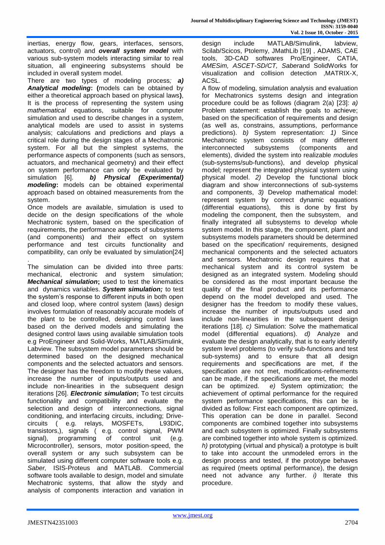
IV.V TOPOLOGICAL AND PHYSICAL MODELING
In [59] is described the implementation of the VDI 2206 design guideline during the modeling of a mechanism for a medical device which is operated with an electric linear actuator. The topological, physical, mathematical and numerical models are obtained and proposed in order to improve an existing design. Three topological models (topological model, describes and reflects interlinks, the function-performing elements, basically the relative position between each component, without considering the physics behind) were suggested as shown in Figure 8, The main difference among them was the node
Journal of Multidisciplinary Engineering Science and Technology (JMEST)
ISSN: 3159-0040
Vol. 2 Issue 10, October - 2015
www.jmest.org
JMESTN42351003 2713
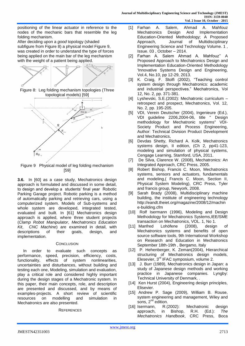
positioning of the linear actuator in reference to the nodes of the mechanic bars that resemble the leg folding mechanism. After deciding upon a good topology (shaded subfigure from Figure 8) a physical model Figure 9, was created in order to understand the type of forces being applied on the main bar of the leg mechanism with the weight of a patient being applied.
Figure 8: Leg folding mechanism topologies (Three
topological models) [59]
Figure 9 Physical model of leg folding mechanism
[59] 3.6. In [60] as a case study, Mechatronics design approach is formulated and discussed in some detail, to design and develop a students‟ final year Robotic Parking Garage project. Robotic parking is a method of automatically parking and retrieving cars, using a computerized system. Models of Sub-systems and whole system are developed, integrated tested, evaluated and built. In [61] Mechatronics design approach is applied, where three student projects (Clamp Robot Manipulator, Mechatronics Education Kit, CNC Machine) are examined in detail, with descriptions of their goals, design, and implementation.
CONCLUSION
In order to evaluate such concepts as performance, speed, precision, efficiency, costs, functionality, effects of system nonlinearities, uncertainties and disturbances, without building and testing each one, Modeling, simulation and evaluation, play a critical role and considered highly important during the design stages of a Mechatronic system. In this paper, their main concepts, role, and description are presented and discussed, and by means of examples-projects. A short review of scientific resources on modelling and simulation in Mechatronics are also presented.
REFERENCES
[1] Farhan A. Salem, Ahmad A. Mahfouz Mechatronics Design And Implementation Education-Oriented Methodology; A Proposed Approach, Journal of Multidisciplinary Engineering Science and Technology Volume. 1 , Issue. 03 , October – 2014.
[2] Farhan A. Salem Ahmad A. Mahfouz‟‟ A Proposed Approach to Mechatronics Design and Implementation Education-Oriented Methodology 'Innovative Systems Design and Engineering, Vol.4, No.10, pp 12-29, 2013.
[3] K. Craig, F. Stolfi (2002), “Teaching control system design through Mechatronics: academic and industrial perspectives.” Mechatronics, Vol 12, No. 2, pp. 371-381.
[4] Lyshevski, S.E.(2002): Mechatronic curriculum – retrospect and prospect, Mechatronics, Vol. 12, No. 2, pp. 195-205.
[5] VDI, Verein Deutscher (2004), Ingenieure (Ed.), VDI guideline 2206,2004-06, title '' Design methodology for Mechatronic systems'' VDI-Society Product and Process Engineering, Author: Technical Division Product Development and Mechatronics,
[6] Devdas Shetty, Richard A. Kolk, Mechatronics systems design, II edition, (Ch 2, pp41-123, modeling and simulation of physical systems, Cengage Learning, Stamford, USA, 2011.
[7] De Silva, Clarence W. (2008), Mechatronics: An Integrated Approach, CRC Press, 2005.
[8] Robert Bishop, Francis C. Moon, Mechatronics systems, sensors and actuators, fundamentals and modeling,( Francis C. Moon, Section II, Physical System Modeling), CRC Press, Tyler and francis group, Newyork, 2008.
[9] Sarah Brady (2008), Multidisciplinary machine building, the institute of engineering technology http://eandt.theiet.org/magazine/2008/12/machine-building.cfm
[10] Rolf Isermann (1996), Modeling and Design Methodology for Mechatronics Systems,IEE/SME transaction on Mechatronics, VOL. 1, No 1.
[11] Manfred Lohöfene (2008), design of Mechatronics systems and benefits of open source software tools, 9th International Workshop on Research and Education in Mechatronics September 18th-19th , Bergamo, Italy
[12] P. Hehenberger, K. Zeman(2004), Hierarchical structuring of Mechatronics design models, Elesevier, 3
rd IFAC symposium, volume 2.
[13] J. Burr (1989), Mechatronics design in Japan: a study of Japanese design methods and working practice in Japanese companies. Lyngby: Technical University of Denmark, .
[14] Ken Hurst (2004), Engineering design principles, Elisevier.
[15] Andrew P. Sage (2009), William B. Rouse, system engineering and management, Wiley and sons, 2
nd edition.
[16] Isermann, R.(2002): Mechatronic design approach, in Bishop, R.H. (Ed.): The Mechatronics Handbook, CRC Press, Boca

Journal of Multidisciplinary Engineering Science and Technology (JMEST)
ISSN: 3159-0040
Vol. 2 Issue 10, October - 2015
www.jmest.org
JMESTN42351003 2714
Raton, Section I: Overview of Mechatronics, chapter. 2, page. 3.
[17] L Al-Sharif (2010), A Saleem, and TA Tutunji, Mechatronic system design: The ideal capstone course? 7th International Symposium on Mechatronics and its Applications (ISMA), , also L Al-Sharif "Mechatronics System Design 0908531: Course Notes", Mechatronics Engineering Department, University of Jordan.
[18] A. Saleema (2011), T. Tutunji and L. Al-Sharif, Mechatronic system design course for undergraduate programmes,European Journal of Engineering Education,Vol. 36, No. 4, August 2011, 341–356.
[19] Manfred Lohöfener (2008), design of Mechatronics system and benefits of open source software tools, 9th International Workshop on Research and Education in Mechatronics September 18th-19th , Bergamo, Italy.
[20] John Billingsley (2008), ''Essentials of Mechatronics'' , John Wiley & Sons,2006. Kenway Chen, Jitesh Panchal, Dirk Schaefer , an integrated approach to design Mechatronics systems: cross-disciplinary constraint modeling'' , ASME International Design Engineering Technical Conferences & Computers and Information in Engineering Conference, IDETC/CIE 2008, New York City .
[21] De Silva, Clarence W. (2008), Mechatronics: An Integrated Approach, CRC Press, 2005.
[22] Sarah Brady (2008), Multidisciplinary machine building, the institute of engineering technology http://eandt.theiet.org/magazine/2008/12/machine-building.cfm.
[23] Vasilije S. Vasić (2008), Mihailo P. Lazarević, Standard Industrial Guideline for Mechatronic Product Design , FME Transactions, 104 , vol. 36, No 3.
[24] Devdas Shetty, Lou Manzione, Ahad Ali, Survey of Mechatronic Techniques in Modern Machine Design , Journal of Robotics , Volume 2012, Article ID 932305, 9 pages.
[25] Ortiz Sánchez-Navarro D., Méndez-Canseco M. and Vargas-Soto E. „‟Mechatronics Methodology Applied toDesign and Control of a Mobile Robot‟‟ 2007.
[26] F. Bruno, F. Caruso, L. Falbo, M. Muzzupappa, a co-simulation based design methodology for Mechatronics peoducts , international conference on engineering design ICED's 07,28-31 august, 2007, France.
[27] Farhan A. Salem, Mechatronics Design of a Mobile Robot System, I.J. Intelligent and application, IJISA, 2013,03,23-36.
[28] Farhan A. Salem, Mechatronics Design of Ball and Beam System: Education and Research, Control Theory and Informatics , Vol.3, No.4, 2013.
[29] Farhan A. Salem, Mechatronics Design of Solar Tracking System, International Journal of Current Engineering and Technology, Vol.3, No.3, 2013.
[30] Farhan A. Salem, Mechatronics Design of Small Electric Vehicles; Research and Education, International Journal of Mechanical & Mechatronics Engineering IJMME-IJENS Vol:13 No:01,pp23-36,2013.
[31] Farhan A. Salem, Mechatronics Design of Motion Systems; Modeling, Control and Verification. International Journal of Mechanical & Mechatronics Engineering IJMME-IJENS Vol:13 No:02 pp1-17,2013.
[32] Farhan A. Salem, Refined models and control solutions for Mechatronics design of mobile robotic platforms , Estonian Journal of Engineering, 2013, 19, 3, 212–238.
[33] Farhan A. Salem,Mechatronics motion control design of electric machines for desired deadbeat response specifications, supported by new MATLAB built-in function and simulink model, European Scientific Journal December 2013 edition vol.9, No.36.
[34] Farhan A. Salem , Ahmad A. Mahfouz, Dynamic Modeling, Simulation and Control of Electric Machines for Mechatronics Applications, international journal of control, automation and systems Vol.1, No, April 2013.
[35] Farhan A. Salem , Performance Analysis, Controller Selection And Verification Of Electric Motor For Mechatronics Motion Control Applications, Using New MATLAB Built-In Function And Simulink Model, I.J. Engineering and Manufacturing, 2013, 2, 11-39.
[36] Ahmad A. Mahfouz , Mohammed M. K. , Farhan A. Salem , Modeling, Simulation and Dynamics Analysis Issues of Electric Motor, for Mechatronics Applications, Using Different Approaches and Verification by MATLAB/Simulink, I.J. Intelligent Systems and Applications, 2013, 05, 39-57.
[37] Farhan A. Salem , modeling and control solutions for electric vehicle, , European Scientific Journal May 2013 edition vol.9, No.15.
[38] Farhan A. Salem, New refined Model for Mechatronics design of solar mobile robotic platforms, International Journal of Scientific & Engineering Research, Volume 5, Issue 8,August-2014.
[39] Farhan A. Salem, Modeling and Simulation issues on PhotoVoltaic systems, for Mechatronics design of solar electric applications, IPASJ International Journal of Mechanical Engineering (IIJME), Volume 2, Issue 8, August 2014.
[40] Farhan A. Salem, New Generalized Photovoltaic Panel-Converter system model for Mechatronics design of solar electric applications, International Journal of Scientific & Engineering Research, Volume 5, Issue 8,August-2014.
[41] Farhan A. Salem, Dynamic and Kinematic models and control for differential drive mobile robots, International Journal of Current

Journal of Multidisciplinary Engineering Science and Technology (JMEST)
ISSN: 3159-0040
Vol. 2 Issue 10, October - 2015
www.jmest.org
JMESTN42351003 2715
Engineering and Technology, Vol.3, No.2 (June 2013)
[42] Farhan A. Salem, New refined Model for
Mechatronics design of solar differential drive mobile robotic platforms, International Journal Of Engineering And Computer Science , Volume 3 Issue 9, September 2014 Page No. 8399-8417.
[43] Mohammed M. K. Farhan A. Salem, Modeling, Simulation and Control Solutions For Mechatronics Design of Solar Light Tower, IJISET - International Journal of Innovative Science, Engineering & Technology, Vol. 1 Issue 7, September 2014.
[44] Farhan A. Salem, Ali S. Alosaimy, Modeling and Control Solutions for Mechatronics Design of Solar Battery Electric Vehicles, International Journal Of Engineering And Computer Science, Volume 3 Issue 9, September 2014 Page No. 8418-8438.
[45] Farhan A. Salem, Mechatronics Design of Solar Tracking System, International Journal of Current Engineering and Technology, Vol.3, No.3, 2013.
[46] Farhan A. Salem, Refined models and control solutions for Mechatronics design of mobile robotic platforms , Estonian Journal of Engineering, 2013, 19, 3, 212–238.
[47] Mohammed M. K. Farhan A. Salem, Modeling, Simulation and Control Solutions For Mechatronics Design of Solar Light Tower, IJISET - International Journal of Innovative Science, Engineering & Technology, Vol. 1 Issue 7, September 2014.
[48] Farhan A. Salem, Mechatronics Design of Motion Systems; Modeling, Control and Verification, International Journal of Mechanical & Mechatronics Engineering IJMME-IJENS Vol:13 No:02,2013.
[49] Farhan A. Salem, modeling and control solutions for electric vehicle, European Scientific Journal May 2013 edition vol.9, No.15, 2013.
[50] Farhan A. Salem, Mechatronics Design of Ball and Beam System; Education and Research, International Journal of Computational Engineering Research, Vol, 03, Issue, 9, 2013.
[51] Farhan A. Salem, Dynamic Modeling, Simulation and Control of Electric Machines for Mechatronics Applications, INTERNATIONAL JOURNAL OF CONTROL, AUTOMATION AND SYSTEMS VOL.1 NO.2 APRIL, 2013.
[52] Rajarishi Sinha, Vei-Chung Liang, Christiaan J.J. Paredis, Pradeep K. Khosla, Modeling and simulation methods for design of engineering system,
[53] Farhan A. Salem, A Proposed Approach To Mechatronics Design And Implementation Education-Oriented Methodology,Case Study; Mechatronics Design Of Smart Guidance System-Smart Mechatronics Wheelchair, Journal of Multidisciplinary Engineering Science and Technology Volume. 1 , Issue. 03 , October – 2014.
[54] Ayman A. Aly, Hardware-in-the-loop of Simulation for a Hydraulic Antilock Brake System, I.J. Intelligent Systems and Applications, 2013, 02, 91-95.
[55] Hans-Petter Halvorsen, Telemark University College, Norway. , http://home.hit.no/~hansha/
[56] Daniel Simon. Hardware-in-the-loop test-bed of an Unmanned Aerial Vehicle using Orccad. 6th National Conference on Control Architectures of Robots, May 2011, Grenoble, France. 14p.<inria-00599685>,https://hal.inria.fr/inria-00599685/PDF/Simon-hardware.PDF
[57] Kresimir, Cosic, Ivica Kopriva, Todor Kostic, Miroslav Slamic,Marijo Volarevi, Design and implementation of a hardware-in-the- loop simulator for a semi-automatic guided missile system, Simulation Practice and Theory7 (1999)107-123.
[58] M. Bacic, On hardware-in-the-loop simulation, Proceedings of the44th IEEE Conference on Decision and Control, and the European Control Conference 2005 Seville, Spain, December 12-15, 2005.
[59] Alejandro Velásquez López1, Mauricio Aramburo Londoño, Olga L. Barrientos Isaza , Modelling of mechanisms according to VDI 2206, Virtual Concept International Workshop, Medellin – Colombia, March 2014.
[60] A. Saleem, T. Tutunji L. Al-Sharif, Mechatronic system design course for undergraduate Programmes, European Journal of Engineering Education Vol. 36, No. 4, August 2011, 341–356.
[61] Tarek A. Tutunji, Ashraf Saleem, and Saber Abd Rabbo, An Undergraduate Mechatronics Project Class at Philadelphia University, Jordan: Methodology and Experience, IEEE Transaction on Education, Vol. 52, N0. 3, August,2009.