Embed Size (px)
Citation preview

S^>*-tL
OFS 1999-5
THE ROLE OF HYDRAULIC, CHEMICAL, AND BIOLOGICAL FACTORSIN THE DECLINE OF SPECIFIC CAPACITY IN THE WESTERNCHAMPAIGN WELL FIELD: A PRELIMINARY INVESTIGATION
Edward Mehnert, Keith C. Hackley, David R. Larson, and Samuel V. Panno
557
IL6of
1999-5
200
.....: ..
Specific Capacity vs Time
01/01/64 01/01/72 01/01/80 01/01/88 01/01/9601/01/68 01/01/76 01/01/84 01/01/92
Final Report to
Northern Illinois Water Corporation, Champaign, IL
Open File Series 1999-5
ILLINOIS STATE GEOLOGICAL SURVEYWilliam W. Shilts, Chief
Natural Resources Building
615 East Peabody Drive
Champaign, IL 61820-6964
APR 1 1999

LIBRARY.

CONTENTS
ABSTRACT 1
BACKGROUND 1
OBJECTIVE 6
SUMMARY OF TASKS COMPLETED 6
Task 1 : Review of Available Information 6
Task 2: Assess Accuracy of Specific Capacity Measurements 6
Task 3: Assess the Effect of Pumping Schedules and Aquifer Geometry 7
Task 4: Analyze Grouhdwater Geochemistry from NIWC Wells 21
SUMMARY 44
RECOMMENDATIONS 45
REFERENCES 46
ACKNOWLEDGMENTS 48
APR 1 1999
9L (tout. *vft«h«

Digitized by the Internet Archive
in 2012 with funding from
University of Illinois Urbana-Champaign
http://archive.org/details/roleofhydraulicc19995mehn

ABSTRACT
Northern Illinois Water Corporation (NIWC) requested technical assistance from the
Illinois State Geological Survey (ISGS) to help determine the cause or causes of the observed
decline in specific capacity of wells in its western well field. Specific capacity is a measure of a
well's productivity and equals the pumping rate divided by the drawdown in the pumping well.
Through a review of available records and data gathered from limited field and laboratory
investigations, we identified hydraulic and geochemical factors as the probable causes for the
observed decline in specific capacity, but biological factors do not appear to have a significant role.
Hydraulic factors include well interference and entrance velocities exceeding the threshold level of
6 ft/min. The chemical data suggest that carbonate and iron minerals could be precipitating and
reducing the porosity and hydraulic conductivity within a 100-foot radius of each affected well.
Precipitation of these minerals could be associated with reduced hydrostatic pressure due to
drawdown and concomitant degassing of carbon dioxide, which could be exacerbated by the
presence of significant amounts of methane.
With the available data, it was not possible to determine whether hydraulic or geochemical
factors were the dominant cause in the observed decline in specific capacity. Additional
investigations are recommended to provide the data to resolve this problem.
BACKGROUND
Northern Illinois Water Corporation (NIWC) contracted with the Illinois State Geological
Survey (ISGS) for technical assistance to help determine the cause or causes of the observed
decline in specific capacity of wells in its western well field. The western well field is comprised
of 12 high capacity wells with individual pumping capacities ranging from 1.55 to 3.44 million
gallons per day (MGD) and is located in and around the northwest part of the City of Champaign
(Figure 1). NIWC supplies drinking water to the Cities of Champaign and Urbana, and to
surrounding communities.


Figure 1. Map of study area showing NIWC, USI, HUMKO and Kraft wells

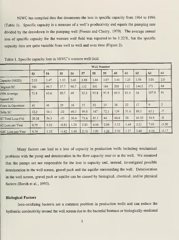
NIWC has compiled data that documents the loss in specific capacity from 1964 to 1996
(Table 1). Specific capacity is a measure of a well's productivity and equals the pumping rate
divided by the drawdown in the pumping well (Freeze and Cherry, 1979). The average annual
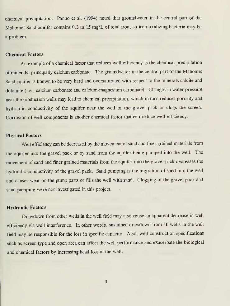
loss of specific capacity for the western well field was reported to be 1.22%, but the specific
capacity data are quite variable from well to well and over time (Figure 2).
Table 1 . Specific capacity loss in NIWC i; western well field
Well Number
53 54 55 56 57 58 59 60 61 62 63 64
Capacity (MGD) 2.55 3.47 1.55 2.43 2.68 3.44 3.07 3.41 3.25 3.54 3.01 2.0
Original SC 106 99.7 57.7 98.7 132 241 164 208 113 144.5 171 84
1996 Average
\nnual SC
73.8 45.6 89.7 49 32.2 93.8 91.9 69.5 81.4 56 107.9 91
Years in Operation 41 41 39 36 35 33 35 26 22 17 9 2
Delta SC 32.2 54.1 -32 49.7 99.8 147 72.1 139 31.6 88.5 63.1 -7
SC Total Loss (%) 30.38 54.3 -55 50.4 75.6 61.1 44 66.6 28 61.25 36.9 -8
SC Loss per Year 0.79 1.32 -0.82 1.38 2.85 4.46 2.06 5.33 1.44 5.21 7.01 -3.50
}/oSC Loss per Year 0.74 1.32 -1.42 1.40 2.16 1.85 1.26 2.56 1.27 3.60 4.10 -4.17
Many factors can lead to a loss of capacity in production wells including mechanical
problems with the pump and deterioration in the flow capacity near or at the well. We assumed
that the pumps are not responsible for the loss in capacity and, instead, investigated possible
deterioration in the well screen, gravel pack and the aquifer surrounding the well. Deterioration
in the well screen, gravel pack or aquifer can be caused by biological, chemical, and/or physical
factors (Borch et al., 1993).
Biological Factors
Iron-oxidizing bacteria are a common problem in production wells and can reduce the
hydraulic conductivity around the well screen due to the bacterial biomass or biologically-mediated


250
Time vs. Specific Capacity*(*= Specific Capacity calculated annually, Jan. 1st to Dec 3 1st)
01/01/64 01/01/72 01/01/80 01/01/88 01/01/96
01/01/68 01/01/76 01/01/84 01/01/92
-m— 54 55 —^— 59 63
Figure 2. Specific capacity of selected NIWC wells

chemical precipitation. Panno et al. (1994) noted that groundwater in the central part of the
Mahomet Sand aquifer contains 0.3 to 15 mg/L of total iron, so iron-oxidizing bacteria may be
a problem.
Chemical Factors
An example of a chemical factor that reduces well efficiency is the chemical precipitation
of minerals, principally calcium carbonate. The groundwater in the central part of the Mahomet
Sand aquifer is known to be very hard and oversaturated with respect to the minerals calcite and
dolomite (i.e., calcium carbonate and calcium-magnesium carbonate). Changes in water pressure
near the production wells may lead to chemical precipitation, which in turn reduces porosity and
hydraulic conductivity of the aquifer near the well or the gravel pack or clogs the screen.
Corrosion of well components is another chemical factor that can reduce well efficiency.
Physical Factors
Well efficiency can be decreased by the movement of sand and finer grained materials from
the aquifer into the gravel pack or by sand from the aquifer being pumped into the well. The
movement of sand and finer grained materials from the aquifer into the gravel pack decreases the
hydraulic conductivity of the gravel pack. Sand pumping is the migration of sand into the well
and causes wear on the pump parts or fills the well with sand. Clogging of the gravel pack and
sand pumping were not investigated in this project.
Hydraulic Factors
Drawdown from other wells in the well field may also cause an apparent decrease in well
efficiency via well interference. In other words, sustained drawdown from all wells in the well
field may be responsible for the loss in specific capacity. Also, well construction specifications
such as screen type and open area can affect the well performance and exacerbate the biological
and chemical factors by increasing head loss at the well.


OBJECTIVE
The purpose of this project was to determine, in a preliminary fashion, the significance of
hydraulic, chemical, and biological factors that may contribute to the observed decline of specific
capacity in NIWC's western well field. Theoretically, this decline may be explained by a
combination of these factors or by a single factor.
SUMMARY OF TASKS COMPLETED
Five tasks were planned and completed for this project. A summary of the work completed
and results follows.
Task 1: Review of Available Information
Records were copied from NIWC's files by project staff on August 25th through 27th,
1998. Most records in NIWC's files were organized by well. These records were reviewed.
Pertinent data were entered into spreadsheets to facilitate analysis. Additional records were
obtained from Mark Johnson of NIWC at later dates.
Task 2: Assess Accuracy of Specific Capacity Measurements
Because NIWC 55, NIWC 57, and NIWC 58 were not pumped for 2 to 3 week period,
these wells were selected as the wells to be used to assess the accuracy of the specific capacity
measurements by comparing water levels measured with an air line and a 200-foot Keck® water
level sensor. Of these wells, only NIWC 55 was thought to have an access port that would allow
measurement of the water level with the water level sensor.
On October 5, 1998, an attempt was made to measure the static water level in NIWC 55
prior to pumping for sampling. The static water level in the well was measured using a hand
operated, bicycle pump hooked up to the air line. The gauge reading was between 20 and 22 psi,
which corresponds to water depths between 133.80 feet and 129. 18 feet. The length of the air line
as of June 18, 1992 is 180 feet.


A threaded plug near the base of the well head on the north side was opened and the sensor
lowered its entire length of 200 feet without detecting water. This opening in the wellhead is
apparently located over the space between the 14-inch and 24-inch casings. No other openings
were found through which the 8-inch long, metal tip of the water level sensor could be passed and
lowered into the well. It is not known if the other wells in the western well field have access ports
to allow measurement of water levels independent of the air line. This task proved not to be
feasible because the water level could not be determined using a water level sensor.
Task 3: Assess the Effect of Pumping Schedules and Aquifer Geometry
A decline in specific capacity can be caused by an increase in the head loss in a pumping
well. Head loss in a well is the sum of the head loss within the aquifer and head loss at the well.
In this section, head losses within the aquifer are evaluated first, then head losses at the well.
Head Losses within the Aquifer
Interference from other pumping wells and proximity of aquifer boundaries can be factors
affecting the head loss within an aquifer. To evaluate the head loss in pumping wells, the
geometry and various properties of the aquifer must be known. A literature search and records
review were conducted to define the aquifer geometry in the vicinity of NIWC's western well field
and to determine certain aquifer parameters. Pumping test data obtained from NIWC were also
analyzed to estimate aquifer parameters. These parameters were used to compute steady-state and
transient drawdowns in the western well field.
Review ofAvailable Information
Data on the aquifer geometry were obtained from publications and by mapping an area
slightly larger than the western well field. This aquifer is comprised of sand and gravel that filled
the bedrock valley; thus, the base of the aquifer is defined by the bedrock surface. Using available
well logs from the ISGS log library, NIWC files, and the Illinois State Water Survey (ISWS) log
library, three maps were prepared for the study area: Elevation of the Bedrock Surface (Figure
3), Elevation of the Top of the Mahomet Sand aquifer (Figure 4), and Thickness of the Mahomet

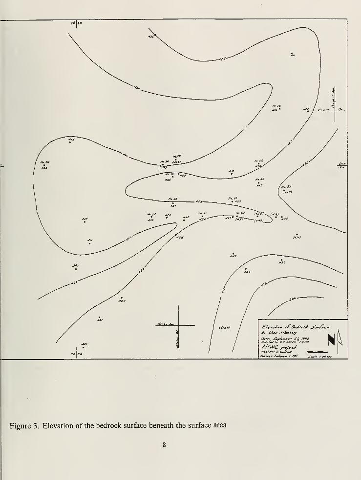
Figure 3 . Elevation of the bedrock surface beneath the surface area


-)L St
Figure 4. Elevation of the top of the Mahomet Sand aquifer beneath the study area


Sand aquifer (Figure 5).
The bedrock has an irregular surface beneath Champaign County (Figures 3 and 6).
Beneath the City of Champaign, the bedrock surface is relatively high and slopes down into the
axis of the NE-SW trending bedrock valley northwest of Champaign. This bedrock valley is the
principal control on the thickness of the Mahomet Sand aquifer (Figure 5).
The Mahomet Sand aquifer is a confined aquifer. To assess the drawdown from wells
completed in a confined aquifer, estimates of aquifer thickness (b), hydraulic conductivity (K) and
storativity (S) are needed. The literature was reviewed to obtain estimates of the hydraulic
characteristics of the aquifer. Values for hydraulic conductivity (K), transmissivity (T), storativity
(S), specific capacity of the aquifer, and leakage for the upper confining layer were obtained from
the literature and include data from Champaign County and 16 other counties in central Illinois
(Table 2).
Analysis of Pumping Test Data
No estimates of K and S were available in the NIWC records, but pumping test data in
those records were analyzed using AQUITEST (Heidari and Moench, 1997) to estimate K and S.
The available pumping test data did not always allow S to be estimated, because data from
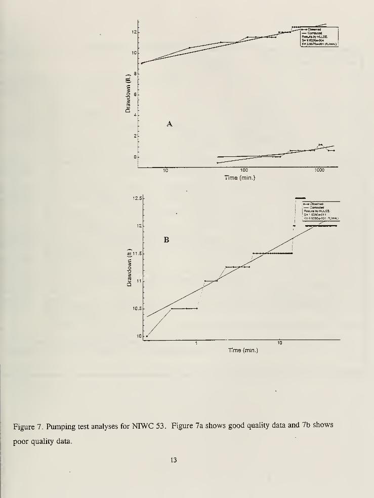
observation wells were not always collected. The quality of the pumping test data were variable,
as seen in Figure 7. Better quality data are shown in Figure 7a, while lower quality data are
shown in Figure 7b. The latter pumping test (Figure 7b) had a very short duration and the
minimum change in head was 0.25 ft. Somewhat surprisingly, the estimates of K (0.37 and 0.70
ft/min) from these two pumping tests are similar.
The following ranges were determined by analyzing 12 pumping tests- hydraulic
conductivity from 0.075 to 3.3 ft/min, and storativity from 2.0xl0"4
to 6.6xl0"2
. Aquifer
thickness was determined from NIWC's well logs. Aquifer thickness at the NIWC wells ranges
from 34 feet at NIWC 57 to 111 feet at NIWC 65 and averages 78 feet (Table 3). In the
10


! !1 LtJ '' »'
IV*///,
Of CA'J Arimmi —J
AJ/IA/C />"j*<t
N k
Figure 5. Thickness of the Mahomet Sand aquifer beneath the study area
11


Figure 6. Map of bedrock surface (from Herzog et al., 1994). The contour interval is 50 feet. The
original map scale was 1:500,000
12

12
10
^ 8
c
3 6
4 -
0-
•—•Observed— ComputedResumby NULSE.S"9S200e-004K" 3.6S70S-OO1 (ft_/mm_)
10 100
Time (min.)
1000
12.5
r •—• Observed
,— Computed
'i
iResults ov NLLSE.
I;S» 1 53809-011
K=5 9590e-001 irijmn.)
12I /
B ^I
C11.5
c5
-
Drawdo
As^lS
10.5 •-^/
10-./
1 10
Time (min.)
Figure 7. Pumping test analyses for NIWC 53. Figure 7a shows good quality data and 7b shows
poor quality data.
13


Table 2. Summary of aquifer characteristics obtained from published sources
T(frVmin)
K (ft/min)
range median
^vertical
(ft/min)
Leakage
coeff.
(min1
)
Source: Cooperative Groundwater Report 8 (Kempton et al., 1982)
Lithology Drift, sand and gravel,
some clay and silt
(Walton, 1965)
Dirty sand and gravel
-Banner Formation*
Aquifer tests Mahomet Sand
Specific-
apacity data
Data from
Appendix 1 for
H9N, R8E
Other aquifers in
the Banner Formation
Mahomet Sand
Other aquifers in
the Banner Formation
USI3
6.57 to 30.2
0.088 to 10.9
0.436 to 65.9
0.028 to 9.10
Wells within the Banner
Formation
Wells withm the
Glasford Formation
19.0
13.0 to 46.4
0.1 7 to 0.444
0.011 to 0.246
0.0148 to 0.720
0.0074 to 0.464
0.189
0.280
0.084
0.281
0.045
0.48 to 6.87
0.189 to 0.716
0.025 to 0.247
0.305
1 e-04 to
2.3e-03
1.3e-04to
1.8e-03
2.3e-03
0.175
.e-04
9e-05 to
1.5e-04
3.9e-05
3.1 e-04 to
2.3e-03
Source: Cooperative Groundwater Report 16 (Wilson et al. [1994])
Aquifer tests Aquifer test
in Basal Aquifer
7 day calculated
values
Sankoty-Mahomet
Aquifer
0.57 to 47.7
31.8
0.057 to 0.382
0.27
0.205 1.e-04 to
9.e-02
5.7e-04 1.2e-04
Source: Report of Investigation 62, (see Table 3 T19N, R8E in Visocky and Schicht, 1969)
Champaign
County wells
Sand and gravel,
some clay
All wells Sand and gravel,
some clay to gravel,
boulders
18.9 to 30.0
5.17 to 30.0
0.19 to 0.31
0.029 to 0.368
0.281
0.173
4.1 e-04 to
2.3e-03
2.17e-05 to
2.3e-03
1 .64e-05 to
3.9e-05
8.4e-07 to
1.13e-03
1.66
107.2
Unadjusted
Cs (fr/min)
0.26 to 27.7
0.027 to 5.35
1.01 to 1.21
0.024 to 56.0
* Results from controlled aquifer tests carried out in wells in T19N, R8E of Champaign County within the Banner
Formation, (from Cooperative Report 8, Table 1, Kempton et al. [1982])
14


Table 3. Aquifer thickness at the NIWC wells
NIWC Well Number Reported Aquifer Thickness (ft)
53 102
54 >79
55 53
56 55.5
57 34
58 66.5
59 >108
60 93
61 89
62 97
63 51
64 97
65 111
drawdown calculations, the following values were used-- 78 ft for b, 0.50 ft/min for K and 0.001
forS.
Estimation ofDrawdown and Well Interference
With the estimated values of b, K, and S, the drawdown in various wells was estimated.
Steady-state and transient drawdown were computed for several wells. Steady-state drawdown is
the drawdown that occurs some time in the distant future and represents the maximum drawdown.
Because continuous and constant pumpage, which was assumed for the steady-state drawdown
calculations, is not realistic, transient or time-dependent drawdown was also calculated. NIWC
does not continuously pump its wells for extended periods (years at a time), so transient drawdown
better represents its operations. The steady-state and transient drawdowns were computed using
analytical solutions from Bear (1979).
15


Well interference is the drawdown imposed on a pumping well from another pumping well
and is common in areas with closely spaced wells. To evaluate well interference, drawdown was
estimated for two clusters of three wells each. The first cluster is comprised of three wells, NIWC
61, NIWC 63, and NIWC 64, and is referred to as the "tight cluster" because the wells are 2,600
to 4,900 feet apart. The second cluster is comprised of three wells, USI 2, NIWC 61, and NIWC
65, and is referred to as the "distant cluster" because the wells are 12,000 to 25,000 feet apart.
The drawdown data were computed with the data in Table 4, assuming all three wells were
pumping at a constant rate. The transmissivity value in Table 4 was calculated using an average
aquifer thickness of 78 feet and hydraulic conductivity of 0.5 ft/min. In addition, the wells were
assumed to fully penetrate the aquifer.
The steady-state drawdown for wells in the tight cluster ranged from 9.6 to 10.6 ft, with
the largest drawdown estimated for NIWC 63. The percentage of the total drawdown due to the
pumpage from the other two wells ranged from 34 to 47% for wells in the tight cluster and 20 to
46% for wells in the distant cluster. These results show that, for steady-state conditions, well
interference is very significant. To understand how long its takes for well interference to become
significant, transient analysis was undertaken.
Table 4. Input data used to compute drawdown
Parameter Units Value
Transmissivity ft2/min 39
Storativity ~ io-3
Pumpage from NIWC 61 gpm 859
Pumpage from NIWC 63 gpm 1034
Pumpage from NIWC 64 gpm 766
Pumpage from NIWC 65 gpm 1378
Pumpage from USI 2 .gpm 1767
16


Well interference at NIWC 61 exceeds 5% of total drawdown after 200 minutes of
pumping for the tight cluster and after 2,000 minutes (33 hours) for the distant cluster (Figure 8).
Well interference at NIWC 61 exceeds 20% of total drawdown for both clusters after 10,000
minutes (6.9 days). The effects of transmissivity and storativity can also be seen on Figure 8.
Lower S and higher T results in significantly greater well interference at NIWC 61 for the distant
cluster.
If well interference is a significant cause, then drilling and start-up of a new well in the
Mahomet Sand aquifer should affect specific capacity (Figure 9). For example, after NIWC 63
(5,300 feet from NIWC 54 and 4,600 feet from NIWC 55) began operating in July 1988, a
significant drop in the specific capacity of NIWC 54 or NIWC 55 would be expected, but it did
not occur. In fact, no significant changes in specific capacity could be associated with the start-up
of NIWC 63 or any other new well.
These calculations showed that well interference is significant for the given input data, after
short periods (hours to days) and over the long run. Well interference or drawdowns imposed by
neighboring wells may be interpreted as reductions in specific capacity and may explain the
observed decreases in specific capacity. NIWC has increased its pumpage from the Mahomet Sand
aquifer by 102% from 1964 to 1996. The production history of high-capacity wells that are not
owned by NIWC is unknown, so the effect of these wells on specific capacity can not be
evaluated. Increased production from the aquifer supports the argument for well interference as
a factor in the overall trend of declining specific capacity. In addition, the minor variations in the
specific capacity data may be accounted for by transient pumpage. However, obvious declines in
specific capacity do not appear to be related to the presence of new wells in the aquifer.
The analytical solutions used to determine drawdown required the use of constant values
of aquifer thickness, hydraulic conductivity, and storativity. For the NIWC wells, the values of
aquifer thickness and hydraulic conductivity are known to vary from 34 to 111 feet and 0.075 to
17


Interference from 2 Other Wells
(% of drawdown due to other wells)
1E1 1E2 1 E3 1 E4time (min)
1E5 1E6
NIWC 61 w/ NIWC 63 & 64 NIWC 61 w/ NIWC 65 & US1 2
I- NIWC 61 w/ NIWC 65 & USI 2 (lower S) —W~ NIWC 61 w/ NIWC 65 & USI 2 (higher T)
Figure 8. Transient drawdown for the tight and distant cluster
18


Date well
in routine Well 58
operation: 08/64
250 -
Time vs. Specific Capacity*(*= Specific Capacity calculated annually, Jan. 1st to Dec 3 1st)
Well 62 Well 63
10/81 07/88
01/01/64 01/01/72 01/01/80 01/01/88 01/01/96
01/01/68 01/01/76 01/01/84 01/01/92
Figure 9. Specific capacity as a function of time and the addition ofnew wells to the well field
19


3.3 ft/min, respectively. While the analytical solutions can provide reasonable estimates of
drawdown, a groundwater flow model is needed to improve these estimates. Unfortunately,
additional geologic and hydrogeologic data are needed before the effort of developing a high
quality, groundwater flow model could be justified. Important hydrogeologic data including
transmissivity, storativity, leakance, anisotropy, and the effect of aquifer boundaries could be
obtained from long-term pumping tests.
Head Losses at the Well
The average entrance velocity of water through the well screen is another factor that affects
the specific capacity of a well. Average entrance velocity is calculated by dividing the pumping
rate by the open area of the well screen and does not account for well inefficiencies such as the
convergence of flow near individual openings of a shutter screen (Driscoll, 1986). Driscoll (1986)
notes that well screens designed to have an average entrance velocity of 0.1 ft/sec (6 ft/min) or
less will reduce well maintenance over time, create minimal head losses as the water enters the
screen, and limit the amount of sand entering the well. Minimizing head losses also reduces the
likelihood that the screen openings will be clogged by chemical precipitation, which can be
induced by changes in pressure as groundwater flows into the well.
For the well capacities given in Table 1, the average entrance velocities were computed
(Table 5). The results do not show a consistent trend between average entrance velocity and
specific capacity. Seven wells have average entrance velocities greater than 6 ft/min and show a
loss in specific capacity. Four wells have average entrance velocities less than 6 ft/min, and also
show a loss in specific capacity. Because the data for some wells show no consistent relationship
between entrance velocity and change in specific capacity, other factors, such as well interference,
may be contributing to the loss of specific capacity. NIWC 61 has the greatest average entrance
velocity, but one of the lower decreases in specific capacity. NIWC 63 has the greatest loss in
specific capacity per year, but has one of the lowest average entrance velocities at 2.63 ft/min,
well below the recommended 6 ft/min. NIWC 55 has an average entrance velocity of 6.23 ft/min,
or slightly greater than the recommended 6 ft/min, but shows a net gain in specific capacity.
20


Table 5. Entrance velocities for NIWC's western well field
NIWC
Well
Well capacity
(gpm)
Total Open
Area (ft2
)
Entrance
velocity
(ft/min)
S.C. loss per
year
Q at 6 ft/min
53 1770.83 38.3 6.18 0.7854 1718.28
54 2409.72 74.2 4.34 1.3195 3329.77
55 1076.39 23.1 6.23 -0.8210 1036.76
56 1687.50 38.3 5.89 1.3806 1718.28
57 1861.11 38.3 6.50 2.8514 1718.28
58 2388.89 53.9 5.93 4.4606 2419.03
59 2131.94 38.3 7.44 2.0600 1718.28
60 2368.06 40.3 7.86 5.3269 1808.60
61 2256.94 32.2 9.36 1.4364 1446.88
62 2458.33 36.8 8.93 5.2059 1652.18
63 2090.28 106.2 2.63 7.0111 4764.51
64 2090.28 80.8 3.46 -3.500 3625.49
65 1770.83 118.6 2.00 ? 5321.02
Task 4: Analyze Groundwater Geochemistry from NIWC Wells
Methods
All water samples were analyzed in the field for temperature, pH, Eh, and specific
conductance. Field measurements for pH and specific conductance were made using meters that
allowed temperature compensation and were calibrated with appropriate standards at each sampling
site. All samples were analyzed for major cations and anions, bacterial species, dissolved organic
carbon, and dissolved gases. Selected samples were analyzed for tritium and atrazine.
Groundwater samples were collected in accordance with field techniques described in
21


Wood (1981). Spigots at the NIWC wells were sterilized with isopropyl alcohol and heated with
a propane torch for about 15 seconds prior to sampling. Water was allowed to flow until pH, Eh,
temperature, and specific conductance readings stabilized, then water samples were collected.
Samples collected for cations, anions, and alkalinity were filtered through 0.45-Mm
membranes and stored in polyethylene bottles. Samples analyzed for cations were acidified in the
field with ultra-pure nitric acid to a pH of 2.0. Samples collected for pesticides were unfiltered
and stored in 60 mL, precleaned amber glass bottles. The samples were transported in ice-filled
coolers to the laboratory, and kept refrigerated at approximately 4 °C until analyses had been
completed. Samples collected for pesticide analysis were filtered in the laboratory prior to
analysis.
Samples collected for bacterial analysis were stored in sterilized 250 mL bottles and
analyzed within 24 hours for total coliform, fecal coliform, and total (other) bacteria using
standard techniques (Clesceri et al., 1989). Determination of bacterial species was conducted at
the Illinois Department of Agriculture's Animal Disease Laboratory, Centralia, IL using standard
methods to isolate and identify bacterial colonies present (Clesceri et al., 1989). All methods used
to separate and identify each species are described in Cason et al. (1991). Field blanks included
sterilized water (deionized water boiled for 30 minutes) that was poured into sample bottles in the
field and poured through sampling spigots in the laboratory. The sampling manifold was soaked
in isopropyl alcohol for at least four hours and dried in an oven at 60 °C overnight prior to
sampling the NIWC wells.
Water samples were analyzed for atrazine using enzyme-linked immunosorbent assays
(ELISA) following manufacturer's instructions. The ELISA technique has been found to yield
data that correlate well with samples analyzed using gas chromatography/mass spectrometry
techniques (Thurman et al., 1990).
Concentrations of cations were analyzed using a Model 1100 Thermo-Jarrell Ash
22


Inductively Coupled Argon Plasma Spectrometer (ICAP). Instrument control, automatic
background correction, and spectral interference corrections were performed using a DEC Micro
PDP 11/23 computer. Solution concentrations of anions were determined using a Dionex 21 li ion
chromatograph, following U.S. EPA Method 300 (O'Dell et al., 1984). All water samples had
charge balance errors of less than 5 %
.
The dissolved gases were sampled from water taken at the well head through a spigot
connected to the main water lines for the NIWC wells and through a Y connection attached to the
pumping hose at the ISWS wells. The sample containers were collapsible, plastic, one gallon
containers which were evacuated with a vacuum pump prior to water sampling. The containers
were brought back to the laboratory, weighed, and the gases extracted that same day using a
syringe. The gases were stored in pre-evacuated glass vials fitted with a septum and analyzed by
a commercial lab for methane (CH4)and carbon dioxide (C02)
by gas chromatography. The
analyses were performed using a gas chromatograph equipped with both a thermal-conductivity
detector and a flame ionization detector. Helium was used as the carrier gas. The component
peak areas were quantified by comparing them to previously run standards. The percentage of
CH4 and C02were converted to concentration of dissolved gas per liter using Henry's Law.
Water samples for tritium analyses were collected in one liter HDPE containers. The
tritium analyses were determined on 200 mL of water using the enrichment technique described
by Ostlund and Dorsey (1977). The tritium enriched samples were purified by vacuum
distillation, mixed with a scintillation cocktail and counted in a low-level scintillation counter
(Packard 2000 CA/LL). The tritium results are reported in tritium units (TU), which is defined
as one tritium atom per 1018 hydrogen atoms.
Groundwater Chemistry
Three NIWC wells (NIWC 55, 57, and 58) were sampled in September 1998 in the middle
of their pumping cycle. The same three wells were sampled in October 1998 following a two to
three week idle period. Each well was sampled sequentially from 30 seconds to 600 seconds after
23


start up. In addition, six wells drilled and maintained by the ISWS that lie along the thalweg of
the Mahomet Sand aquifer (MSA) and between the thalweg and NIWC's western well field were
sampled (Figure 10). A "thalweg" is the line of maximum depth in a stream channel, and is used
herein to refer to that feature in the Mahomet Bedrock Valley.
Groundwater from the Mahomet Sand aquifer in the study area is a relatively dilute, mixed
cation-HC03
" type water (Panno et al., 1994). Relatively low Eh values, low concentrations of
sulfate and nitrate, and the presence of relatively high concentrations of ammonia, iron,
manganese, and methane (Table 6) all are consistent with reducing conditions and isolation from
the atmosphere. Additional data that support the idea that the MSA is isolated from the
atmosphere include the tritium and atrazine concentrations, which were all below detection limits
(Table 6). The chemical composition of groundwater in the study area (Table 6) reflects the
composition of the Mahomet sands, which consists primarily of quartz, feldspar, and carbonate
minerals (calcite and dolomite) (Willman and Frye, 1970).
Analysis of water chemistry data, using the chemical reaction model NETPATH (Plummer
et al., 1994), showed that almost all groundwater samples were saturated to oversaturated with
respect to a variety of carbonate, silica, and iron-bearing minerals (Table 6). These minerals
include calcite, aragonite, dolomite, siderite, quartz, chalcedony, hematite, goethite, and Fe(OH)3
(iron oxyhydroxide). A trend that consistently appeared in the data was that groundwater from the
western well field had a significantly higher degree of saturation with these minerals than did any
groundwater sample from other parts of the MSA. Groundwater from the NIWC's western well
field also had lower partial pressures of C02(pC0
2 ) and lower total dissolved solids (TDS) than
the other samples farther away from the well field (Figure 11). These data suggest that the
groundwater in the western well field is undergoing degassing possibly as a result of lowering of
the hydraulic head in the vicinity of the wells. As stated by Henry's Law, the amount of dissolved
gas in a liquid is proportional to the partial pressure of the gas in contact with the liquid. The
equilibrium expression for the solubility of a gas in water is:
24


,IROQUOIS COI
T22N
T21N
T20N
T19N
T18N
T17N
R5E R6E R7E Contour interval 10 feet
(in feet above mean sea level)
Figure 10. Map showing the location of NIWC and ISWS wells used for groundwater
geochemistry sampling (modified from Wilson et al., 1998). The contours of the potentiometric
surface of the Mahomet Sand aquifer are also shown.
25


enQ
680 -
660 -
640 -
620 -
600 -i
580 -
W-57
560
540
W-58
-2.1 -2
96Ba
94A95B
96A
95D
W-55
H f-
-1.9
H h
-1.8
pC02-1.7
96C
-1.6 -1.5
Figure 11. Comparison of total dissolved solids (TDS) and the partial pressure of C02(pC02)
in
groundwater samples from NIWC and ISWS wells.
26


ooo o i-: so Os p 00 in ^; o
u d — — o O — — — CN d
b00 OO
oSO
moV
as oocsi
M;
mCN
omoV
CNCN
d
ood
E ^dV
QZ
QZ
soSO
dV
QZ
QZ
CN
dV
CNin
dV
az
3 d d do o X X X X X X X X X
in** r~ 00 r> r— CN sO CN CN
X Q Q Q a Q Q r— o * p «-^ p O Os in so CN
z Z Z Z z Z Z O — — d ~ 1'
CN CN *"
'
in ro m" rn
j d d d d d d d d din o X X X X X X X X X
ft so SO SO sO sO so oo oo f^ o _rEX cu £-
* 00 »—
1
»-h CN OS sO CN
b o d o o SO Os 00 fsj *-; ""! r^ OS ^z v" 7 V \7 V V V V d d rr CN CN in ^t CO
Ujbu SO cn ^r t~- SO ^ as * oo O^o
z -EO (N •rf -* CN p in r-
in SO * (N in m oCN CN CN CN r-i CN rn CN
in as 00 »^s r^ in rn CN « o -g-r~ 00
9oo
as 00 sO OS OfN rsi
m ro m Od CN
0000 OS 00
m -
~eo
2modCN
SOCI
o\
mso ro Os
asCN
OSOsCN
COood
"« 0"-s
U fc uu- oo -H- O O
az O
*o 7: 5
uSO
cn
CNOsSO
oo
00
OO
00OO00
PI
SO
OCNin
CN
CNmood O O
Qz O -
Os
Ju CN CN N — rsl V ro V V
CNSO
d«
H U -3 O OQZ O -
Ed
XCN
O en in 1—00m 00
CN SO CNdue
C3
zOs
ob SOmOs
m00
Os
Os
sb<N
rnas
00
CN
d dinCN
d•nCN
d dOp
SOmd d
p.o•— ^^<l>
JH £ "So03 13
e
2 < b"~ u
HC3 O so in CN in m in SO so SO7—1 * OS (N rsi OS rs) O SO in O in r~- in OO CN OQ
o ^H U rn
1^ *m SO in rnc*1 00 sb in ^r sb sb in in sb sb
£o
<§ E s
in CN SO •* >* CN 00 sO CN
00 O SOinSO "3-
Or-
so OsOs
mo 00 £ CO r-j d f> rn CN CN rn rn
usO SO SO so so SO sO SO SO 00
5 >C3
Es* in r-~ Os CN in CN rn CN
O ^r 00 r-~ m sO CN in Os
oors)
r— sO 'I- 00 m "st in r^ sO
a r-o o Csl
Osso as sO
in CO d d d d d d d d ddC3
y^ O<* Os CN _ c^
CNCN r^ Os
-^ O sO m ^r ^r ^r maj X
a.
^r "tf ^r m ro f—t SO sO in CN ^r ^r CN d -* "3; *X r- r> r- r- f~ r~ t-~ t~ t~ 00 d d d d d d d do—Cs5
2 ^ 00 O 00 as oo p fN _ <<
0000O m 00
CNOsin
CNOs
00
-X* rn 't r^l r^> ro ro CO ci
00 d d d d d d d d d
C
•doo JCc _)u
a. oS
ro in 00 m CN
dCN CN
1^rsi rn
00rsi rn
Oo oin
<CN
00CN
00CN
ClCN CN
inCN
SOCN
<d O © O O O o SO 00 d d d d d d d d ds-ooo
175 co
OJ
- ?J -0
oCN
OscnCN rsl
o in mtN
CNCN
asCNCN CN sO
inmSO
SO
sO sO sososO
CNOsin
00in
inin
ac3-^C3 c
1 E b'U 09 x
u ^O ** "J ^sS
OO r— ,_ Os ^4 * as en ^rO ^r r~ m Os in CN SO'5
c ^ & r^ inin
r~4
SO
un
^f
as
Os 00^f SO
CN asOO 00 00 r> r-; in as p
CNOCN
,—
,
OO OO as OO oo ON as as • 1 1 1 1 1
o• "^
dcCs3
00 O0 00 oo 00 O0 U Uc2
in
pen
CNm m in CNO CNO
OsOOO 00 O0 oo oo 00 oo Z z z d d d d d d d d d d
75w
c
E4>
oo oo 00 00 oo ooas OS gs gs OS OS 00 oo 00
d -X Os Os as Oss: 4) P sO
CN CNr- sO sO o d d ro Os r- 00 * r*i — — •—
C^t 00 00 sO 00 r-~ Os rn
i Q ooO o O o o o
Os as Os LL, d d d -I d — — d4.
c)
<.) * < PO Q <SO
CDsO
UsO
co
Ecd
< min
Qin
<SO SO
USO
c
a,
u! &i
i5 oo
Os
2OS Os OS
2Os
2as
2 OOas
00Os
OOas
Os
iOs
2Os Os
2Os
2Os
00Os
00as
00Os
irt
x I X X X X X inin
r-in
00 2 £ X I X X X I m C~~ 00 Sia U u u u u u m a s 00 U u u m m in
E--
X9
c
Hdox>Hcdoo'SCsJ
bO)->
o


[G(aq)]
= KH x P(g)
Where [G(a }
] is the concentration of dissolved gas, KH is Henry's constant for a specific gas at
a certain temperature and P(g)
is the partial pressure of the specific gas. Thus, a liquid can hold
more dissolved gas at higher pressure. As the pressure decreases, the dissolved gas escapes from
the liquid in order to restore equilibrium with the changing system. This relationship is shown in
Figure 12 for water in equilibrium with C02and CH4
at concentrations similar to those observed in
the NIWC wells.
The major dissolved constituents in a confined aquifer, such as the Mahomet Sand aquifer,
are typically considered to be in chemical equilibrium with the minerals that make up
the aquifer material. Changes exerted on the system, such as large scale pumping, upset this
equilibrium. Thus, a drop in pressure due to large scale pumping may decrease the amount of
dissolved C02
in the water through degassing, which in turn will affect the equilibrium of the
carbonate geochemistry of the groundwater, typically resulting in the precipitation of carbonate
minerals within the aquifer, the gravel pack, or the well screen (e.g., Driscoll, 1986). The
relationship between dissolved C02and calcite (CaC0
3 )precipitation is shown more clearly in the
following chemical reaction:
CaC03+ H
2+ C0
2* Ca2+ + 2HCCV
IfC02is released from water, the chemical reaction will be driven to the left, decreasing dissolved
solids (Ca2+
and 2HC03") and precipitating CaC0
3.
Field parameters, TDS and the log pC02are good indicators of changes in groundwater
chemistry resulting from the rate at which a well is pumped. Values ofpH in the ISWS wells (mean
= 7.3 1) are consistently lower than those within the western well field (mean = 7.57). "Mean" in this
case is arithmetic mean calculated by first converting pH values to hydrogen ion concentrations. The
difference in pH is reflected in chemical changes in groundwater that are proportional to the rate of
pumping. Specifically, the log pC02(Figure 13) and TDS (Figure 14) show a linear decrease with
28


1.5 2 2.5 3
Pressure (atmospheres)
C02 CH4
Figure 12. Changes in dissolved carbon dioxide and methane concentrations resulting from changes
in pressure at 25 °C, based on Henry's Law.
29


20 40 60 80 100
Pumping Rate (L/s)
120
Figure 13. The loss ofpC02with increased pumping rate yields a mechanism for the precipitation
of carbonate minerals within the aquifer near NTWC's wells.
30


680
H 580
20 40 60 80 100
Pumping Rate (L/s)
120 140
Figure 14. A linear relationship between pumping rate and total dissolved solids (TDS) is believed
to reflect the loss ofTDS due to precipitation of carbonate minerals within the aquifer surrounding
NTWC's wells.
31


the pumping rate. That is, as the pumping rate from wells in the Mahomet Sand aquifer increases,
the TDS and pC02decrease. The loss ofTDS relative to pumping rate may be calculated from the
least squares equation:
Y = -0.59X + 638
where Y = TDS and X = pumping rate in liters/second (r2 = 0.88 for the mean TDS of the ISWS
wells and three NIWC wells). The average loss in TDS in the NIWC western wells, relative to wells
to the north and west, is about 63 mg/L. This change in TDS represents a significant mass of
dissolved solids that could be precipitating near the NIWC wells, especially when one considers the
volume of water pumped by each well in the western well field. The precipitation of these minerals
could eventually reduce the porosity and hydraulic conductivity of the aquifer around the well and
could be responsible for the loss of specific capacity. The following example demonstrates the effect
precipitation can have on a well:
Assume that calcite precipitates in the pore spaces of the Mahomet Sand aquifer within a
100-foot radius of a production well, and that the aquifer is 50 feet thick. Also assume that
Q
a well is pumped at 1500 gpm for one year, so the total volume of water pumped is 7.9x10
gallons. The amount of calcite (density = 2.71 g/cm3
) precipitating from this water is
1.93xl08g or 7.1xl0
7 cm3. Assuming a porosity between 25 and 50% for a sand and gravel
aquifer (Freeze and Cherry, 1979), and using mean porosity of 38% (a very conservative
estimate given the probable compaction within this aquifer), the total void space in the
cylindrical aquifer segment is 1.7xl010 cm3
. Thus, 0.42% of the void spaces per year or
4.2%o in 10 years would be filled by calcite. The percent loss of porosity depends on the
actual size of the zone of cementation; as the volume of the area of precipitation decreases,
the percent loss of porosity increases asymptotically (Figure 15).
This scenario is consistent with the results of 1995 acidification ofNIWC 57. Acidification
of the well resulted in a significant increase of specific capacity that steadily declined to its previous
level over the course of about one year. If the remediation was effective only in close proximity
to the well and along preferred pathways from the well, then the groundwater flow along these
flowpaths would improve specific capacity. However, the specific capacity would only be
maintained until the porosity of the newly cleared, although smaller flowpaths, was reduced to
32


° TO W 91 '88' W B '79!
95!
73' 'id W W W 'sWVs' 5 W ^ W W '37 W '# 28' '£!
2* W 'l* 'tf 10 7
Distance from well in feet
Figure 15. The percent of void spaces in Mahomet Sand aquifer that could be filled after one year
of pumping a well at a rate of 1500 gallons per minute relative to distance from the well where
precipitation begins. For example, about 41% of the voids are filled if precipitation begins at 10
feet from the well.
33


previous levels. Loss of specific capacity, in this case, would take less time than if groundwater
were allowed to flow through a larger volume of aquifer.
An increase in chloride and decrease in silica in the proximity of the western well field
(Figures 16 and 17) was also observed. The increase in chloride suggests that pumping within the
well field is drawing groundwater with higher concentrations of chloride from a source other than
the MSA. It cannot be determined from available data whether the source of this groundwater is
from older adjacent bedrock or younger beds overlying the Mahomet Sand aquifer. Panno et al.
(1994) showed that groundwater in the underlying bedrock is a Na+-Cl" type groundwater and
would be a likely candidate. Concentrations of Si02in groundwater from the bedrock range from
6.0 to 12.4 mg/L (based on limited data), whereas the groundwater from the MSA and overlying
Glasford sands range from 16.3 to 24.6 mg/L (Panno et al, 1994). Assuming that silicate minerals
are not precipitating within the aquifer, the lower Si02concentrations at and near the NIWC wells
(Figure 17) are consistent with the influx of groundwater from the bedrock.
Bacteria
The bacterial composition of the water from ISWS wells provided background information
about the type of bacteria that might be present in the aquifer. Bacillus subtilis, Pseudomonas
spp., and to a lesser extent Staphylococcus saprophyticus were consistently observed in water
samples from the ISWS wells (Table 7). These genera and species are typical soil bacteria and
could have been introduced into the well or materials around the well during drilling.
Alternatively, because the concentrations are so low and of the same magnitude, they could be
incidental bacteria present (e.g., as a biofilm) in the 60 meters of plastic tubing of our pump. No
Fe- or S-oxidizing bacteria were found in the isolates. The aerobic bacteria in the ISWS wells
were found at levels that ranged from 8 to 207 colony forming units/ 100 mL (cfu). Low bacterial
counts, 10 cfu or less, could be due to airborne bacteria incorporated during sampling (E.C.
Storment, Department of Agriculture, personal communications, 1998). For example, one of four
sterilized field blanks contained 2 cfu of Bacillus subtilis.
34


2.5
]1.5
2keur*c—
^
<u
-oPo
1U
0.5 -
5 10
Distance from West Well Field (mi)
15 20
Figure 16. Chloride increases with proximity to the western well field supporting the hypothesis
that pumpage is attracting groundwater from an adjacent source (in this case, with a higher
chloride concentration).
35


25
20 -
15 -
o10 -
5 -I
10 15 20
Distance from West Well Field (mi)
Figure 17. Silica decreases with proximity to the western well field suggesting the possible influx
of groundwater from a bedrock source.
36


Table 7. Bacterial genera and species isolated from groundwater samples from ISWS and NIWCwells in the Mahomet sands. NIWC samples were collected during normal pumping operations
(cfu = colony forming units/ 100 mL water).
Well No. Total Aerobic Bacteria (cfu) Bacterial Isolates
ISWS 94A 10 Bacillus subtilis
Pseudomonas spp.
ISWS 95B 207 Bacillus subtilis
Pseudomonas spp.
ISWS 95D 108 Bacillus subtilis
Pseudomonas spp.
Staphylococcus saprophyticus
ISWS 96A 88 Bacillus subtilis
Pseudomonas spp.
ISWS 96B 10 Bacillus subtilis
Pseudomonas spp.
ISWS 96C 90 Bacillus subtilis
Pseudomonas spp.
Staphylococcus saprophyticus
NIWC 55 8 Enterobacter agglomerans
Pseudomonas spp.
Staphylococcus xylosus
NIWC 57 10 Enterobacter agglomerans
Pseudomonas spp.
Staphylococcus xylosus
NIWC 58 130 Micrococcus spp.
Bacillus spp.
Bacterial analysis of groundwater collected from NIWC wells during operation revealed
the presence of genera and species slightly different from those of the ISWS wells (Table 7).
Isolates from these samples showed the presence of Enterobacter agglomerans, Pseudomonas spp.
,
Staphylococcus xylosus in NIWC 55 and NIWC 57, and Micrococcus spp. and Bacillus spp. in
NIWC 58. These bacteria were probably not introduced during the sampling of the NIWC wells
because the water samples were collected directly from the well through a cleaned spigot (rinsed
37


with alcohol and flamed). For these wells, the sampling pump, suspected of contaminating
samples collected from the ISWS wells, was not used.
Species of Enterobacteriaceae are often dominant in pipe sediment biofilms and is one of
two strains of coliforms most often involved with noncompliance problems with public water
systems. In addition, Enterobacter, Pseudomonas, and Micrococcus species are known to form
and/or colonize biofilms (Geldreich, 1996). Staphylococcus xylosus, as with all strains of
Staphylococcus, are not known to be naturally-occurring in groundwater systems, but are normal
inhabitants of the human skin (Chapelle, 1992; Geldreich, 1996) and, to a lesser extent, fecal
matter (Antai, 1987) and soils (Alexander, 1977). Their presence may indicate contamination of
the water samples or sample bottles due to handling (Chapelle, 1992) or may indicate the
introduction and colonization of this bacteria genera into the wells or associated distribution
system during construction and maintenance (LeChevallier and Seidler, 1980; Geldreich, 1996).
No Fe- or S-oxidizing bacteria were detected in any of the samples, nor were there any indication
(e.g., staining of filters) of the presence of these bacteria during analysis of the samples.
Surging of the NIWC wells resulted in little change in the groundwater chemistry of the
wells, but did reveal a surprising number of colonies of aerobic bacteria for NIWC 58. The
number of colonies decreased from greater than 600 cm at 30 and 90 seconds to 155 after 300
seconds and to 106 cm after 600 seconds (Table 8). This pattern would be expected if surging
dislodged part of a biofilm. Whether the biofilm is present in the aquifer materials, gravel pack,
or well materials is not known; however, Geldreich (1996) points out that in distribution systems,
biofilms initially form in slow-flow areas. In addition, the highest counts of total aerobic bacteria
from water samples, collected while the three wells were in full operation, were found in NIWC
58. The sample from NIWC 58 had 130 cm, whereas samples from NIWC 55 and NIWC 57 had
only 8 and 10 cm, respectively, during the same period. In general, groundwater samples from
NIWC 55 (a well with little change in specific capacity) and NIWC 58 (a well with a significant
loss in specific capacity) showed little difference in the cm and species. This suggests that any
biofilms present are having little effect on specific capacity.
38


Table 8. Bacterial genera and species isolated from groundwater samples during "surging" of
NIWC wells following a two-week or more "idle period" for the wells.
Well No. Time Since Well
Start UpTotal Aerobic Bacteria
(cfu)
Bacterial Isolates
NIWC 55 30 s 142 Staphylococcus aureus
Acinetobacter baumannii
NIWC 55 90s 42 Staphylococcus aureus
Acinetobacter Iwoffii
NIWC 55 300 s 8 Staphylococcus aureus
NIWC 55 600 s 196 Bacillus cereus
Staphylococcus aureus
Acinetobacter Iwoffii
NIWC 57 0s 208 Staphylococcus intermedius
Enterobacter spp.
Pseudomonas spp.
NIWC 57 30 s 44 Acinetobacter Iwoffii
Micrococcus spp.
Pseudomonas spp.
Bacillus subtilis
NIWC 57 90s 72 Pseudomonas aeruginosa
Bacillus subtilis
Staphylococcus epidermidis
NIWC 57 300 s 52 Bacillus cereus
Enterobacter agglomerans
NIWC 57 600 s 100 Pseudomonas aeruginosa
Staphylococcus epidermidis
NIWC 57 900 s 80 Pseudomonas aeruginosa
Staphylococcus aureus
NIWC 58 30 s >600 Bacillus cereus
Staphylococcus aureus
Enterobacter agglomerans
NIWC 58 90s >600 Bacillus cereus
Staphylococcus xylosus
Enterobacter cloacae
NIWC 58 300 s 155 Bacillus cereus
Staphylococcus aureus
Escherichia coli
NIWC 58 600 s 106 Bacillus spp.
Acinetobacter baumannii
1Staphylococcus intermedius
39


Dissolved Gases
Dissolved gas analyses indicated that there were significant differences between
groundwater sampled from the NIWC wells in the western well field and most groundwater
sampled from ISWS wells west and north of the well field. The NIWC wells contained
significantly greater amounts of CH4than most of the ISWS wells (Figure 18). The one ISWS
well (ISWS 95D) that contained a significant amount of CH4is located just west of NIWC's
western well field.
The concentrations of dissolved C02measured from water samples was compared to the
partial pressure of C02(pC0
2 )calculated from the chemistry of the water using a geochemical
equilibrium model. We expected a positive correlation between these two data sets. However,
a positive correlation for the C02results was only observed for the five ISWS wells located to the
north and west of the western well field. The measured C02values in the three NIWC wells and
ISWS 95D were significantly greater than what would be expected when compared to the
calculated pC02data (Figure 19). Possible explanations for this observation include the rapid C0
2
degassing and chemical disequilibrium caused by a significant hydraulic pressure drop, and, to a
lesser degree, the entrapment of C02with the degassing of less soluble compounds, such as
methane.
The principle reason for the irregular correlation between the dissolved C02values and the
calculated pC02for some of the wells is most probably the rapid exsolution of C0
2due to the
pressure drop within the cone of depression around the western well field. The wells with the
higher than expected dissolved C02are all within, or very near, the main cone of depression for
the NIWC western well field. Near the well field, there is an increased gradient of hydrostatic
pressure drop which would cause more rapid degassing of C02from the groundwater. Because
the rate of C02exsolving from water is much faster than the rate of precipitation of carbonate
minerals from solution, we would expect that the chemical constituents dissolved in the
groundwater in the vicinity of the high capacity wells to be out of chemical equilibrium with the
surrounding minerals. Thus, if the system is out of equilibrium we would not expect the values
40


0.5
0.4 -
0.3 -o£
H 0.2 -
0.1
ISWS Wells NIWC Wells
-1 -H" ^5 10 15
Distance from West Well Field (mi)
20
Figure 18. Dissolved methane increases with proximity to the western well field suggesting that
pumpage is attracting groundwater with a higher concentration of methane from an adjacent source
(bedrock perhaps)
.
APR 1 1999
41SL (iicwl «*<•*«« a i


0.001 n
—W-£ r a i
w.s; AA 95D
W-55A
"53
5 0.0001 - 3_E 1
COCDCOCO
9 5BBk
-0CD_>
£ 1E-05 - F=CO
b 9*5
MZA
)6BA
96AA
1E-06 -
-2.1 2 -1 .9 -1
PC.8
02-1 .7 -1.6 -1
C02 CH4
Figure 19. Comparison of the concentration of dissolved gases with the calculated pC02values for
six ISWS wells and three N1WC wells (NIWC 55, NIWC 57 and NIWC 58). Also shown are
measured CH4concentrations which are highest in the vicinity of the well field and may be
responsible for exacerbating the loss ofC02from groundwater by acting as a carrier gas to sweep
C02from the system during pumping.
42


of the dissolved C02measured from the water samples to correlate with the calculated values of
pC02 , which were computed with an equilibrium model. This would explain the irregular trends
observed for the C02data on Figure 19 for the samples taken near the western well field.
The other possible mechanism which may have some contribution to the higher dissolved
C02values measured from the NIWC wells and ISWS 95D well is the entrapment of C0
2with
the degassing of CH4. The concentration of dissolved CH
4in these wells is relatively high, similar
to the values obtained for dissolved C02
. In contrast, the rest of the wells sampled in the thalweg
of the MSA have very low CH4concentrations. As the groundwater is pumped, the less soluble
gases, such as CH4 , will degas and partially strip out other gases, including C02 , from the water.
The mechanism described here may be comparable to the process known as "air stripping", where
compressed air is bubbled through a container of water to remove other volatile compounds (Nyer,
1985). Degassing of groundwater due to the presence of CH4has been reported for the Milk River
Aquifer in Canada in relation to a noble gas study by Andrews et al. (1991). Thus, perhaps the
degassing of CH4from the groundwater at the NIWC wells has increased the amount of dissolved
C02which would normally be released from the groundwater due to the loss of hydrostatic
pressure around the wells. As previously mentioned, the loss of C02will cause precipitation of
minerals, thus decreasing the porosity and hydraulic conductivity around the wells and eventually
lowering the specific capacity. Our limited number of gas analyses indicates that some NIWC
wells contain greater amounts of CH4than others, which may help to explain why some wells
show greater specific capacity loss relative to others. For example, NIWC 55 contains the least
CH4of the three NIWC wells sampled and has no loss in specific capacity; conversely, NIWC 57
has the greatest CH4concentration and also has the highest total loss in specific capacity. These
observations are based on a rather small set of samples and further investigation is required to
determine whether the geochemical trends observed for the wells sampled thus far holds for other
wells in the MVA and the western well field.
Pesticides
Atrazine was not detected in any water samples. Because pesticides are measured in the
43


parts per billion range and are applied to agricultural fields which overlie much of NIWC's
western well field, these data suggest that shallow groundwater does not rapidly recharge the
Mahomet Sand aquifer. In addition, no tritium was detected in the NIWC groundwater samples,
which supports the idea that shallow groundwater does not rapidly recharge the Mahomet Sand
aquifer.
SUMMARY
Several factors were identified that may cause the overall decline in specific capacity in the
NIWC western well field. Through a review of available records (NIWC, ISGS, and ISWS records
and ISGS and ISWS publications) and data gathered from limited field and laboratory investigations,
we identified hydraulic and geochemical factors as the probable causes for the observed decline in
specific capacity, but biological factors do not appear to be significant.
The hydraulic factors include well interference and entrance velocities exceeding the
threshold level of 6 ft/min. Well interference may explain some of the decline in specific capacity
because it increases the drawdown at a pumping well. For the well clusters studied, a minimum of
20% of the total, steady-state drawdown was due to pumpage of other wells, which includes NIWC
and non-NIWC wells. Likewise, entrance velocities that exceed 6 ft/min can lower specific capacity
by causing additional head loss at the well or increasing the drawdown at the well.
The chemical composition and gas content of groundwater samples from the western well
field, when compared to groundwater samples from other parts of the MSA suggest that carbonate
and iron minerals could be precipitating within a 100-foot radius of each affected well. Precipitation
ofthese minerals could be caused by reduced hydrostatic pressure due to drawdown and concomitant
degassing ofC02
. According to the data collected during this investigation, additional C02could
be extracted by degassing of significant amounts of methane. Bacterial analysis of groundwater
samples suggests that biofilms may be present in all NIWC wells, gravel pack or adjacent
sediments. However, there was little difference in the cm and species between groundwater
samples from NIWC 55 and NIWC 57, suggesting that biofilms present are having little effect on
44


specific capacity.
With the available data, it was not possible to determine whether hydraulic or geochemical
factors were the dominant cause in the observed decline in specific capacity. Additional
investigations, such as those outlined below, are needed to provide the data to resolve this
problem.
RECOMMENDATIONS
1) Experiment with pumpage rates Conduct experiments with wells to develop relationships
between specific capacity and pumpage. The pumpage rates should be converted to average entrance
velocities, which will allow one to study the effect of entrance velocity on specific capacity. Certain
wells may be more susceptible to head losses from entrance velocities that exceed the threshold level
due to well design, mineral precipitation, or variability in geologic materials.
2) Collect high quality hydraulic data Additional data are needed to characterize the aquifer. The
data needed include hydraulic conductivity, anisotropy, storativity, leakance, aquifer thickness,
aquifer geometry, porosity, and pumpage. These data are needed before a high-quality groundwater
flow model can be constructed and used to improve the management of the aquifer. A high-quality
flow model can be used to better understand the aquifer dynamics, which are complex because of
the presence of multiple, high-capacity users. Some of these data can be obtained by conducting
pumping tests of sufficient duration (4 to 28 days).
3) Collect additional geochemical data We suggest collecting single groundwater samples from
four additional wells in the western well field and six additional wells from outside the well field
(including production wells from another well field not in the Champaign-Urbana area) for further
comparison of dissolved methane and its relationship to dissolved C02 , specific capacity, and other
chemicals and biological parameters. These comparisons would indicate whether our observations
are the result of a local phenomenon.
A core of geological materials, collected from the aquifer near the screen of NIWC 57,
45


would yield information on the presence of and type of precipitated minerals and/or biofilms. We
recommend that the core be collected at three distances from NIWC 57, possibly at <5 feet, 15
feet, and 25 feet. In addition, we suggest that the unconsolidated geologic materials be cored
using a rotasonic drill rig to minimize the amount of physical and chemical disturbance of the core.
REFERENCES
Alexander, M., 1977. Introduction to Soil Microbiology, John Wiley and Sons: New York,
467 p.
Andrews, J. N., R. J. Drimmie, H. H. Loosli and M. J. Hendry, 1991. Dissolved gases in the
Milk River aquifer, Alberta, Canada, Applied Geochemistry, v. 6, pp. 393-403.
Antai, S.P., 1987. Incidence of Staphylococcus aureus, coliforms and antibiotic-resistant strains
of Escherichia coli in rural water supplies in Port Harcourt, Journal ofApplied Bacteriology, v.
62, pp. 371-375.
Bear, J., 1979. Hydraulics of Groundwater, McGraw-Hill International Book Company: NewYork, 567 p.
Borch, M.A., S.A. Smith, and L.N. Noble, 1993. Evaluation and Restoration of Water Supply
Wells, AWWA Research Foundation and American Water Works Association: Denver, CO,272 p.
Cason, E., L. Greiman, and D. Reynolds, 1991. Bacterial species isolated from well water in
southern Illinois, Dairy, Food and Environmental Sanitation, v. 11, no. 11, pp. 645-649.
Chapelle, F.H., 1992. Ground-Water Microbiology and Geochemistry, John Wiley & Sons, Inc.:
New York, 424 pp.
Clesceri, L.S., A.E. Greenburg, and R.R. Trussel, 1989. Standard Methods for the Examination
of Water and Wastewater. American Public Health Association, 17th ed., Washington D.C.
Driscoll, F.G., 1986. Groundwater and Wells, second edition, Johnson Division: St. Paul, MN,1089 p.
Freeze, R.A., and J.A. Cherry, 1979. Groundwater, Prentice-Hall, Inc.: Englewood Cliffs, NJ,
604 p.
46


Geldreich, E.E. 1996. Microbial Quality of Water Supply in Distribution Systems,CRC Press Inc.,
Lewis Publishers: Boca Raton, FL, 504 p.
Heidari, M., and A. Moench, 1997. Evaluation of unconfined-aquifer parameters from pumping
test data by nonlinear least squares, Journal ofHydrology , v. 192, pp. 300-313.
Herzog, B.H., B.J. Stiff, C.A. Chenoweth, K.L. Warner, J.B. Sieverling, and C. Avery, 1994.
Buried Bedrock Surface of Illinois, Illinois Map 5, Illinois State Geological Survey, 1:500,000
Kempton, J. P., W.J. Morse, and A. P. Visocky, 1982. Hydrogeologic Evaluation of Sand and
Gravel Aquifers for Municipal Groundwater Supplies in East-Central Illinois, Illinois State
Geological Survey and Illinois State Water Survey Cooperative Groundwater Report 8, 59 p.
LeChevallier, M.W., and R.J. Seidler, 1980. Staphylococcus aureus in rural drinking water,
Applied Environmental Microbiology , v. 30, pp. 739-742.
Nyer E. K., 1985. Groundwater Treatment Technology, Van Nostrand Reinhold Company Inc.:
New York, 188 p.
O'Dell, J.W., J.D. Psass, M.E. Gales, and G.D. McKee, 1984. Test method - The determination
of inorganic anions in water by ion chromatography- Method 300.0, U.S. Environmental
Protection Agency, EPA-600/4-84-017.
Ostlund H. G., and H.G. Dorsey, 1977. Rapid electrolytic enrichment and hydrogen gas proportional
counting of tritium, In Low-Radioactivity Measurements and Applications, Proceedings of the
International Conference on Low-Radioactivity Measurements and Application, October 1974, The
High Tatras, Czechoslovakia, Slovenske Pedagogicke Nakladatelstvo, Bratislava.
Panno, S.V., K.C. Hackley, K. Cartwright, and C.L. Liu, 1994. Hydrochemistry of the
Mahomet Bedrock Valley Aquifer, East-Central Illinois: Indicators of recharge and ground-water
flow, Ground Water, v. 32, no. 4, pp. 591-604.
Plummer, L.N., E.C. Premeton, and D.L. Parkhurst, 1994. An interactive code (NETPATH) for
modeling net geochemical reactions along a flow path, version 2.0, U.S. Geological Survey Water-
Resources Investigations Report 94-4169, 130 p.
Thurman, E.M., M. Meyer, M. Pomes, C.A. Perry, and A. P. Schwab, 1990. Enzyme-linked
immunosorbent assay compared with gas chromatography/mass spectrometry for the determination
of triazine herbicides in water, Analytical Chemistry, v. 62, pp. 2043-2048.
Visocky, A. P., and R.J. Schicht, 1969. Groundwater Resources of the Buried Mahomet Bedrock
Valley, Illinois State Water Survey Report of Investigations 62, 52 p.
47


Walton, W.C., 1965. Ground-Water Recharge and Runoff in Illinois, Illinois State Water Survey
Report of Investigations 48, 55 p.
Willman, H.B. and J.C. Frye, 1970. Pleistocene Stratigraphy of Illinois, Illinois State Geological
Survey Bulletin 94, 204 p.
Wilson, S.D., J. P. Kempton, and R.B. Lott, 1994. The Sankoty-Mahomet Aquifer in the
Confluence Area of the Mackinaw and Mahomet Bedrock Valleys, Central Illinois, Illinois State
Water Survey and Illinois State Geological Survey Cooperative Groundwater Report 16, 64 p.
Wilson, S.D., G.S. Roadcap, B.L. Herzog, D.R. Larson, and D. Winstanley, 1998.
Hydrogeology and Ground-Water Availability in Southwest McLean and Southeast Tazewell
Counties, Part 2: Aquifer Modeling and Final Report, Illinois State Water Survey and Illinois State
Geological Survey Cooperative Ground-Water Report 19, 138 p.
Wood, W.W. 1981. Guidelines for collection and field analysis of ground-water samples for
selected unstable constituents. Techniques of Water-Resources Investigations of the U.S.
Geological Survey, Book 1, Chapter D2. 24 p.
ACKNOWLEDGMENTSChad Arkenberg, Mary Mushrush, and Mary Richardson assisted in data entry and data analysis
for this project. Dr. Manoutch Heidari assisted with the interpretation of pumping test data and
the application of his AQUITEST software.
The authors acknowledge the reviewers at the ISGS for their efforts to improve the technical
quality and the presentation of this report.
This study was funded in part by a contract with Northern Illinois Water Corporation, Champaign,
IL. Mark L. Johnson, Vice President- Production and Duane Cole, President managed the
contract for NIWC.
48