Embed Size (px)
Citation preview

The Riser as a Contract Document

Who am I? Presenter CredentialsWho am I? Presenter Credentials• Electrical Engineer
– Specialties in communications electronics and computer sciences– Specialties in communications, electronics and computer sciences,– In practice for 40 years
• Member of – BICSI, RCDD– Institute of Engineering and Technology (IET) (UK), andInstitute of Engineering and Technology (IET) (UK), and – TIA engineering TR42 standards committees
• Senior Telecommunications Consultant with Giffels Associates Limited, – Member firm of the IBI Group, (HQ in Canada)– Multi-disciplinary engineering and architectural consulting practice. (3000 persons world wide)p y g g g p ( p )
• Responsibilities include – Design and specification of communications, life safety, security and building management systems – Systems integration for Data Centers.
• Major clients includeMajor clients include – Governments, – Nuclear power generation authorities, – International border crossing agencies, – Chartered banks, – Insurance underwriters, and – Transit authorities.
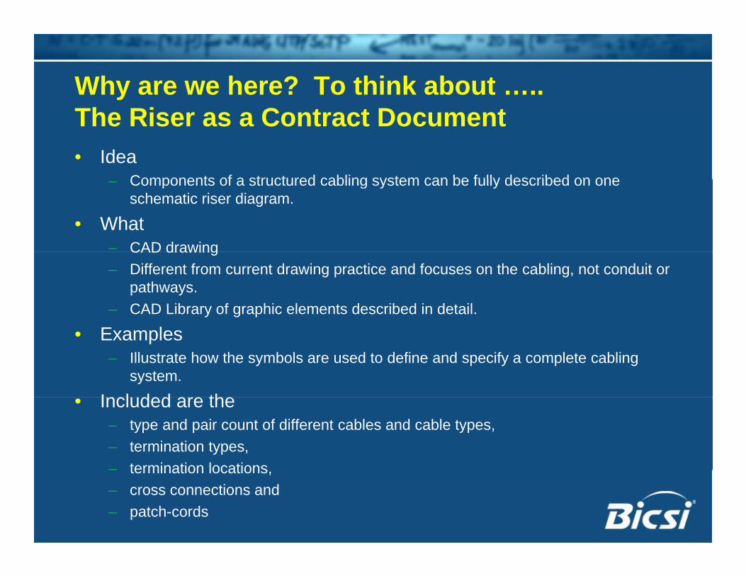
Why are we here? To think about …..The Riser as a Contract Document• Idea
Components of a structured cabling system can be fully described on one– Components of a structured cabling system can be fully described on one schematic riser diagram.
• What– CAD drawingCAD drawing– Different from current drawing practice and focuses on the cabling, not conduit or
pathways. – CAD Library of graphic elements described in detail.
• Examples– Illustrate how the symbols are used to define and specify a complete cabling
system.
I l d d th• Included are the – type and pair count of different cables and cable types, – termination types, – termination locations– termination locations, – cross connections and – patch-cords

What will we learn? ObjectivesWhat will we learn? Objectives– Context of a construction contract– Legal nature of a contract– Establish need for clarity and completenessy– Identify key documents for structured cabling– Identify use of LAYOUT PLANSy– Identify proper use of SPECIFICATIONS– Identify use of SCHEMATIC RISERIdentify use of SCHEMATIC RISER– How to prepare a RICH DETAIL FORMAT
(RDF) RISER SCHEMATIC( )
CONTRACT DOCUMENTSPart 2
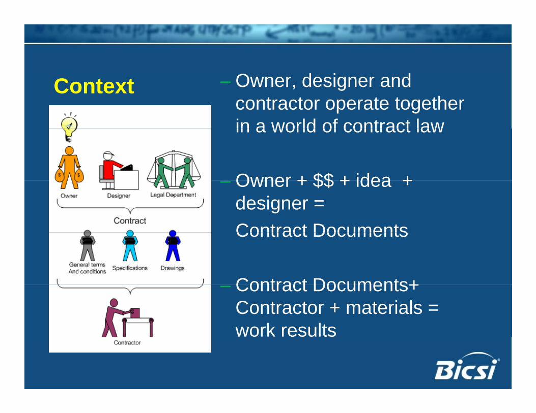
O d i dContext – Owner, designer and contractor operate together in a world of contract lawin a world of contract law
Owner + $$ + idea +– Owner + $$ + idea + designer = Contract DocumentsContract Documents
Contract Documents+– Contract Documents+ Contractor + materials = work results
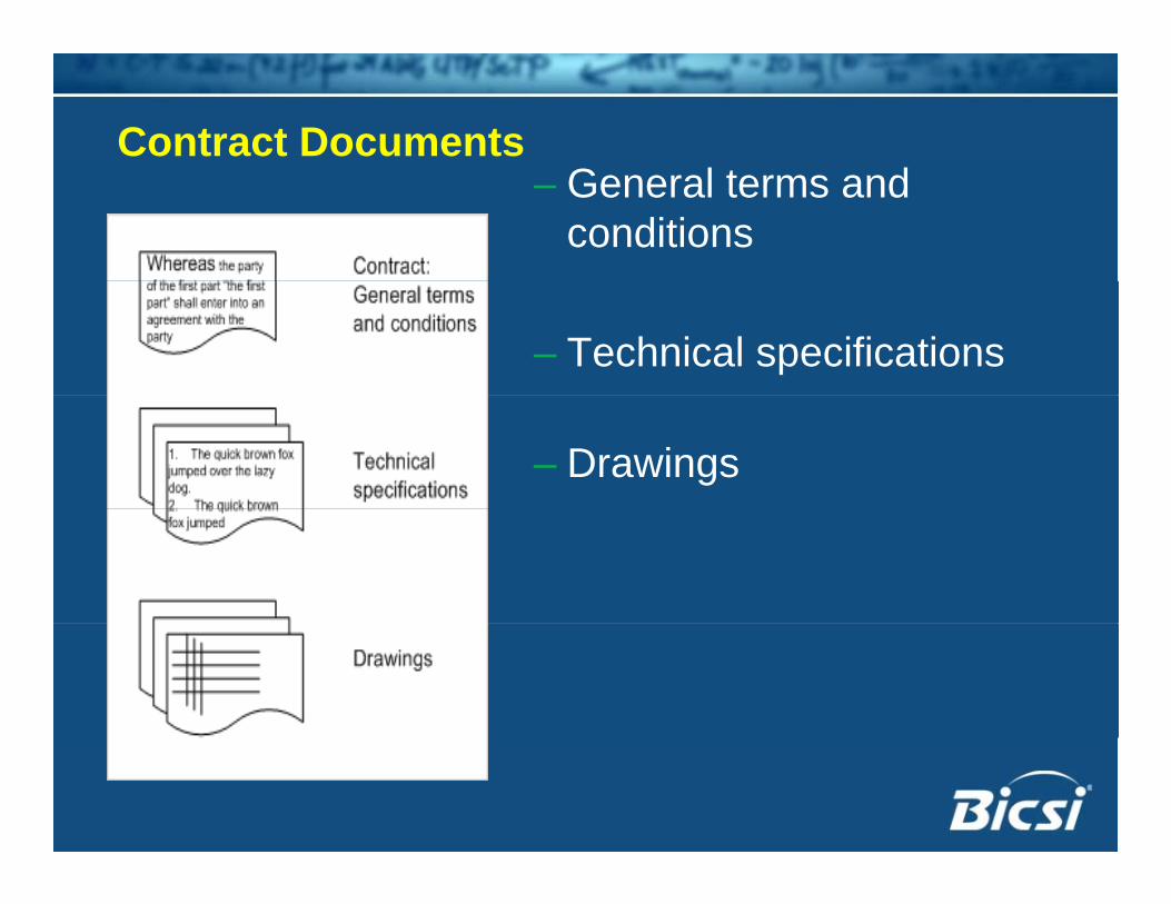
Contract DocumentsG– General terms and conditions
– Technical specifications
– Drawings

P d P U f C t t D tPurpose and Proper Use of Contract Documents
• General terms and conditions– Establishes relationship between the
Contractor and the Owner– Details the do’s and don’ts of the work– Sets up contract as p Construction Management (CM) or General Contract (GC)
– CM or GC can affect way Data cabling is sub-contracted

• SpecificationsPurpose and Proper Use of Contract Documents
p– Legally reinforces what is on the drawings– Defines scope of workp– Defines material components
• Designer will use specifications toE d f k– Expand on scope of work
– Detail desired components– Describes special execution of work

P d P U f C t t D t
• Specification split by description of Work
Purpose and Proper Use of Contract Documents
p p y p– Does NOT separate work by trade
• Specific areas of interest to this subjectSpecific areas of interest to this subject– Division 26 – Electrical rough in Communications pathways; supports cablingCommunications pathways; supports cabling
– Division 27 – Communications Structured cablingStructured cabling
– Division 28 – Security/Safety Uses structured cablingg

Division 27 - Communications• General description of workp
– What is included and excluded– Look for “Provide” or “Install” or “Furnish”.
• Definitions of Cable type and performance– Cable type and performance
– Connector type and performanceStandards for execution/installation– Standards for execution/installation
– Testing and test reporting

Correct use of drawings- layouts• Communications layout drawingsy g
– Outside plant shows conduits and site routing
– Inside plant Outlets – positions and jack count Telecommunications rooms Conduit and tray (sometimes)
• Contractor responsible for– Take off - quantity

Correct use of drawings- elevations
• Communications elevation drawingsg– Communications rooms Identifies racking Identifies wall layouts Identifies cable routing

Correct use of drawings- riser• Communications Riser drawingsg
– Describes the fixed link– Details outside and inside cablingg– Details connector types Copperpp Optical fibre
– Details mounting locationsg Rack Wall

Three parts to the contract documents• Layouty
– Describes placement/quantity of outlets– Shows pathwaysp y
• SpecificationsDefines products and designer’s wants– Defines products and designer s wants
• RiserD ib th bli i f t t– Describes the cabling infrastructure

Which document is the most valuable resource?
THE RISER SCHEMATICPart 3

Start with TIA 568.C.0
DISTRIBUTOR A (DA) HORIZONTAL CROSS-CONNECTFLOOR DISTRIBUTOR
DISTRIBUTOR B (DB) ( )INTERMEDIATE CROSS-CONNECT
DISTRIBUTOR C (DC) MAIN CROSS-CONNECT
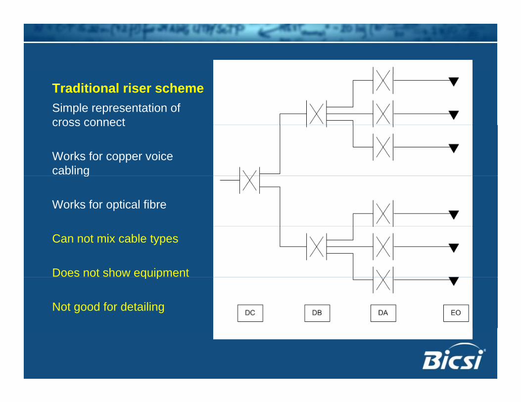
Traditional riser schemeSimple representation of cross connectcross connect
Works for copper voice cablingg
Works for optical fibre
Can not mix cable types
Does not show equipmentq p
Not good for detailing

Cross-connect +Cross connect + equipmentNew symbol needed to separate…separate…
BackboneEquipmentDistributionDistribution
What kind of terminations?IDC?IDC?Patch panel?
What kind of connections?What kind of connections?Cross-connect?Interconnect?

Traditional +Traditional + equipmentDrawing becomes crowded
No space to add detail
Suitable only for one cable type.
Better approach needed

DEVELOPING A NEW RISER SCHEMATICPart 4

DISTRIBUTOR A:DISTRIBUTOR A:THE CROSS-CONNECT

1. Refine the symbolVertical lines become generic terminationgeneric termination strips
Identify withIdentify withB – BackboneE – EquipmentD – Distribution
Cross lines eliminatedCross lines eliminated
Horizontal lines represent cablesrepresent cables

2. Show cabling
Back bone cables
Distribution cables
Indicate outlet jack

3. Add cabling terminations
Open symbols t RJ45represent RJ45
jacks

4. Add patch cords
Solid symbols t RJ45represent RJ45
plugs
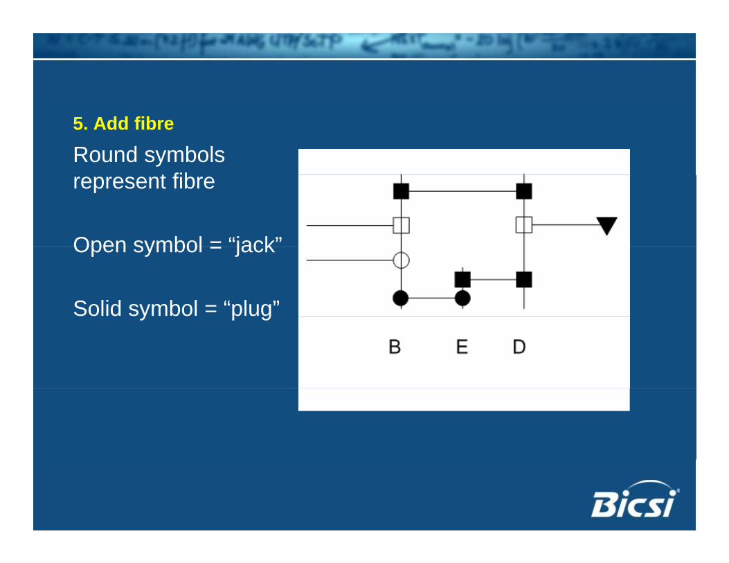
5. Add fibre
Round symbols t fibrepresent fibre
Open symbol = “jack”Open symbol = jack
Solid symbol = “plug”y p g
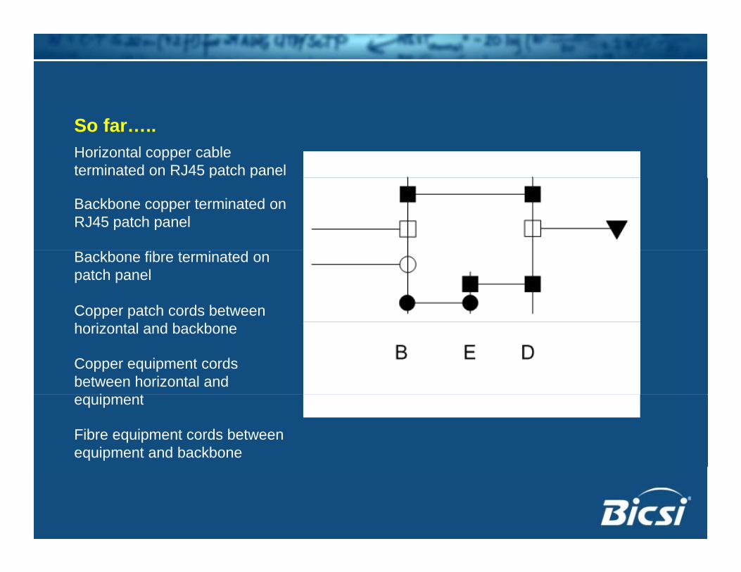
So far…..Horizontal copper cable terminated on RJ45 patch panelp p
Backbone copper terminated on RJ45 patch panel
Backbone fibre terminated on patch panel
Copper patch cords between horizontal and backbone
Copper equipment cords between horizontal and
i tequipment
Fibre equipment cords between equipment and backbone

6. Copper terminations at 110/BIXARROW symbol for 110/BIX punch-down110/BIX punch-down
Terminate TELEPHONE at 110/BIX IDC stripat 110/BIX IDC strip
Terminate TELEPHONE backbone on 110/BIX IDC strip
Show cross-connect between 110/BIX IDC strips

7. Separating termination locations
Separate WALL and RACK t i tiRACK terminations
BW=Backbone/WallBW=Backbone/WallBR=Backbone/Rack
DW=Distribution/WallDR=Distribution/Rack

8. Converged services
Crossover copper ticonnection
Link between RACKLink between RACK and WALL for backbone copper

9. Common outlet
ONE outlet for two iservices
RED path for voiceRED path for voice
BLUE path for datap

Summary: In the Telecom RoomSummary: In the Telecom Room• Symbolic representation fory p
– Copper cabling and terminations 110/BIX AND patch panel
– Optical fibre cabling and terminations– Wall and rack mountingg– Equipment– Patch/cross-connect cordsPatch/cross connect cords

BACKBONE CONNECTIONSBACKBONE CONNECTIONS
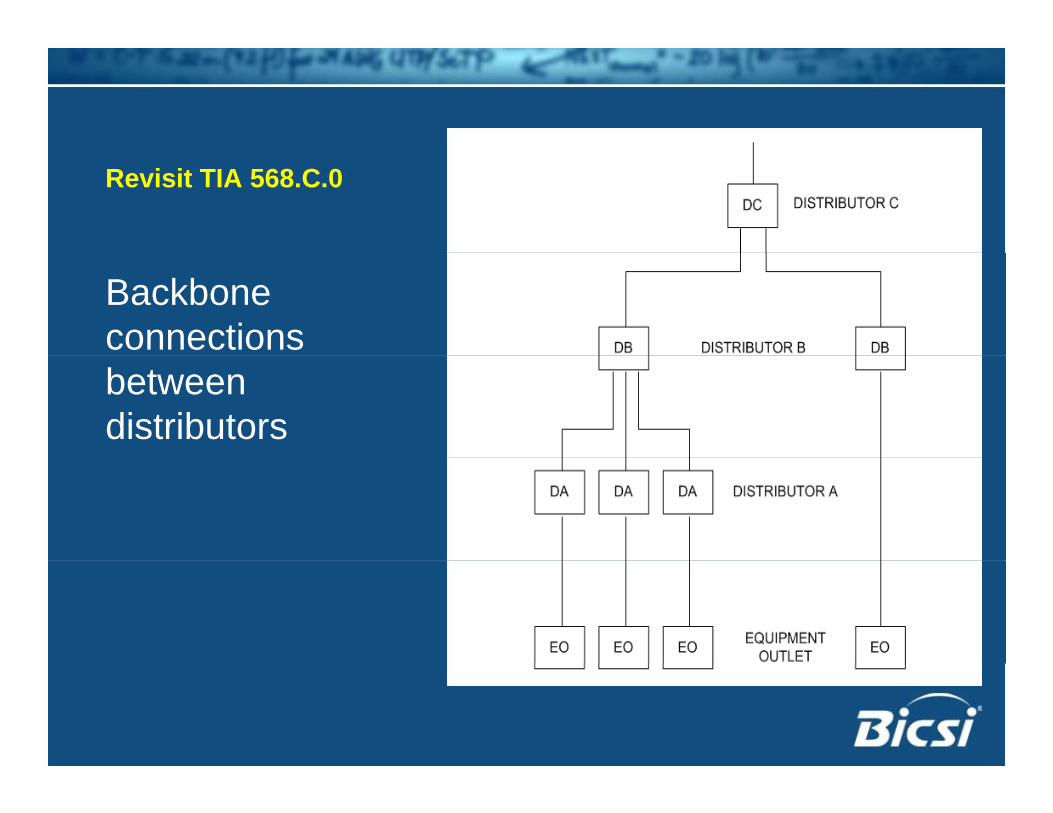
Revisit TIA 568.C.0
Backbone connections between distributors

Distributor connections
This is our new t ti i tstarting point
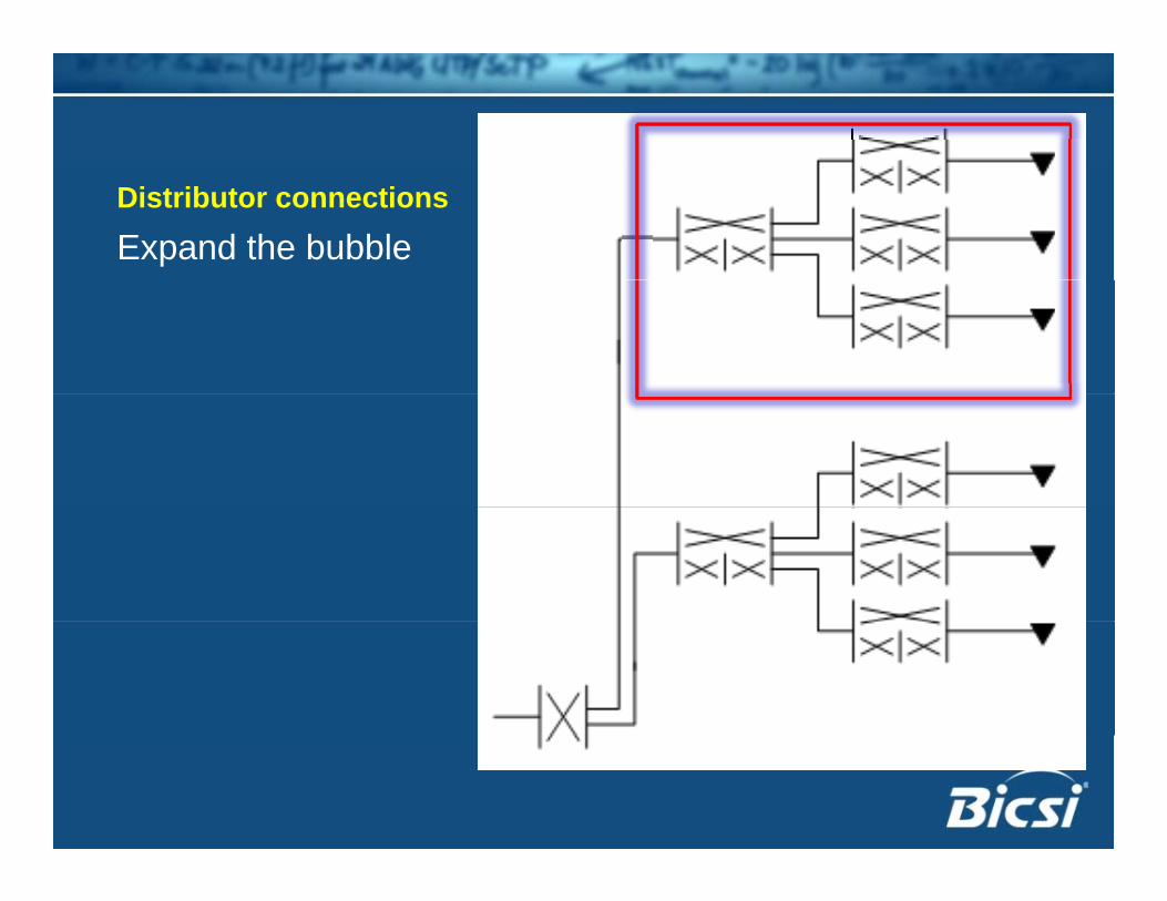
Distributor connections
Expand the bubble
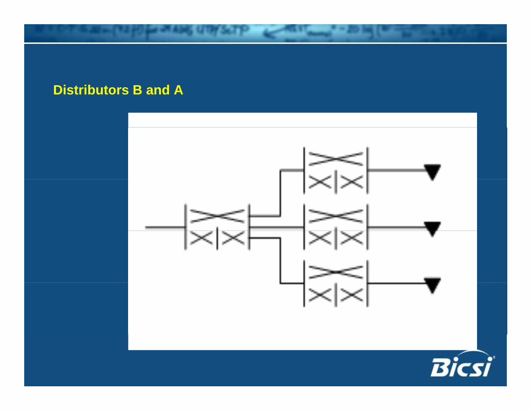
Distributors B and A

Backbone cables between distributors

Step 1: Replace OLD symbol with NEWStep 1: Replace OLD symbol with NEWNote: Distributor B has equipment but no horizontal distribution

Step 2: Extend the backbone between Distributor A and Distributor BDistributor A and Distributor B
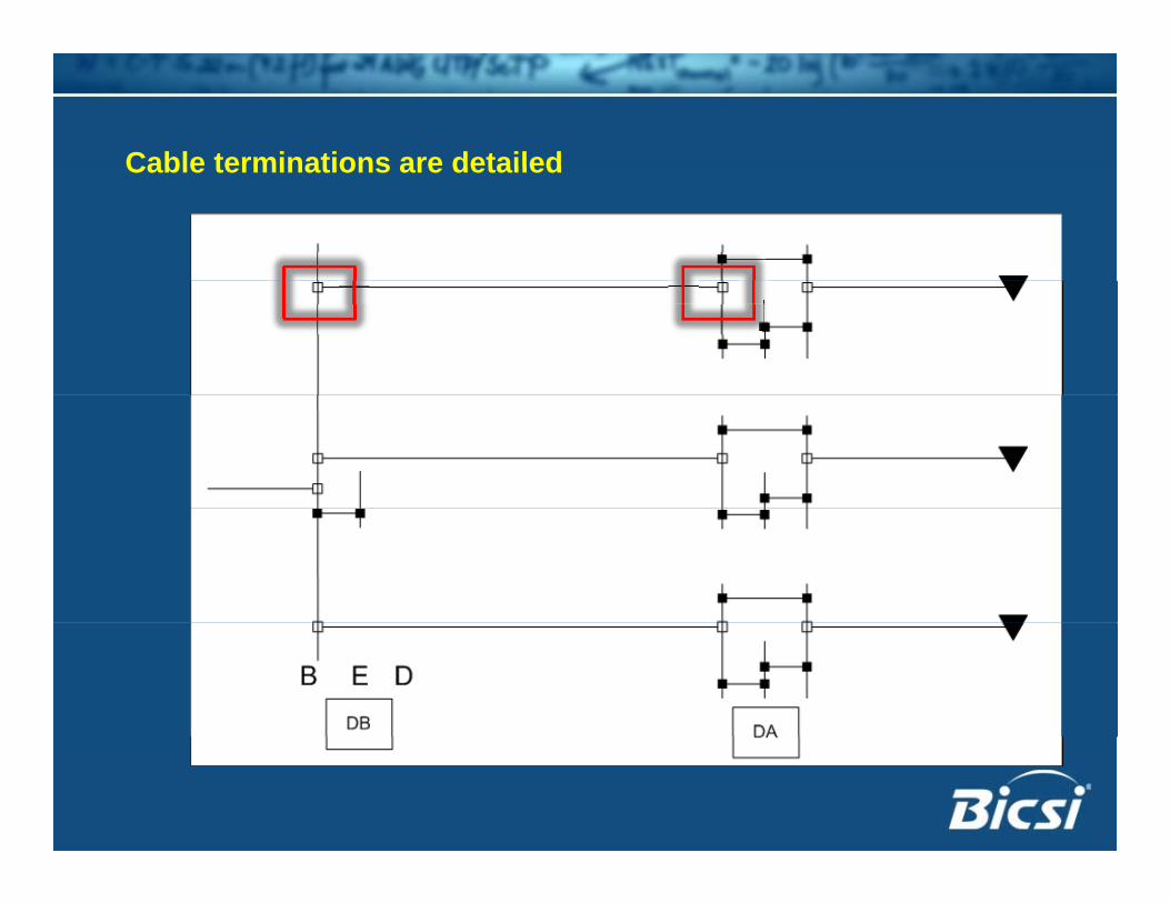
Cable terminations are detailedCable terminations are detailed
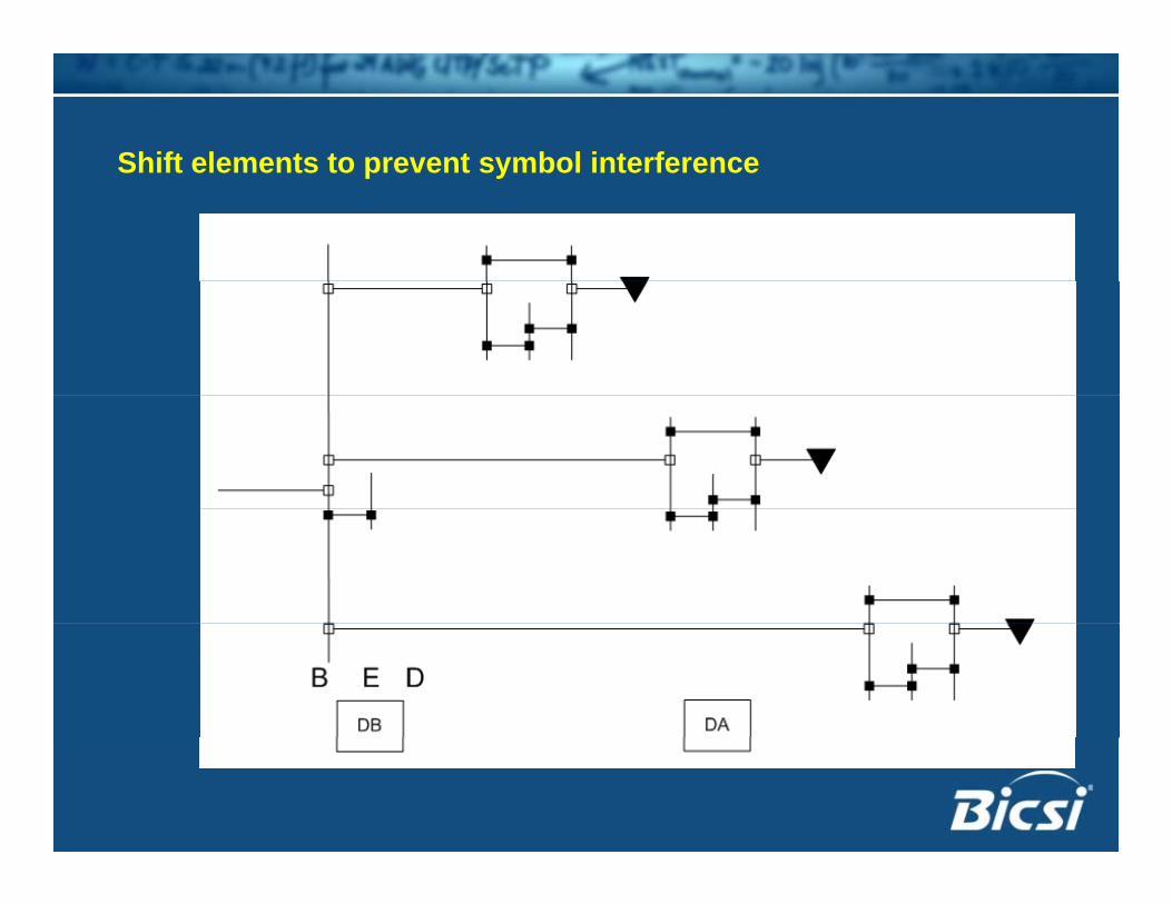
Shift elements to prevent symbol interferenceShift elements to prevent symbol interference

Clean up: tighten symbolsClean up: tighten symbolsGroup backbone cables together

Add fibre to backbone and equipmentAdd fibre to backbone and equipment(Symbols are exaggerated for clarity)

Add legend: Component details and room locationsAdd legend: Component details and room locations

Contract documentContract document
• Cable: – types, quantity
• Termination;Termination; – types, locations
• Quantities and formats defined
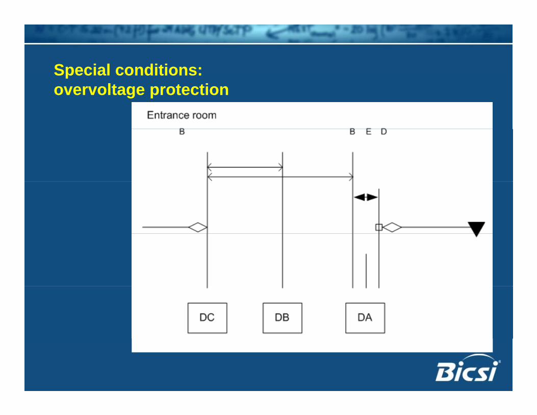
Special conditions: povervoltage protection
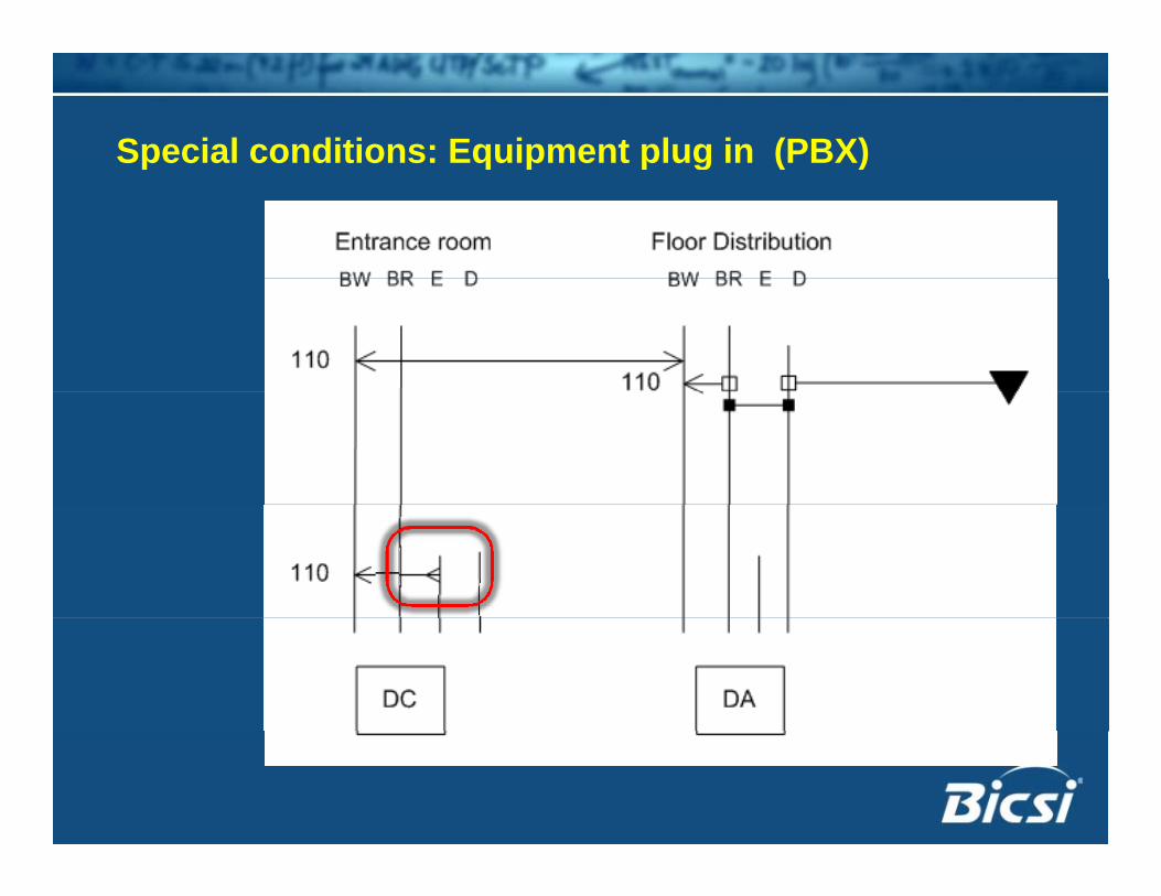
Special conditions: Equipment plug in (PBX)p q p p g ( )

Special conditions: Equipment plug in (PBX)p q p p g ( )

Symbols usedSymbols used
EXAMPLESPart 5
EXAMPLES

Sample: full riser schematicSample: full riser schematic

Focus area: Entrance and backbonesFocus area: Entrance and backbones

Building entranceBuilding entrance Copper backbone – 110 terminations - diverse routing
Building entrance
Diverse backboneentrance backbone pathways

Focus: distribution terminationsFocus: distribution terminations

Focus: distribution terminationsFocus: distribution terminations
Outlets in two work areas to common
patch panel
Pay phones run back to 110 in entrance
room
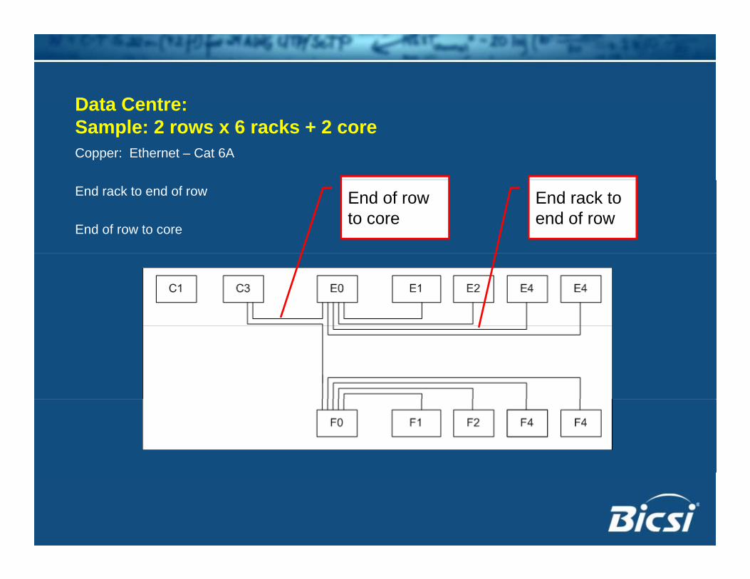
Data Centre:Data Centre: Sample: 2 rows x 6 racks + 2 coreCopper: Ethernet – Cat 6A
End rack to end of row
End of row to core
End rack to end of row
End of row to core

Data Centre:Data Centre: Sample: 2 rows x 6 racks + 2 coreFibre Channel + Ethernet
Admin point 1
Two administration points
End of row to core
End of row to core
Admin point 2

Data centre:Data centre: All cables + terminations: One diagram

Data centre:Data centre:Context
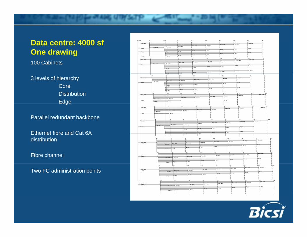
Data centre: 4000 sfData centre: 4000 sfOne drawing100 Cabinets
3 levels of hierarchyCoreDistributionEdgeg
Parallel redundant backbone
Ethernet fibre and Cat 6AEthernet fibre and Cat 6A distribution
Fibre channel
Two FC administration points
CONCLUSIONPart 6
CONCLUSION
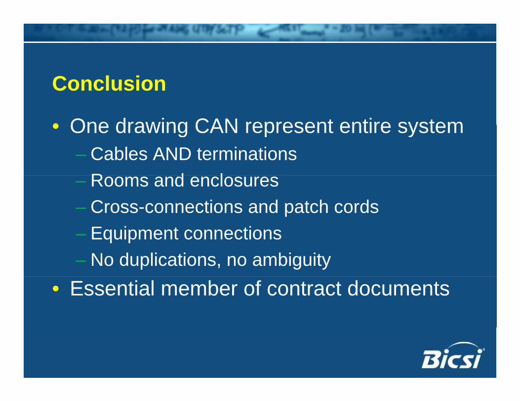
Conclusion
• One drawing CAN represent entire system• One drawing CAN represent entire system– Cables AND terminations
R d l– Rooms and enclosures– Cross-connections and patch cords– Equipment connections– No duplications, no ambiguity
• Essential member of contract documents

The Riser as a Contract Document