Embed Size (px)
Citation preview
1 Copyright © 2016 by modkitsdiy.com
Use these instructions to learn:
How to build an effects pedal for fuzz and octave-up fuzz.
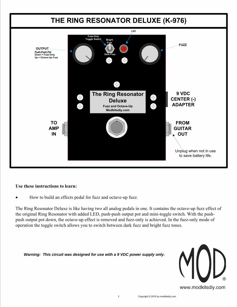
The Ring Resonator Deluxe is like having two all analog pedals in one. It contains the octave-up fuzz effect of the original Ring Resonator with added LED, push-push output pot and mini-toggle switch. With the push-push output pot down, the octave-up effect is removed and fuzz-only is achieved. In the fuzz-only mode of operation the toggle switch allows you to switch between dark fuzz and bright fuzz tones.
THE RING RESONATOR DELUXE (K-976)
Warning: This circuit was designed for use with a 9 VDC power supply only.
TO AMP
IN
FROM GUITAR
OUT
Unplug when not in use to save battery life.
The Ring ResonatorDeluxe
Modkitsdiy.com
Push-Push PotDown = Fuzz-OnlyUp = Octave-Up Fuzz
FUZZ
Fuzz and Octave-Up
9 VDCCENTER (-) ADAPTER
OUTPUT
LED
Bright Fuzz
Fuzz-Only Toggle Switch
Dark Fuzz
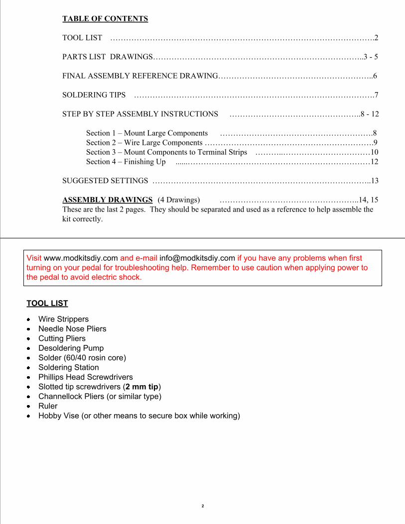
TABLE OF CONTENTS
TOOL LIST ……………………………………………………………………………………….2
PARTS LIST DRAWINGS……………………………………………………………………..3 - 5
FINAL ASSEMBLY REFERENCE DRAWING…………………………………………………..6
SOLDERING TIPS ……………………………………………………………………………….7
STEP BY STEP ASSEMBLY INSTRUCTIONS …………………………………………..8 - 12
Section 1 – Mount Large Components ………………………………………………….8Section 2 – Wire Large Components ……………………………………………………….9Section 3 – Mount Components to Terminal Strips ………..……………………………10Section 4 – Finishing Up ......……………………………………………………………12
SUGGESTED SETTINGS ………………………………………………………………………..13
ASSEMBLY DRAWINGS (4 Drawings) ……………………………………………..14, 15These are the last 2 pages. They should be separated and used as a reference to help assemble the kit correctly.
2
Visit www.modkitsdiy.com and e-mail [email protected] if you have any problems when first turning on your pedal for troubleshooting help. Remember to use caution when applying power to the pedal to avoid electric shock.
TOOL LIST
Wire StrippersNeedle Nose PliersCutting PliersDesoldering PumpSolder (60/40 rosin core)Soldering StationPhillips Head ScrewdriversSlotted tip screwdrivers (2 mm tip)Channellock Pliers (or similar type)RulerHobby Vise (or other means to secure box while working)
Enclosure P-H1590BBCE-BK (1)
Knob, Black with Silver TopP-K392 (2)
Battery ClipS-H155 (1)
¼” Mono Jack (Output Jack)W-SC-11 (1)
¼” Stereo Jack (Input Jack)W-SC-12B (1)
Stranded Wire (22 AWG) - RedK-PUL1569 (4 FT)
PARTS LIST 1
3
RING LUG
SLEEVE LUG
TIP LUG
SLEEVE LUG
TIP LUG
Potentiometers: 1KL and 500KAR-VA1KL (1)R-VPSH-500KA (1)
#4 Screw (3/8" long)S-HS440-38 (7)
#4 NutS-HHN440 (7)
#4 Lock WasherS-HLW4 (7)
Terminal Strip with 8 TerminalsP-0802H (2)
DC Power JackS-H750 (1)
Terminal Strip with 3 TerminalsP-0301H (1)
Terminal Strip with 5 TerminalsP-0501H (2)
3PDT Foot SwitchP-H501 (1)
500KA1KL
1
2
3
4
5
6
PARTS LIST 2
4
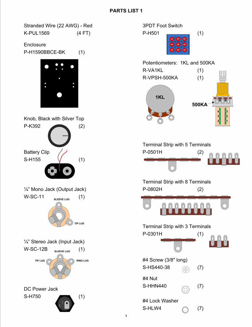
Audio Transformer (1.5K : 600 Ω)P-T42TM022 (1)
150500V
150pF Capacitor 500VC-SM150 (1)
0.1µF Capacitor 100VC-PEID1-100 (1)
104J
0.001µF Capacitor 100VC-PEID001-100 (1)
102J
Light Emitting Diode P-L400 (1)
+-
P-Q2N5088 (2)NPN BJT (2N5088)
MPSA18
E B C
K-PQ-2N3906 (1)PNP BJT (2N3906)
2N3906
E B C
P-Q972 (2)Germanium Diode (1N34A)
C-ET100-25-IL (2)100µF Polarized Capacitor 25V
100µF 25V
33µF Polarized Capacitor 50V
33µF 50VC-ET33-50 (2)
SPDT Mini Toggle Switch
P-H540 (1)
50500V
50pF Capacitor 500VC-SM50 (1)
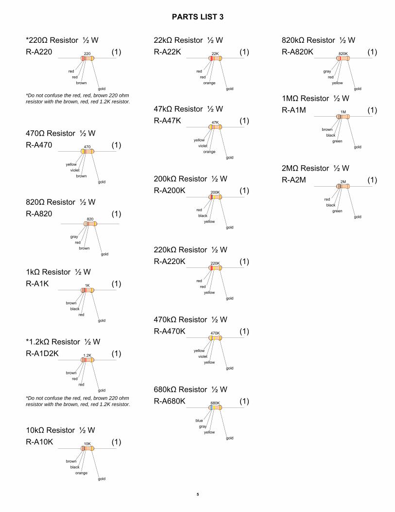
PARTS LIST 3
5
redred
yellowgold
220K
220kΩ Resistor ½ WR-A220K (1)
bluegray
yellowgold
680K
680kΩ Resistor ½ WR-A680K (1)
grayred
yellowgold
820K
820kΩ Resistor ½ WR-A820K (1)
brownblack
greengold
1M
1MΩ Resistor ½ WR-A1M (1)
yellowviolet
yellowgold
470K
470kΩ Resistor ½ WR-A470K (1)
brownblack
redgold
1K
1kΩ Resistor ½ WR-A1K (1)
redred
orangegold
22K
22kΩ Resistor ½ WR-A22K (1)
yellowviolet
orangegold
47K
47kΩ Resistor ½ WR-A47K (1)
redblack
yellowgold
200K
200kΩ Resistor ½ WR-A200K (1)
brownblack
orangegold
10K
10kΩ Resistor ½ WR-A10K (1)
yellowviolet
browngold
470
470Ω Resistor ½ WR-A470 (1)
grayred
browngold
820
820Ω Resistor ½ WR-A820 (1)
redred
browngold
220
*220Ω Resistor ½ WR-A220 (1)
*Do not confuse the red, red, brown 220 ohm resistor with the brown, red, red 1.2K resistor.
brownred
redgold
1.2K
*1.2kΩ Resistor ½ WR-A1D2K (1)
*Do not confuse the red, red, brown 220 ohm resistor with the brown, red, red 1.2K resistor.
redblack
greengold
2M
2MΩ Resistor ½ WR-A2M (1)
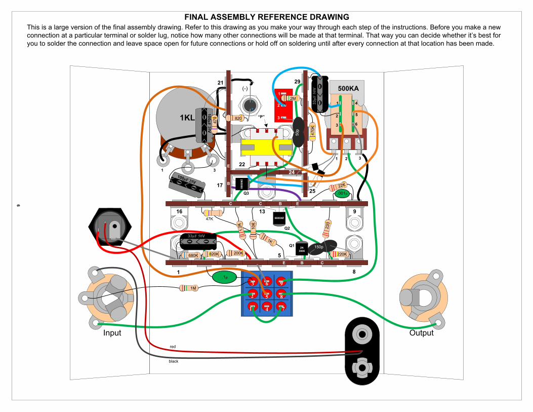
FINAL ASSEMBLY REFERENCE DRAWINGThis is a large version of the final assembly drawing. Refer to this drawing as you make your way through each step of the instructions. Before you make a new connection at a particular terminal or solder lug, notice how many other connections will be made at that terminal. That way you can decide whether it’s best for you to solder the connection and leave space open for future connections or hold off on soldering until after every connection at that location has been made.
6
-+
2
3
1
6
5
4
1
2
3
1KL
(-) 500KA
9
8
7
1 2 3
1
2
3
4
5
6
1
2
3
1 8
916
17
21
22
29
25
5
13
24
1
2
3
1M
.1µ
820K 200K680K 220K
150p
220
2N3906
Q1
E B C
1K
.001µ
22K
2N5088
EBC
Q21.2K
47K
100µF 25V
E
B
C
Q3
2N5088
33µF 50V
100µF
25V
470 “P”820
10K
33µ
F 5
0V
2M
470K
50p
red
black
Input Output
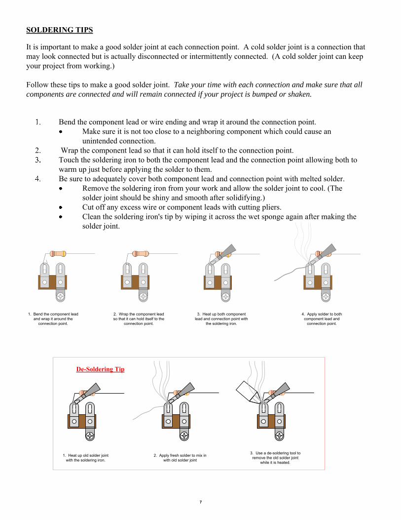
SOLDERING TIPS
1. Bend the component lead and wrap it around the
connection point.
2. Wrap the component lead so that it can hold itself to the
connection point.
3. Heat up both component lead and connection point with
the soldering iron.
4. Apply solder to both component lead and
connection point.
2. Apply fresh solder to mix in with old solder joint
1. Heat up old solder joint with the soldering iron.
3. Use a de-soldering tool to remove the old solder joint
while it is heated.
De-Soldering Tip
7
It is important to make a good solder joint at each connection point. A cold solder joint is a connection that may look connected but is actually disconnected or intermittently connected. (A cold solder joint can keep your project from working.)
Follow these tips to make a good solder joint. Take your time with each connection and make sure that all components are connected and will remain connected if your project is bumped or shaken.
Bend the component lead or wire ending and wrap it around the connection point.Make sure it is not too close to a neighboring component which could cause an unintended connection.
2. Wrap the component lead so that it can hold itself to the connection point.Touch the soldering iron to both the component lead and the connection point allowing both to warm up just before applying the solder to them.Be sure to adequately cover both component lead and connection point with melted solder.
Remove the soldering iron from your work and allow the solder joint to cool. (The solder joint should be shiny and smooth after solidifying.)Cut off any excess wire or component leads with cutting pliers. Clean the soldering iron's tip by wiping it across the wet sponge again after making the solder joint.
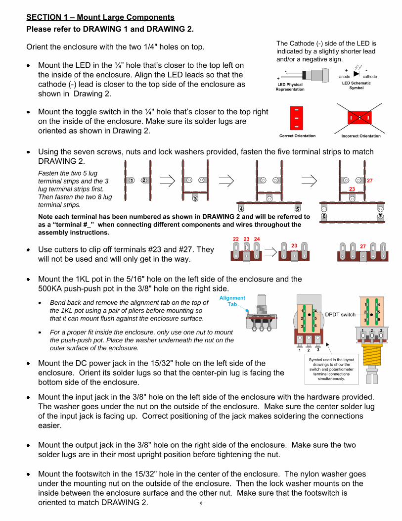
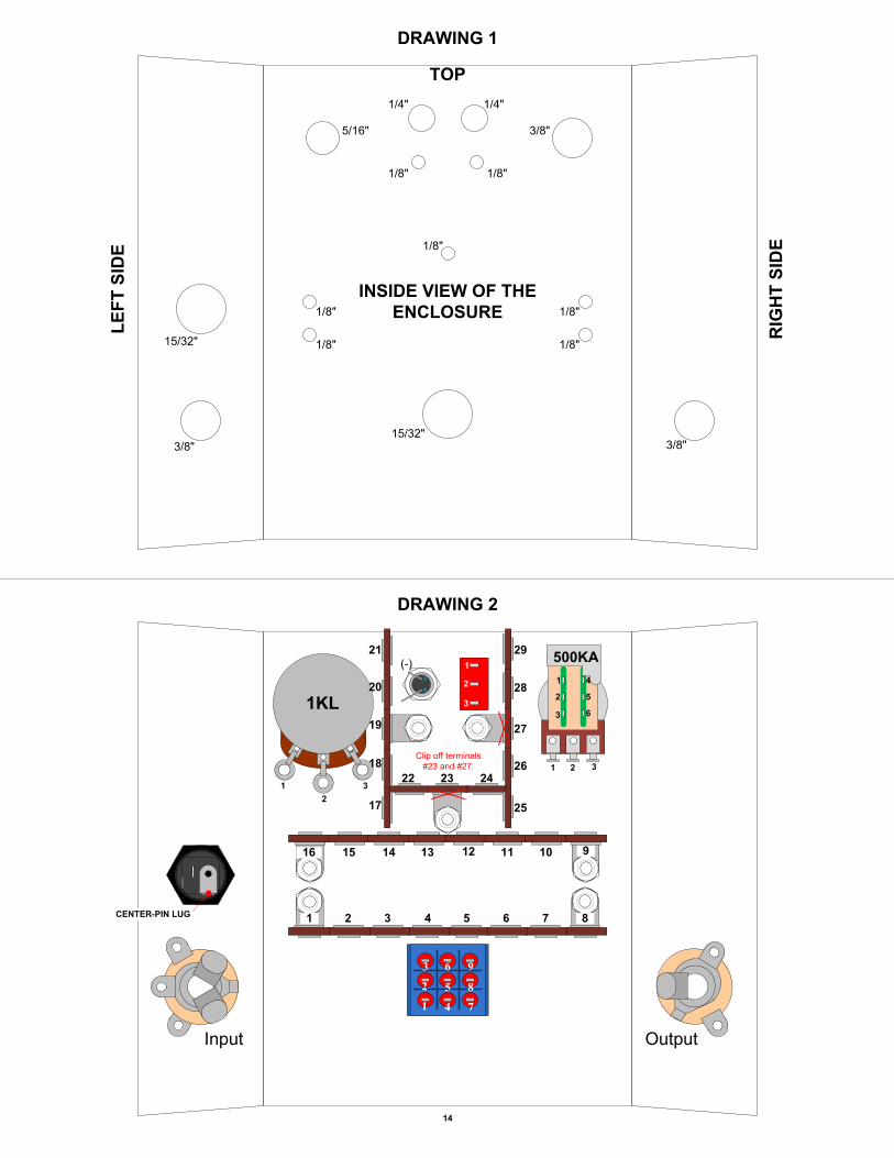
SECTION 1 – Mount Large ComponentsPlease refer to DRAWING 1 and DRAWING 2.
Orient the enclosure with the two 1/4" holes on top.
Using the seven screws, nuts and lock washers provided, fasten the five terminal strips to match DRAWING 2.Fasten the two 5 lug terminal strips and the 3 lug terminal strips first. Then fasten the two 8 lug terminal strips.
Mount the input jack in the 3/8" hole on the left side of the enclosure with the hardware provided. The washer goes under the nut on the outside of the enclosure. Make sure the center solder lug of the input jack is facing up. Correct positioning of the jack makes soldering the connections easier.
Mount the output jack in the 3/8" hole on the right side of the enclosure. Make sure the two solder lugs are in their most upright position before tightening the nut.
Mount the footswitch in the 15/32" hole in the center of the enclosure. The nylon washer goes under the mounting nut on the outside of the enclosure. Then the lock washer mounts on the inside between the enclosure surface and the other nut. Make sure that the footswitch is oriented to match DRAWING 2. 8
Mount the LED in the ¼” hole that’s closer to the top left on the inside of the enclosure. Align the LED leads so that the cathode (-) lead is closer to the top side of the enclosure as shown in Drawing 2.
The Cathode (-) side of the LED is indicated by a slightly shorter lead and/or a negative sign.
LED Physical Representation
+- + -
LED Schematic Symbol
anode cathode
Mount the toggle switch in the ¼" hole that’s closer to the top right on the inside of the enclosure. Make sure its solder lugs are oriented as shown in Drawing 2.
Mount the 1KL pot in the 5/16" hole on the left side of the enclosure and the 500KA push-push pot in the 3/8" hole on the right side.
Bend back and remove the alignment tab on the top of the 1KL pot using a pair of pliers before mounting so that it can mount flush against the enclosure surface.
Alignment Tab
Mount the DC power jack in the 15/32" hole on the left side of the enclosure. Orient its solder lugs so that the center-pin lug is facing the bottom side of the enclosure.
1 2 3
1
2
3
4
5
6
1
2
3
4
5
6
1 2 3
Symbol used in the layout drawings to show the
switch and potentiometer terminal connections
simultaneously.
DPDT switch
For a proper fit inside the enclosure, only use one nut to mount the push-push pot. Place the washer underneath the nut on the outer surface of the enclosure.
Note each terminal has been numbered as shown in DRAWING 2 and will be referred to as a “terminal #_” when connecting different components and wires throughout the assembly instructions.
Use cutters to clip off terminals #23 and #27. They will not be used and will only get in the way.
1 2
3
4 56 7
23
Correct Orientation Incorrect Orientation
272322 24
23
27
Stripping wire, tinning wire and soldering. Throughout these instructions you will be told to strip and tin a length of wire numerous times. Unless noted otherwise, cut the wire to the length stated in the instructions. Then strip ¼” of insulation off each end. Twist each end of the stranded wire, and apply a small amount of solder to each end (i.e. tin the wire ends). This will prevent the stranded wire from fraying and will make the final soldering much easier.
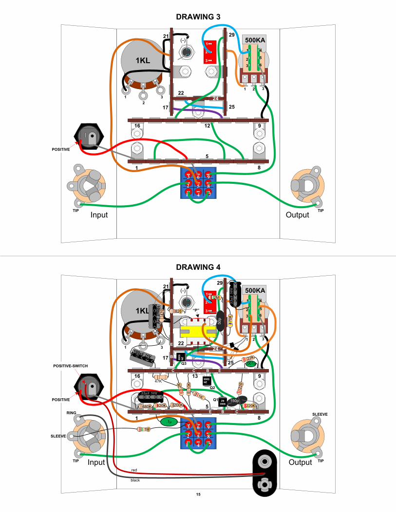
SECTION 2 – Wire Large ComponentsPlease refer to DRAWING 3.
9
Strip and tin a 2" piece of wire and connect Footswitch lug 8 to the output jack’s tip lug.
Strip and tin a 1 ½” piece of wire and connect Footswitch lugs 1 and 7 to each other.
Strip and tin a 2” piece of wire and connect Footswitch lug 2 to the input jack’s tip lug.
Strip and tin a 4" piece of wire and connect Footswitch lug 9 to the 500KA pot’s lug 2.
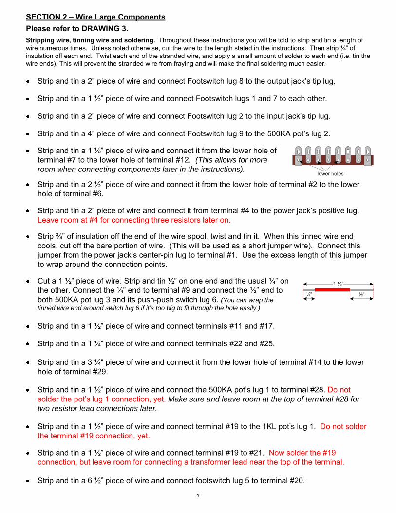
Strip and tin a 1 ½” piece of wire and connect it from the lower hole of terminal #7 to the lower hole of terminal #12. (This allows for more room when connecting components later in the instructions).
lower holes
Strip and tin a 2 ½” piece of wire and connect it from the lower hole of terminal #2 to the lower hole of terminal #6.
Strip and tin a 2" piece of wire and connect it from terminal #4 to the power jack’s positive lug. Leave room at #4 for connecting three resistors later on.
Strip ¾” of insulation off the end of the wire spool, twist and tin it. When this tinned wire end cools, cut off the bare portion of wire. (This will be used as a short jumper wire). Connect this jumper from the power jack’s center-pin lug to terminal #1. Use the excess length of this jumper to wrap around the connection points.
Cut a 1 ½” piece of wire. Strip and tin ½” on one end and the usual ¼” on the other. Connect the ¼” end to terminal #9 and connect the ½” end to both 500KA pot lug 3 and its push-push switch lug 6. (You can wrap the tinned wire end around switch lug 6 if it’s too big to fit through the hole easily.)
Strip and tin a 3 ¼" piece of wire and connect it from the lower hole of terminal #14 to the lower hole of terminal #29.
Strip and tin a 1 ½” piece of wire and connect terminals #11 and #17.
Strip and tin a 1 ¼” piece of wire and connect terminals #22 and #25.
Strip and tin a 1 ½” piece of wire and connect terminal #19 to the 1KL pot’s lug 1. Do not solder the terminal #19 connection, yet.
Strip and tin a 1 ½” piece of wire and connect terminal #19 to #21. Now solder the #19 connection, but leave room for connecting a transformer lead near the top of the terminal.
Strip and tin a 1 ½” piece of wire and connect the 500KA pot’s lug 1 to terminal #28. Do not solder the pot’s lug 1 connection, yet. Make sure and leave room at the top of terminal #28 for two resistor lead connections later.
1 ½”
¼” ½”
Strip and tin a 6 ½” piece of wire and connect footswitch lug 5 to terminal #20.
10
SECTION 3 – Mount Components to Terminal StripsPlease refer to DRAWING 4.Connect and solder all the following components to their respective terminals as listed. (Make sure that none of the component leads are so close together that it could cause an unintended short).
Connect the 680K resistor to terminals #1 and #2.
Connect the 0.1µF cap to terminal #2 and footswitch lug 3. Mount this cap upside down with its leads facing up. Do not solder the lug 3 connection, yet.
Connect the 1M resistor to footswitch lug 3 and the input jack’s sleeve lug. Now solder the footswitch lug 3 connection.
Double check all of your connections at this point because it will be difficult to make corrections after the components are soldered into place.
Strip and tin a 1" length of wire and connect the cathode (-) lead of the LED to terminal #21. (Connect the wire end and cathode lead by bending and crimping them around each other. Solder them once they are tightly connected to each other).
Strip and tin a 2 ½” piece of wire and connect push-push switch lug 1 to toggle switch lug 2. Do not solder the toggle switch lug 2 connection, yet. Route this wire along the top side of the enclosure so it does not get in your way while making connections at terminals #26 to #29.
Strip ¾” of insulation off the end of the wire spool, twist and tin it. When this tinned wire end cools, cut off the bare portion of wire. Connect this jumper from footswitch lug 6 to terminal #4. Leave room at #4 for connecting three resistors later on.
Connect the 820K resistor to terminals #2 and #3. Push this component down slightly to allow room for the next component. Do not solder the connection on terminal #3, yet.
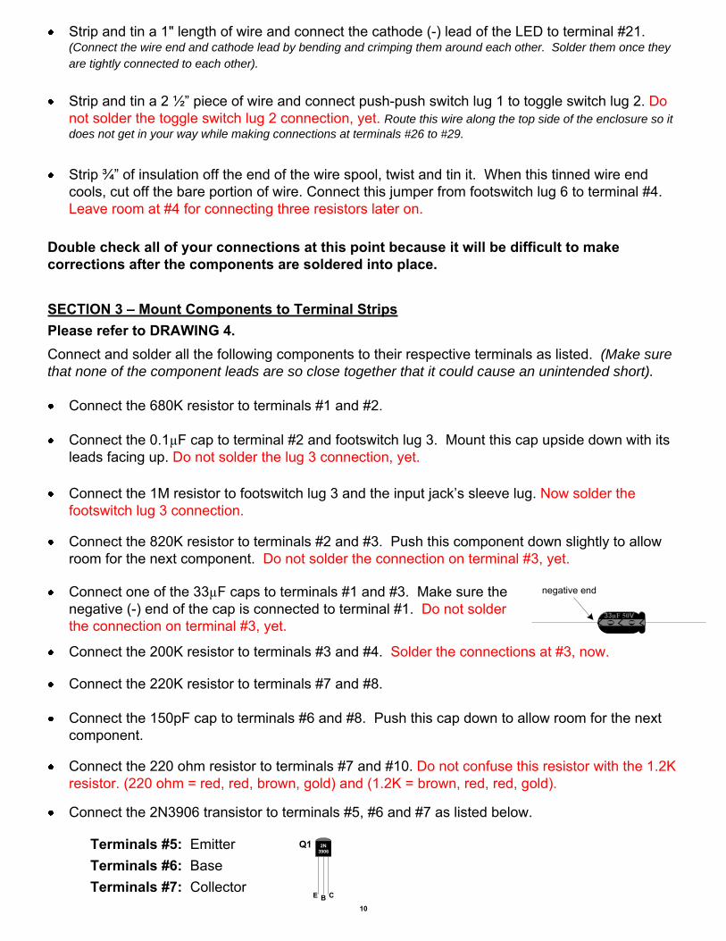
Connect one of the 33µF caps to terminals #1 and #3. Make sure the negative (-) end of the cap is connected to terminal #1. Do not solder the connection on terminal #3, yet.
33µF 50V
negative end
Connect the 200K resistor to terminals #3 and #4. Solder the connections at #3, now.
Connect the 220K resistor to terminals #7 and #8.
Connect the 150pF cap to terminals #6 and #8. Push this cap down to allow room for the next component.
Connect the 220 ohm resistor to terminals #7 and #10. Do not confuse this resistor with the 1.2K resistor. (220 ohm = red, red, brown, gold) and (1.2K = brown, red, red, gold).
Connect the 2N3906 transistor to terminals #5, #6 and #7 as listed below.
Terminals #5: EmitterTerminals #6: BaseTerminals #7: Collector
2N3906
E B C
Q1
11
Connect the 1K resistor to terminal #5 and #15.
Connect the .001µF cap to terminals #9 and #10.
Connect the 22K resistor to terminals #9 and #11.
Connect one of the 2N5088 transistors to terminals #11, #12 and #13 as listed below.
Terminals #11: EmitterTerminals #12: BaseTerminals #13: Collector
2N5088
E B C
Connect the 1.2K resistor to terminals #4 and #14. Leave room on #14 for mounting Q3 later.
Connect the 47K resistor to terminals #14 and #15. Leave room on #14 for mounting Q3 later.
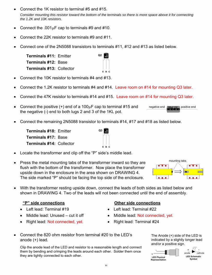
Connect the positive (+) end of a 100µF cap to terminal #15 and the negative (-) end to both lugs 2 and 3 of the 1KL pot.
100µF 25Vnegative end positive end
Connect the remaining 2N5088 transistor to terminals #14, #17 and #18 as listed below.
Terminals #14: CollectorTerminals #17: BaseTerminals #18: Emitter 2N
5088
E B C
Locate the transformer and clip off the “P” side’s middle lead.
mounting tabs
Connect the 10K resistor to terminals #4 and #13.
Consider mounting this resistor toward the bottom of the terminals so there is more space above it for connecting the 1.2K and 10K resistors.
With the transformer resting upside down, connect the leads of both sides as listed below and shown in DRAWING 4. Two of the leads will not been connected until the end of assembly.
“P” side connectionsLeft lead: Terminal #19Middle lead: Unused – cut it offRight lead: Not connected, yet.
Other side connectionsLeft lead: Terminal #22Middle lead: Not connected, yet.Right lead: Terminal #24
Press the metal mounting tabs of the transformer inward so they are flush with the bottom of the transformer. Now place the transformer upside down in the enclosure in the area shown on DRAWING 4. The side marked “P” should be facing the top side of the enclosure.
Q2
Q3
Connect the 820 ohm resistor from terminal #20 to the LED’s anode (+) lead.
The Anode (+) side of the LED is indicated by a slightly longer lead and/or a positive sign.
LED Physical Representation
+- + -
LED Schematic Symbol
anode cathode
Clip the anode lead of the LED and resistor to a reasonable length and connect them by bending and crimping the leads around each other. Solder them once they are tightly connected to each other.
12
Connect the remaining 33µF cap from the push-push pot’s switch lug 2 to terminal #29. Make sure the negative (-) end is connected to lug 2.
Connect one of the 1N34A diodes from terminal #24 to the 500KA pot lug 1, but do not solder at lug 1, yet. Make sure the black (cathode) end connects to lug 1.
cathode endanode end
Connect the remaining 1N34A diode from terminal #25 to 500KA pot lug 1 with the cathode end at lug 1. Now solder the pot’s lug 1 connection.
SECTION 4 – Finishing Up
Attach the knobs provided to the two potentiometer shafts. Install 9 volt battery, close cover using screws provided. Plug guitar into input jack on right. This turns unit on. Plug cable into output jack and plug into your amplifier.
Unplug from the input jack of the unit to turn it off and save power.
It’s always a good idea to thoroughly double-check your connections before applying power.
Locate the battery snap connector. Connect and solder the red lead to the positive-switch lug of the power jack.
RING LUG
SLEEVE LUG
TIP LUG
Input JackConnect and solder the black lead of the battery snap connector to the input jack’s ring lug.
POSITIVE-SWITCH LUG
Connect the 2M resistor from toggle switch lug 2 to terminal #28 leaving space on the terminal for another resistor lead connection. Now solder the toggle switch lug 2 connection.
Connect the 50pF cap from toggle switch lug 3 to terminal #26.
Connect the 470K resistor from terminal #26 to #28. Leave room for the 50 pF cap as shown in DRAWING 4.
Connect the 470 ohm resistor to terminals #18 and #21.
Connect the remaining 100µF cap to terminals #18 and #21. Make sure the negative (-) end is connected to #21.
100µF 25Vnegative end
“P” Connect to push-push switch lug 3 with a 2” wire.
Connect to push-push switch lug 5 with a 2 ½” wire.
Connect the two remaining disconnected transformer leads to their respective push-push switch lugs as shown in DRAWING 4. Clip the leads to about ¼” and make small hooks in the lead ends that can hook in with their respective wire ends.
Fastening the knob onto the push-push pot can be tricky. Just make sure the bottom of the knob’s brass insert is lined up with, and not sitting lower than, the bottom lip of the pot shaft. Otherwise, the switch will not be able to change settings when pressed down.
Correct positioning of the knob’s brass
insert on the shaft.
1Down
2Pressed
Down
3Up
Bottom lip of the pot shaft.
Bottom of the brass insert.
Set Screw (Use 2 mm flat tip screw driver.)
Knob
Tip: It’s easier to fasten the knob and see where the brass insert lines up when the shaft is in the up position.
FUZZBright Fuzz
Dark Fuzz
“(I Can’t Get No) Satisfaction” LeadOUTPUT
(Down)Output: 1 o’clock
Fuzz: 2 o’clock
Toggle: Up (Bright Fuzz)
Push-Push Pot: Down
Suggested Settings
Guitar Pickup: Bridge
FUZZBright Fuzz
Dark Fuzz
“Purple Haze” LeadOUTPUT
(Up)Output: 5 o’clock (max)
Fuzz: 10 o’clock
Toggle: not active
Push-Push Pot: Up
Suggested Settings
Guitar Pickup: Neck
FUZZBright Fuzz
Dark Fuzz
“American Woman” LeadOUTPUT
(Down)Output: 10 o’clock
Fuzz: 5 o’clock (max)
Toggle: Down (Dark Fuzz)
Push-Push Pot: Down
Suggested Settings
Guitar Pickup: Neck
7o’clock
5 o’clock
12 o’clock
9 3
10
11 1
2
48
7o’clock
5 o’clock
12 o’clock
9 3
10
11 1
2
48
min max min max
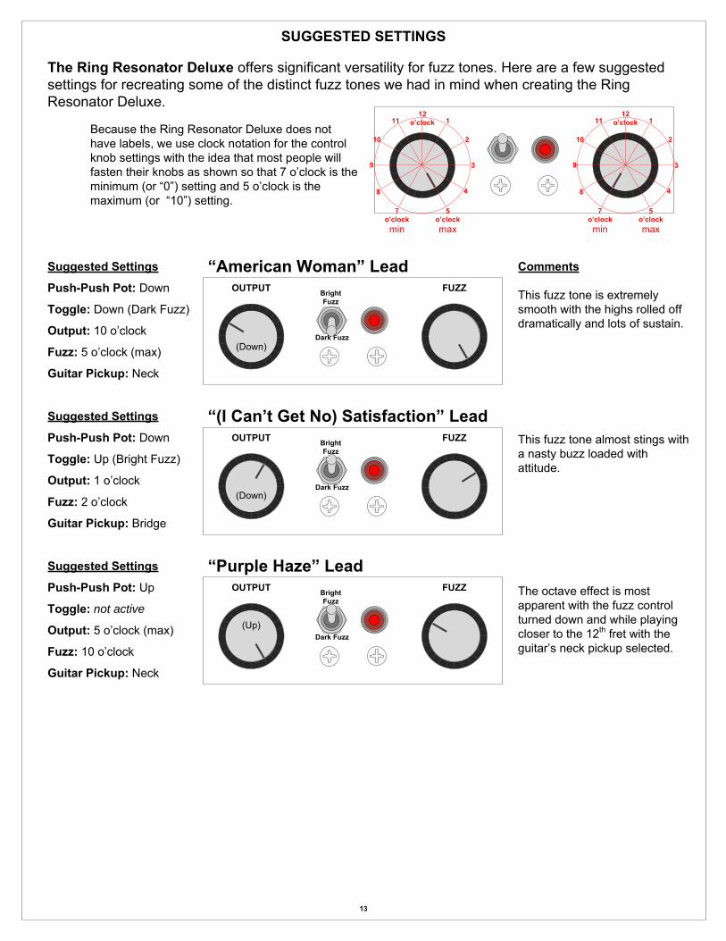
The Ring Resonator Deluxe offers significant versatility for fuzz tones. Here are a few suggested settings for recreating some of the distinct fuzz tones we had in mind when creating the Ring Resonator Deluxe.
SUGGESTED SETTINGS
Comments
Because the Ring Resonator Deluxe does not have labels, we use clock notation for the control knob settings with the idea that most people will fasten their knobs as shown so that 7 o’clock is the minimum (or “0”) setting and 5 o’clock is the maximum (or “10”) setting.
This fuzz tone is extremely smooth with the highs rolled off dramatically and lots of sustain.
This fuzz tone almost stings with a nasty buzz loaded with attitude.
The octave effect is most apparent with the fuzz control turned down and while playing closer to the 12th fret with the guitar’s neck pickup selected.
13
-+
2
3
1
6
5
4
12
3
DRAWING 1
TOP
LEFT
SID
E
RIG
HT
SID
E
INSIDE VIEW OF THE ENCLOSURE
DRAWING 2
1KL
14
15/32"
1/8"1/8"
1/8" 1/8"
1/8"
1/8"1/8"
3/8"3/8"
15/32"
3/8"5/16"
1/4"1/4"
(-) 500KA
9
8
7
1 2 3
1
2
3
4
5
6
CENTER-PIN LUG 1
12
2 3 4 5 6 7 8
9101113141516
17
18
19
20
21
22 23 24
25
26
27
28
29
Input Output
1
2
3
Clip off terminals #23 and #27.
DRAWING 3
DRAWING 4
15
-+
2
3
1
6
5
4
12
3
1KL
(-) 500KA
9
8
7
1 2 3
1
23
4
5
6
1
2
3
1 8
916
17
21
22
29
25
5
12
TIPTIPInput Output
POSITIVE
24
1
2
3
-+
2
3
1
6
5
4
12
3
1KL
(-) 500KA
9
8
7
1 2 3
1
23
4
56
1
2
3
1 8
916
17
21
22
29
25
5
13
TIPTIP
POSITIVE
24
1
2
3
1M
.1µ
820K 200K680K 220K150p
220
2N3906
Q1
E B C
1K
.001µ22K
2N5088
EBC
Q21.2K
47K
100µF 25V
E
B
C
Q3
2N5088
33µF 50V
100µF
25V
470 “P”820
10K
POSITIVE-SWITCH
33µ
F 5
0V
2M
470K
50p
red
black
Input Output
SLEEVE
RING SLEEVE


![Improved Split-Ring Resonator for Microfluidicorca.cf.ac.uk/59763/1/Improved split ring.pdf · 2020. 11. 26. · The resonant frequency of a cavity resonator [13] is set by its dimensions,](https://img.pdfslide.us/doc/110x75/60f99d8762b1d658425e30d9/improved-split-ring-resonator-for-split-ringpdf-2020-11-26-the-resonant.jpg)