Embed Size (px)
Citation preview
FACULTY OF ENGINEERING AND SUSTAINABLE DEVELOPMENT .
Design of Singly Split Single Ring Resonator for
Measurement of Dielectric Constant of Materials using
Resonant Method
Jabita,A.A
June 2013
Master’s Thesis in Electronics and Telecommunications
Master’s Program in Electronics/Telecommunications
Examiner: Prof. Jose Chilo
Supervisor: Prof. Kjell Prytz


Jabita,A.A Design of Singly Split Single Ring Resonator for Measurement of Dielectric Constant
of Materials using Resonant Method
i
Jabita,A.A Design of Singly Split Single Ring Resonator for Measurement of Dielectric Constant
of Materials using Resonant Method
ii
Preface
This thesis is part of the numerous research projects being worked on by my lecturer,Professor Kjell
Prytz.The project is challenging and motivating,it requires one to learn fast in short period,it gives a
better understanding and importance of dielectric properties of materials,it also improves ones deftness
in the use of HFSS and VNA.
I thank Professor Kjell Prytz for giving me this project to execute;I thank Professor Jose Chilo for his
objective and constructive criticism, and I also thank Mr Rickard Larsson for cutting the ring resonator
and the MUT into specified geometries.
“I thank all members of my family for their inestimable support through my study years,never could I
have a better family.And to my daughter,and my wife,you shall do better ones than this.”
Jabita,A.A

Jabita,A.A Design of Singly Split Single Ring Resonator for Measurement of Dielectric Constant
of Materials using Resonant Method
iii
Abstract
Scientists and engineers measure dielectric constant because it gives them better understanding of
materials and helps them to know how to integrate these materials into their design processes;it also
helps them to shorten design life cycle,and aside these two functions,it has numerous uses all of which
cannot be enumerated in this section.Owing to its usefulness,various measurement methods of
dielectric constant of materials have been developed over the years.Each method has its limitations
which affect the accuracy of the measurement;these limitations range from frequency,temperature,and
mearsurement environment to material under test.
In this thesis,four most common methods of measuring dielectric constant were discussed and the
most accurate one,the resonant method,was chosen and worked on .The project was executed by
making a mathematical analysis of the ring resonator which was later simulated in HFSS to get results
which would be comparable to ones obtained in laboratory measurements.
The ring was fabricated and taken to the laboratory for measurement.Two monopole antennas were
connected to the two ports of a VNA with one antenna serving as the transmitter and the other serving
as the receiver.
The resonant frequencies obtained were combined with the geometric parameters of the ring resonator
and that of the MUT in equations written into MATLAB scripts;this equations were used to extract the
dielectric constant of the MUT.
Jabita,A.A Design of Singly Split Single Ring Resonator for Measurement of Dielectric Constant
of Materials using Resonant Method
iv
Jabita,A.A Design of Singly Split Single Ring Resonator for Measurement of Dielectric Constant
of Materials using Resonant Method
v
Table of contents
Preface ..................................................................................................................................................... ii
Abstract .................................................................................................................................................. iii
Table of contents ..................................................................................................................................... v
1 Introduction ..................................................................................................................................... 9
1.1 Objective ............................................................................................................................... 10
1.2 Outline of the Project ............................................................................................................ 10
2 Theory ........................................................................................................................................... 11
2.1 Dielectric Constant ................................................................................................................ 11
2.2 Significance of Dielectric Constant Measurement ................................................................ 11
2.3 Dielectric Constant Measurement Methods .......................................................................... 12
2.3.1 Coaxial Probe Method ................................................................................................... 12
2.3.2 Transmission Line Method ............................................................................................ 13
2.3.3 Free space Method ......................................................................................................... 14
2.3.4 Resonant Cavity Method ............................................................................................... 14
2.4 Resonant Methods versus Broadband Methods .................................................................... 15
2.5 Comparison of Measurement Methods ................................................................................. 15
2.6 Vector Network Analyser(VNA) .......................................................................................... 16
2.7 Monopole Antenna ................................................................................................................ 17
2.8 Resonator ............................................................................................................................... 17
2.8.1 Resonance ...................................................................................................................... 18
2.8.2 Uses of Resonator .......................................................................................................... 19
2.8.3 Types of resonators ....................................................................................................... 19
2.8.4 The Split Ring Resonator .............................................................................................. 19
2.9 High Frequency Structure Simulator(HFSS) ......................................................................... 20
3 Process and results......................................................................................................................... 21
3.1 Thesis Flowchart ................................................................................................................... 21
3.2 Analysis of SRR .................................................................................................................... 22
Jabita,A.A Design of Singly Split Single Ring Resonator for Measurement of Dielectric Constant
of Materials using Resonant Method
vi
3.3 Simulation of SRR................................................................................................................. 26
3.3.1 Excitation and Boundaries in HFSS .............................................................................. 27
3.3.2 Simulated resonant frequencies without and with MUT in the gap .............................. 29
3.4 Measurement with SRR ......................................................................................................... 33
4 Discussion ..................................................................................................................................... 37
5 Conclusions ................................................................................................................................... 39
References ............................................................................................................................................. 40
Appendix A ............................................................................................................................................. 1
Jabita,A.A Design of Singly Split Single Ring Resonator for Measurement of Dielectric Constant
of Materials using Resonant Method
vii
List of Figures
Chapter 2
Figure 2. 1:A parallel plate capacitor .................................................................................................. 11
Figure 2. 2:Coaxial Probe Measurement Method ................................................................................ 12
Figure 2. 3:Transmission Line Measurement Method .......................................................................... 13
Figure 2. 4:Free Space Measurement Method ...................................................................................... 14
Figure 2. 5:Resonant Cavity Method .................................................................................................... 15
Figure 2.6:Comparison of Dielectric Measurement Methods............................................................... 16
Figure 2. 7:Schema of a Vector Network Analyser ............................................................................... 16
Figure 2. 8:Radiation Pattern and physical structure of a Monopole Antenna .................................... 17
Figure 2.9:An LC Circuit ...................................................................................................................... 18
Figure 2. 10:A Series and a Parallel LC Resonant Cicuits .................................................................. 18
Figure 2. 11:common stuctures of split ring resonator ......................................................................... 20
Chapter 3
Figure 3. 1:The Thesis Process ............................................................................................................. 21
Figure 3. 2:Geometries of the ring under analysis ............................................................................... 22
Figure 3. 3:Ring Resonator Model without MUT ................................................................................. 26
Figure 3. 4:PerfectH Boundary of Ring Resonator Model in HFSS ..................................................... 27
Figure 3. 5:PerfectE Boundary of Ring Resonator Model in HFSS ..................................................... 27
Figure 3. 6:Port 1 of Ring Resonator Model in HFSS .......................................................................... 28
Figure 3. 7:Port 2 of Ring Resonator Model in HFSS .......................................................................... 28
Figure 3. 8:S11/S21 vs f0 from 0.5-15GHZ for the Ring resonator without the material. .................... 29
Figure 3. 9:Simulated S11/S21 vs f0 from 0.5-2.5GHZ for the Ring resonator without the material. .. 29
Figure 3. 10:S11/S21 vs f0 from 0.5-15GHZ for the Ring resonator with the material (Porcelain). ... 30
Figure 3. 11:Ring Resonator with Porcelain material in the gap. ........................................................ 31
Figure 3. 12:Simulated S11/S21 vs f0 from 0.5-2.5GHZ for the Ring resonator with material
(Porcelain);the frequency shifted from 1.64GHZ to 1.39GHZ. ............................................................ 31
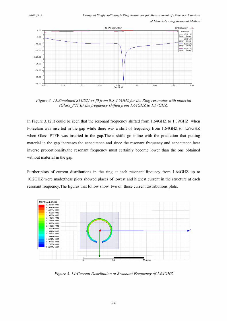
Figure 3. 13:Simulated S11/S21 vs f0 from 0.5-2.5GHZ for the Ring resonator with material
(Glass_PTFE);the frequency shifted from 1.64GHZ to 1.57GHZ......................................................... 32
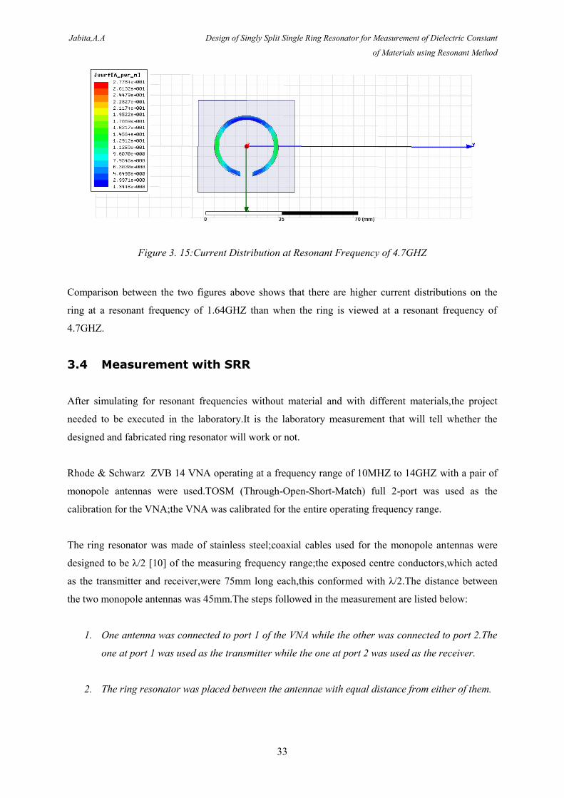
Figure 3. 14:Current Distribution at Resonant Frequency of 1.64GHZ ............................................... 32
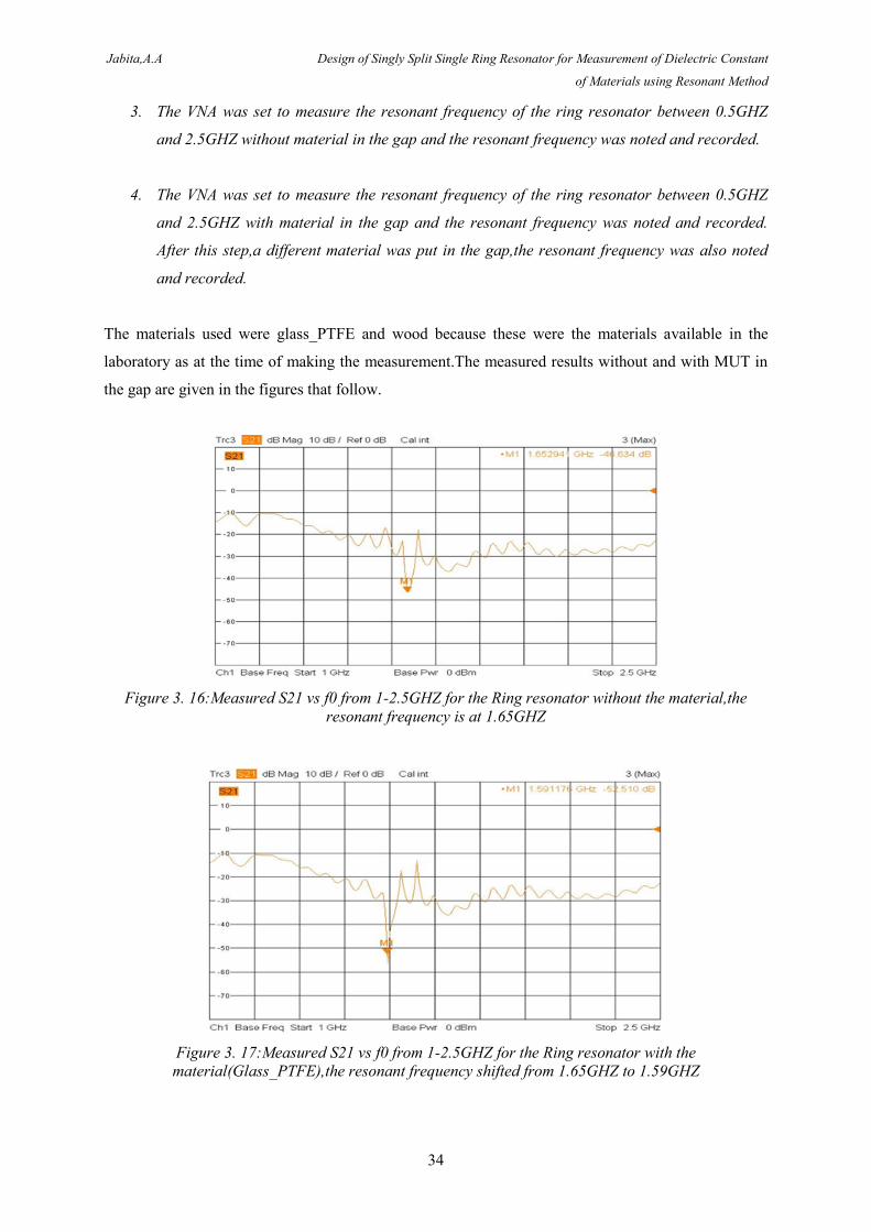
Figure 3. 15:Current Distribution at Resonant Frequency of 4.7GHZ ................................................. 33
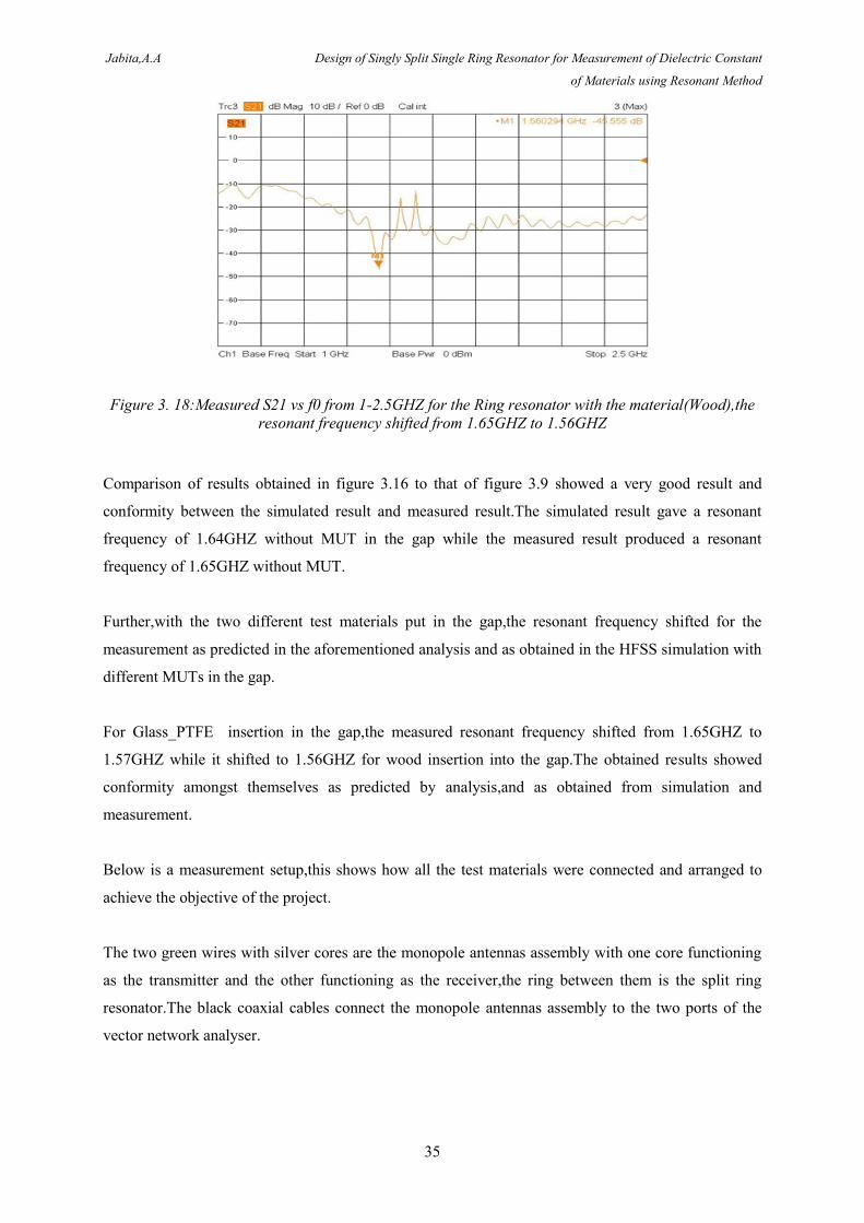
Figure 3. 16:Measured S21 vs f0 from 1-2.5GHZ for the Ring resonator without the material,the
resonant frequency is at 1.65GHZ ........................................................................................................ 34
Jabita,A.A Design of Singly Split Single Ring Resonator for Measurement of Dielectric Constant
of Materials using Resonant Method
viii
Figure 3. 17:Measured S21 vs f0 from 1-2.5GHZ for the Ring resonator with the
material(Glass_PTFE),the resonant frequency shifted from 1.65GHZ to 1.59GHZ ............................ 34
Figure 3. 18:Measured S21 vs f0 from 1-2.5GHZ for the Ring resonator with the material(Wood),the
resonant frequency shifted from 1.65GHZ to 1.56GHZ ........................................................................ 35
Figure 3. 19:Measurement Setup .......................................................................................................... 36
List of Tables
Chapter 4
Table 4. 1:Resonant frequency results obtained from analysis,simulation,and measurement .............. 37
Table 4. 2:Resonant frequencies and Dielectric constants obtained from simulation with MUT in the
gap ......................................................................................................................................................... 37
Table 4. 3:Resonant frequenciess and Dielectric constants obtained from measurement with MUT in
the gap ................................................................................................................................................... 37
Jabita,A.A Design of Singly Split Single Ring Resonator for Measurement of Dielectric Constant
of Materials using Resonant Method
9
1 Introduction
In microwave circuit design,material science,biological research,absorber development ,e.t.c, the
measurement of dielectric properties of materials at radio frequencies has gathered a huge interest.The
importance of this measurement stems from the fact that it gives insights into the electrical or
magnetic characteristics of materials and these characteristics have great amount of uses in the
research and development fields.
Various methods abound for the measurement of dielectric properties of materials with each method
limited to certain frequencies,applications,materials,e.t.c.Of the numerous methods available,Coaxial
Probe Method,Transmission Line Method,Free space Method,and Resonant Cavity Method are the
most popular and these are the ones that will be briefly discussed in Chapter 2 of this thesis.
Measuring dielectric properties of materials means measuring the complex relative permittivity,εr and
the complex relative permeability,μr .Both the real and imaginary parts are present in a complex
dielectric permittivity;the real part of the complex dielectric permittivity is called the dielectric
constant.When an external electric field is applied to a material,there is some energy loss,the measure
of this energy loss from the material because of the applied external electric field is the dielectric
constant.The imaginary and real parts of the complex permittivity have a ratio called the loss tangent,it
is written as tanδ ;it is also called dissipation factor,tangent loss,and loss factor[1].
The complex permeability also has both the real and imaginary parts.When an external magnetic field
is applied to a material,the materials stores some amount of energy and also dissipates some,this stored
energy represents the real part of the permeability while the complex part represents the dissipated
energy.As majority of materials are non-magnetic,their permeabilities border on that of free space.
Given the importance of dielectric constant in industry design cycles,process monitoring,and quality
assurance,dielectric constant measurement needs to be accurate to enhance quality and productivity
and as such,this project aims to ease the measurement of dielectric constant of materials in a simple
but accurate way by using a single ring resonator device .
The method used is Resonant Method where a shift in resonant frequency is combined with the
geometric parameters of the ring in order to extract the dielectric constant of the material under test
(MUT).
Jabita,A.A Design of Singly Split Single Ring Resonator for Measurement of Dielectric Constant
of Materials using Resonant Method
10
Since accuracy is paramount,Resonant Method was chosen because it is very accurate in extracting the
dielectric constant of materials;it is also economical because it supports small samples of MUT.
1.1 Objective
The aim of this thesis is to measure,as accurately as possible,the dielectric constant of materials (solid
materials) using the Resonant Method.The ring resonator will be simulated as well as fabricated so
that there could be two means of results,viz simulation,and measurement.At the end,these two results
will be compared for similarities and disimilarities.
1.2 Outline of the Project
Chapter 1 talks about Introduction to the project.
Chapter 2 focuses on the Theory behind the thesis.
Chapter 3 is on the different Processes and the Results obtained.
Chapter 4 is about Discussion of the results.
Chapter 5 is on Conclusion.
Jabita,A.A Design of Singly Split Single Ring Resonator for Measurement of Dielectric Constant
of Materials using Resonant Method
11
2 Theory
Here,the state of knowledge upon which the constituent parts of the thesis are based were addressed.
Dielectric Constant,Significance of Dielectric Constant Measurement,Dielectric Constant
Measurement Methods,Resonant Methods versus Broadband Methods,Comparison of Measurement
Methods,Vector Network Analyser(VNA),Monopole Antenna,Resonator,High Frequency Structure
Simulator(HFSS) were briefly discussed.
2.1 Dielectric Constant
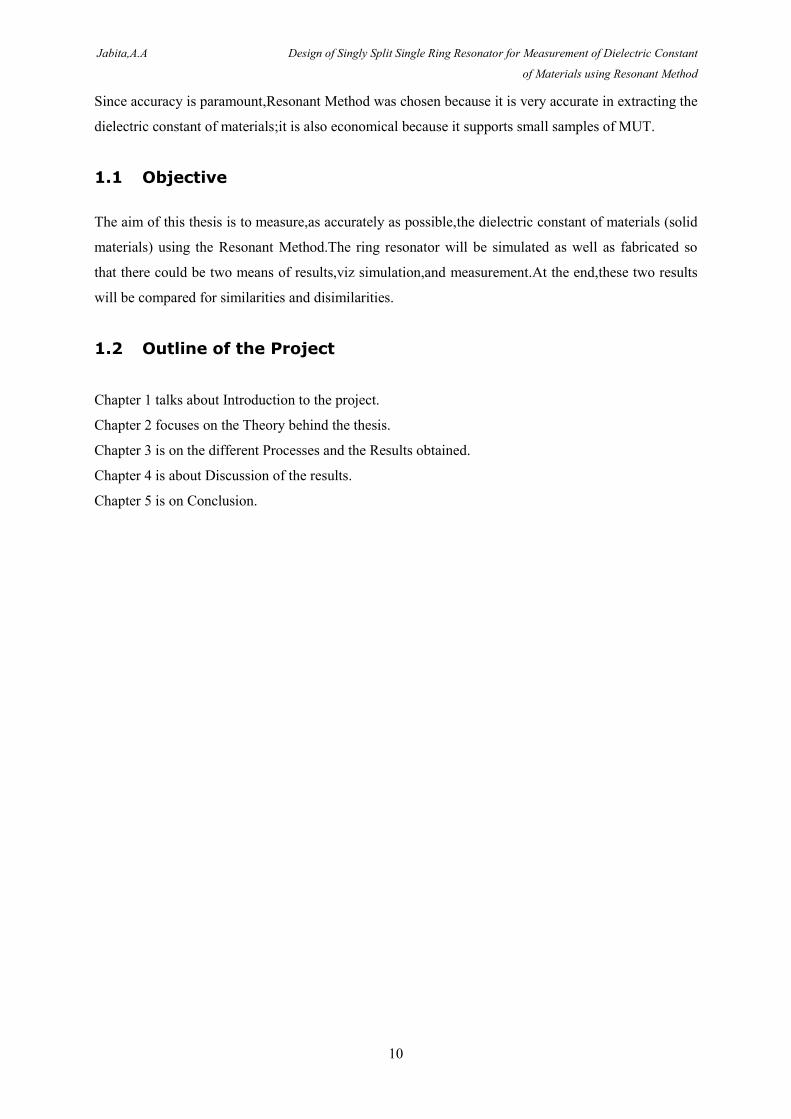
If a material has the capability to store energy when an external electric field is applied to it,then that
material is called a dielectric.If there is a parallel plate capacitor with a DC voltage source across its
plates,the capacitor stores more charges with a dielectric material between the plates than when there
is no material(when there is vacuum) between the plates.
From Figure 2.1 below,the capacitance with vacuum between the plates is C while C0 is the
capacitance with dielectric.K’=ε’r is the termed the permittivity or the real dielectric constant.
Ordinarily,the charges at the electrodes contribute to the external field;the dielectric material
neutralizes these charges and thus contributes to the increase in storage capacity of the capacitor. The
capacitance,with the dielectric material in the gap,bears a relationship with the dielectric constant of
the material in the equation shown in Figure 2.1.
Figure 2. 1:A parallel plate capacitor
2.2 Significance of Dielectric Constant Measurement
Understanding of dielectric constant of materials is important to numerous industries because it helps
them to improve incoming inspection,helps them in manufacturing process monitoring,and also helps
them to shorten design cycles.Electrical characteristics which are dependent on dielectric properties
are inherent in every material;accurate measurement of these properties helps engineers and scientists
Jabita,A.A Design of Singly Split Single Ring Resonator for Measurement of Dielectric Constant
of Materials using Resonant Method
12
to put the material to proper use for more solid designs and improved quality control.In electronics
application,dielectric measurement is capable of providing critical design parameter information[2].
2.3 Dielectric Constant Measurement Methods
What follow are brief discussions of the various dielectric constant measurement methods.
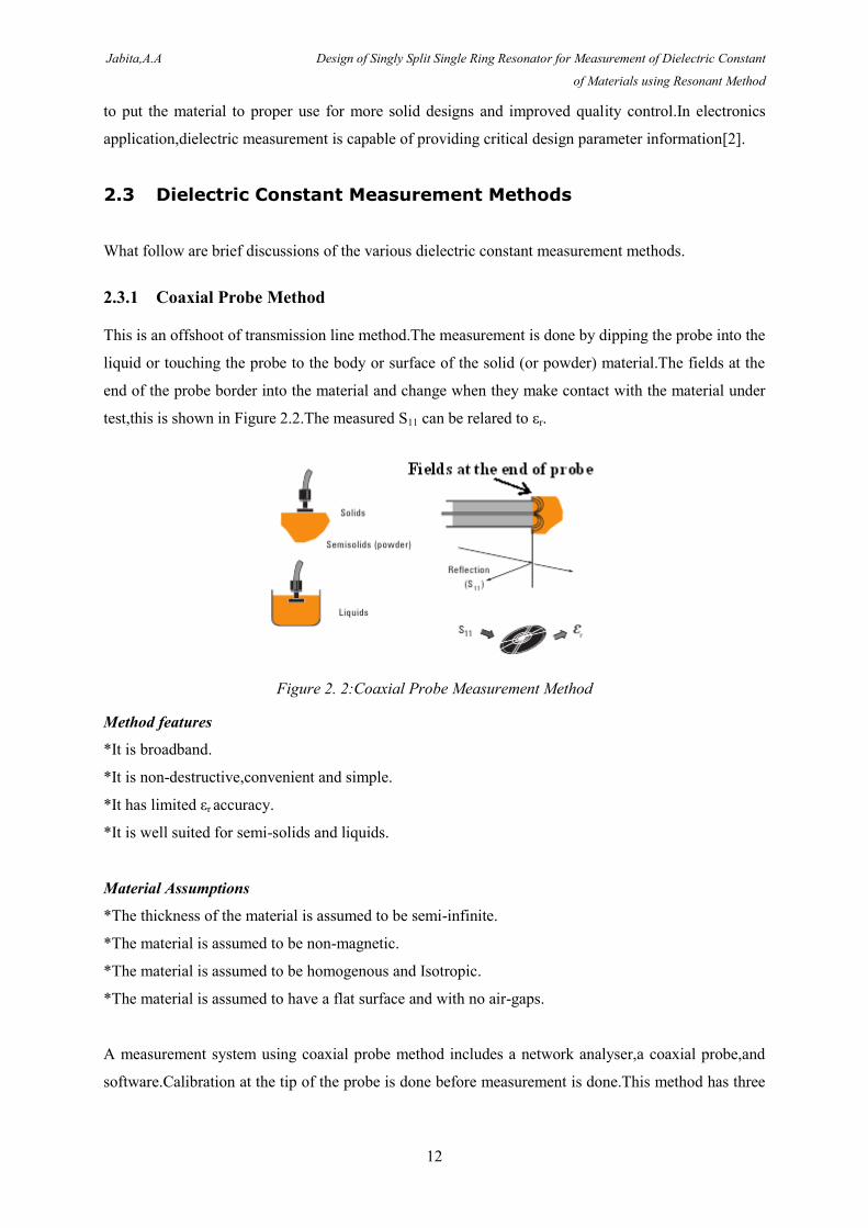
2.3.1 Coaxial Probe Method
This is an offshoot of transmission line method.The measurement is done by dipping the probe into the
liquid or touching the probe to the body or surface of the solid (or powder) material.The fields at the
end of the probe border into the material and change when they make contact with the material under
test,this is shown in Figure 2.2.The measured S11 can be relared to εr.
Figure 2. 2:Coaxial Probe Measurement Method
Method features
*It is broadband.
*It is non-destructive,convenient and simple.
*It has limited εr accuracy.
*It is well suited for semi-solids and liquids.
Material Assumptions
*The thickness of the material is assumed to be semi-infinite.
*The material is assumed to be non-magnetic.
*The material is assumed to be homogenous and Isotropic.
*The material is assumed to have a flat surface and with no air-gaps.
A measurement system using coaxial probe method includes a network analyser,a coaxial probe,and
software.Calibration at the tip of the probe is done before measurement is done.This method has three
Jabita,A.A Design of Singly Split Single Ring Resonator for Measurement of Dielectric Constant
of Materials using Resonant Method
13
sources of error which are sample thickness,cable stability,and air gaps.Air gaps occurring between the
probe and the sample is found in solid materials under test while air bubbles at the tip of the probe
can be a source of air gap for liquid materials.To limit the error caused by cable,enough time needs to
be allowed for the cable to attain stability before measurement is made and also,a surety has to be
made that between calibration and measurement,the cable is not flexed.The dielectric probe method is
not as accurate as transmission line and resonant methods.
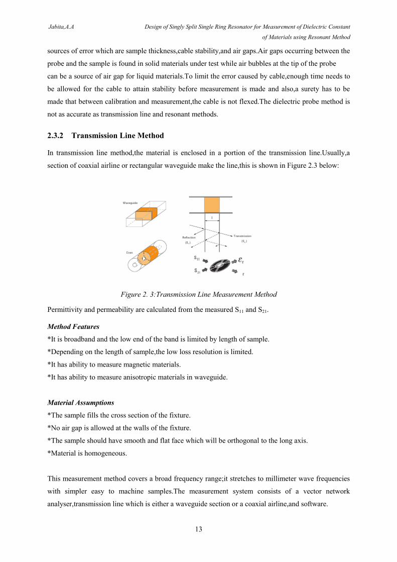
2.3.2 Transmission Line Method
In transmission line method,the material is enclosed in a portion of the transmission line.Usually,a
section of coaxial airline or rectangular waveguide make the line,this is shown in Figure 2.3 below:
Figure 2. 3:Transmission Line Measurement Method
Permittivity and permeability are calculated from the measured S11 and S21.
Method Features
*It is broadband and the low end of the band is limited by length of sample.
*Depending on the length of sample,the low loss resolution is limited.
*It has ability to measure magnetic materials.
*It has ability to measure anisotropic materials in waveguide.
Material Assumptions
*The sample fills the cross section of the fixture.
*No air gap is allowed at the walls of the fixture.
*The sample should have smooth and flat face which will be orthogonal to the long axis.
*Material is homogeneous.
This measurement method covers a broad frequency range;it stretches to millimeter wave frequencies
with simpler easy to machine samples.The measurement system consists of a vector network
analyser,transmission line which is either a waveguide section or a coaxial airline,and software.
Jabita,A.A Design of Singly Split Single Ring Resonator for Measurement of Dielectric Constant
of Materials using Resonant Method
14
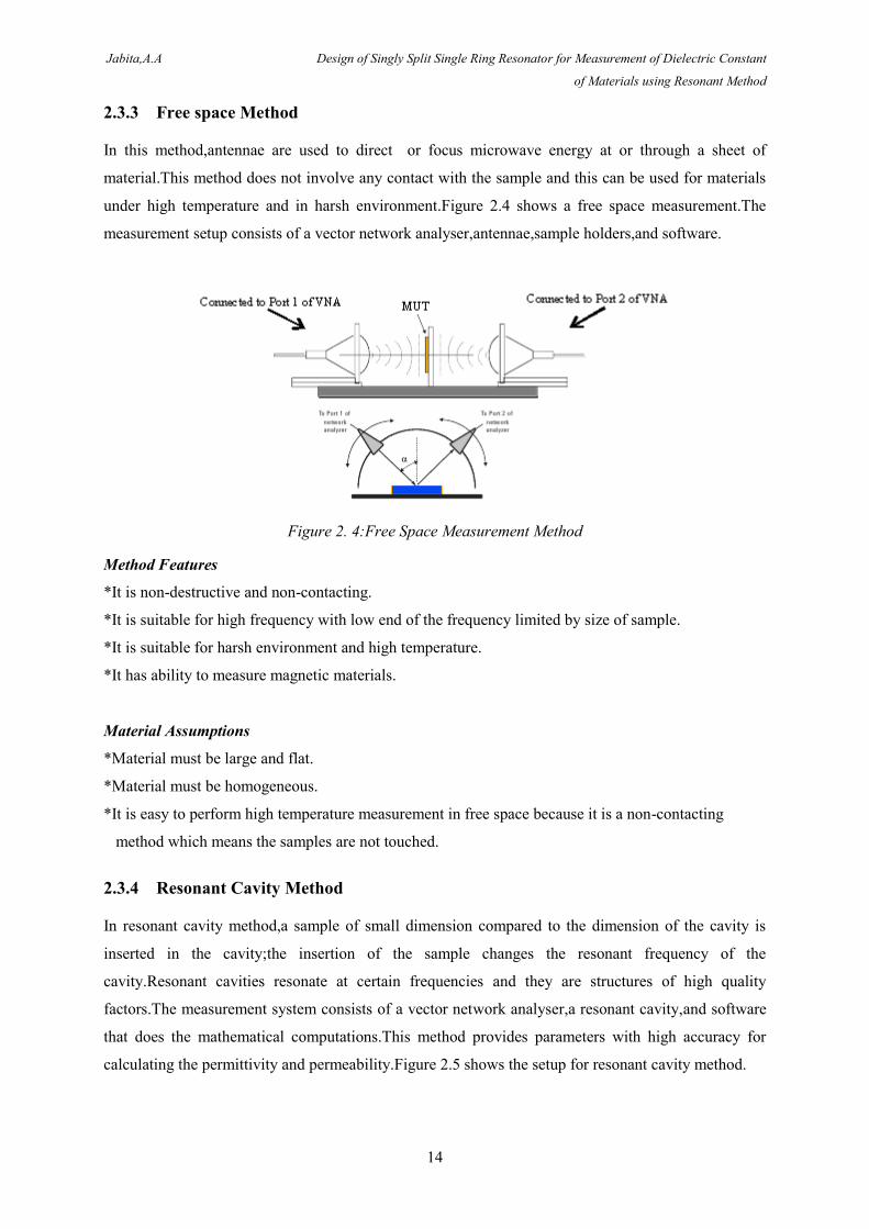
2.3.3 Free space Method
In this method,antennae are used to direct or focus microwave energy at or through a sheet of
material.This method does not involve any contact with the sample and this can be used for materials
under high temperature and in harsh environment.Figure 2.4 shows a free space measurement.The
measurement setup consists of a vector network analyser,antennae,sample holders,and software.
Figure 2. 4:Free Space Measurement Method
Method Features
*It is non-destructive and non-contacting.
*It is suitable for high frequency with low end of the frequency limited by size of sample.
*It is suitable for harsh environment and high temperature.
*It has ability to measure magnetic materials.
Material Assumptions
*Material must be large and flat.
*Material must be homogeneous.
*It is easy to perform high temperature measurement in free space because it is a non-contacting
method which means the samples are not touched.
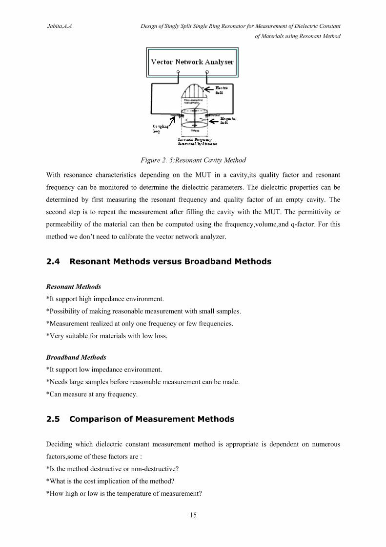
2.3.4 Resonant Cavity Method
In resonant cavity method,a sample of small dimension compared to the dimension of the cavity is
inserted in the cavity;the insertion of the sample changes the resonant frequency of the
cavity.Resonant cavities resonate at certain frequencies and they are structures of high quality
factors.The measurement system consists of a vector network analyser,a resonant cavity,and software
that does the mathematical computations.This method provides parameters with high accuracy for
calculating the permittivity and permeability.Figure 2.5 shows the setup for resonant cavity method.
Jabita,A.A Design of Singly Split Single Ring Resonator for Measurement of Dielectric Constant
of Materials using Resonant Method
15
Figure 2. 5:Resonant Cavity Method
With resonance characteristics depending on the MUT in a cavity,its quality factor and resonant
frequency can be monitored to determine the dielectric parameters. The dielectric properties can be
determined by first measuring the resonant frequency and quality factor of an empty cavity. The
second step is to repeat the measurement after filling the cavity with the MUT. The permittivity or
permeability of the material can then be computed using the frequency,volume,and q-factor. For this
method we don’t need to calibrate the vector network analyzer.
2.4 Resonant Methods versus Broadband Methods
Resonant Methods
*It support high impedance environment.
*Possibility of making reasonable measurement with small samples.
*Measurement realized at only one frequency or few frequencies.
*Very suitable for materials with low loss.
Broadband Methods
*It support low impedance environment.
*Needs large samples before reasonable measurement can be made.
*Can measure at any frequency.
2.5 Comparison of Measurement Methods
Deciding which dielectric constant measurement method is appropriate is dependent on numerous
factors,some of these factors are :
*Is the method destructive or non-destructive?
*What is the cost implication of the method?
*How high or low is the temperature of measurement?
Jabita,A.A Design of Singly Split Single Ring Resonator for Measurement of Dielectric Constant
of Materials using Resonant Method
16
*Will there be a contact with the sample or not?
*What is the sample size?
*What form does the material take,liquid,solid,powder?
*What is the property of the material,homogeneous or not?
*What measurement accuracy is required?
*At what frequency range will the measurement be performed?
*What are the expected values of permittivity and permeability?
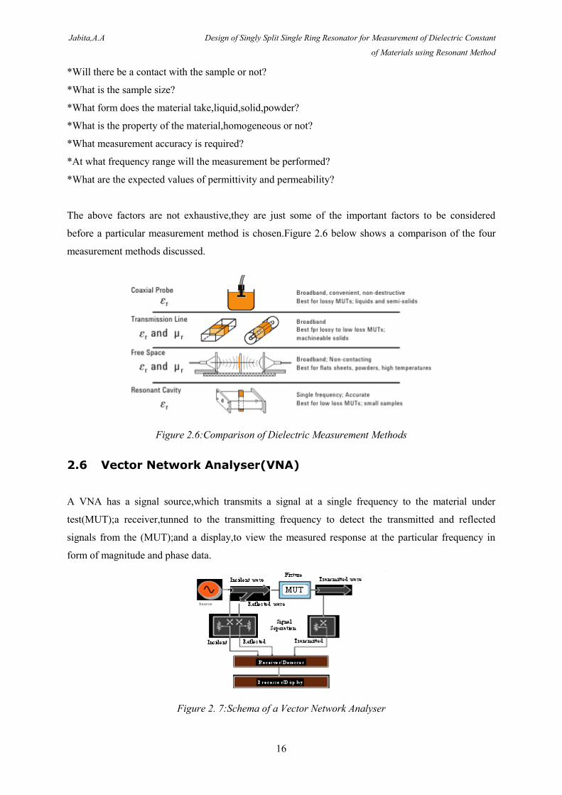
The above factors are not exhaustive,they are just some of the important factors to be considered
before a particular measurement method is chosen.Figure 2.6 below shows a comparison of the four
measurement methods discussed.
Figure 2.6:Comparison of Dielectric Measurement Methods
2.6 Vector Network Analyser(VNA)
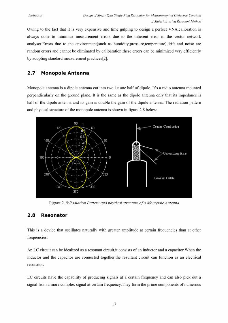
A VNA has a signal source,which transmits a signal at a single frequency to the material under
test(MUT);a receiver,tunned to the transmitting frequency to detect the transmitted and reflected
signals from the (MUT);and a display,to view the measured response at the particular frequency in
form of magnitude and phase data.
Figure 2. 7:Schema of a Vector Network Analyser
Jabita,A.A Design of Singly Split Single Ring Resonator for Measurement of Dielectric Constant
of Materials using Resonant Method
17
Owing to the fact that it is very expensive and time gulping to design a perfect VNA,calibration is
always done to minimize measurement errors due to the inherent error in the vector network
analyser.Errors due to the environment(such as humidity,pressure,temperature),drift and noise are
random errors and cannot be eliminated by calibaration;these errors can be minimized very efficiently
by adopting standard measurement practices[2].
2.7 Monopole Antenna
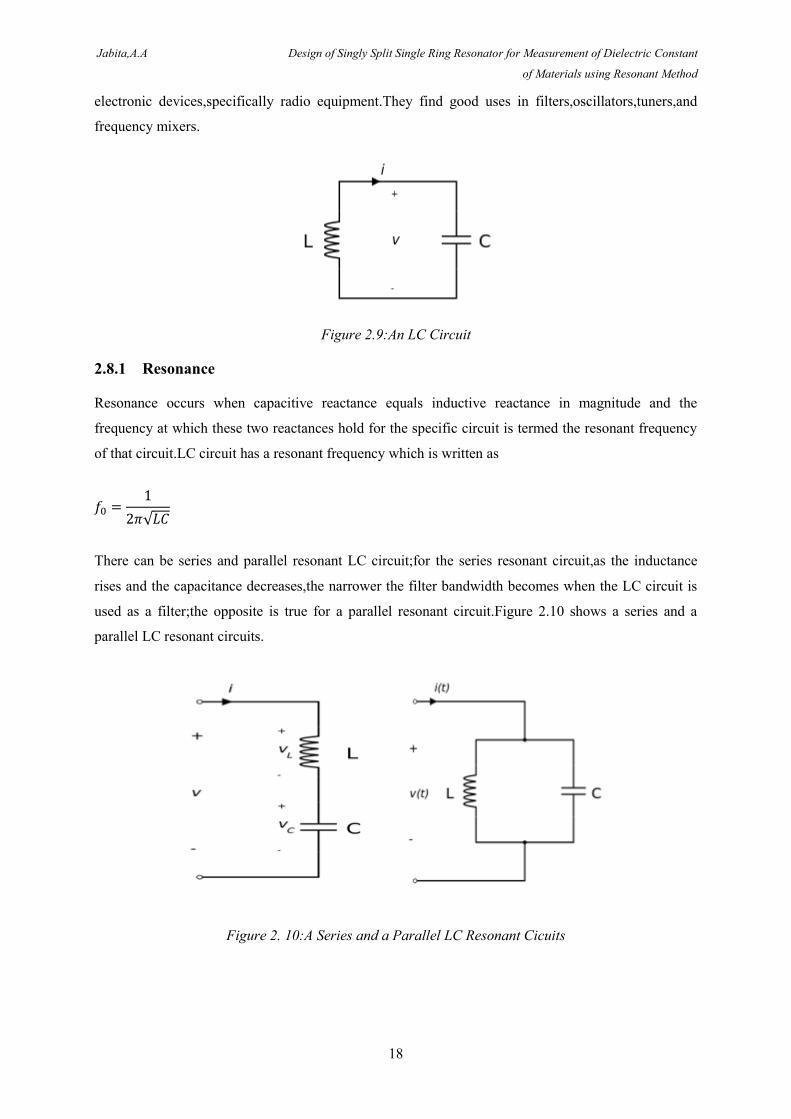
Monopole antenna is a dipole antenna cut into two i.e one half of dipole. It’s a radio antenna mounted
perpendicularly on the ground plane. It is the same as the dipole antenna only that its impedance is
half of the dipole antenna and its gain is double the gain of the dipole antenna. The radiation pattern
and physical structure of the monopole antenna is shown in figure 2.8 below:
Figure 2. 8:Radiation Pattern and physical structure of a Monopole Antenna
2.8 Resonator
This is a device that oscillates naturally with greater amplitude at certain frequencies than at other
frequencies.
An LC circuit can be idealized as a resonant circuit,it consists of an inductor and a capacitor.When the
inductor and the capacitor are connected together,the resultant circuit can function as an electrical
resonator.
LC circuits have the capability of producing signals at a certain frequency and can also pick out a
signal from a more complex signal at certain frequency.They form the prime components of numerous
Jabita,A.A Design of Singly Split Single Ring Resonator for Measurement of Dielectric Constant
of Materials using Resonant Method
18
electronic devices,specifically radio equipment.They find good uses in filters,oscillators,tuners,and
frequency mixers.
Figure 2.9:An LC Circuit
2.8.1 Resonance
Resonance occurs when capacitive reactance equals inductive reactance in magnitude and the
frequency at which these two reactances hold for the specific circuit is termed the resonant frequency
of that circuit.LC circuit has a resonant frequency which is written as
√
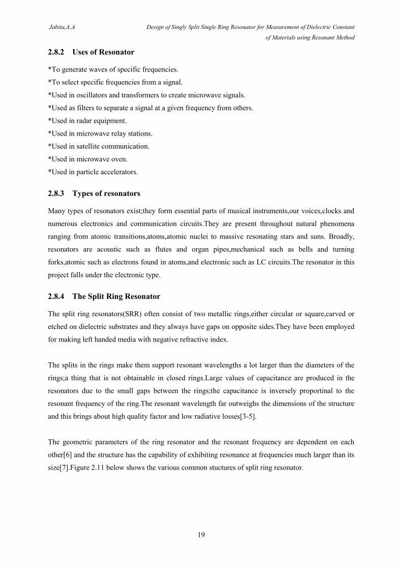
There can be series and parallel resonant LC circuit;for the series resonant circuit,as the inductance
rises and the capacitance decreases,the narrower the filter bandwidth becomes when the LC circuit is
used as a filter;the opposite is true for a parallel resonant circuit.Figure 2.10 shows a series and a
parallel LC resonant circuits.
Figure 2. 10:A Series and a Parallel LC Resonant Cicuits
Jabita,A.A Design of Singly Split Single Ring Resonator for Measurement of Dielectric Constant
of Materials using Resonant Method
19
2.8.2 Uses of Resonator
*To generate waves of specific frequencies.
*To select specific frequencies from a signal.
*Used in oscillators and transformers to create microwave signals.
*Used as filters to separate a signal at a given frequency from others.
*Used in radar equipment.
*Used in microwave relay stations.
*Used in satellite communication.
*Used in microwave oven.
*Used in particle accelerators.
2.8.3 Types of resonators
Many types of resonators exist;they form essential parts of musical instruments,our voices,clocks and
numerous electronics and communication circuits.They are present throughout natural phenomena
ranging from atomic transitions,atoms,atomic nuclei to massive resonating stars and suns. Broadly,
resonators are acoustic such as flutes and organ pipes,mechanical such as bells and turning
forks,atomic such as electrons found in atoms,and electronic such as LC circuits.The resonator in this
project falls under the electronic type.
2.8.4 The Split Ring Resonator
The split ring resonators(SRR) often consist of two metallic rings,either circular or square,carved or
etched on dielectric substrates and they always have gaps on opposite sides.They have been employed
for making left handed media with negative refractive index.
The splits in the rings make them support resonant wavelengths a lot larger than the diameters of the
rings;a thing that is not obtainable in closed rings.Large values of capacitance are produced in the
resonators due to the small gaps between the rings;the capacitance is inversely proportinal to the
resonant frequency of the ring.The resonant wavelength far outweighs the dimensions of the structure
and this brings about high quality factor and low radiative losses[3-5].
The geometric parameters of the ring resonator and the resonant frequency are dependent on each
other[6] and the structure has the capability of exhibiting resonance at frequencies much larger than its
size[7].Figure 2.11 below shows the various common stuctures of split ring resonator.
Jabita,A.A Design of Singly Split Single Ring Resonator for Measurement of Dielectric Constant
of Materials using Resonant Method
20
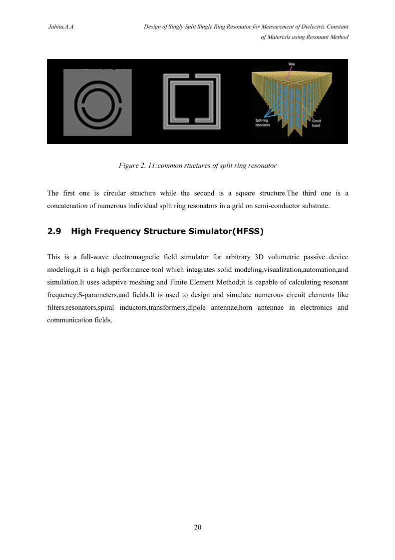
Figure 2. 11:common stuctures of split ring resonator
The first one is circular structure while the second is a square structure.The third one is a
concatenation of numerous individual split ring resonators in a grid on semi-conductor substrate.
2.9 High Frequency Structure Simulator(HFSS)
This is a full-wave electromagnetic field simulator for arbitrary 3D volumetric passive device
modeling,it is a high performance tool which integrates solid modeling,visualization,automation,and
simulation.It uses adaptive meshing and Finite Element Method;it is capable of calculating resonant
frequency,S-parameters,and fields.It is used to design and simulate numerous circuit elements like
filters,resonators,spiral inductors,transformers,dipole antennae,horn antennae in electronics and
communication fields.
Jabita,A.A Design of Singly Split Single Ring Resonator for Measurement of Dielectric Constant
of Materials using Resonant Method
21
3 Process and results
In this chapter,the understanding of the knowledge base in Chapter 2 was applied.Shift in resonant
frequency was used to measure the dielectric constant of any solid material of interest.This was
achieved by first measuring the resonant frequency of the ring without the MUT (Material Under
Test);second,the MUT was put in the gap of the ring and the resonant frequency was re-measured,this
time,the resonant frequency changed to a lesser one.Third,the new resonant frequency with the
geometric parameters of the ring and MUT were combined to derive equation (3.22) which was used
to calculate the dielectric constant.S21 was used to characterize the resonant frequencies.The chapter is
divided into three sections,Analysis of SRR,Simulation of SRR,and Measurement with SRR.
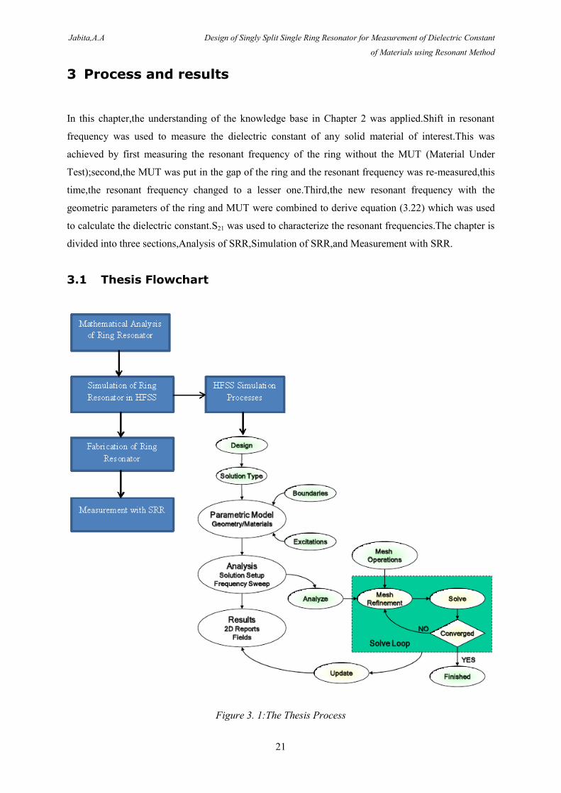
3.1 Thesis Flowchart
Figure 3. 1:The Thesis Process
Jabita,A.A Design of Singly Split Single Ring Resonator for Measurement of Dielectric Constant
of Materials using Resonant Method
22
Figure 3.1 above shows the various processes that were followed to achieve the aim of this thesis.
3.2 Analysis of SRR
The split ring is a basic geometry for the design of sub-wavelength magnetic meta-material resonators.
At microwave frequencies,double split rings design have gained so much popularity.From intuition,
analytical expressions for resonant frequencies of double ring constitution were derived while the
ones with more rigor were confirmed by experiment.The resonant properties of single rings have
gathered little study,analytically.Here,an analytical expression for the resonant frequency of the singly
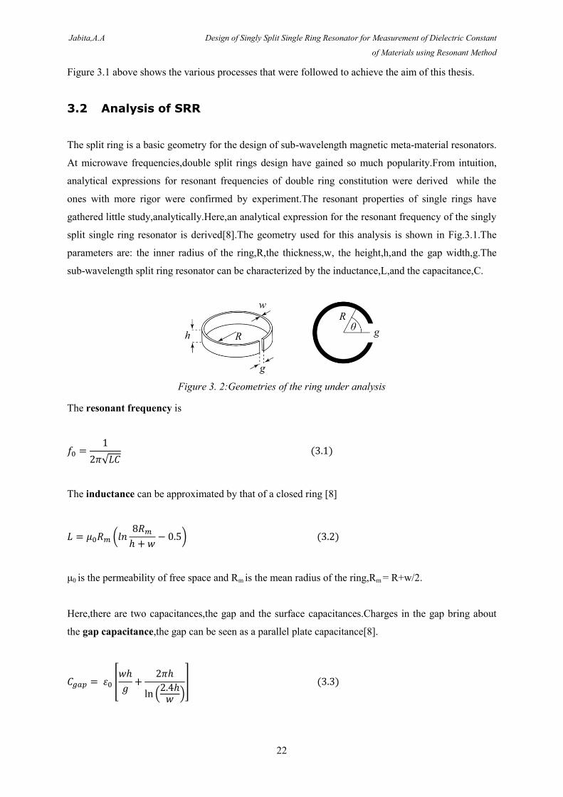
split single ring resonator is derived[8].The geometry used for this analysis is shown in Fig.3.1.The
parameters are: the inner radius of the ring,R,the thickness,w, the height,h,and the gap width,g.The
sub-wavelength split ring resonator can be characterized by the inductance,L,and the capacitance,C.
Figure 3. 2:Geometries of the ring under analysis
The resonant frequency is
√
The inductance can be approximated by that of a closed ring [8]
(
)
μ0 is the permeability of free space and Rm is the mean radius of the ring,Rm = R+w/2.
Here,there are two capacitances,the gap and the surface capacitances.Charges in the gap bring about
the gap capacitance,the gap can be seen as a parallel plate capacitance[8].
[
( )
]
Jabita,A.A Design of Singly Split Single Ring Resonator for Measurement of Dielectric Constant
of Materials using Resonant Method
23
The second term in equation (3.3) is a correction due to finite size[8] .
The surface capacitance is contributed by charges on the surface of the ring;the results obtained by
Allen and Segre [8-9] for infinitely long split cylinders with infinitesimal gap is used.For ζ,the surface
charge density, and the voltage V,we have
V0 is the applied voltage to the gap and the θ is the angle defined in Figure 3.2 above.With the
aforementioned,the surface capacitance is given by
∫
∫ (
)
Where θg = arcsin(g/2R).
With the assumption that the gap and surface capacitances are parallel,the total capacitance is given as
The ring resonator could be idealized as a parallel plate capacitor whose capacitance is written as
By extending this formula to the case of this project,the capacitance of the parallel plate capacitor is
likened to the capacitor in the gap of the ring resonator and is given as in equation (3.3).Putting
material in the gap splits this capacitance into two which are and .The is the cpacitance
due to the MUT and the is the capacitance due to the air left uncovered by the material.The two
capacitances are in series and their relation is given in equation (3.8) below:
From equation (3.3),we know that
Jabita,A.A Design of Singly Split Single Ring Resonator for Measurement of Dielectric Constant
of Materials using Resonant Method
24
[
( )
]
And deriving from here,we have
[
]
[
]
[
]
From equation (3.6), this means that
[
[
]
[
]
]
where
Equation (3.12) is the total capacitance when material is inserted in the gap.
From equation (3.1),
√
Jabita,A.A Design of Singly Split Single Ring Resonator for Measurement of Dielectric Constant
of Materials using Resonant Method
25
Customizing this equation to the case of an MUT in the gap,this resonant frequency changes to the one
below:
√ ( )
( )
( )
[
]
[
]
Equation (3.13) can be used to predict the new resonant frequency when the MUT is inserted in the
gap provided the dielectric consatnt of the MUT is known.Equation (3.22) is what was used for the
dielctric constant extraction after the shift in resonant frquencies were obtained.The MATLAB scripts
for these equations and the accompanying ones are found in the Appendix.
Jabita,A.A Design of Singly Split Single Ring Resonator for Measurement of Dielectric Constant
of Materials using Resonant Method
26
3.3 Simulation of SRR
Based on the foregoing mathematical analysis,a practicable ring resonator was designed;it could hold
the MUT(material under test),whose dielectric constant is to be measured,in its gap.The values of the
geometric parameters of the ring were chosen such that the first resonant frequency of the ring fell
within the measurable frequency range (1-14GHZ) of the VNA available in the laboratory; the first
resonant frequency was calculated with the different parameters constituting the geometry of the ring
resonator.Putting the four parameters:height(h),width(w),radius(R),and gap(g) of the ring resonator in
equation (3.1) repeatedly to get the resonant frequency and ensuring the fabrication practicability of
the ring is a gritty task without a programme that could iterate this process;thus,a MATLAB script was
written to address this issue.This script allows for iteration to be done with all the geometric
parameters in many times over so that a practicable ring of the designer’s choice could be realized;it
further gave the resonant frequency of any geometry of the ring.The script is in the Appendix.
After getting a ring resonator whose geometry was practicable,the ring and the measurement
environments were simulated with Ansys HFSS 13.0.The material for the ring resonator was stainless
steel and its geometry is given below:
Height(h) = 5mm
Width(w) = 2mm
Gap(g) = 6mm
Internal radius (R) = 13mm
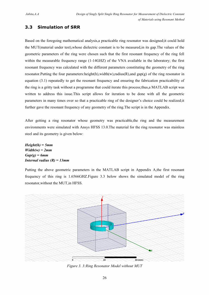
Putting the above geometric parameters in the MATLAB script in Appendix A,the first resonant
frequency of this ring is 1.6566GHZ.Figure 3.3 below shows the simulated model of the ring
resonator,without the MUT,in HFSS.
Figure 3. 3:Ring Resonator Model without MUT
Jabita,A.A Design of Singly Split Single Ring Resonator for Measurement of Dielectric Constant
of Materials using Resonant Method
27
The ring was enclosed in an air box because in HFSS,the background is a PEC (Perfect Electric
Conductor) and since the resonator was not to be put in a PEC during measurement,the air box had to
sorround the structure so that the transmission and reception of the EM (Electromagnetic Waves)
could occur in free space.The dimension of the airbox is at least λ/4 of the lowest resonant frequency.
3.3.1 Excitation and Boundaries in HFSS
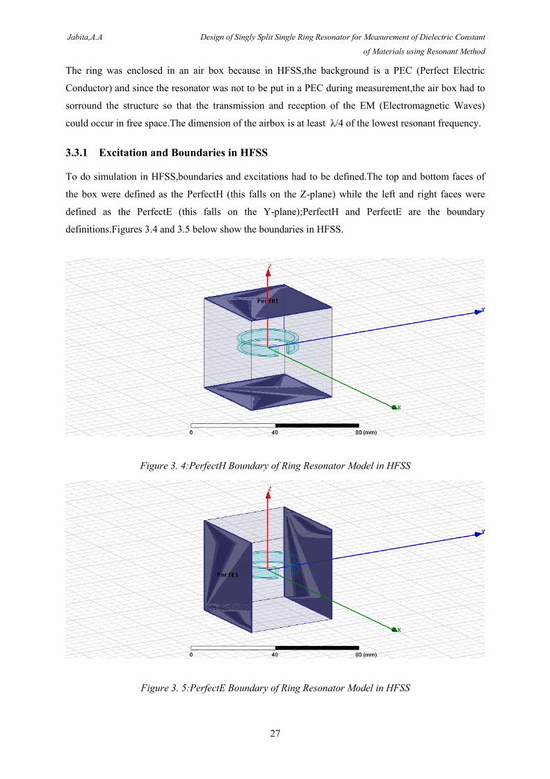
To do simulation in HFSS,boundaries and excitations had to be defined.The top and bottom faces of
the box were defined as the PerfectH (this falls on the Z-plane) while the left and right faces were
defined as the PerfectE (this falls on the Y-plane);PerfectH and PerfectE are the boundary
definitions.Figures 3.4 and 3.5 below show the boundaries in HFSS.
Figure 3. 4:PerfectH Boundary of Ring Resonator Model in HFSS
Figure 3. 5:PerfectE Boundary of Ring Resonator Model in HFSS
Jabita,A.A Design of Singly Split Single Ring Resonator for Measurement of Dielectric Constant
of Materials using Resonant Method
28
The PerfectH and PerfectE are orthogonal to each other due to the principle of electromagnetic
waves;PerfectH means perfect magnetic field while PerfectE means perfect electric field.
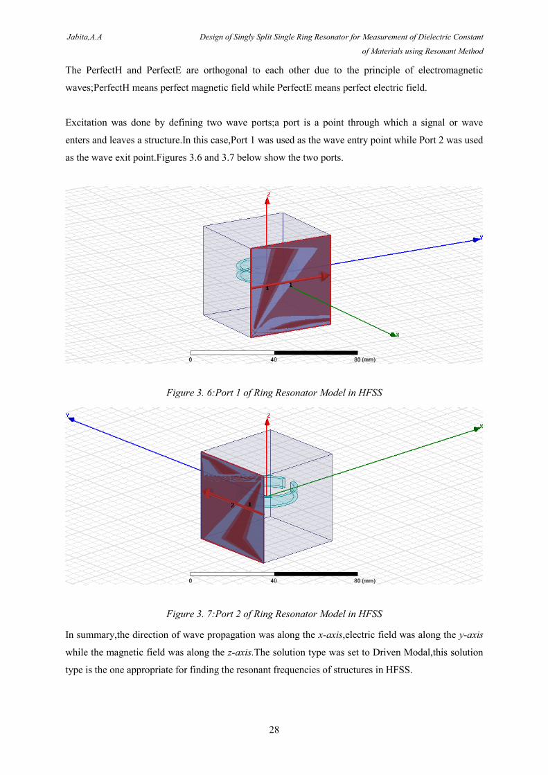
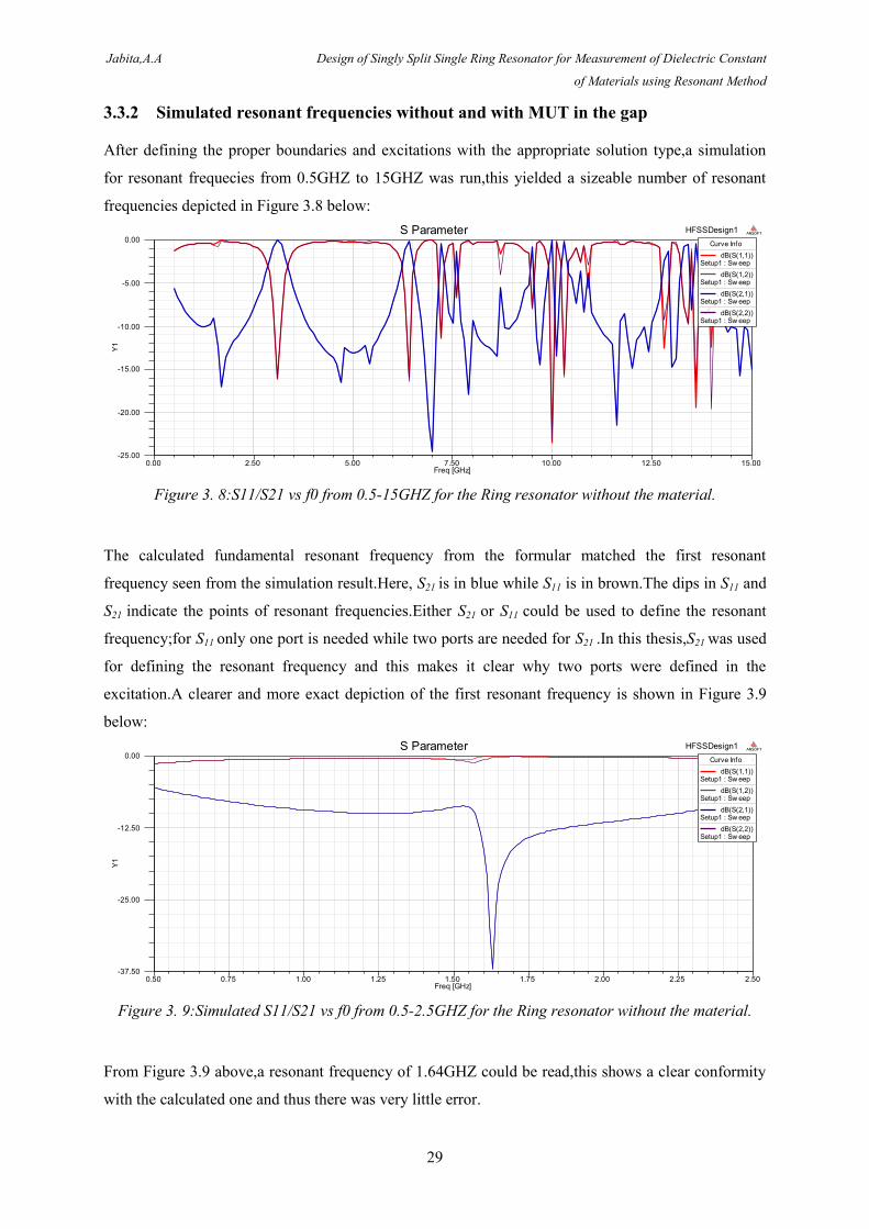
Excitation was done by defining two wave ports;a port is a point through which a signal or wave
enters and leaves a structure.In this case,Port 1 was used as the wave entry point while Port 2 was used
as the wave exit point.Figures 3.6 and 3.7 below show the two ports.
Figure 3. 6:Port 1 of Ring Resonator Model in HFSS
Figure 3. 7:Port 2 of Ring Resonator Model in HFSS
In summary,the direction of wave propagation was along the x-axis,electric field was along the y-axis
while the magnetic field was along the z-axis.The solution type was set to Driven Modal,this solution
type is the one appropriate for finding the resonant frequencies of structures in HFSS.
Jabita,A.A Design of Singly Split Single Ring Resonator for Measurement of Dielectric Constant
of Materials using Resonant Method
29
3.3.2 Simulated resonant frequencies without and with MUT in the gap
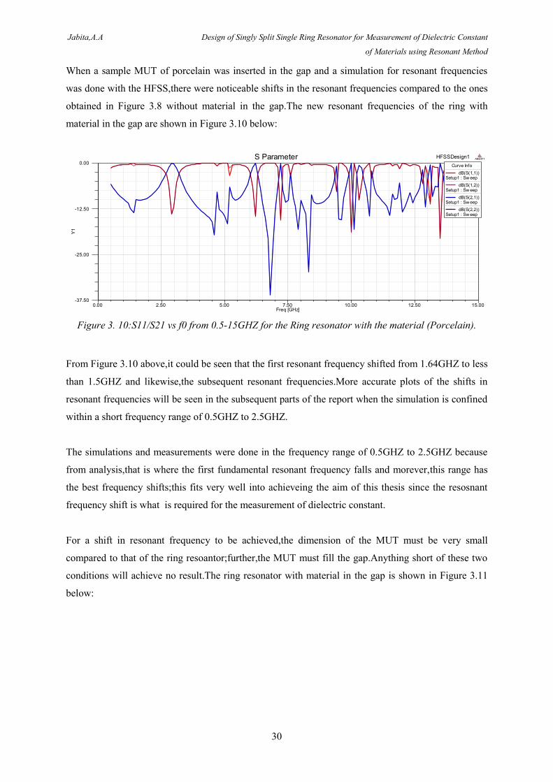
After defining the proper boundaries and excitations with the appropriate solution type,a simulation
for resonant frequecies from 0.5GHZ to 15GHZ was run,this yielded a sizeable number of resonant
frequencies depicted in Figure 3.8 below:
Figure 3. 8:S11/S21 vs f0 from 0.5-15GHZ for the Ring resonator without the material.
The calculated fundamental resonant frequency from the formular matched the first resonant
frequency seen from the simulation result.Here, S21 is in blue while S11 is in brown.The dips in S11 and
S21 indicate the points of resonant frequencies.Either S21 or S11 could be used to define the resonant
frequency;for S11 only one port is needed while two ports are needed for S21 .In this thesis,S21 was used
for defining the resonant frequency and this makes it clear why two ports were defined in the
excitation.A clearer and more exact depiction of the first resonant frequency is shown in Figure 3.9
below:
Figure 3. 9:Simulated S11/S21 vs f0 from 0.5-2.5GHZ for the Ring resonator without the material.
From Figure 3.9 above,a resonant frequency of 1.64GHZ could be read,this shows a clear conformity
with the calculated one and thus there was very little error.
0.00 2.50 5.00 7.50 10.00 12.50 15.00Freq [GHz]
-25.00
-20.00
-15.00
-10.00
-5.00
0.00
Y1
HFSSDesign1S Parameter ANSOFT
Curve Info
dB(S(1,1))Setup1 : Sw eep
dB(S(1,2))Setup1 : Sw eep
dB(S(2,1))Setup1 : Sw eep
dB(S(2,2))Setup1 : Sw eep
0.50 0.75 1.00 1.25 1.50 1.75 2.00 2.25 2.50Freq [GHz]
-37.50
-25.00
-12.50
0.00
Y1
HFSSDesign1S Parameter ANSOFT
Curve Info
dB(S(1,1))Setup1 : Sw eep
dB(S(1,2))Setup1 : Sw eep
dB(S(2,1))Setup1 : Sw eep
dB(S(2,2))Setup1 : Sw eep
Jabita,A.A Design of Singly Split Single Ring Resonator for Measurement of Dielectric Constant
of Materials using Resonant Method
30
When a sample MUT of porcelain was inserted in the gap and a simulation for resonant frequencies
was done with the HFSS,there were noticeable shifts in the resonant frequencies compared to the ones
obtained in Figure 3.8 without material in the gap.The new resonant frequencies of the ring with
material in the gap are shown in Figure 3.10 below:
Figure 3. 10:S11/S21 vs f0 from 0.5-15GHZ for the Ring resonator with the material (Porcelain).
From Figure 3.10 above,it could be seen that the first resonant frequency shifted from 1.64GHZ to less
than 1.5GHZ and likewise,the subsequent resonant frequencies.More accurate plots of the shifts in
resonant frequencies will be seen in the subsequent parts of the report when the simulation is confined
within a short frequency range of 0.5GHZ to 2.5GHZ.
The simulations and measurements were done in the frequency range of 0.5GHZ to 2.5GHZ because
from analysis,that is where the first fundamental resonant frequency falls and morever,this range has
the best frequency shifts;this fits very well into achieveing the aim of this thesis since the resosnant
frequency shift is what is required for the measurement of dielectric constant.
For a shift in resonant frequency to be achieved,the dimension of the MUT must be very small
compared to that of the ring resoantor;further,the MUT must fill the gap.Anything short of these two
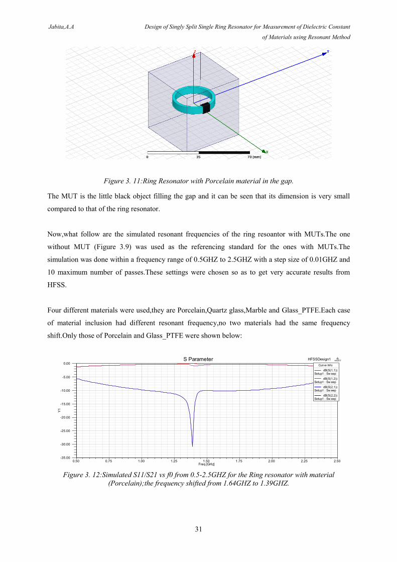
conditions will achieve no result.The ring resonator with material in the gap is shown in Figure 3.11
below:
0.00 2.50 5.00 7.50 10.00 12.50 15.00Freq [GHz]
-37.50
-25.00
-12.50
0.00
Y1
HFSSDesign1S Parameter ANSOFT
Curve Info
dB(S(1,1))Setup1 : Sw eep
dB(S(1,2))Setup1 : Sw eep
dB(S(2,1))Setup1 : Sw eep
dB(S(2,2))Setup1 : Sw eep
Jabita,A.A Design of Singly Split Single Ring Resonator for Measurement of Dielectric Constant
of Materials using Resonant Method
31
Figure 3. 11:Ring Resonator with Porcelain material in the gap.
The MUT is the little black object filling the gap and it can be seen that its dimension is very small
compared to that of the ring resonator.
Now,what follow are the simulated resonant frequencies of the ring resoantor with MUTs.The one
without MUT (Figure 3.9) was used as the referencing standard for the ones with MUTs.The
simulation was done within a frequency range of 0.5GHZ to 2.5GHZ with a step size of 0.01GHZ and
10 maximum number of passes.These settings were chosen so as to get very accurate results from
HFSS.
Four different materials were used,they are Porcelain,Quartz glass,Marble and Glass_PTFE.Each case
of material inclusion had different resonant frequency,no two materials had the same frequency
shift.Only those of Porcelain and Glass_PTFE were shown below:
Figure 3. 12:Simulated S11/S21 vs f0 from 0.5-2.5GHZ for the Ring resonator with material
(Porcelain);the frequency shifted from 1.64GHZ to 1.39GHZ.
0.50 0.75 1.00 1.25 1.50 1.75 2.00 2.25 2.50Freq [GHz]
-35.00
-30.00
-25.00
-20.00
-15.00
-10.00
-5.00
0.00
Y1
HFSSDesign1S Parameter ANSOFT
Curve Info
dB(S(1,1))Setup1 : Sw eep
dB(S(1,2))Setup1 : Sw eep
dB(S(2,1))Setup1 : Sw eep
dB(S(2,2))Setup1 : Sw eep
Jabita,A.A Design of Singly Split Single Ring Resonator for Measurement of Dielectric Constant
of Materials using Resonant Method
32
Figure 3. 13:Simulated S11/S21 vs f0 from 0.5-2.5GHZ for the Ring resonator with material
(Glass_PTFE);the frequency shifted from 1.64GHZ to 1.57GHZ.
In Figure 3.12,it could be seen that the resonant frequency shifted from 1.64GHZ to 1.39GHZ when
Porcelain was inserted in the gap while there was a shift of frequency from 1.64GHZ to 1.57GHZ
when Glass_PTFE was inserted in the gap.These shifts go inline with the prediction that putting
material in the gap increases the capacitance and since the resonant frequency and capacitance bear
inverse proportionality,the resonant frequency must certainly become lower than the one obtained
without material in the gap.
Further,plots of current distributions in the ring at each resonant frequecy from 1.64GHZ up to
10.2GHZ were made;these plots showed places of lowest and highest current in the structure at each
resonant frequency.The figures that follow show two of those current distributions plots.
Figure 3. 14:Current Distribution at Resonant Frequency of 1.64GHZ
0.50 0.75 1.00 1.25 1.50 1.75 2.00 2.25 2.50Freq [GHz]
-40.00
-35.00
-30.00
-25.00
-20.00
-15.00
-10.00
-5.00
0.00
Y1
HFSSDesign1S Parameter ANSOFT
Curve Info
dB(S(1,1))Setup1 : Sw eep
dB(S(1,2))Setup1 : Sw eep
dB(S(2,1))Setup1 : Sw eep
dB(S(2,2))Setup1 : Sw eep
Jabita,A.A Design of Singly Split Single Ring Resonator for Measurement of Dielectric Constant
of Materials using Resonant Method
33
Figure 3. 15:Current Distribution at Resonant Frequency of 4.7GHZ
Comparison between the two figures above shows that there are higher current distributions on the
ring at a resonant frequency of 1.64GHZ than when the ring is viewed at a resonant frequency of
4.7GHZ.
3.4 Measurement with SRR
After simulating for resonant frequencies without material and with different materials,the project
needed to be executed in the laboratory.It is the laboratory measurement that will tell whether the
designed and fabricated ring resonator will work or not.
Rhode & Schwarz ZVB 14 VNA operating at a frequency range of 10MHZ to 14GHZ with a pair of
monopole antennas were used.TOSM (Through-Open-Short-Match) full 2-port was used as the
calibration for the VNA;the VNA was calibrated for the entire operating frequency range.
The ring resonator was made of stainless steel;coaxial cables used for the monopole antennas were
designed to be λ/2 [10] of the measuring frequency range;the exposed centre conductors,which acted
as the transmitter and receiver,were 75mm long each,this conformed with λ/2.The distance between
the two monopole antennas was 45mm.The steps followed in the measurement are listed below:
1. One antenna was connected to port 1 of the VNA while the other was connected to port 2.The
one at port 1 was used as the transmitter while the one at port 2 was used as the receiver.
2. The ring resonator was placed between the antennae with equal distance from either of them.
Jabita,A.A Design of Singly Split Single Ring Resonator for Measurement of Dielectric Constant
of Materials using Resonant Method
34
3. The VNA was set to measure the resonant frequency of the ring resonator between 0.5GHZ
and 2.5GHZ without material in the gap and the resonant frequency was noted and recorded.
4. The VNA was set to measure the resonant frequency of the ring resonator between 0.5GHZ
and 2.5GHZ with material in the gap and the resonant frequency was noted and recorded.
After this step,a different material was put in the gap,the resonant frequency was also noted
and recorded.
The materials used were glass_PTFE and wood because these were the materials available in the
laboratory as at the time of making the measurement.The measured results without and with MUT in
the gap are given in the figures that follow.
Figure 3. 16:Measured S21 vs f0 from 1-2.5GHZ for the Ring resonator without the material,the
resonant frequency is at 1.65GHZ
Figure 3. 17:Measured S21 vs f0 from 1-2.5GHZ for the Ring resonator with the
material(Glass_PTFE),the resonant frequency shifted from 1.65GHZ to 1.59GHZ
Jabita,A.A Design of Singly Split Single Ring Resonator for Measurement of Dielectric Constant
of Materials using Resonant Method
35
Figure 3. 18:Measured S21 vs f0 from 1-2.5GHZ for the Ring resonator with the material(Wood),the
resonant frequency shifted from 1.65GHZ to 1.56GHZ
Comparison of results obtained in figure 3.16 to that of figure 3.9 showed a very good result and
conformity between the simulated result and measured result.The simulated result gave a resonant
frequency of 1.64GHZ without MUT in the gap while the measured result produced a resonant
frequency of 1.65GHZ without MUT.
Further,with the two different test materials put in the gap,the resonant frequency shifted for the
measurement as predicted in the aforementioned analysis and as obtained in the HFSS simulation with
different MUTs in the gap.
For Glass_PTFE insertion in the gap,the measured resonant frequency shifted from 1.65GHZ to
1.57GHZ while it shifted to 1.56GHZ for wood insertion into the gap.The obtained results showed
conformity amongst themselves as predicted by analysis,and as obtained from simulation and
measurement.
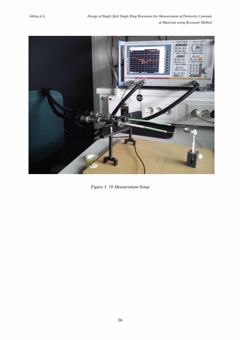
Below is a measurement setup,this shows how all the test materials were connected and arranged to
achieve the objective of the project.
The two green wires with silver cores are the monopole antennas assembly with one core functioning
as the transmitter and the other functioning as the receiver,the ring between them is the split ring
resonator.The black coaxial cables connect the monopole antennas assembly to the two ports of the
vector network analyser.
Jabita,A.A Design of Singly Split Single Ring Resonator for Measurement of Dielectric Constant
of Materials using Resonant Method
36
Figure 3. 19:Measurement Setup
Jabita,A.A Design of Singly Split Single Ring Resonator for Measurement of Dielectric Constant
of Materials using Resonant Method
37
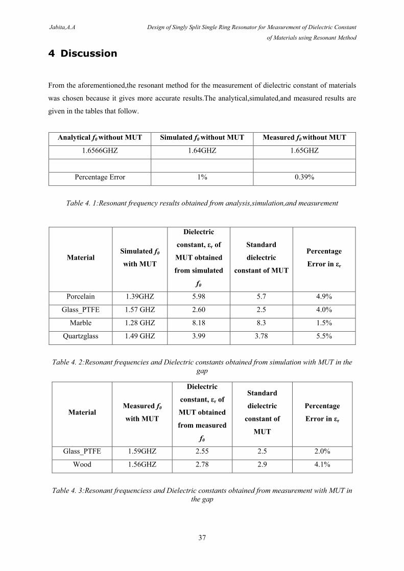
4 Discussion
From the aforementioned,the resonant method for the measurement of dielectric constant of materials
was chosen because it gives more accurate results.The analytical,simulated,and measured results are
given in the tables that follow.
Analytical f0 without MUT Simulated f0 without MUT Measured f0 without MUT
1.6566GHZ 1.64GHZ 1.65GHZ
Percentage Error 1% 0.39%
Table 4. 1:Resonant frequency results obtained from analysis,simulation,and measurement
Material Simulated f0
with MUT
Dielectric
constant, εr of
MUT obtained
from simulated
f0
Standard
dielectric
constant of MUT
Percentage
Error in εr
Porcelain 1.39GHZ 5.98 5.7 4.9%
Glass_PTFE 1.57 GHZ 2.60 2.5 4.0%
Marble 1.28 GHZ 8.18 8.3 1.5%
Quartzglass 1.49 GHZ 3.99 3.78 5.5%
Table 4. 2:Resonant frequencies and Dielectric constants obtained from simulation with MUT in the
gap
Material Measured f0
with MUT
Dielectric
constant, εr of
MUT obtained
from measured
f0
Standard
dielectric
constant of
MUT
Percentage
Error in εr
Glass_PTFE 1.59GHZ 2.55 2.5 2.0%
Wood 1.56GHZ 2.78 2.9 4.1%
Table 4. 3:Resonant frequenciess and Dielectric constants obtained from measurement with MUT in
the gap
Jabita,A.A Design of Singly Split Single Ring Resonator for Measurement of Dielectric Constant
of Materials using Resonant Method
38
The dielectric constants for each simulated and measured case was calculated with equation (3.22);the
equation accepts the inductance,surface capacitance,air capacitance,and the new resonant frequency
values when MUT is put in the gap as inputs.The script for the equation is in the Appendix .
From Tables 4.2 and 4.3,we could see that the errors in dielectric measurements are very minimal.The
possible sources of errors are:
1.The inherent errors in the measuring instruments as there are no 100% perfect such instruments.
2.Measurement error of the sample dimension.
3.Errors from the calibration of the VNA.
4.Errors from bends in the measuring cables.
5.Errors from exact positioning of the resonator between the two antennae.
6.Errors from the non-proper alignement of the edges of MUT with the two edges of the ring resonator
forming the gap.
On the whole, the results are good,the designed and fabricated resonator is reliable,and the project was
well executed.
Jabita,A.A Design of Singly Split Single Ring Resonator for Measurement of Dielectric Constant
of Materials using Resonant Method
39
5 Conclusions
Dielectric constants of different materials were successfully measured with the resonant method
employed in this thesis;it was done with a singly split single ring resonator.
Further work on this project will be in the form of concatenation of ten or more of this same single
ring resonator and the arrangement will be used for the measurement of dielectric constant of materials
as done in this project.
One major difference will be that two horn antennae will be used instead of monopole antennae used
herein.
I look forward to achieving good results as I did in this completed thesis.
Jabita,A.A Design of Singly Split Single Ring Resonator for Measurement of Dielectric Constant
of Materials using Resonant Method
40
References
[1] Rhode & Schwarz, "Measurement of Dielectric Material Properties",RAC-0607 0019_1_5E,
Application Notes, April 2012.
[2] Agilent Technologies, "Basics of Measuring the Dielectric Properties of Materials", 5989-2589EN
, Application Notes, April 2013.
[3] D.B. Juan, B. Jordi, M. Ferran, M.S. Ricard et al. "Equivalent-Circuit Models for Split-Ring
Resonators and Complementary Split-Ring Resonators Coupled to Planar Transmission Lines
", IEEE transactions on microwave theory and techniques, vol. 53, no. 4,pp.1451-1461,April 2005.
[4] G.B. Philippe and J. F. Olivier,"Electromagnetic resonances in individual and coupled split-ring
resonators ", Journal of applied physics, vol. 92,no. 5,pp.2929-2936,Sept. 2002.
[5] F. Medina ,R. Marques,J. Martel,and F. Mesa,"Left-Handed-Media Simulation and Transmission
of EM Waves in Subwavelength Split-Ring-Resonator-Loaded Metallic Waveguides", Physical
review letters,vol. 89, no. 18,pp.3901-3904,October 2002.
[6] E. Özbay ,and K. B. Alici,"Radiation properties of a split ring resonator and monopole composite
",phys. stat. sol. (b) 244, No. 4,1192–1196,2007.
[7] K. Aydin, K. Guven, M. Kafesaki, L. Zhang, C. M. Soukoulis,and E.Ozbay,"Experimental
observation of true left-handed transmission peak in metamaterials",Opt. Lett. 29,pp.2623-
2625,2004.
[8] O.Sydoruk,E. Tatartschuk1,E. Shamonina,and L. Solymar,"Resonant frequency of singly split
single ring resonators:an analytical and numerical study", presented at Metamaterials' 2008,2nd
International Congress on Advanced Electromagnetic Materials in Microwaves and
Optics,Pamplona,Spain,September 21-26,2008.
[9] J. E. Allen and S. E. Segre, "Electric field in single-turn and multi-sector coils", Nuov.Cim., vol.
21, pp.980-987,1961.
[10] K. Aydin and E. Ozbay,"Identifying magnetic response of split ring resonators at microwave
frequencies",Opto-Electronics Review 14,no 3,pp.193-199,2006.
Jabita,A.A Design of Singly Split Single Ring Resonator for Measurement of Dielectric Constant
of Materials using Resonant Method
A1
Appendix A
Resonant Frequency of Ring without MUT in the Gap
%Script file:resf
%Returns the resonant frequency of a Singly Split Single Ring Resonator
disp('****************************************************************************')
disp('This script Returns The Resonant Frequency of a Singly Split Single Ring Resonator');
disp('****************************************************************************')
R=input('*** Enter the Internal Radius of Ring in (mm):');
w=input('*** Enter the Width of Ring in (mm):');
g=input('*** Enter the Length of Gap in (mm):');
h=input('*** Enter the Height of Ring in (mm):');
Rm=R+w/2;
L=4*pi*10^-7*Rm*(log(8*Rm/(h+w))-0.5)*0.001;
C_gap=8.854*10^-12*((w*h/g)+(2*pi*h/log(2.4*h/w)))*0.001;
C_surf=(2*8.854*10^-12*h/pi)*log(4*R/g)*0.001;
C=C_gap+C_surf;
disp('***************************************************************************')
disp('The Resonant Frequency f_o in GHZ is :')
f_0=(1/(2*pi*sqrt(L*C)))*1e-9
disp('***************************************************************************')
Jabita,A.A Design of Singly Split Single Ring Resonator for Measurement of Dielectric Constant
of Materials using Resonant Method
A2
Resonant Frequency of Ring with MUT in the Gap
%Script file:nresf
%Returns the new resonant frequency of a Singly Split Single Ring Resonator
%with MUT in the Gap
disp('****************************************************************************')
disp('This script Returns The Resonant Frequency of a Singly Split Single Ring Resonator with MUT
in the Gap');
disp('****************************************************************************')
R=input('*** Enter the Internal Radius of Ring in (mm):');
w=input('*** Enter the Width of Ring in (mm):');
h=input('*** Enter the Height of Ring in (mm):');
g=input('*** Enter the Gap of Ring in (mm):');
E_r=input('*** Enter the Dielectric Constant of the MUT :');
Rm=R+w/2;
L=4*pi*10^-7*Rm*(log(8*Rm/(h+w))-0.5)*0.001;
C_mut=E_r*8.854*10^-12*((w*h/5.5)+(2*pi*h/log(2.4*h/w)))*0.001;
C_air=8.854*10^-12*((w*h/0.5)+(2*pi*h/log(2.4*h/w)))*0.001;
C_surf=(2*8.854*10^-12*h/pi)*log(4*R/g)*0.001;
C_gap=((1/C_mut)+(1/C_air))^-1;
C=C_gap+C_surf;
disp('****************************************************************************')
disp('The Resonant Frequency f_o in GHZ is :')
f_0new=(1/(2*pi*sqrt(L*C)))*1e-9
disp('****************************************************************************')
Jabita,A.A Design of Singly Split Single Ring Resonator for Measurement of Dielectric Constant
of Materials using Resonant Method
A3
Inductance of Ring Resonator
%Script file:inductance
%Returns the Inductance of a Singly Split Single Ring Resonator
disp('********************************************************')
disp('This script returns the inductance of a Singly Split Single Ring Resonator ');
disp('********************************************************')
R=input('*** Enter R in (mm):');
w=input('*** Enter w in (mm):');
h=input('*** Enter h in (mm):');
Rm=R+(w/2);
disp('*********************************************************')
disp('The inductance L in H is :')
L=4*pi*10^-7*Rm*(log(8*Rm/(h+w))-0.5)*0.001
disp('*********************************************************')
Gap Capacitance without MUT
%Script file:cgap
%Returns the Gap Capacitance of a Singly Split Single Ring Resonator without MUT
disp('****************************************************************)
disp('This script returns the gap capacitance of a Singly Split Single Ring Resonator ');
disp('****************************************************************')
w=input('*** Enter w in (mm):');
g=input('*** Enter g in (mm):');
h=input('*** Enter h in (mm):');
disp('****************************************************************')
disp('The gap capacitance in F is :')
C_gap=8.854*10^-12*((w*h/g)+(2*pi*h/log(2.4*h/w)))*0.001
disp('****************************************************************')
Jabita,A.A Design of Singly Split Single Ring Resonator for Measurement of Dielectric Constant
of Materials using Resonant Method
A4
Surface Capacitance
%Script file:csurf
%Returns the Surface Capacitance of a Singly Split Single Ring Resonator
disp('******************************************************************')
disp('This script returns the surface capacitance of a Singly Split Single Ring Resonator ');
disp('******************************************************************')
R=input('*** Enter R in (mm):');
g=input('*** Enter g in (mm):');
h=input('*** Enter h in (mm):');
disp('******************************************************************')
disp('The surface capacitance in F is :')
C_surf=(2*8.854*10^-12*h/pi)*log(4*R/g)*0.001
disp('******************************************************************')
Total Capacitance a Singly Split Single Ring Resonator without MUT
%Script file:ctot
%Returns the Total Capacitance of a Singly Split Single Ring Resonator
disp('*****************************************************************')
disp('This script returns the Total Capacitance of a Singly Split Single Ring Resonator ');
disp('*****************************************************************')
R=input('*** Enter R in (mm):');
w=input('*** Enter w in (mm):');
g=input('*** Enter g in (mm):');
h=input('*** Enter h in (mm):');
C_gap=8.854*10^-12*((w*h/g)+(2*pi*h/log(2.4*h/w)))*0.001;
C_surf=(2*8.854*10^-12*h/pi)*log(4*R/g)*0.001;
disp('****************************************************************')
disp('The total capacitance C in F is :')
C=C_gap+C_surf
disp('****************************************************************')
Jabita,A.A Design of Singly Split Single Ring Resonator for Measurement of Dielectric Constant
of Materials using Resonant Method
A5
Capacitance contributed by Air in a Singly Split Single Ring Resonator with MUT
%Script file:cair
%Returns the capacitance contributed by air in a Total Capacitance of a Singly Split Single Ring
Resonator
disp('**************************************************************************')
disp('This Script Returns the Capacitance contributed by Air in a Singly Split Single Ring Resonator
r');
disp('**************************************************************************')
w=input('*** Enter w in (mm):');
h=input('*** Enter h in (mm):');
disp('**************************************************************************')
disp('The capacitance in F is :')
C_air=8.854*10^-12*((w*h/0.5)+(2*pi*h/log(2.4*h/w)))*0.001
disp('**************************************************************************')
Capacitance contributed by Material in a Singly Split Single Ring Resonator with MUT
%Script file:cmut
%Returns the capacitance contributed by the MUT.
disp('************************************************************************')
disp('This script returns the Capacitance contributed by the MUT in a Singly Split Single Ring
Resonator’);
disp('************************************************************************')
w=input('*** Enter w,the Width of the Ring in (mm):');
h=input('*** Enter h,the Height of the Ring in (mm):');
E_r=input('*** Enter E_r,the Dielectric Constant of MUT:');
disp('************************************************************************')
disp('The capacitance in F is :')
C_mut=E_r*8.854*10^-12*((w*h/5.5)+(2*pi*h/log(2.4*h/w)))*0.001
disp('************************************************************************')
Jabita,A.A Design of Singly Split Single Ring Resonator for Measurement of Dielectric Constant
of Materials using Resonant Method
A6
The Resultant Gap Capacitance a Singly Split Single Ring Resonator with MUT
%Script file:cgap
%Returns the gap capacitance of a Singly Split Single Ring Resonator
disp('*****************************************************************************')
disp('This script returns the gap capacitance of a single split single ring resonator');
disp('*****************************************************************************')
w=input('*** Enter w,the width of the ring in (mm):');
h=input('*** Enter h,the height of the ring in (mm):');
E_r=input('*** Enter E_r,the dielectric constant of the MUT:');
C_mut=E_r*8.854*10^-12*((w*h/5.5)+(2*pi*h/log(2.4*h/w)))*0.001;
C_air=8.854*10^-12*((w*h/0.5)+(2*pi*h/log(2.4*h/w)))*0.001;
disp('*****************************************************************************')
disp('The Gap Capacitance,C_gap,in F is :')
C_gap=(1/C_mut+1/C_air)^-1
disp('*****************************************************************************')
The Dielectric Constant of the MUT in the Gap
%Script file:dielec
%Returns the The Dielectric Constant of the MUT in the Gap
disp('**********************************************************************')
disp('This script The Dielectric Constant of the MUT in the Gap');
disp('**********************************************************************')
R=input('*** Enter the Internal Radius of Ring in (mm):');
w=input('*** Enter the Width of Ring in (mm):');
h=input('*** Enter the Height of Ring in (mm):');
g=input('*** Enter the Gap of Ring in (mm):');
f_0new=input('*** Enter the new resonant frequency in HZ:');
Rm=R+w/2;
L=4*pi*10^-7*Rm*(log(8*Rm/(h+w))-0.5)*0.001;
C_air=8.854*10^-12*((w*h/0.5)+(2*pi*h/log(2.4*h/w)))*0.001;
C_surf=(2*8.854*10^-12*h/pi)*log(4*R/g)*0.001;
disp('***********************************************************************')
disp('The Dielectric Constant of the MUT is :')
E_r=((((2*pi*f_0new)^2*L)/(1-(2*pi*f_0new^2)*L*C_surf)-(1/C_air))*1.7134^-13)^-1*(1e9)
disp('***********************************************************************')
Jabita,A.A Design of Singly Split Single Ring Resonator for Measurement of Dielectric Constant
of Materials using Resonant Method
A7
New resonant frequency of a Singly Split Single Ring Resonator with MUT in the Gap
%Script file:nresf
%Returns the new resonant frequency of a Singly Split Single Ring Resonator
%with MUT in the Gap
disp('*****************************************************************************)
disp('This script Returns The Resonant Frequency of a Singly Split Single Ring Resonator with MUT
in the Gap');
disp('*****************************************************************************')
R=input('*** Enter the Internal Radius of Ring in (mm):');
w=input('*** Enter the Width of Ring in (mm):');
h=input('*** Enter the Height of Ring in (mm):');
g=input('*** Enter the Gap of Ring in (mm):');
E_r=input('*** Enter the Dielectric Constant of the MUT :');
Rm=R+w/2;
L=4*pi*10^-7*Rm*(log(8*Rm/(h+w))-0.5)*0.001;
C_mut=E_r*8.854*10^-12*((w*h/5.5)+(2*pi*h/log(2.4*h/w)))*0.001;
C_air=8.854*10^-12*((w*h/0.5)+(2*pi*h/log(2.4*h/w)))*0.001;
C_surf=(2*8.854*10^-12*h/pi)*log(4*R/g)*0.001;
C_gap=((1/C_mut)+(1/C_air))^-1;
C=C_gap+C_surf;
disp('*****************************************************************************')
disp('The Resonant Frequency f_o in GHZ is :')
f_0new=(1/(2*pi*sqrt(L*C)))*1e-9
disp('*****************************************************************************')
![Improved Split-Ring Resonator for Microfluidicorca.cf.ac.uk/59763/1/Improved split ring.pdf · 2020. 11. 26. · The resonant frequency of a cavity resonator [13] is set by its dimensions,](https://img.pdfslide.us/doc/110x75/60f99d8762b1d658425e30d9/improved-split-ring-resonator-for-split-ringpdf-2020-11-26-the-resonant.jpg)


![Symmetry breaking and strong coupling in planar optical ...double split-ring resonator (SRR) initially introduced by Pendry for operation at microwave frequencies [13]. Split-ring](https://img.pdfslide.us/doc/110x75/6048117d247d862a0e50c08f/symmetry-breaking-and-strong-coupling-in-planar-optical-double-split-ring-resonator.jpg)