Embed Size (px)
Citation preview
Planning Act 2008 The Infrastructure Planning (Applications: Prescribed Forms and Procedure) Regulations 2009
The Wrexham(Gas Fired Power Station) Order
Revision: Date: Description:
0 March 2016 Submission version
PINS Reference Number: EN010055Document Reference Number: 6.2.4Regulation Number: 5(2) (a)Lead Author: Savills (UK) Ltd.
6.2.4 Volume 2: Environmental Statement Chapter 4: The proposed development
SEC6-ES Vol1_A4 chapterTabs.indd 5 15/03/2016 10:49

WREXHAM ENERGY CENTRE ENVIRONMENTAL STATEMENT
4-1
Chapter 4 The proposed development
INTRODUCTION
4.1 As noted in chapter 1 of this Environmental Statement (ES), the Scheme includes a Combined Cycle Gas Turbine (CCGT) Power Station. To operate, it will require a connection to the gas transmission network for importing the natural gas fuel, and a connection to the electricity network to export the power generated.
4.2 The Power Station Complex Site constitutes a Nationally Significant Infrastructure Project ("NSIP") by virtue of section 14(1)(a) and section 15 of the Planning Act 2008 (PA 2008) which includes within the definition of an NSIP any onshore generating station in England or Wales of 50MWe capacity or more. Under section 31 PA 2008 a Development Consent Order ("DCO") is required to develop an NSIP. Under section 37 PA 2008 this can only be granted if an application is made for it to the relevant Secretary of State (SoS) (the "Application").
4.3 As detailed in chapter 1 of this ES, the Gas Connection element of the Scheme is being separately consented under the Town and County Planning Act 1990 via a planning application to the local planning authority. On the basis that powers of compulsory acquisition over the land required for the Gas Connection are being sought as part of the DCO application, the ES has considered and assessed both the Power Station Complex Site and the associated Gas Connection. In addition, the ES has cumulatively assessed other proposed developments including the Electrical Connection required for the WEC.
4.4 The Scheme comprises:
a combined cycle gas turbine (CCGT) power station (the "Power Station Complex") (work numbered 1 in Schedule 1 to the Order) which would be fuelled by natural gas and would have an electrical generation capacity of up to 299 megawatts (MWe);
the temporary and permanent Laydown Areas (works numbered 2A and 2B respectively in Schedule 1 to the Order);
surface water drainage works (work numbered 3 in Schedule 1 to the Order);
the landscaping and ecological mitigation works (work numbered 4 in Schedule 1 to the Order);
the alteration and use of the Kingmoor Park Access Road (work numbered 5 in Schedule 1 to the Order) (together the “Power Station Complex Site”);
WREXHAM ENERGY CENTRE ENVIRONMENTAL STATEMENT
4-2
the gas connection and an Above Ground Installation (AGI) (the "Gas Connection").
4.5 Paragraph 2.44 of the Scoping Opinion (May 2014) for the current EIA advised that:
"The applicant should ensure that the description of the proposed development that is being applied for is as accurate and firm as possible as this will form the basis of the environmental impact assessment. It is understood that at this stage in the evolution of the scheme the description of the proposals and even the location of the site may not be confirmed. The applicant should be aware however, that the description of the development in the ES must be sufficiently certain to meet the requirements of paragraph 17 of Schedule 4 Part 1 of the EIA Regulations and there should therefore be more certainty by the time the ES is submitted with the DCO. The project description must be accurate and consistent with what is being applied for in the DCO".
4.6 This chapter provides a description of the Site and surroundings and identifies the physical and operational parameters that have been used in the Environmental Impact Assessment (EIA) of the Scheme and how these have been arrived at.
4.7 Appendix 3 of the Scoping Opinion refers to the Rochdale Envelope, which applies where a degree of flexibility is required in the final design of a development at the point of consent. It stated that:
"The Rochdale Envelope principle (see R v Rochdale MBC ex parte Tew (1999) and R v Rochdale MBC ex parte Milne (2000)) is an accepted way of dealing with uncertainty in preparing development applications. The applicant’s attention is drawn to the Planning Inspectorate’s Advice Note 9 ‘Rochdale Envelope’ which is available on the Advice Notes page of the National Infrastructure Planning website.
The applicant should make every attempt to narrow the range of options and explain clearly in the Environmental Statement which elements of the scheme have yet to be finalised and provide the reasons. Where some flexibility is sought and the precise details are not known, the applicant should assess the maximum potential adverse impacts the project could have to ensure that the project as it may be constructed has been properly assessed.
The ES should be able to confirm that any changes to the development within any proposed parameters would not result in significant impacts not previously identified and assessed. The maximum and other dimensions of the proposed development should be clearly described in the ES, with appropriate justification. It will also be important to consider choice of materials, colour and the form of the structures and of any buildings".

WREXHAM ENERGY CENTRE ENVIRONMENTAL STATEMENT
4-3
4.8 The flexibility of the design at this stage is explained in paragraphs 4.68- 4.105 below, with the maximum dimensions and parameters of the Scheme specified in order to ensure that all relevant likely significant environmental impacts have been identified and assessed.
THE SITE AND SURROUNDINGS
4.9 The location of the WEC is shown in Figure 4.1 below. The proposed Power Station Complex Site is situated to the immediate north-east of Wrexham Industrial Estate in an area dominated by industrial complexes, to the west and south, and by agricultural land, to the north and east. The Gas Connection Route runs through agricultural land to the south and east of Wrexham Industrial Estate to the Above Ground Installation (AGI) adjacent to the Maelor Gas Works approximately 2.5 km to the south-west.
4.10 The Power Station Complex Site is situated to the east of Bryn Lane in the north-east part of the Wrexham Industrial Estate (WIE), on land allocated for major employment development by policy E3 of the Wrexham Unitary Development Plan. The WIE is one of the largest industrial estates in Wales.
Inset from Figure 4.1: Location Plan and Order Land
WREXHAM ENERGY CENTRE ENVIRONMENTAL STATEMENT
4-4
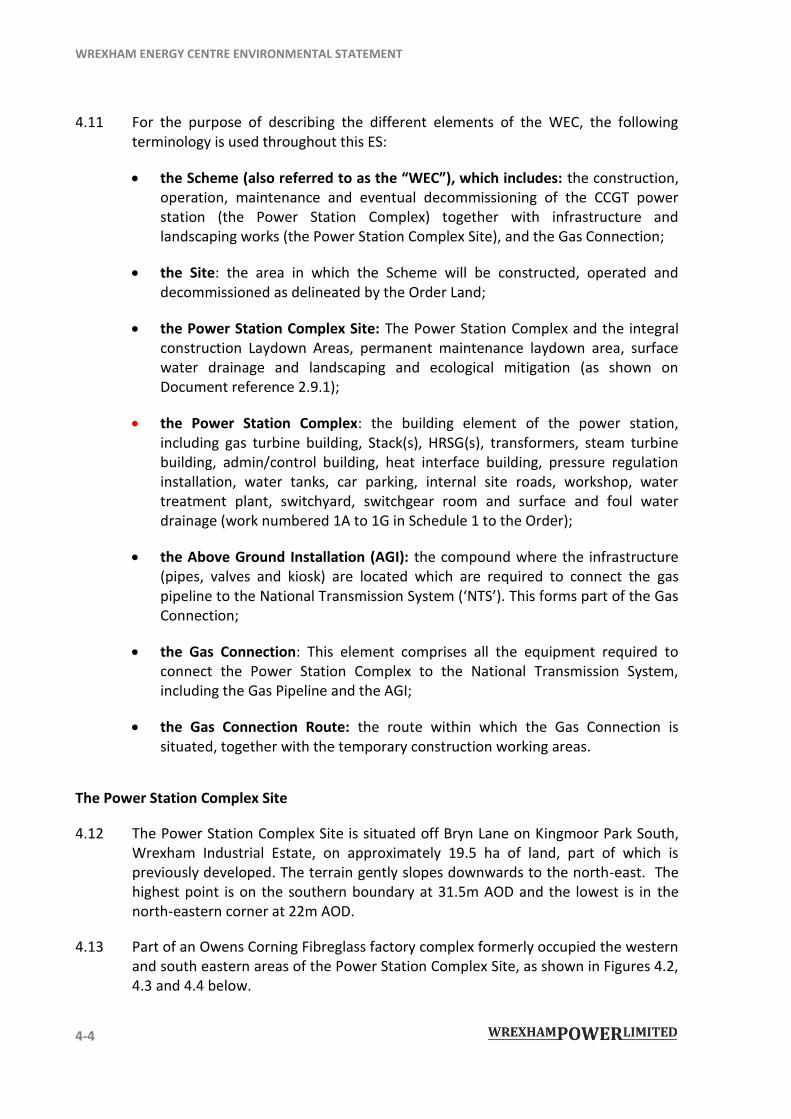
4.11 For the purpose of describing the different elements of the WEC, the following terminology is used throughout this ES:
the Scheme (also referred to as the “WEC”), which includes: the construction, operation, maintenance and eventual decommissioning of the CCGT power station (the Power Station Complex) together with infrastructure and landscaping works (the Power Station Complex Site), and the Gas Connection;
the Site: the area in which the Scheme will be constructed, operated and decommissioned as delineated by the Order Land;
the Power Station Complex Site: The Power Station Complex and the integral construction Laydown Areas, permanent maintenance laydown area, surface water drainage and landscaping and ecological mitigation (as shown on Document reference 2.9.1);
the Power Station Complex: the building element of the power station, including gas turbine building, Stack(s), HRSG(s), transformers, steam turbine building, admin/control building, heat interface building, pressure regulation installation, water tanks, car parking, internal site roads, workshop, water treatment plant, switchyard, switchgear room and surface and foul water drainage (work numbered 1A to 1G in Schedule 1 to the Order);
the Above Ground Installation (AGI): the compound where the infrastructure (pipes, valves and kiosk) are located which are required to connect the gas pipeline to the National Transmission System (‘NTS’). This forms part of the Gas Connection;
the Gas Connection: This element comprises all the equipment required to connect the Power Station Complex to the National Transmission System, including the Gas Pipeline and the AGI;
the Gas Connection Route: the route within which the Gas Connection is situated, together with the temporary construction working areas.
The Power Station Complex Site
4.12 The Power Station Complex Site is situated off Bryn Lane on Kingmoor Park South, Wrexham Industrial Estate, on approximately 19.5 ha of land, part of which is previously developed. The terrain gently slopes downwards to the north-east. The highest point is on the southern boundary at 31.5m AOD and the lowest is in the north-eastern corner at 22m AOD.
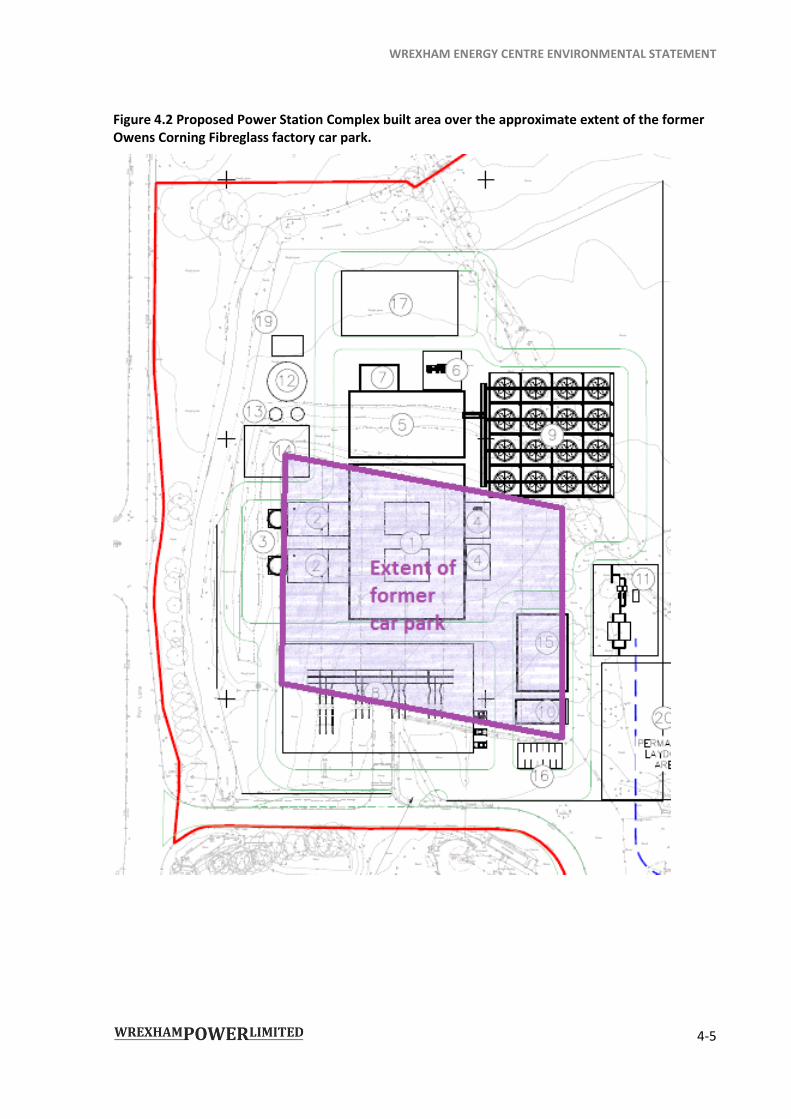
4.13 Part of an Owens Corning Fibreglass factory complex formerly occupied the western and south eastern areas of the Power Station Complex Site, as shown in Figures 4.2, 4.3 and 4.4 below.
WREXHAM ENERGY CENTRE ENVIRONMENTAL STATEMENT
4-5
Figure 4.2 Proposed Power Station Complex built area over the approximate extent of the former Owens Corning Fibreglass factory car park.
WREXHAM ENERGY CENTRE ENVIRONMENTAL STATEMENT
4-6
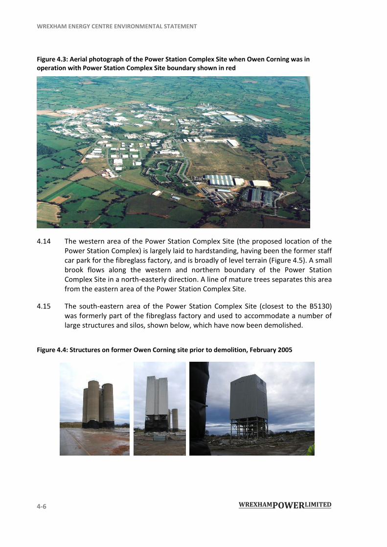
Figure 4.3: Aerial photograph of the Power Station Complex Site when Owen Corning was in operation with Power Station Complex Site boundary shown in red
4.14 The western area of the Power Station Complex Site (the proposed location of the Power Station Complex) is largely laid to hardstanding, having been the former staff car park for the fibreglass factory, and is broadly of level terrain (Figure 4.5). A small brook flows along the western and northern boundary of the Power Station Complex Site in a north-easterly direction. A line of mature trees separates this area from the eastern area of the Power Station Complex Site.
4.15 The south-eastern area of the Power Station Complex Site (closest to the B5130) was formerly part of the fibreglass factory and used to accommodate a number of large structures and silos, shown below, which have now been demolished.
Figure 4.4: Structures on former Owen Corning site prior to demolition, February 2005
WREXHAM ENERGY CENTRE ENVIRONMENTAL STATEMENT
4-7
4.16
4.17
4.18
This area comprises a raised area of scrub grassland with spoil mounds and two ponds, and an extensive area of hardstanding close to the eastern boundary. A further, lined, pond is located in the west of this area (adjacent to the south-eastern corner of the Power Station Complex). The terrain is undulating and generally slopes down to the east.
The remainder of the Power Station Complex Site is open fields with hedgerows defining three main fields. The terrain gently slopes down to the north-east towards a pond in the north-eastern area. A ditch and an overgrown hedgerow form the eastern boundary of the Power Station Complex Site. The ditch-water flows into the small brook immediately to the north of the Power Station Complex Site.
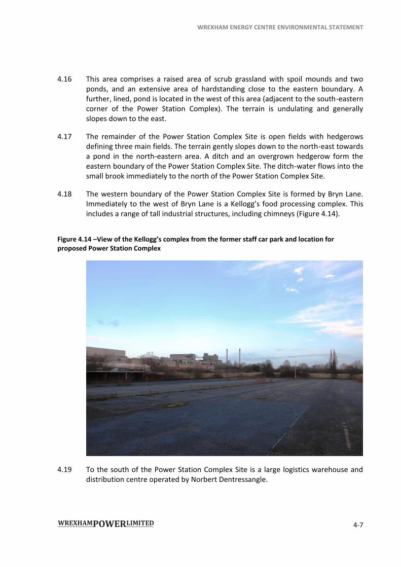
The western boundary of the Power Station Complex Site is formed by Bryn Lane. Immediately to the west of Bryn Lane is a Kellogg’s food processing complex. This includes a range of tall industrial structures, including chimneys (Figure 4.14).
Figure 4.14 –View of the Kellogg’s complex from the former staff car park and location for proposed Power Station Complex
4.19 To the south of the Power Station Complex Site is a large logistics warehouse and distribution centre operated by Norbert Dentressangle.
WREXHAM ENERGY CENTRE ENVIRONMENTAL STATEMENT
4-8
4.20 The Power Station Complex Site is bounded along its northern extents by a small brook. Immediately beyond the brook to the north is a woodland belt. This tree belt contains a number of trees which are collectively subject to a single Tree Preservation Order (TPO), a small part of which lies within the Order Limits along the entire northern boundary. This boundary feature and the overgrown hedgerow along the eastern boundary provide some visual containment at ground level.
The Gas Connection
4.21 The Gas Connection Route is approximately 3.5km in length and will largely cross a generally level area of agricultural land which is predominantly pasture and hedgerows, with pockets of woodland, a number of ponds and isolated properties. Within the Power Station Complex Site, the Gas Connection Route passes through scrubland and previously developed land.
WREXHAM ENERGY CENTRE ENVIRONMENTAL STATEMENT
4-9
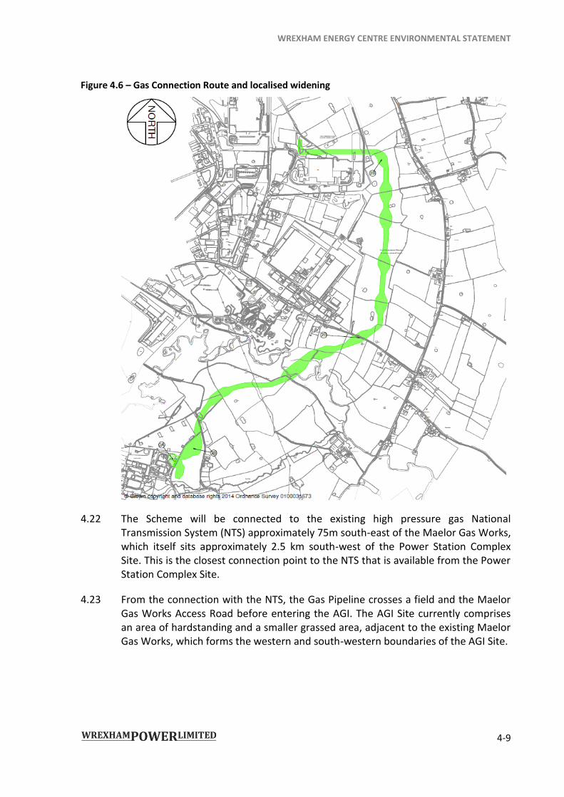
Figure 4.6 – Gas Connection Route and localised widening
4.22 The Scheme will be connected to the existing high pressure gas National Transmission System (NTS) approximately 75m south-east of the Maelor Gas Works, which itself sits approximately 2.5 km south-west of the Power Station Complex Site. This is the closest connection point to the NTS that is available from the Power Station Complex Site.
4.23 From the connection with the NTS, the Gas Pipeline crosses a field and the Maelor Gas Works Access Road before entering the AGI. The AGI Site currently comprises an area of hardstanding and a smaller grassed area, adjacent to the existing Maelor Gas Works, which forms the western and south-western boundaries of the AGI Site.
WREXHAM ENERGY CENTRE ENVIRONMENTAL STATEMENT
4-10
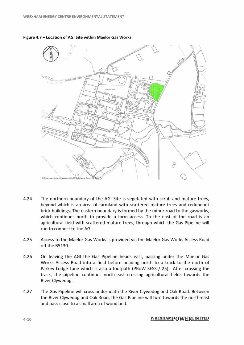
Figure 4.7 – Location of AGI Site within Maelor Gas Works
4.24 The northern boundary of the AGI Site is vegetated with scrub and mature trees, beyond which is an area of farmland with scattered mature trees and redundant brick buildings. The eastern boundary is formed by the minor road to the gasworks, which continues north to provide a farm access. To the east of the road is an agricultural field with scattered mature trees, through which the Gas Pipeline will run to connect to the AGI.
4.25 Access to the Maelor Gas Works is provided via the Maelor Gas Works Access Road off the B5130.
4.26 On leaving the AGI the Gas Pipeline heads east, passing under the Maelor Gas Works Access Road into a field before heading north to a track to the north of Parkey Lodge Lane which is also a footpath (PRoW SESS / 25). After crossing the track, the pipeline continues north-east crossing agricultural fields towards the River Clywedog.
4.27 The Gas Pipeline will cross underneath the River Clywedog and Oak Road. Between the River Clywedog and Oak Road, the Gas Pipeline will turn towards the north-east and pass close to a small area of woodland.
WREXHAM ENERGY CENTRE ENVIRONMENTAL STATEMENT
4-11
4.28 After crossing underneath Oak Road the Gas Pipeline runs north through fields to the east of WIE, crossing field boundaries marked by hedgerows, isolated trees and drainage ditches. The Gas Pipeline then crosses a Public Right of Way (PRoW, ISY / 18). Before turning west and entering the Power Station Complex Site.
4.29 The Gas Connection Route has been aligned to avoid properties, ponds, woodland and isolated trees where possible.
The locality of the Power Station Complex Site
4.30 The Power Station Complex Site is served by the Kingmoor Park Access Road from Bryn Lane, a high standard two lane road that serves as the outer ring road of the WIE. Bryn Lane joins the recently opened Wrexham Industrial Estate northern access road, a new dual carriageway that links the industrial estate to the A534 to the north providing dual carriageway access to the motorway network. A new southern access road links the industrial estate to the A525 to the south. Both the northern and southern access roads now provide the industrial estate, and hence the Scheme, with good links to the surrounding strategic highway network.
4.31 Immediately to the west lies Wrexham Industrial Estate, and, to the south, the Norbert Dentressangle logistics centre. To the north and east are agricultural fields. Other than Wrexham itself and other small settlements to the west, and the Industrial Estate, the area is rural, characterised by low lying flat landscape, intensively farmed with long views where hedgerows permit. The Clwydian Range and Dee Valley Area of Outstanding Natural Beauty (AONB) is located beyond Rhosllanerchrugog, approximately 23 km to the west.
WREXHAM ENERGY CENTRE ENVIRONMENTAL STATEMENT
4-12
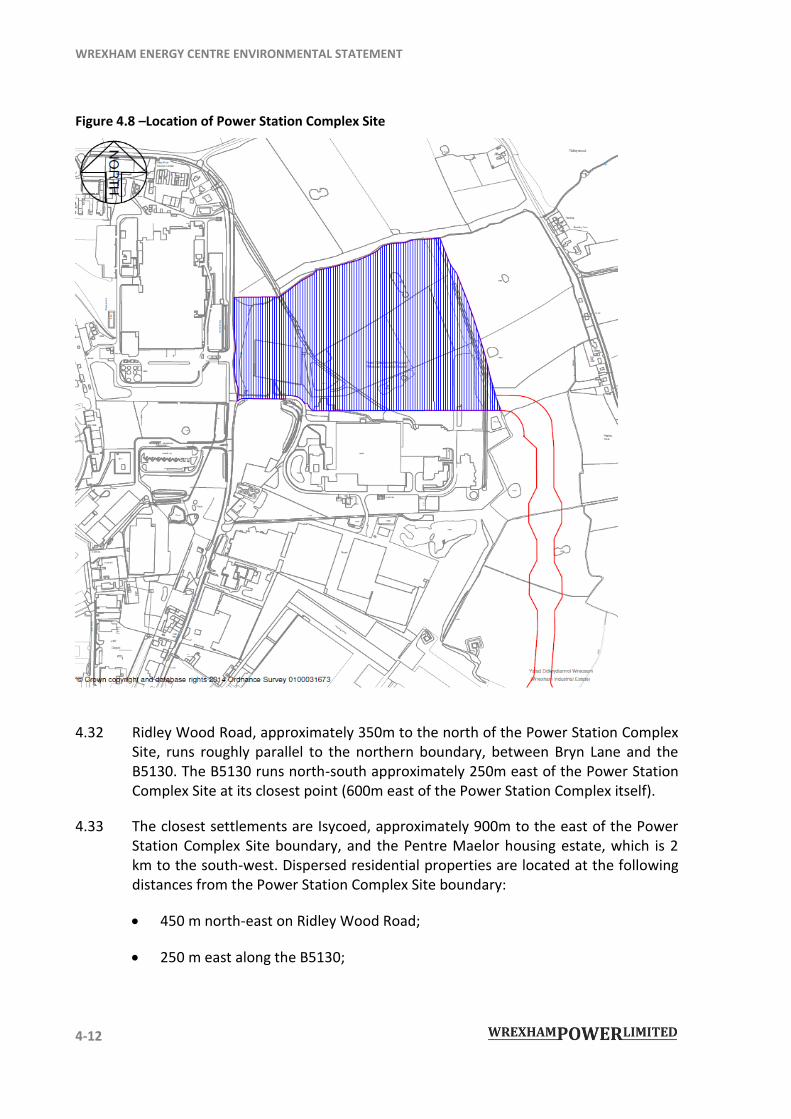
Figure 4.8 –Location of Power Station Complex Site
4.32 Ridley Wood Road, approximately 350m to the north of the Power Station Complex Site, runs roughly parallel to the northern boundary, between Bryn Lane and the B5130. The B5130 runs north-south approximately 250m east of the Power Station Complex Site at its closest point (600m east of the Power Station Complex itself).
4.33 The closest settlements are Isycoed, approximately 900m to the east of the Power Station Complex Site boundary, and the Pentre Maelor housing estate, which is 2 km to the south-west. Dispersed residential properties are located at the following distances from the Power Station Complex Site boundary:
450 m north-east on Ridley Wood Road;
250 m east along the B5130;
WREXHAM ENERGY CENTRE ENVIRONMENTAL STATEMENT
4-13
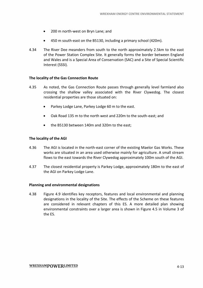
200 m north-west on Bryn Lane; and
450 m south-east on the B5130, including a primary school (420m).
4.34 The River Dee meanders from south to the north approximately 2.5km to the east of the Power Station Complex Site. It generally forms the border between England and Wales and is a Special Area of Conservation (SAC) and a Site of Special Scientific Interest (SSSI).
The locality of the Gas Connection Route
4.35 As noted, the Gas Connection Route passes through generally level farmland also crossing the shallow valley associated with the River Clywedog. The closest residential properties are those situated on:
Parkey Lodge Lane, Parkey Lodge 60 m to the east.
Oak Road 135 m to the north west and 220m to the south-east; and
the B5130 between 140m and 320m to the east;
The locality of the AGI
4.36 The AGI is located in the north-east corner of the existing Maelor Gas Works. These works are situated in an area used otherwise mainly for agriculture. A small stream flows to the east towards the River Clywedog approximately 100m south of the AGI.
4.37 The closest residential property is Parkey Lodge, approximately 180m to the east of the AGI on Parkey Lodge Lane.
Planning and environmental designations
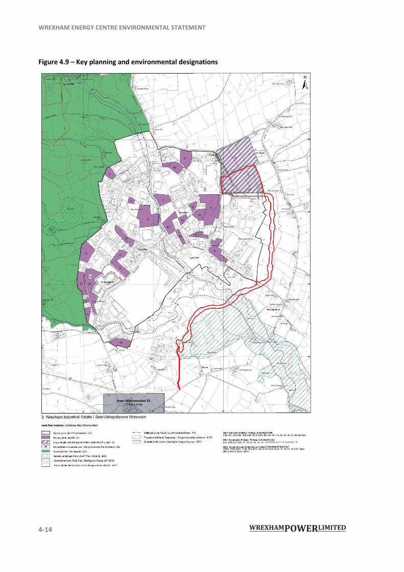
4.38 Figure 4.9 identifies key receptors, features and local environmental and planning designations in the locality of the Site. The effects of the Scheme on these features are considered in relevant chapters of this ES. A more detailed plan showing environmental constraints over a larger area is shown in Figure 4.5 in Volume 3 of the ES.
WREXHAM ENERGY CENTRE ENVIRONMENTAL STATEMENT
4-14
Figure 4.9 – Key planning and environmental designations
WREXHAM ENERGY CENTRE ENVIRONMENTAL STATEMENT
4-15
THE PROPOSED SCHEME
4.39 The Scheme comprises the construction, operation, maintenance and decommissioning of a CCGT power station (the Power Station Complex) together with infrastructure and landscaping works (the Power Station Complex Site), and the Gas Connection, providing gas from the NTS to the Power Station Complex, all of which forms part of the Scheme, known as Wrexham Energy Centre (WEC). This section provides a description of all aspects of the Scheme throughout the construction, operation, maintenance and decommissioning phases of the proposed development.
Land use requirements
4.40 Figure 4.1 shows the Order Land, which encloses an area of approximately 36.2 ha that includes approximately 19.5 ha for the Power Station Complex Site of which 3.3 ha is occupied by the Power Station Complex and 5.0 ha by landscape and ecological mitigation. The land required for the Gas Connection comprises 16.1 ha of land.
4.41 The Power Station Complex Site area will comprise the Power Station Complex situated close to the western boundary, Laydown Areas, surface water drainage and areas of ecological and landscape mitigation.
4.42 The ecological and landscape mitigation has been informed through site surveys and influenced by the surrounding landscape.
4.43 The Gas Connection Route has a nominal width of approximately 40m extending to up to 70m in certain locations due to environmental and physical constraints, and will include the permanent rights and temporary land required during construction. The approximately 40m wide route has been locally widened to enable construction through drainage ditches, hedgerows, to avoid individual trees and where the Gas Pipeline passes under Oak Road and the River Clywedog as shown in Figure 4.6 above. The permanent overall easement width to the pipe will be 12m in total. The Gas Connection Statement (Document reference 8.2) explains this in more detail.
4.44 The Electrical Connection between the Power Station Complex and SPEN’s distribution network will be consented and constructed by SPEN separately to the Application. It is thus assumed that works will be undertaken broadly at the same time as the Scheme construction works. To ensure that a robust assessment is carried out in the ES a number of realistic assumptions have been made regarding the electrical connection works as set out below:
The Electrical Connection is likely to consist of underground cabling between the Scheme’s electrical switchgear located within the Power Station Complex

WREXHAM ENERGY CENTRE ENVIRONMENTAL STATEMENT
4-16
and the existing Marchwiel substation, located on Abbey Road on the Wrexham Industrial Estate.
The wider existing electrical distribution network will also need upgrading to accommodate the new generation. This is likely to consist of works to the existing Marchwiel substation, re-stringing of existing pylons between Legacy and Wrexham substations, replacement of the existing portal frame towers between Legacy and Marchwiel substations, and laying of underground cables. Once completed the electrical network which currently serves the Wrexham Industrial Estate will have increased capacity and resilience from that which exists presently.
4.45 The final technical solution for the Electrical Connection will be determined at a later date by SPEN in their role as statutory undertaker for electrical infrastructure in the area. Any works associated with the Electrical Connection will be consented through the appropriate and lawful consenting regime. An Environmental Impact Assessment, if required, may be carried out as part of that consenting process. Further details of the Electrical Connection and the consultation undertaken with SPEN to date are detailed in the Grid Connection Statement (Document Ref: 8.1).
Operational requirements
Process Description
4.46 A CCGT power station uses an efficient combination of gas and steam turbines to generate electricity. In the gas turbine, air is compressed and passed into a combustion chamber where it is mixed with natural gas fuel to produce hot combustion gases at high pressure. This thermal and pressure energy is converted to mechanical energy by expanding the combustion gas through the gas turbine, which drives a power turbine and air compressor. The power turbine is connected to a generator that produces electrical power. The hot exhaust gases from the gas turbine are passed to an unfired boiler (usually referred to as a heat recovery steam generator or HRSG) to produce steam. This steam is passed through a steam turbine to drive another generator to produce more electrical power.
4.47 The Power Station Complex is designed to operate 24 hours a day, 7 days a week, although the precise operational hours will be dependent on electricity demand. For the purposes of the EIA it has been assumed that the WEC would operate continuously to present the realistic worst case scenario for assessment purposes.
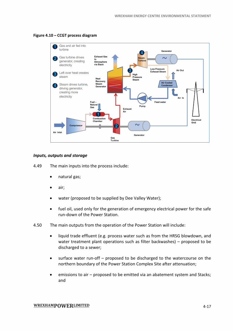
4.48 Figure 4.10 provides a diagrammatic summary of how a CCGT power station works.
WREXHAM ENERGY CENTRE ENVIRONMENTAL STATEMENT
4-17
Figure 4.10 – CCGT process diagram
Inputs, outputs and storage
4.49 The main inputs into the process include:
natural gas;
air;
water (proposed to be supplied by Dee Valley Water);
fuel oil, used only for the generation of emergency electrical power for the safe run-down of the Power Station.
4.50 The main outputs from the operation of the Power Station will include:
liquid trade effluent (e.g. process water such as from the HRSG blowdown, and water treatment plant operations such as filter backwashes) – proposed to be discharged to a sewer;
surface water run-off – proposed to be discharged to the watercourse on the northern boundary of the Power Station Complex Site after attenuation;
emissions to air – proposed to be emitted via an abatement system and Stacks; and
WREXHAM ENERGY CENTRE ENVIRONMENTAL STATEMENT
4-18
waste – in minor quantities, such as office waste, used oil, filter cartridges and grounds maintenance. There will be virtually no waste arising directly from the electricity generation process itself.
4.51 There would be no storage of gas on the Site other than the volume contained within the Gas Pipeline. The water treatment plant would have a related raw water storage tank and a demineralised water storage tank.
4.52 Chapter 8: Air Quality of this ES has assessed the potential effects of the Scheme on air quality using atmospheric dispersion modelling of emissions to the atmosphere from the WEC stacks. Other emissions relating to noise and vibration are considered in Chapter 9: Noise of this ES, and waste generation connected with the operation of the Scheme is assessed in Chapter 15: Waste.
Maintenance activities and requirements
4.53 The EIA assesses both the operation and maintenance of the Scheme. Each technical assessment chapter includes maintenance activities, where relevant to that discipline, within the assessment of operational impacts.
4.54 The plant will be designed to operate 24 hours a day, 7 days a week, other than during scheduled annual shutdowns, and will be capable of generating power at 100% Maximum Continuous Rating (MCR) for a minimum of 8,322 hours per annum. Details in relation to maintenance are included in the following paragraphs.
4.55 The Scheme will operate with approximately 30 staff working on a shift basis. This number will increase during routine maintenance and shutdown activities, as described below.
4.56 For the purposes of the assessments contained in this ES, maintenance activities include inspect, repair, adjust, alter, remove, refurbish, reconstruct, replace and improve any part, but not the whole, of the authorised development and “maintenance” and “maintaining” are to be construed accordingly.
4.57 These activities are summarised below.
Inspection of key equipment on Site, such as gas and steam turbines, pressured steam systems and HRSG, both routine daily inspections and more thorough intrusive inspections carried out during scheduled shutdown periods in order to monitor wear and tear and identify and report any damage of the equipment.
Repair - damaged components can be sent for sampling or testing to establish the cause of damage and whether repairs are required immediately. Otherwise, during annual scheduled shutdown periods repairs can be carried out on damaged equipment identified during inspections.
WREXHAM ENERGY CENTRE ENVIRONMENTAL STATEMENT
4-19
Adjustments or alterations to the equipment to improve the operation of the plant.
Removal - during scheduled shutdowns equipment can be removed to be repaired or replaced.
Replacement - it is likely that during the WEC’s design life certain plant equipment, such as pumps and fans, will require replacement. This would occur during the scheduled shutdown period when necessary. The gas and steam turbines, HRSG(s) and air cooled condenser would not be expected to be replaced as a whole during the design life of the Scheme, although components of each are likely to need replacing over time due to wear and tear.
Reconstruction of equipment once intrusive inspections and/or repairs have been carried out, when components have to be removed.
Routine maintenance
4.58 Typical daily inspections and maintenance when the WEC is in operation would be restricted to activities such as inspections of pressurised steam systems, turbines and generator, greasing and oiling, and other minor maintenance tasks.
4.59 For assessment purposes it has been assumed that one HGV will visit the Power Station Complex Site per day for routine maintenance and repair activities outside of the shutdown periods.
4.60 The majority of routine maintenance would take place within the buildings on site, reducing the noise produced by these activities.
4.61 Other routine activities would include maintenance of landscaped areas, maintenance, repairs and supply to office, canteen and other staff facilities on site.
Shutdown Periods
4.62 Temporary shutdown of the WEC will be required on an annual basis for various maintenance activities. These include but are not limited to:
annual inspection of gas turbine combustion components (3-7 days’ shutdown period), and inspection of the HRSG and steam system pressure containment components;
removal of gas turbine casings every three to four years for closer inspection of the hot gas path parts within the gas turbine, including removal and replacement of damaged turbine blades. Inspections will be made to the steam turbine last stage blades. The generators will be checked for dust and damage
WREXHAM ENERGY CENTRE ENVIRONMENTAL STATEMENT
4-20
to the stator end windings and subjected to non-intrusive electrical testing (an approximate two-week shutdown period); and
intrusive inspection of the gas and steam turbine static and rotating components every six to eight years, replacing any components that show damage or are life-expired. Intrusive inspections will also be undertaken of the steam system and HRSG pressure containing parts such as steam vessels and steam system header pipes. Non-destructive testing will be conducted and any damaged components repaired or replaced, (approximately one-month shutdown period).
4.63 The annual maintenance shutdown is likely to be completed largely by external contractors, with staff numbers estimated to be in the order of 80 people. The longer period works could require a further 50 staff. This would entail some extra operational light traffic to the WEC for the purposes of staff transport. It is likely that the extra staff will work on a shift basis so arrivals will be staggered.
4.64 The majority of maintenance work would take place within the Power Station Complex buildings, reducing the potential for external dust and noise emissions, particularly when cutting and welding tools are in use. However, there might be a need to use the permanent Laydown Area, as shown on Works Plan, ‘Work Package 2B’ (Document reference 2.3) area if items of equipment need more room for inspection or maintenance. This would require a weather-proof temporary structure – essentially a marquee – to protect equipment. It could be approximately 10m by 20m and could be erected within the Power Station Complex’s permanent Laydown Area or on ground adjacent to Power Station Complex buildings.
4.65 If additional car parking was required this would be made available in the permanent Laydown Area, immediately adjacent to the Power Station Complex.
Above Ground Installation
4.66 The AGI would be visited approximately once a year for maintenance purposes using a light vehicle via the existing access and track off the B5130. This is not expected to involve any significant works, rather the inspection and minor repair of equipment, an activity that would be contained within the AGI.
Gas Connection
4.67 Inspection of the pipeline will be via a pipeline inspection gauge (PIG) inserted at the AGI. It is not anticipated that the pipeline would require intrusive maintenance (i.e. work that would require digging a trench to expose the pipeline) during the lifetime of the Scheme. Aerial surveys and ‘line walks’ of the route might be required occasionally to ensure there are no works have taken place near the pipeline that might damage its physical and operational integrity.
WREXHAM ENERGY CENTRE ENVIRONMENTAL STATEMENT
4-21
DESCRIPTION OF THE COMPONENTS
4.68 The Scheme includes the following components:
the Power Station Complex, including a CCGT power station that is “CHP ready”, i.e. has the potential for combined heat and power;
the Gas Connection (comprising AGI and Gas Pipeline);
access roads (including alteration to the Kingmoor Park Access Road);
temporary and permanent Laydown Areas;
surface water drainage;
foul water drainage;
landscaping;
ecological mitigation;
security equipment and fencing; and
lighting.
4.69 These components are described below.
The Power Station Complex
4.70 The Power Station Complex comprises the following components.
Gas Turbine Building, which contains up to two gas turbines, each connected to its own generator. In the gas turbine, air is compressed and passed into a combustion chamber where it is mixed with natural gas fuel to produce hot combustion gases at high pressure. This thermal and pressure energy is converted to mechanical energy by expanding the combustion gas through the gas turbine. The power turbine is connected to a generator that produces electrical power.
Up to two Heat Recovery Steam Generators Buildings and Stacks. The hot exhaust gases from each gas turbine are passed to an HRSG to recover heat and produce steam before being sent to the stack or stacks for release to the atmosphere.
Steam Turbine Building with one steam turbine connected to a generator. The steam produced by the HRSG is used to drive a steam turbine and produce more electrical power.
WREXHAM ENERGY CENTRE ENVIRONMENTAL STATEMENT
4-22
Water Treatment Plant and Water Storage Tanks to supply and store demineralised water and process water. The water treatment plant shall be specified with 2 x 100% streams (i.e. there will be two parallel sets of equipment each of which is capable of treating 100% of the required water – so one can be taken offline for maintenance and the other can still cope with the required flow). A demineralised water tank would be provided with 2 x 100% feed-water make-up pumps. The make-up water for the water treatment plant is anticipated to be provided by the local water supply company, Dee Valley Water.
Air Cooled Condenser – in which the exhaust steam from the steam turbine is cooled and condensed to feed-water using ambient air as the cooling medium.
Main and auxiliary step-up Transformers for each gas and steam turbine.
Electrical Switchgear – which is anticipated to comprise a combination of Air-insulated Switchgear (AIS) and Gas-insulated Switchgear (GIS). It would be designed to enable the full Scheme output to be exported to Marchwiel substation.
Pressure Regulating Installation (PRI) – which would receive the supply of gas from the National Transmission System (NTS). The PRI will comprise gas conditioning, pressure regulation and possible heating equipment.
Heat Network Interface - the Energy Efficiency Directive requires new plants over 20MWe to allow for recovery of heat to supply to nearby consumers. There is potential for a future district heating network to serve the WIE, for which the Scheme would be the major heat supplier. At the time of writing the local heat demand has not been quantified. However, the indicative Power Station Complex layout makes provision for a Heat Interface Building to accommodate necessary equipment, should a heating scheme be deemed viable.
Control and Administration Building to contain staff and contractor offices and the main plant control room.
Workshop and Stores for maintenance activities and the storage of chemicals and tools.
Foul Water Drainage and Pumping Station for the conveyance of trade effluent and domestic foul water to an underground foul water pumping station from where it will be pumped to Welsh Water’s local foul water sewerage network.
Parking spaces for up to 20 vehicles.
Cabling and other services
WREXHAM ENERGY CENTRE ENVIRONMENTAL STATEMENT
4-23
Roads accessing the various elements of the Power Station Complex, from the main Power Station Complex entrance.
Security Fencing, Gatehouse and access gates around the Power Station Complex, up to 2.5m in height.
External lighting - including street lights within the Power Station Complex and lighting of the perimeter fence.
4.71 At this stage there is flexibility in the design of the turbines, generators and stacks. Each of these components and the various scenarios are discussed in more detail below. The other integral supporting infrastructure at the Power Station Complex Site, including the steam turbine building transformers, switchgear room, a 132kV switchyard, air cooled condenser, water tanks, water treatment system, administration building, pressure regulating installation, store/workshop, heat interface building, security fencing, gatehouse, lighting, roadways and parking, will remain constant, no matter which design is chosen.
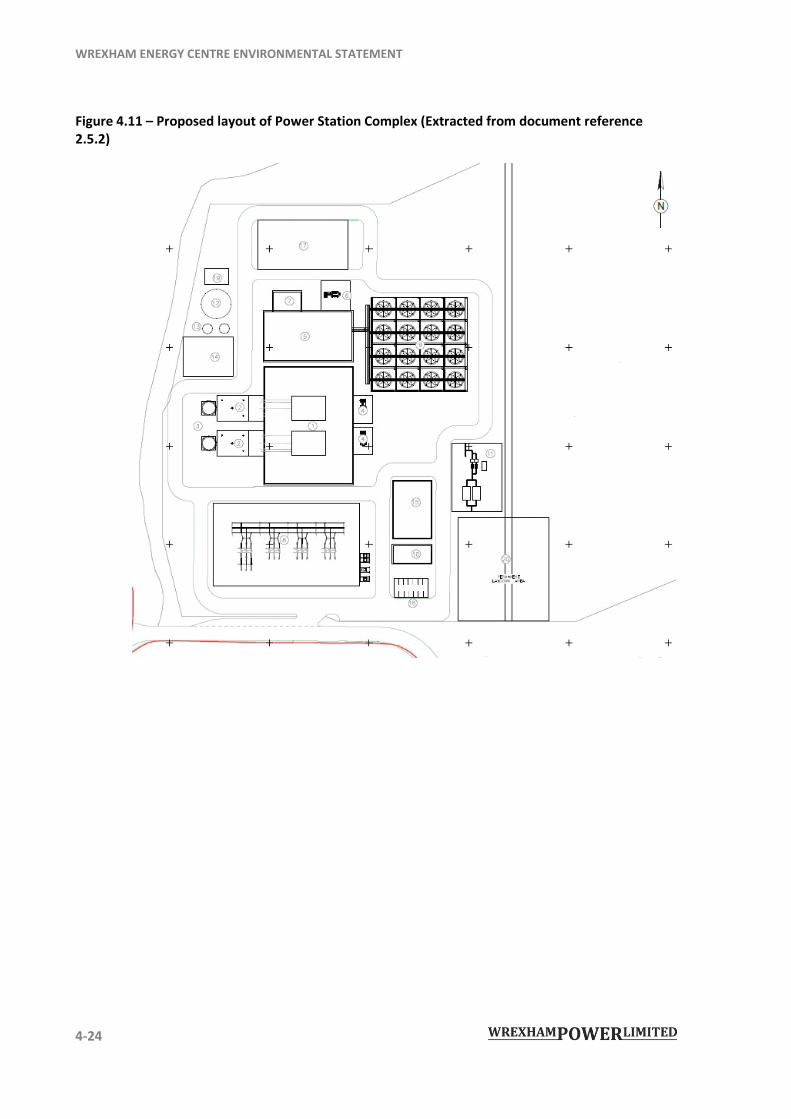
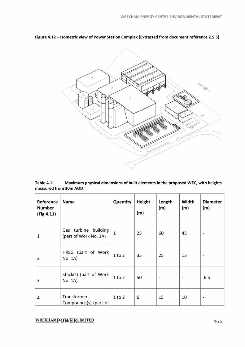
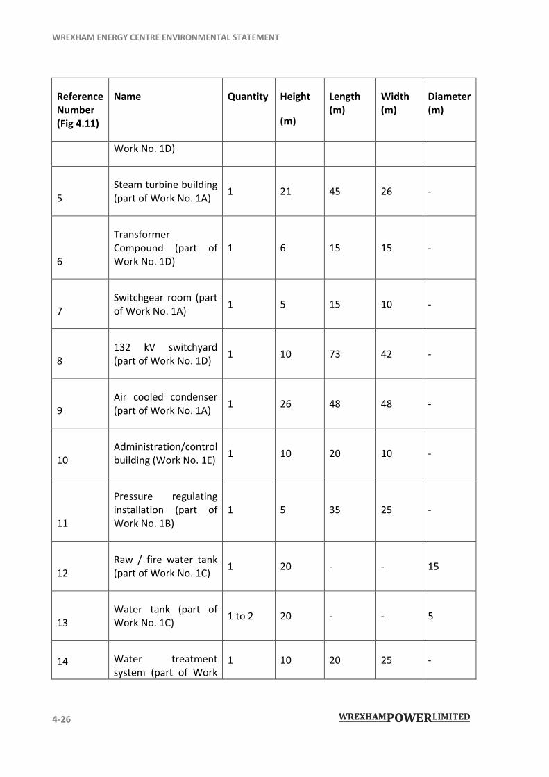
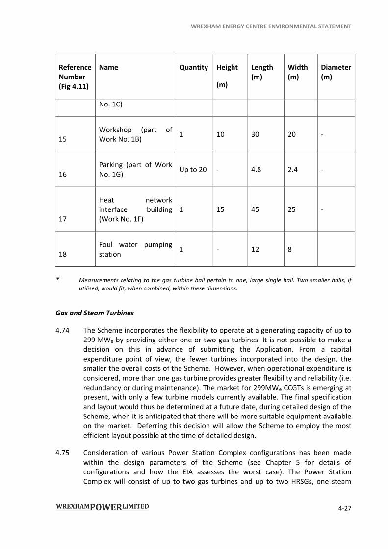
4.72 Table 4.1 identifies the maximum physical dimensions of the structures that comprise the Power Station Complex. Unless otherwise stated all physical dimensions are taken from a maximum 30m AOD.
4.73 Figure 4.11 shows the layout of the Power Station Complex and Figure 4.12 shows an isometric view of the Power Station Complex. The numbers shown on the plan are referenced in Table 4.1, below and can also be found on document references 4.5.1 to 4.5.5.
WREXHAM ENERGY CENTRE ENVIRONMENTAL STATEMENT
4-24
Figure 4.11 – Proposed layout of Power Station Complex (Extracted from document reference 2.5.2)
WREXHAM ENERGY CENTRE ENVIRONMENTAL STATEMENT
4-25
Figure 4.12 – Isometric view of Power Station Complex (Extracted from document reference 2.5.5)
Table 4.1: Maximum physical dimensions of built elements in the proposed WEC, with heights measured from 30m AOD
Reference Number (Fig 4.11)
Name Quantity Height
(m)
Length (m)
Width (m)
Diameter (m)
1 Gas turbine building (part of Work No. 1A)
1 25 60 45 -
2 HRSG (part of Work No. 1A)
1 to 2 35 25 13 -
3 Stack(s) (part of Work No. 1A)
1 to 2 50 - - 6.5
4 Transformer Compounds(s) (part of
1 to 2 6 15 10 -
WREXHAM ENERGY CENTRE ENVIRONMENTAL STATEMENT
4-26
Reference Number (Fig 4.11)
Name Quantity Height
(m)
Length (m)
Width (m)
Diameter (m)
Work No. 1D)
5 Steam turbine building (part of Work No. 1A)
1 21 45 26 -
6
Transformer Compound (part of Work No. 1D)
1 6 15 15 -
7 Switchgear room (part of Work No. 1A)
1 5 15 10 -
8 132 kV switchyard (part of Work No. 1D)
1 10 73 42 -
9 Air cooled condenser (part of Work No. 1A)
1 26 48 48 -
10 Administration/control building (Work No. 1E)
1 10 20 10 -
11
Pressure regulating installation (part of Work No. 1B)
1 5 35 25 -
12 Raw / fire water tank (part of Work No. 1C)
1 20 - - 15
13 Water tank (part of Work No. 1C)
1 to 2 20 - - 5
14 Water treatment system (part of Work
1 10 20 25 -
WREXHAM ENERGY CENTRE ENVIRONMENTAL STATEMENT
4-27
Reference Number (Fig 4.11)
Name Quantity Height
(m)
Length (m)
Width (m)
Diameter (m)
No. 1C)
15 Workshop (part of Work No. 1B)
1 10 30 20 -
16 Parking (part of Work No. 1G)
Up to 20 - 4.8 2.4 -
17
Heat network interface building (Work No. 1F)
1 15 45 25 -
18 Foul water pumping station
1 - 12 8
* Measurements relating to the gas turbine hall pertain to one, large single hall. Two smaller halls, if
utilised, would fit, when combined, within these dimensions.
Gas and Steam Turbines
4.74 The Scheme incorporates the flexibility to operate at a generating capacity of up to 299 MWe by providing either one or two gas turbines. It is not possible to make a decision on this in advance of submitting the Application. From a capital expenditure point of view, the fewer turbines incorporated into the design, the smaller the overall costs of the Scheme. However, when operational expenditure is considered, more than one gas turbine provides greater flexibility and reliability (i.e. redundancy or during maintenance). The market for 299MWe CCGTs is emerging at present, with only a few turbine models currently available. The final specification and layout would thus be determined at a future date, during detailed design of the Scheme, when it is anticipated that there will be more suitable equipment available on the market. Deferring this decision will allow the Scheme to employ the most efficient layout possible at the time of detailed design.
4.75 Consideration of various Power Station Complex configurations has been made within the design parameters of the Scheme (see Chapter 5 for details of configurations and how the EIA assesses the worst case). The Power Station Complex will consist of up to two gas turbines and up to two HRSGs, one steam
WREXHAM ENERGY CENTRE ENVIRONMENTAL STATEMENT
4-28
turbine, and a generator for each turbine (a ‘2+1’ arrangement). It could equally comprise a single larger gas turbine, one HRSG, one, steam turbine and two separate generators (a ‘1+1’ arrangement). The two arrangements examined (2+1 and 1+1) were chosen based on what is best available in the current market to achieve an electricity generation capacity of up to 299MWe.
4.76 Based on existing technology, the exemplar gas turbine technology options related to the above two configurations, and assessed in this ES, are:
a GE 206FA combined cycle dual gas turbine unit of 235 MWe output comprising two 6FA gas turbines each with their own HRSG and related exhaust stack (individual or combined); and
an Alstom GT13E2 combined cycle unit of approximately 290 MWe output, with a single gas turbine and HRSG configuration and a single exhaust stack.
4.77 With respect to the footprints and size of buildings required to accommodate the two proposed layouts, a 2+1 arrangement is considered to fit on a site of the same order of magnitude as a 1+1 arrangement. However, as a worst case scenario a 2+1 arrangement might require a single, larger gas turbine hall, or two separate gas turbine buildings with combined dimensions no greater than that of a 1+1 layout.
4.78 The requirements for two HRSGs and potentially a larger turbine building mean that the 2+1 layout would be of a greater overall mass and take up a larger area than a 1+1 layout. The 2+1 layout is therefore considered to be a realistic worst case and therefore represents the largest extent of the Power Station Complex layout.
4.79 The turbines and generators would be located in turbine buildings (the steam turbine and its generator will be located within a separate turbine building to the gas turbine(s) and their generators), equipped with internal overhead gantry cranes for maintenance. Maintenance will generally take place within the buildings or on the permanent Laydown Area, under temporary covers as necessary.
Heat Recovery Steam Generator
4.80 Each gas turbine has a HRSG for the recovery of heat and production of steam from the gas turbine exhaust for further electricity generation. The 2+1 arrangement has two HRSGs, while only one is required for the 1+1 arrangement. The 2+1 arrangement therefore represents a realistic worst case with regard to building mass and footprint.
Vent Stack(s)
4.81 Each HRSG has its own exhaust flue contained within a stack, of which there will be either one or two, with continuous emissions monitoring devices (CEMs) installed.
WREXHAM ENERGY CENTRE ENVIRONMENTAL STATEMENT
4-29
Landscape and visual constraints have set 50m as the maximum stack height, and 6.5m as the maximum stack diameter.
4.82 For the 2+1 and 1+1 arrangements, three stack arrangements are possible:
a 2+1 arrangement, with two separate stacks;
a 2+1 arrangement, with two flues combined in a single outer stack; or
a 1+1 arrangement, with a single stack.
4.83 The 2+1 arrangement with two stacks represents the realistic worst case with regard to building mass and dimensions. It also represents the realistic worst case with regard to air quality, as the 2+1 arrangement with two separate stacks was found to give the highest ground level concentrations at human health and ecological receptors of the different arrangements tested. A stack height range of 46 to 50m was deemed, by means of initial dispersion modelling, to be acceptable for the 2+1 arrangement with two stacks. Further discussion of stack heights and arrangements is set out in Chapter 8: Air Quality.
4.84 Each stack would have necessary steel structures, stairways, ladders, walkways and a minimum of two maintenance platforms; one for access to the CEMs and other testing equipment, and one at the top of the stack.
Cooling Systems
4.85 The cooling medium for exhaust steam will be air, via a dry air-cooled condenser for all turbine configurations. The condenser would be capable of condensing 100% of the HRSG’s steam output meaning that the steam will be contained within the Power Station Complex during normal operation.
Water Treatment Plant
4.86 A water treatment plant would be installed to provide demineralised water for the Power Station Complex steam system for all turbine configurations. The make-up water for the water treatment plant will be provided by the local water supply company, Dee Valley Water.
Switchgear
4.87 For operational safety and the export of the electricity generated by the Power Station Complex, the following electrical systems would be included:
main step-up transformers;
WREXHAM ENERGY CENTRE ENVIRONMENTAL STATEMENT
4-30
auxiliary transformers;
LV and HV switchgear;
uninterruptable Power Supply (UPS);
electrical protection; and
earthing.
Electrical Connection
4.88 The Power Station Complex’s output would be exported into SPEN’s 132 kV network via underground cables running to the Marchwiel substation, approximately 470 m to the south-west of the Power Station Complex Site. Network reinforcement works are also expected to form part of the Electrical Connection.
4.89 The connection into the SPEN network will be designed to enable a single generator circuit to be shut down for maintenance without affecting the operation of the remaining connections.
4.90 The Electrical Connection does not form part of the Application and is therefore not included in the operational aspects of this ES. However, the cumulative effects of the construction and operation of the Electrical Connection and the Scheme are assessed in the relevant chapters of this ES. A description of the Electrical Connection is provided in the cumulative development section of Chapter 5 of this ES.
Gas Connection and AGI
4.91 The Power Station Complex will need to obtain gas from National Grid’s gas network, the NTS. The closest connection point to the Power Station Complex is approximately 2.2 km to the south-west, where the NTS supplies Maelor Gasworks. An AGI will be constructed adjacent to these works. The integral underground connection to the NTS will be made in the field to the south-east of the AGI. The exact location of the connection will be National Grid’s decision, but the Order Land provide an adequate area for this integral connection to be made.
4.92 The design of the integral Gas Connection has taken account of the demand of the proposed Power Station Complex and the maximum capacity and pressure available from the network in the area.
4.93 The AGI would comprise an approximate 46m by 47m compound, secured by fencing with a maximum height of 2.5m. The compound would contain instrument kiosks, a series of pipes and valves with a flow meter, isolation control valves, and a pipeline inspection gauge (PIG) function for cleaning and inspection. From this
WREXHAM ENERGY CENTRE ENVIRONMENTAL STATEMENT
4-31
compound natural gas would be conveyed to the Power Station Complex by means of a pipeline with a maximum diameter of 400 mm.
4.94 The integral Gas Connection between the PRI in the Power Station Complex and the AGI is approximately 3.5 km in length, including the portions in the Power Station Complex Site and Gas Connection Route. The pipeline would be underground for its entire length.
4.95 A gas receiving station for the supply and metering of gas to the gas turbines, the PRI, would be located within the main Power Station Complex. The Power Station Complex would include all necessary gas processing equipment, including:
PIG trap or launcher, if necessary and as appropriate;
gas scrubber;
filtering;
metering and telemetry;
pressure regulation; and
electrical heaters for heating gas.
4.96 There would be no storage of natural gas on the Power Station Complex Site other than the volume of gas in the integral Gas Connection and the pipework feeding gas to the gas turbines.
4.97 A small volume of light fuel oil or similar would be stored in the Power Station Complex for use as a back-up fuel, to drive emergency equipment and for generation of emergency electrical power to enable a safe run-down of the Power Station Complex when electricity is unavailable either from the external grid or the station itself. The back-up generators and equipment do not form part of the Scheme’s power export capability. See Work Numbers 1B(c) of Schedule 1 of the Order.
Access Roads
4.98 Road access to the Power Station Complex Site would be via the existing Kingmoor Park Access Road, into Kingmoor Park South Industrial Estate, which connects to Bryn Lane. Bryn Lane is a high standard two lane road which serves as the outer ring road of the industrial estate and provides good access to the strategic highway network.
4.99 Access to the AGI will be via the existing Maelor Gas Works Access Road to the Maelor Gas Works off the B5130. Outside of the shutdown maintenance periods
WREXHAM ENERGY CENTRE ENVIRONMENTAL STATEMENT
4-32
noted above at 4.50, day-to-day operating traffic is likely to consist of up to 30 light vehicle movements (for staff) per day and one HGV movement.
Power Station Complex Internal Site roads
4.100 Within the Power Station Complex access, roads are required to allow the movement of staff employed at the Site, maintenance vehicles and emergency vehicles. These roads range from 5 to 7 m in width, which would typically comprise around 250 mm bituminous construction founded on a sub-base layer, with or without an additional capping layer depending on local ground conditions.
Parking
4.101 Up to 20 car parking spaces would be provided for operational staff within the southern part of the Power Station Complex to enable easy access to the facilities.
Surface Water Drainage
4.102 All run-off from impermeable areas such as roofs, hardstanding and highway areas at the Power Station Complex Site will be intercepted by trapped gullies, permeable paving or filter drains to the surface water storage / attenuation area via a system of pipework. Surface water will then flow along an open channel or swale to the ponds in the north eastern corner of the Power Station Complex Site prior to discharge into the watercourse along the northern boundary.
4.103 The performance requirements for the surface water drainage system are as follows:
in accordance with Natural Resources Wales’s and Wrexham Borough Council’s requirements, the maximum permitted discharge rate from the proposed Power Station Complex Site into the local watercourse network would be limited to existing annual average greenfield runoff rate of 3.7 litres/sec/ha, the Power Station Complex Site being 3.3 ha. This equates to a discharge rate of 12.2 litres/sec which will apply to all rainfall events up to and including the 1 in 100-year +20% event;
any flooding occurring within the proposed development for up to and including the 1 in 100-year +20% event will be contained within the Power Station Complex Site in a safe manner and allowed to discharge at the above mentioned rate.
Further detail is provided in the Foul and Surface Water Drainage Strategy, which is appended to chapter 14 of this ES.
WREXHAM ENERGY CENTRE ENVIRONMENTAL STATEMENT
4-33
Foul Water Drainage
4.104 The cooling water system and HRSG will periodically emit spent cooling and washdown water as a part of normal operations and maintenance. This will be directed to the foul water system and treated as trade effluent, as described in the drainage strategy for the Scheme.
4.105 The trade effluent from the plant and domestic foul water flows would be directed via underground pipes to a foul water pumping station, located in the north-west of the Power Station Complex. From here the foul water would be pumped to Welsh Water’s local foul water sewerage network along Bryn Lane under separate consents to this DCO, to a Welsh Water combined sewer manhole approximately 130m south of the Power Station Complex Site. This connection would be provided by Welsh Water as part of a foul water sewage connection requisition under the terms of the Water Industry Act 1991.
4.106 The foul water pumping station will be either a packaged system purchased ‘off the shelf’ to suit the flows and pumping requirements or an in-situ constructed manhole with two pumps alternating in the duty and stand-by roles. Each option will be controlled by equipment located within the admin/control building.
Combined Heat and Power (CHP)
4.107 As described in paragraph 4.68 of this ES, the Government's policy is that surplus heat from power stations should be used, where possible, for community heating and industrial uses. This ES therefore assesses a CCGT power station that is ‘CHP ready’ and space for the related heat interface building.
Landscaping
4.108 The drawings included as document references 2.9.1 to 2.9.7 show the illustrative landscape treatment for the Scheme. Document reference 2.9.1 shows the Power Station Complex Site and includes the following mitigation areas that reflect landscape, drainage and ecological considerations for the integration of the WEC into the local context, providing screening to protect views from the east and enhancing habitat diversity:
compensation for the loss of a lined pond associated with the former fibreglass factory through a cluster of three new ponds provided in the north-eastern corner of the Power Station Complex Site. These ponds would also form part of the Power Station Complex Site drainage strategy and will provide Great Crested Newt (GCN) mitigation, marginal wetland planting and refugia mounds for amphibians;
WREXHAM ENERGY CENTRE ENVIRONMENTAL STATEMENT
4-34
provision of a new woodland belt and a bund on the eastern side of the Power Station Complex Site to compensate for the loss of trees along the eastern boundary of the Power Station Complex and to provide screening of the Power Station Complex and Wrexham Industrial Estate in views from properties to the east along the B5130. This woodland area would also provide a link to the tree belt to the north of the Power Station Complex Site; and
provision of an ecological mitigation area along the northern section of the Power Station Complex Site, comprising open grassland habitat to compensate for the loss of semi-improved grassland. This will comprise a hay / wildflower meadow, refuge for invertebrates and reptiles and a hedge bank along the southern edge adjacent to the ditch / swale. The swale will provide the boundary between the ecological mitigation area and the remainder of the Power Station Complex Site.
Document references 2.9.2 to 2.9.7 refer to the Gas Connection Route and demonstrate how the Scheme includes provision for the replacement of hedgerow sections removed during construction.
Security
4.109 Security fencing of up to 2.5m in height is proposed along the perimeter of the Power Station Complex Site. Access and egress may be controlled from an entrance gatehouse or from the administration block.
Lighting
4.110 External lighting would comprise street lights for roads, walkways and areas required for access to plant within the Power Station Complex and lighting of the perimeter fence. Operational areas would be lit 24 hours a day. External lighting would be designed to reduce light pollution.
CONSTRUCTION
Programme
4.111 For the purposes of the EIA, the programme envisages an overall construction period of 36 months. Protective measures during this period are set out in the draft Construction Environmental Management Plan (CEMP) included as Appendix 19.1 to this ES. There are three key periods within the construction programme, with some overlap in activities anticipated. Construction would begin with the enabling works, which will include site set-up, vegetation removal, landscaping and ground remediation (if required) and would take up to 8 to 10 months. Following the
WREXHAM ENERGY CENTRE ENVIRONMENTAL STATEMENT
4-35
enabling works, construction of the Power Station Complex and Gas Connection would be undertaken over a period of approximately 20 months (months 8 to 28), with commissioning taking up to eleven months (month 25-36).
Power Station Complex Site
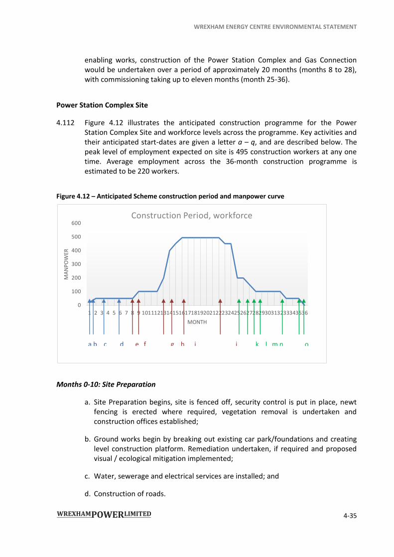
4.112 Figure 4.12 illustrates the anticipated construction programme for the Power Station Complex Site and workforce levels across the programme. Key activities and their anticipated start-dates are given a letter a – q, and are described below. The peak level of employment expected on site is 495 construction workers at any one time. Average employment across the 36-month construction programme is estimated to be 220 workers.
Figure 4.12 – Anticipated Scheme construction period and manpower curve
Months 0-10: Site Preparation
a. Site Preparation begins, site is fenced off, security control is put in place, newt fencing is erected where required, vegetation removal is undertaken and construction offices established;
b. Ground works begin by breaking out existing car park/foundations and creating level construction platform. Remediation undertaken, if required and proposed visual / ecological mitigation implemented;
c. Water, sewerage and electrical services are installed; and
d. Construction of roads.
0
100
200
300
400
500
600
1 2 3 4 5 6 7 8 9 101112131415161718192021222324252627282930313233343536
MA
NP
OW
ER
MONTH
Construction Period, workforce
a b c d e f g h i j k l m n o
WREXHAM ENERGY CENTRE ENVIRONMENTAL STATEMENT
4-36
Months 8-28: Main Construction
a. Main construction begins with the setting out and excavation of foundations;
b. Construction of foundations of the gas turbine and steam turbine halls, the air-cooled condenser and the stack(s);
c. Fabrication of buildings, including turbine hall(s), admin building, control room and workshop;
d. Installation of mechanical equipment, including turbine(s);
e. Pipework fabrication and installation; and
f. Control/ electrical equipment and instrumentation installed.
Months 25-36: Commissioning
a. Safety checks and hydrostatic pressure testing carried out;
b. Auxiliary plant systems are commissioned first to provide logistical support for turbine operation. These auxiliary systems include water treatment, gas supply, flue gas exhaust emissions and electrical and transmission network;
c. Motors, pumps and control circuits are commissioned;
d. All water, steam and auxiliary pipework is cleaned prior to turbine commissioning;
e. Turbine commissioning;
f. Removal of construction offices; and
g. Completion.
Gas Connection
4.113 It is anticipated that the construction of the Gas Connection will take 16 to 20 weeks and will employ 20 workers at the busiest period.
4.114 The site preparation phase will include:
land management arrangements;
setting out and fencing; and
hedgerow removal (winter only).
WREXHAM ENERGY CENTRE ENVIRONMENTAL STATEMENT
4-37
4.115 The main construction period will include:
topsoil stripping;
trial holes and drainage;
open cut trenching / directional drilling;
stringing, welding and coating;
installation and backfilling; and
reinstatement of land drainage and hedgerows.
4.116 Unless otherwise agreed with the local authority, proposed construction working hours for the entire Scheme are 07:00-19:00 Monday to Friday and 07:00-13:00 on Saturdays and Public Holidays, except during concrete pouring, delivery of abnormal loads and 24-hour security, as set out in the Requirements of the proposed DCO (see Schedule 2 to the draft Order (Document reference 3.1)).
Construction traffic
Transport routes for construction vehicles
4.117 Details of the volumes, routes and patterns of construction traffic connected with the Scheme are detailed within Chapter 7: Transport and Traffic of this ES.
4.118 Construction traffic delivering materials to the Power Station Complex Site (i.e. HGVs) would use the route from the north via the A534, new northern access road and Bryn Lane before turning left into Kingmoor Park Access Road and then into the Power Station Complex Site.
4.119 All construction staff visiting the site will also be required to access and exit the site via Bryn Lane, new northern access road and A534, in order to avoid more sensitive roads such as Ridley Wood Road and the village of Hugmore.
4.120 Construction traffic delivering materials to the AGI will use the A525, B5130 and the Maelor Gas Works Access Road. Construction traffic connected with the construction of the Gas Pipeline will gain access to the Gas Connection Route from either the Power Station Complex Site, the AGI site or off Oak Road, where the proposed Gas Pipeline will pass under the road. The construction traffic connected with the Gas Connection is anticipated to be approximately 5-10 HGV deliveries and up to 10 light vehicle arrivals and departures per day. However, these movements are only anticipated to occur for a two-week period during the early stages of construction work and for one week after completion of the Gas Connection. It is
WREXHAM ENERGY CENTRE ENVIRONMENTAL STATEMENT
4-38
noted that a weak bridge with a maximum gross weight load capacity of 13 tonnes exists on the B5130 to the north of the Maelor Gas Works Access Road.
4.121 Volumes, routes and patterns of construction traffic are identified in Chapter 7: Transport and Access of this ES.
Construction staff movements
4.122 Despite the anticipated peak workforce during construction being 495 for the Power Station Complex Site, plus approximately 20 staff working on the Gas Connection, the number of construction staff vehicle movements assessed in Chapter 7: Transport and Access is based on a peak of 600 staff working on Site at any one time. This ensures a robust assessment. A vehicle occupancy rate of two members of staff per vehicle has been assumed, which will be encouraged by travel plan measures, and this generates 300 light vehicle visits (300 arrivals and 300 departures).
HGV construction movements
4.123 The maximum volume of construction traffic to be generated by the Scheme over a sustained period of time is outlined below.
4.124 Peak volume of HGV trips during construction period will be approximately:
Per day – 65 arrivals and 65 departures
Per hour – 10 arrivals and 10 departures
4.125 A volume of HGV trips of 55 arrivals and 55 departures is likely to be connected with the movement of earthworks and is likely to last for a period of up to ten months during site preparation works. An additional 10 HGV arrivals and 10 HGV departures connected with the construction of the Gas Connection is likely to coincide with these works, creating a peak of 65 arrivals and 65 departures.
4.126 HGV movements will be restricted during the highway AM and PM peaks (07:30-09:00 and 16:30-18:00). It has been assumed that all deliveries would be spread evenly across the inter-peak period of 09:00-16:30.
4.127 HGVs will be predominately 15-20T rigid vehicles, with some articulated vehicles arriving at the site on occasion. However, it is estimated up to 150 deliveries of oversized or heavy loads (i.e. > 2.5 m in width) will require access to the site during the entire construction works.
4.128 It is possible that there could be a potential spike in HGV movements when the concrete foundations of the Scheme are poured (assuming this occurs as a single operation). If all concrete is delivered from off-site, up to 300 HGV visits (300
WREXHAM ENERGY CENTRE ENVIRONMENTAL STATEMENT
4-39
arrivals and 300 departures) might be generated per day. This volume of traffic would occur for a two to three-day period only.
4.129 As part of the strategy to mitigate construction impacts, the use of a concrete batching plant located on the Power Station Complex Site will be considered. This would avoid a potential spike in HGV movements related to the concrete pour. This is described in the CEMP and a Construction Transport Management Plan (CTMP), which comprise Appendix 19.1 and Appendix 7.5 to this ES.
Laydown Areas
4.130 A construction laydown area totalling approximately 3.85 ha in area will be located immediately to the east of the Power Station Complex. It is identified on the Works Plan as Works Package 2A/2B. Areas of the Gas Connection Route will also be used to store excavated soils and materials during construction of the Gas Connection.
4.131 A permanent laydown area located adjacent to the south-eastern corner of the Power Station Complex Site and will be up to 0.25 ha in size. It will be used during construction of the Scheme and for maintenance activities during operation.
4.132 No laydown areas would be required outside of the Order Land.
Lighting
4.133 The proposed working hours will necessitate construction and security lighting during the darker months of the year. This will be appropriately specified, sited and angled to minimise light spill to the surrounding areas.
Enabling works
Power Station Complex
4.134 Enabling works, which are predicted to take up to 8 to 10 months, will begin with securing the Power Station Complex Site with security fencing up to 2.5m high and the installation of amphibian fencing for ecological mitigation and protection, where needed. The Power Station Complex Site will then be cleared of Great Crested Newts (GCN) before the enabling works commence. The outline for this process is set out in the draft GCN licence in Appendix 11.5 Internal roads suitable for use during construction will be laid, and Laydown Areas will be stripped of vegetation and fenced compounds set up with temporary welfare buildings and site offices.
4.135 Prior to the enabling works a ground investigation will be undertaken to inform detailed foundation design and suitable re-use of material on the Power Station

WREXHAM ENERGY CENTRE ENVIRONMENTAL STATEMENT
4-40
Complex Site. Should the results of the Ground Investigation (GI) show that some material is not suitable for re-use due to contamination, remediation will be undertaken in line with a remediation strategy developed in consultation with regulatory authorities. Previous ground investigations have shown that the Power Station Complex Site is not widely contaminated and it is anticipated that, if remediation is required, it would take the form of hot-spot removal during the enabling works. Contaminated material will be isolated and transported off site for appropriate treatment or disposal. Further details on Ground Conditions are discussed in Chapter 13 of this ES.
4.136 Work will then commence in remediated and uncontaminated areas with the breaking up of the hardstanding connected with the former car park area of the fibreglass factory using hydraulic breakers/pulverisers attached to tracked excavators, in combination with digging buckets attached to the same excavators. The excavated hardstanding will largely be crushed for reuse on the Power Station Complex Site, using on-site crushers.
4.137 Following removal of the hardstanding, an earthworks operation will set the proposed plateau level(s) of the Power Station Complex by importing or exporting material depending on the final ground levels. These works will be carried out by standard earthworks plant such as tracked excavators, bulldozers and dumpers with road based lorries being used to import / export any necessary material.
4.138 The site levels will then be regularised using tracked bulldozers and compacting equipment such as vibrating rollers to spread the aggregate resulting from the existing hardstanding removal to form a construction platform, on which subsequent construction operations can take place. The landscape bund to the east of the Power Station Complex Site will also be formed at this stage.
4.139 Water, sewerage and electrical services will then be installed and construction of roads can commence.
Gas Connection
4.140 Construction compounds for the construction of the Gas Connection will be located within the Power Station Complex Site, the AGI Site and in other positions along the Gas Connection Route.
4.141 Prior to any works taking place along the Gas Connection Route, access and temporary land management arrangements will be undertaken with the respective landowners and tenants. Once the arrangements have been agreed, the centreline of the pipeline will be set out using land surveying equipment such as electronic theodolites. The fence-lines will then be set out from the centreline and secured with post and wire fences or similar, and amphibian fencing will be installed to assist the removal of any GCN before the enabling works commence. Further details of the ecological mitigation works are set out in Chapter 11: Ecology.
WREXHAM ENERGY CENTRE ENVIRONMENTAL STATEMENT
4-41
4.142 This width of the Gas Connection Route will generally be approximately 40m to 70m, in order both to allow for the final location of the pipeline within that corridor once ground conditions have been established as part of the construction process and also to ensure that the working area is large enough to include a haul road, separate topsoil and subsoil storage, plant and equipment storage and the Gas Pipeline construction working area. In certain areas as marked on the Illustrative Gas Connection Plans (Document References 2.7.1 to 2.7.3), temporary use areas would be established, which will be wider than 40m. There are three main requirements for the temporary use areas:
to avoid harm to mature trees – in some areas the 40m working corridor cannot fit between existing mature trees. In these cases, temporary use areas will be provided so that the pipeline can fit through a narrow gap between the trees, allowing for the root protection zone, and the soil store and access track will be routed around the other side of the trees;
temporary drainage – because several drainage ditches will be crossed, temporary use areas will be required in these areas to provide temporary drainage during the construction period in these locations; and
directional drilling – the pipeline will be laid by horizontal directional drilling under Oak Road and the River Clywedog. In these areas, temporary construction compounds would be required for the storage of spoil and plant.
4.143 Gates will be included for works access and for access for landowners where required (such as for moving farm livestock). During this process, known utilities will be accurately located and their positions pegged.
4.144 Where required, hedgerows will be removed outside of the bird breeding season, wherever possible. The hedge removal is therefore likely to be the winter prior to the main works. Further details of the proposed ecological mitigation works are set out in Chapter 11: Ecology.
Main works
Power Station Complex
4.145 Following the enabling works, the underground services and concrete foundations for the Power Station Complex will be constructed to provide serviced platforms on which the various buildings can be erected. Trenches will be dug in the ground using excavators, with the generated soil being reused to fill other parts of the Power Station Complex Site. The resulting holes will then be made ready to receive ready-mixed concrete with reinforcement cages being fabricated within concrete shuttering. Piling might also be undertaken. As explained earlier in this chapter, the concrete will be either be delivered to the Power Station Complex Site as ready-
WREXHAM ENERGY CENTRE ENVIRONMENTAL STATEMENT
4-42
mixed concrete or mixed on the Power Station Complex Site using a concrete batching plant, with all the related materials (gravel/sand/cement) being delivered separately beforehand. Lorries and pumps will be required to move the concrete around the Power Station Complex Site and deliver it as necessary to the concrete pour location. As set out in the draft CEMP, consideration will be given to the use of a batching plant.
4.146 Because of their size, the larger pieces of mechanical equipment for the Power Station Complex, such as gas turbines, steam turbines and transformers, might be delivered and installed prior to the erection of the buildings that will enclose them. The turbines would be fixed to the prepared foundations. Prefabricated piping and ducting, air inlet filters, exhaust stacks, electrical switchgear and acoustic enclosure panels are then fitted to the turbines.
4.147 Document references 2.5.1 to 2.5.5 show indicatively the external appearance of the principal Power Station Complex buildings. Buildings would be of steel frame construction with the column frames and roof trusses delivered to the site and erected on concrete foundations. A liner sheet cladding and insulation blanket would then be attached to this structure before the outer steel cladding is attached. Doors and windows are then added to render the building water-tight. Within the buildings, internal walls would generally be completed in concrete blockwork. Reference should also be made to the following drawings:
Illustrative Power Station Complex Northern and Western Elevations (Document reference 2.5.3);
Illustrative Power Station Complex Eastern and Southern Elevations (Document reference 2.5.4); and
Illustrative Power Station Complex Isometric View (Document reference 2.5.5)
4.148 Cranes and other lifting devices will be used extensively on the Power Station Complex Site during construction.
4.149 Commissioning of the Power Station Complex would take around 11 months and will be undertaken whilst the various buildings and other infrastructure are completed. It will involve all items of plant being progressively commissioned and tested together to ensure their safety and efficiency when operational.
Surface Water Drainage
4.150 The collection network (upstream) and discharge connection (downstream from the attenuation pond) would be constructed during the groundworks phase of the Power Station Complex construction. The attenuation pond, swale and ponds in the north-eastern area of the site would also be built at this time and will be dug by an excavator, with spoil being stored temporarily on site prior to reuse elsewhere in
WREXHAM ENERGY CENTRE ENVIRONMENTAL STATEMENT
4-43
the Scheme. The surface water attenuation pond will discharge into an existing surface water ditch at the northern boundary of the Power Station Complex Site, with a maximum discharge rate of 12.2 litres/sec, as agreed with Natural Resources Wales.
Foul Water Drainage
4.151 The foul water drainage system would be constructed in advance of the surface water system as it will most likely be sited at a lower level. The method of construction for the pipes, manholes and pumping station is the same as that for the surface water pipes and manholes, with the pumps and kiosk being lowered in by one of the site cranes once the groundworks have been completed.
Electrical Connection
4.152 Whilst not part of the Scheme, the Electrical Connection will be provided during the construction period so it is ready when the WEC is commissioned. The Electrical Connection does not form a part of this Application. However, the Electrical Connection has been assessed and reported in this ES as a cumulative development. These works are described in the cumulative development section of Chapter 5.
Gas Connection
4.153 The Gas Connection would be provided during the main construction period so it is available when the Scheme is commissioned. The following sequence of works will be undertaken during the main construction period:
topsoil stripping;
trial holes and drainage;
open cut trenching / directional drilling;
stringing, welding and coating;
installation and backfilling; and
reinstatement of land drainage and hedgerows.
Topsoil Stripping
4.154 Topsoil would be stripped from within the working width and stored to one side to prevent it being mixed with the subsoil and to prevent loss of the soil’s structure through compaction.

WREXHAM ENERGY CENTRE ENVIRONMENTAL STATEMENT
4-44
Trial Holes and Field Drainage
4.155 Trial holes would be dug to confirm the position of marked utilities and any necessary protection mattresses – a cover e.g. a concrete slab installed over utilities to protect them – will be installed.
4.156 Cut-off drainage works would be undertaken at locations where there are existing drainage schemes on the agricultural land, in accordance with any agreements reached with the landowners.
Open Cut Trenching
4.157 Once all necessary preparatory works for the Gas Connection Route have been completed, the route will be trenched to enable the pipe to be installed with a minimum depth from the top of the pipe of 1.1m to ground level. All excavated subsoil will be kept apart from the topsoil. The actual depth dug will be dependent on the local surface condition and where drainage ditches exist the excavation would of necessity be deeper. The pipeline would be protected using appropriate aggregate and local protection sub-surface barriers above the pipe, in areas where future digging might be reasonably considered possible such as agricultural drainage ditches.
4.158 This method is also proposed for the minor tracks that are expected to be crossed adjacent to the AGI Site. Local management procedures would ensure that access disruption is kept to a minimum including the use of temporary metal covers to allow access between sections of work.
4.159 Horizontal direction drilling is proposed for the crossing of Oak Road and the River Clywedog, as described in paragraph 4.166 below.
Stringing, Welding and Coating
4.160 The Gas Pipeline would be fabricated off-site and be delivered in lengths of steel pipe, each about 12m long, with the ends factory-prepared for welding.
4.161 Pipe sections would be transported to the working area from temporary pipe stores, and strung out and laid on wooden skids along a line parallel to the position of the trench. The pipes would then be welded together to make a continuous pipeline and the welds will be tested with any defects being repaired.
Installation and Backfilling
4.162 The Gas Pipeline will be lowered into the trench using side boom tractors, excavators or similar plant, taking care to avoid damage to the pipe coating.
4.163 The trench is then backfilled using imported material, sand or suitable excavated subsoil, which would be graded to avoid damage to the pipeline coating. This will
WREXHAM ENERGY CENTRE ENVIRONMENTAL STATEMENT
4-45
be carefully compacted around and over the pipe. Subsoil and then topsoil would then be used to fill the trench.
4.164 After the pipeline has been installed it would be cleaned internally using PIGs driven through the pipe by compressed air or water. On completion of the cleaning process, the internal diameter of the pipeline would be checked for any deformities or dents using a calliper PIG.
4.165 Once satisfactory results have been obtained, the pipeline would then be hydrostatically tested by closing off the ends, filling with water and increasing the pressure of the water to the specified test pressure. The pressure would be maintained for an extended period (usually 24 hours), during which the allowed pressure variation must meet the criteria laid down in the specification.
4.166 On completion of pressure testing, the bulk water in the pipeline would be removed by running swabbing PIGs and the pipe dried by vacuum drying or other suitable methods.
Horizontal Directional Drilling
4.167 Horizontal directional drilling (HDD) has been chosen as the construction method to cross Oak Road and the River Clywedog, as it minimises surface disturbance and can be undertaken without affecting the normal use of the ground above. The HDD method involves welding the pipeline into a continuous string above ground on one side of the crossing and pulling this string through a pre-drilled hole to the other side. The drilling process initially creates a small diameter pilot hole through the ground beneath the feature or obstacle. This pilot hole is then increased in diameter by reaming until the hole is suitable for the pipe diameter. The pipe would be welded, inspected, coated, tested and positioned on heavy rollers prior to the drill operation commencing. A pre-installation hydrostatic test would be completed prior to installation in view of the difficulty in correcting any defects once installed.
4.168 Controlled management procedures would be enforced during the drilling process to ensure that there is no contamination of the subsoil during the process.
Reinstatement of Land Drainage and Hedgerows
4.169 The most practical method of reinstatement of all drains severed by the trench excavation works will, where possible, be agreed with the landowner. If necessary and appropriate, new header drains would be laid to new outfalls to replace drains crushed or made inoperative by the construction operations.
4.170 Permanent fences would be reinstated, topsoil re-spread and hedges replanted (with stiles where appropriate) as required to return the land to its previous condition. Permanent pipeline markers and aerial markers will be installed at positions along the pipeline route to identify its position for inspection purposes
WREXHAM ENERGY CENTRE ENVIRONMENTAL STATEMENT
4-46
and to limit the possibility of future accidental damage. Finally, all the construction equipment and temporary fencing would be removed.
OPERATION
4.171 A description of the operation of the Power Station Complex is provided in paragraph 4.44. Once commissioned it is anticipated that the WEC will have an indicative total life of circa 35 years. This has been the basis of the ES assessment because it includes the notional design life of 25 years, plus an allowance for prolonged life taking into account the intensity of usage and maintenance activities.
DECOMMISSIONING
4.172 At the end of its operational life, the Power Station Complex would be decommissioned and the Power Station Complex Site would revert to open bare ground.
4.173 The Gas Connection is likely to be purged of any residual gas and left in situ, with the gas supply diverted, in order to avoid the adverse environmental effects associated with its removal. The surface water drainage system would also remain in-situ.
4.174 Decommissioning activities would essentially be the reverse of construction activities. As such, this ES assesses decommissioning effects in all relevant topic chapters but considers that in all cases, the construction effects represent the worst case assessment for the decommissioning phase too. Decommissioning activities would require use of the permanent maintenance Laydown Area. Decommissioning works would be very similar in appearance to the construction of the Scheme, with the most visually prominent plant on site being cranes, as at construction. A reduced staff, in comparison to construction, is anticipated at an average of 50. The programme would also be shorter than the 36-month construction period, and so any environmental effects connected with decommissioning would be of a more temporary nature than has been assessed in this ES for construction. The decommissioning footprint would also be well within the Order Limits, as the Gas Pipeline would remain in situ, meaning that a smaller area would be affected directly and indirectly than during construction, generally restricted to the area in and around the Power Station Complex. This would limit disturbance of the ground and effects on groundwater and surface water.
4.175 Construction plant including cranes, equipment, staff and materials would need to be transported to and from the Power Station Complex Site. Whilst a reduced number of light vehicle movements is anticipated due to the smaller workforce, HGV movements are anticipated to be equal to or lower than those assessed for construction of the Scheme. No concrete batching or concrete pour would be
WREXHAM ENERGY CENTRE ENVIRONMENTAL STATEMENT
4-47
required. Traffic effects and those relating to traffic (including air quality and noise) would therefore be no worse than assessed in this ES for construction.
4.176 Activities on the Power Station Complex Site would be no noisier or dustier, or emit any emissions different to those emitted during construction, with the noisiest and dustiest activities likely to be breaking up of concrete bases, an activity already assessed during construction. No piling would be required.
4.177 The requirements contained in Schedule 2 of the draft Order (Document reference 3.1) make provision for the submission and approval of a decommissioning plan in relation to numbered work 1 as set out in Schedule 1 to the draft Order.
![CARBARYL IRED FACTS [Revised 10/22/04] - United … · · 2015-09-16CARBARYL IRED FACTS [Revised 10/22/04] Action and Rationale . ... 2004 precedes the IRED document and explains](https://img.pdfslide.us/doc/110x75/5ae6c3e27f8b9aee078d591c/carbaryl-ired-facts-revised-102204-united-ired-facts-revised-102204.jpg)