Embed Size (px)
Citation preview

THE
REVOLUTION
Downhole Gas and Solids Separator
This gas separator was born of an idea from a man observing the
loading of oil from a battery. The man watched as the fluid samples
were placed in a centrifuge, or spin out machine, and rotated to
separate the solids, water and oil. This conceptualized the beginning of
Superior Anchor’s quest to build a down hole separator that utilized
this centrifugal force in separating the components found in
produced fluids. This 5 year development period has produced two of
the most efficient gas separators available on the market today, the
Revolution One and the Revolution Two gas separators.
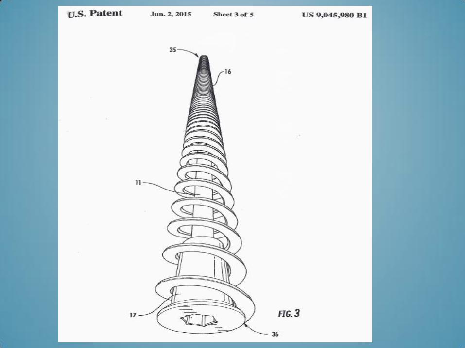
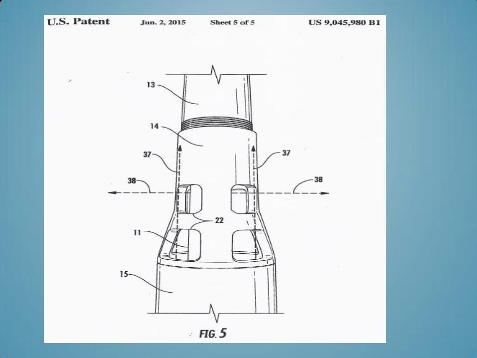
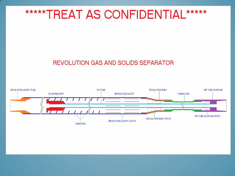
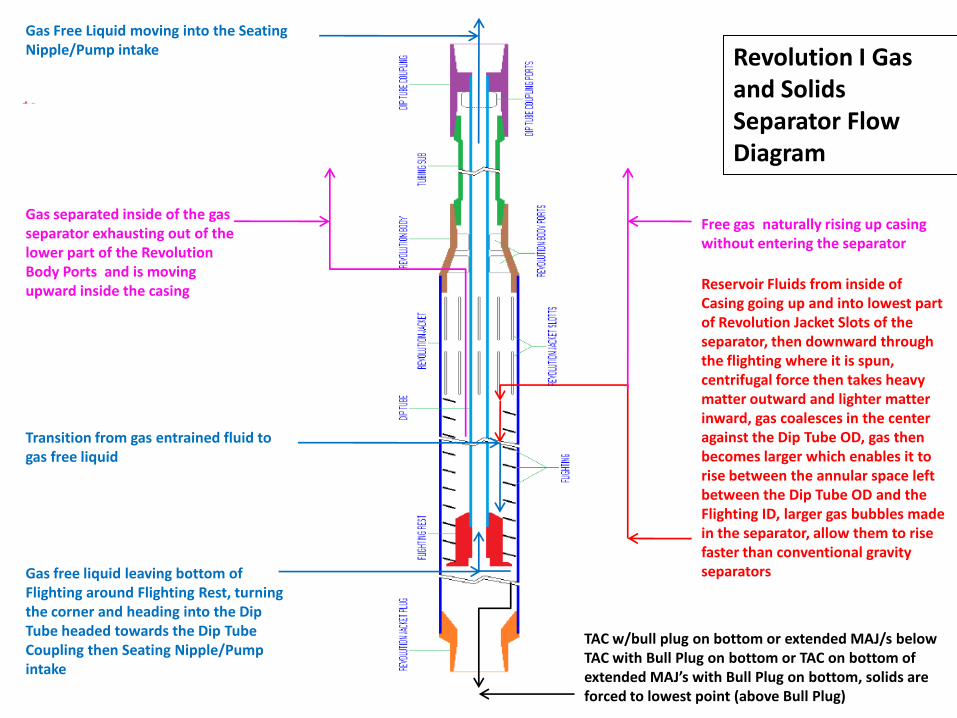
Reservoir Fluids from inside of Casing going up and into lowest part of Revolution Jacket Slots of the separator, then downward through the flighting where it is spun, centrifugal force then takes heavy matter outward and lighter matter inward, gas coalesces in the center against the Dip Tube OD, gas then becomes larger which enables it to rise between the annular space left between the Dip Tube OD and the Flighting ID, larger gas bubbles made in the separator, allow them to rise faster than conventional gravity separators
TAC w/bull plug on bottom or extended MAJ/s below TAC with Bull Plug on bottom or TAC on bottom of extended MAJ’s with Bull Plug on bottom, solids are forced to lowest point (above Bull Plug)
Free gas naturally rising up casing without entering the separator
Transition from gas entrained fluid to gas free liquid
Gas separated inside of the gas separator exhausting out of the lower part of the Revolution Body Ports and is moving upward inside the casing
Gas free liquid leaving bottom of Flighting around Flighting Rest, turning the corner and heading into the Dip Tube headed towards the Dip Tube Coupling then Seating Nipple/Pump intake
Gas Free Liquid moving into the Seating Nipple/Pump intake Revolution I Gas
and Solids Separator Flow Diagram
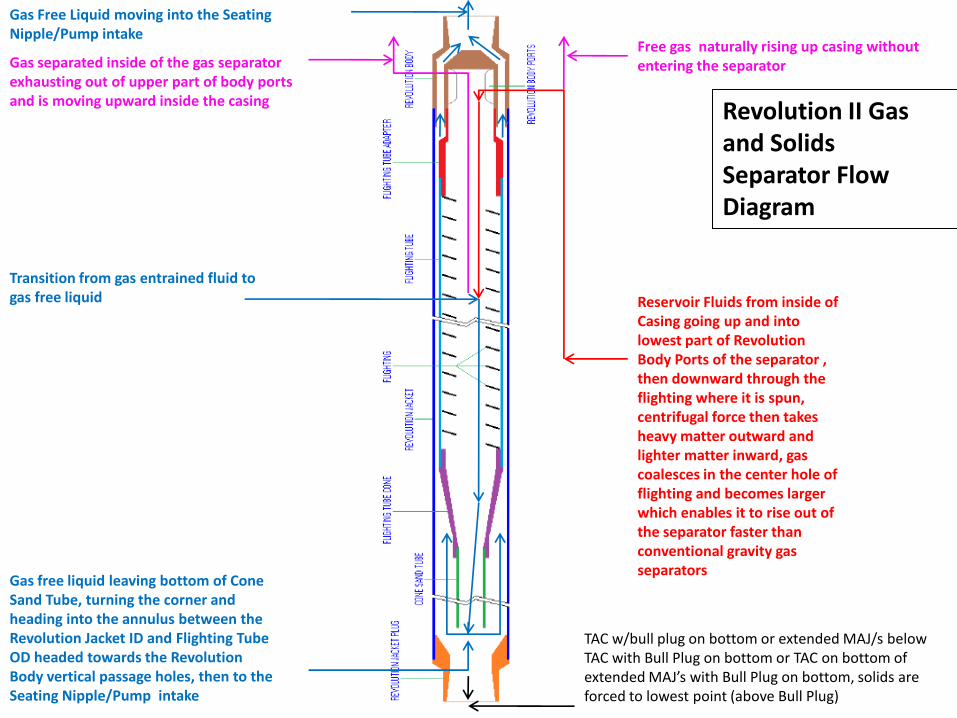
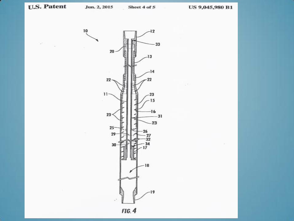
TAC w/bull plug on bottom or extended MAJ/s below TAC with Bull Plug on bottom or TAC on bottom of extended MAJ’s with Bull Plug on bottom, solids are forced to lowest point (above Bull Plug)
Reservoir Fluids from inside of Casing going up and into lowest part of Revolution Body Ports of the separator , then downward through the flighting where it is spun, centrifugal force then takes heavy matter outward and lighter matter inward, gas coalesces in the center hole of flighting and becomes larger which enables it to rise out of the separator faster than conventional gravity gas separators
Free gas naturally rising up casing without entering the separator
Gas Free Liquid moving into the Seating Nipple/Pump intake
Gas separated inside of the gas separator exhausting out of upper part of body ports and is moving upward inside the casing
Gas free liquid leaving bottom of Cone Sand Tube, turning the corner and heading into the annulus between the Revolution Jacket ID and Flighting Tube OD headed towards the Revolution Body vertical passage holes, then to the Seating Nipple/Pump intake
Transition from gas entrained fluid to gas free liquid
Revolution II Gas and Solids Separator Flow Diagram

CML
EXAMPLES

DIFFERENT
COMPANY
- 1ST
OF THREE
EXAMPLES -
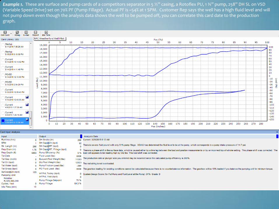
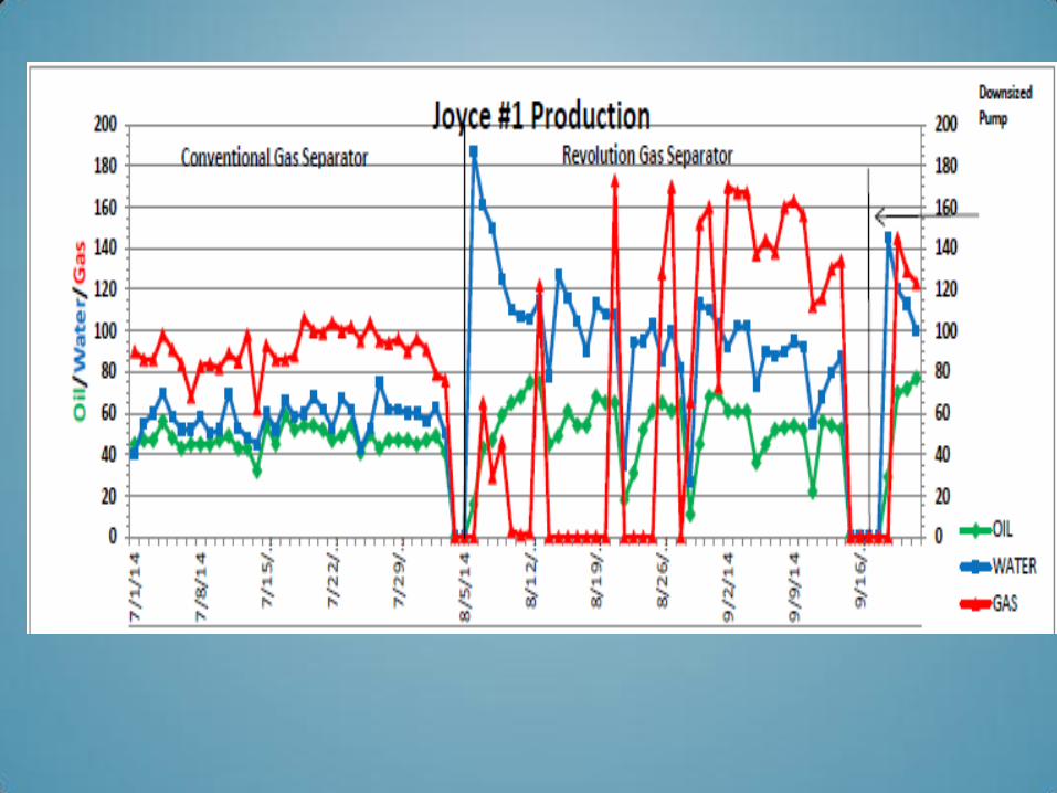
Example 1. These are surface and pump cards of a competitors separator in 5 ½” casing, a Rotoflex PU, 1 ¾” pump, 258” DH SL on VSD (Variable Speed Drive) set on 70% PF (Pump Fillage). Actual PF is ~54% at 1 SPM. Customer Rep says the well has a high fluid level and will not pump down even though the analysis data shows the well to be pumped off, you can correlate this card date to the production graph.
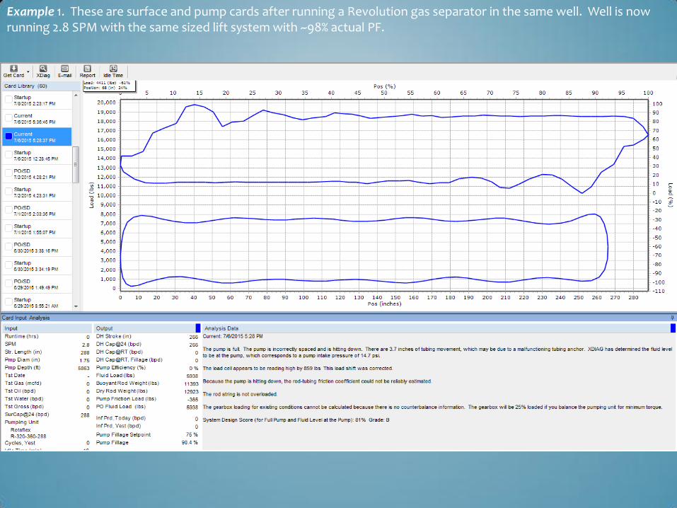
Example 1. These are surface and pump cards after running a Revolution gas separator in the same well. Well is now running 2.8 SPM with the same sized lift system with ~98% actual PF.
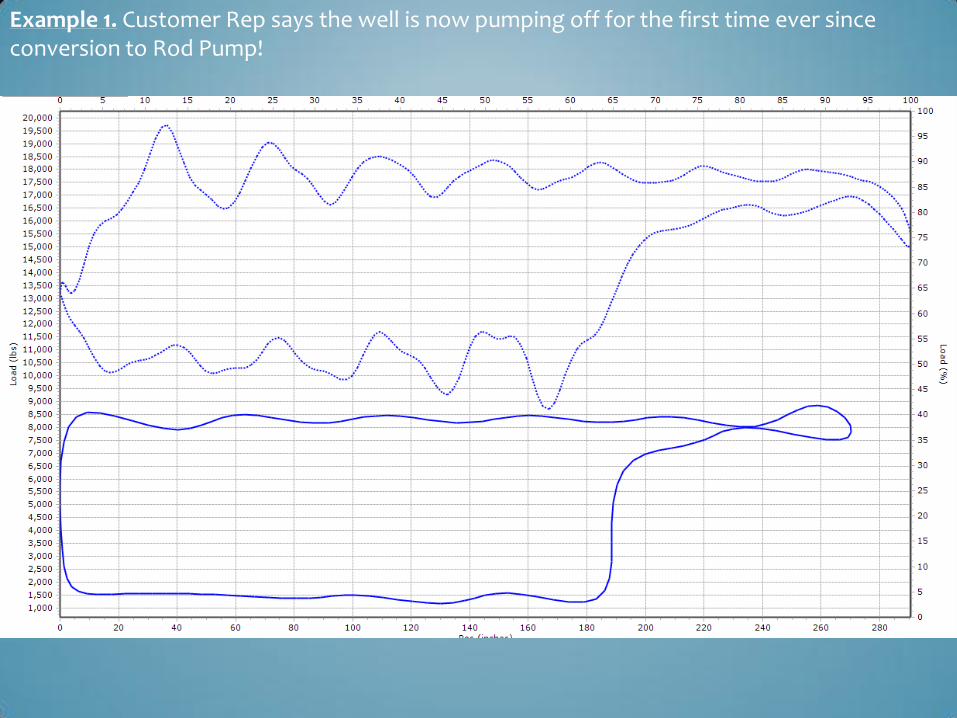
Example 1. Customer Rep says the well is now pumping off for the first time ever since conversion to Rod Pump!
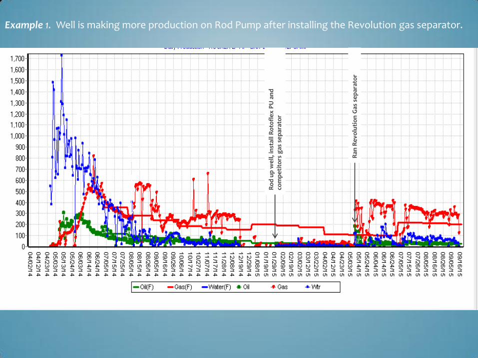
Ran
Re
volu
tio
n G
as s
ep
arat
or
Ro
d u
p w
ell
, in
stal
l Ro
tofl
ex
PU
an
d
com
pe
tito
rs g
as s
ep
arat
or
Example 1. Well is making more production on Rod Pump after installing the Revolution gas separator.
Gas
Lif
t
Flowing

- EXAMPLE 2 -
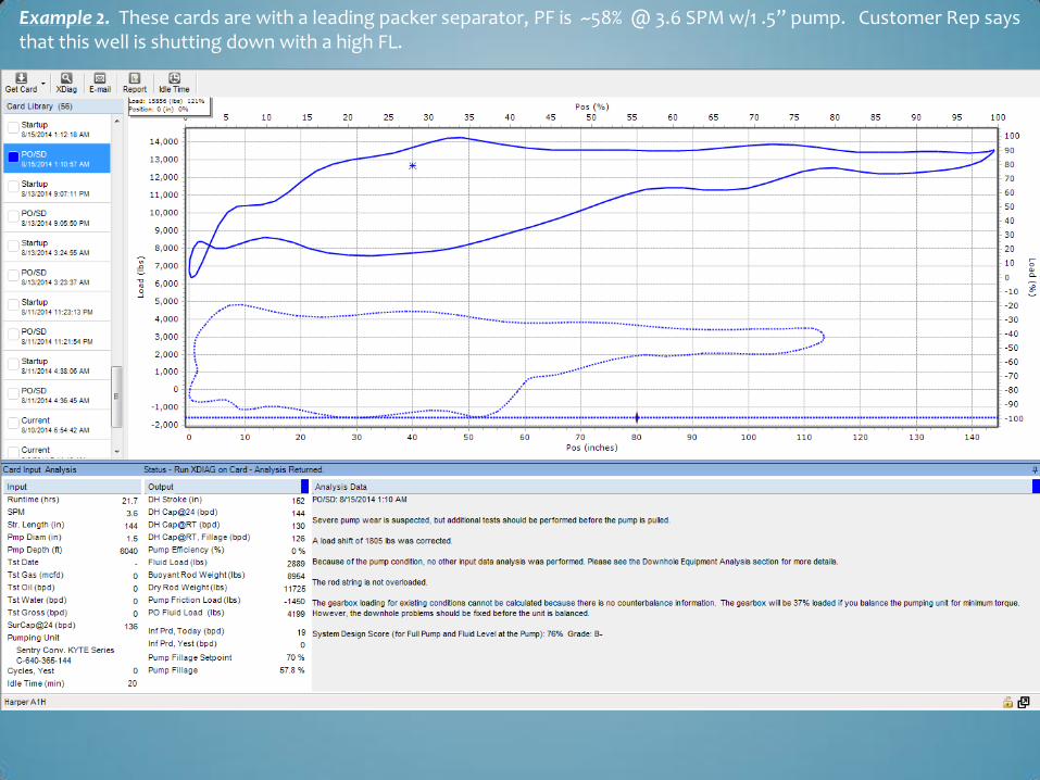
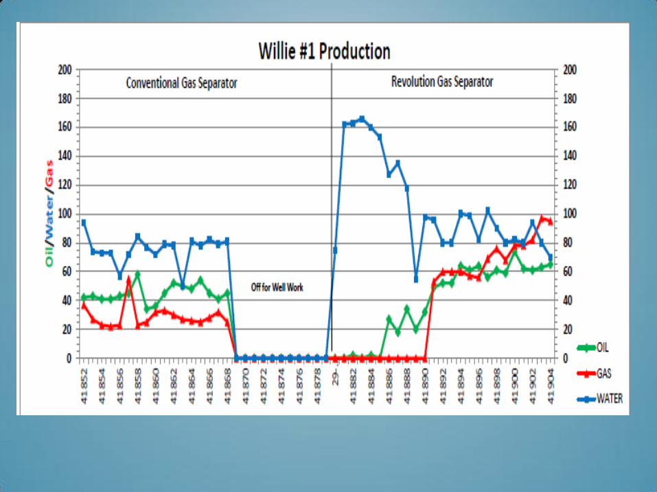
Example 2. These cards are with a leading packer separator, PF is ~58¿ @ 3.6 SPM w/1 .5” pump. Customer Rep says that this well is shutting down with a high FL.
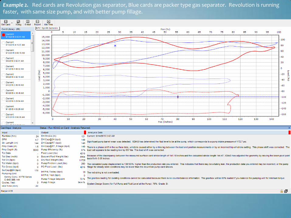
Example 2. Red cards are Revolution gas separator, Blue cards are packer type gas separator. Revolution is running faster, with same size pump, and with better pump fillage.
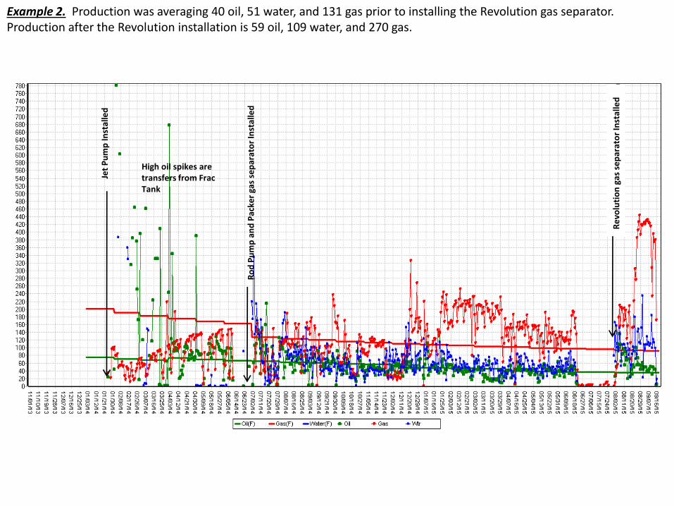
Example 2. Production was averaging 40 oil, 51 water, and 131 gas prior to installing the Revolution gas separator. Production after the Revolution installation is 59 oil, 109 water, and 270 gas.
Jet
Pu
mp
Inst
alle
d
Ro
d P
um
p a
nd
Pac
ker
gas
sep
arat
or
Inst
alle
d
Re
volu
tio
n g
as s
ep
arat
or
Inst
alle
d
High oil spikes are transfers from Frac Tank

- EXAMPLE 3 -
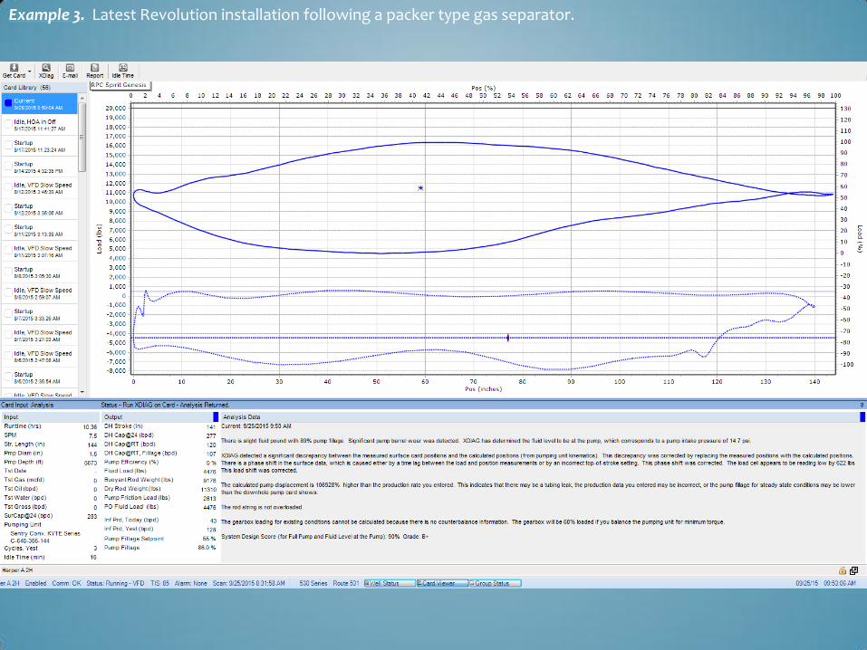
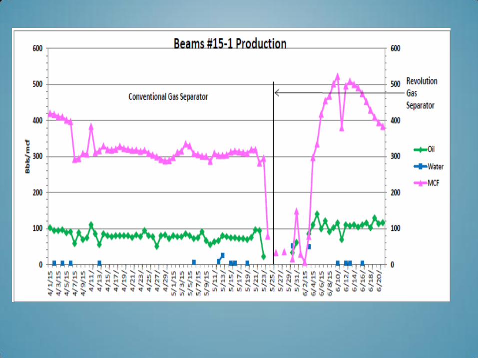
Example 3. Latest Revolution installation following a packer type gas separator.
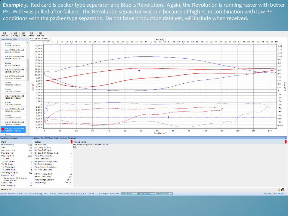
Example 3. Red card is packer type separator and Blue is Revolution. Again, the Revolution is running faster with better PF. Well was pulled after failure. The Revolution separator was run because of high FL in combination with low PF conditions with the packer type separator. Do not have production data yet, will include when received.
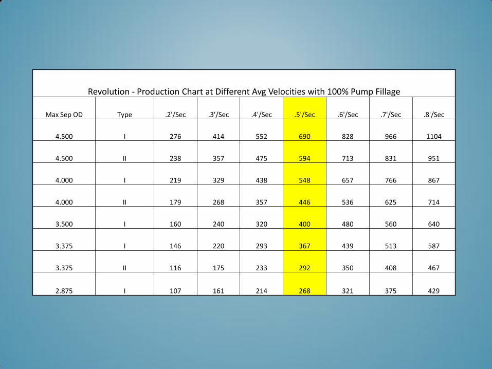
Revolution - Production Chart at Different Avg Velocities with 100% Pump Fillage
Max Sep OD Type .2'/Sec .3'/Sec .4'/Sec .5'/Sec .6'/Sec .7'/Sec .8'/Sec
4.500 I 276 414 552 690 828 966 1104
4.500 II 238 357 475 594 713 831 951
4.000 I 219 329 438 548 657 766 867
4.000 II 179 268 357 446 536 625 714
3.500 I 160 240 320 400 480 560 640
3.375 I 146 220 293 367 439 513 587
3.375 II 116 175 233 292 350 408 467
2.875 I 107 161 214 268 321 375 429
THE REVOLUTION SEPARATOR FLUID HANDING
ABILITY IS RATED WITH THE FLUID TRAVELING .5’
PER SECOND BUT WITH THE CENTRIFUGAL FORCE
GENERATED, THIS BENCHMARK CAN BE EXCEEDED
SOMEWHAT AND STILL GET THE GAS SEPARATION
NEEDED TO EFFICIENTLY PUMP A WELL. IN SOME
OF THE APPLICATIONS, THE CUSTOMER IS
REACHING CLOSE TO OR A LITTLE ABOVE A .6’ PER
SECOND FLUID VELOCITY WHILE STILL
MAINTAINING 97% TO 98% PUMP FILLAGE.
TOOL IS MADE OF 316 STAINLESS STEEL AND BRASS
TO RESIST CORROSION.
ALL COMPONENTS ARE REPARABLE OR
REPLACEABLE.
TOOL CAN BE CLEANED AND REDRESSED IN SHOP.
TOOL IS MADE UP IN SHOP AND WHEN DELIVERED, IT
IS READY TO PICK UP AND INSTALL IN WELL.
NO ADDITIONAL PERSONNEL ON LOCATION.