Embed Size (px)
Citation preview
For free-standing andunderground installation
Grease separatorsmanufactured frompolyethylene
www.kessel.com
2
Grease separators –Everything specialists need to know
Grease separators
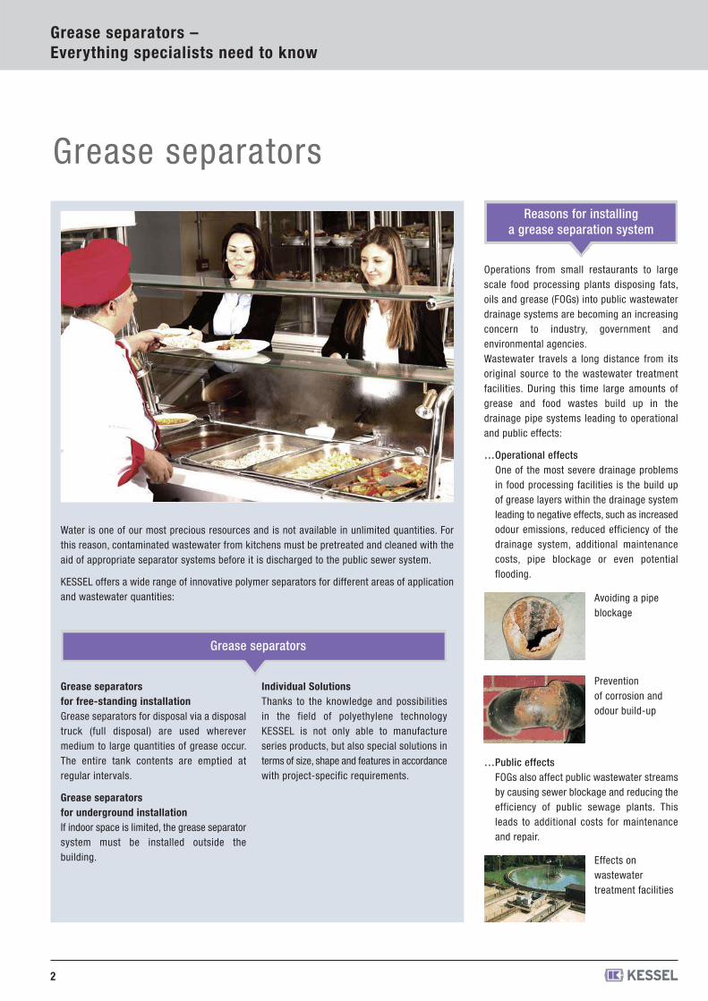
Operations from small restaurants to largescale food processing plants disposing fats,oils and grease (FOGs) into public wastewaterdrainage systems are becoming an increasingconcern to industry, government andenvironmental agencies.Wastewater travels a long distance from itsoriginal source to the wastewater treatmentfacilities. During this time large amounts ofgrease and food wastes build up in thedrainage pipe systems leading to operationaland public effects:
…Operational effectsOne of the most severe drainage problemsin food processing facilities is the build upof grease layers within the drainage systemleading to negative effects, such as increasedodour emissions, reduced efficiency of thedrainage system, additional maintenancecosts, pipe blockage or even potentialflooding.
…Public effectsFOGs also affect public wastewater streamsby causing sewer blockage and reducing theefficiency of public sewage plants. Thisleads to additional costs for maintenanceand repair.
Reasons for installing a grease separation system
Water is one of our most precious resources and is not available in unlimited quantities. Forthis reason, contaminated wastewater from kitchens must be pretreated and cleaned with theaid of appropriate separator systems before it is discharged to the public sewer system.
KESSEL offers a wide range of innovative polymer separators for different areas of applicationand wastewater quantities: Avoiding a pipe
blockage
Prevention of corrosion andodour build-up
Effects on wastewater treatment facilities
Grease separators
Grease separators for free-standing installationGrease separators for disposal via a disposaltruck (full disposal) are used wherevermedium to large quantities of grease occur.The entire tank contents are emptied atregular intervals.
Grease separators for underground installationIf indoor space is limited, the grease separatorsystem must be installed outside thebuilding.
Individual SolutionsThanks to the knowledge and possibilitiesin the field of polyethylene technologyKESSEL is not only able to manufactureseries products, but also special solutions interms of size, shape and features in accordancewith project-specific requirements.
3
For a clean environment
When to use a grease separator ? Separator function based on EN 1825
Grease separators –Everything specialists need to know
…Easy transportTheir low weight allows our greaseseparators to be transported easily by handon site. A special base design also allowsthem to be transported by forklift truck.
…Simple and fast installationWith EasyClean: The curved shape of theone-piece tank makes it ideal for retrofittingpurposes, even where space is tight throughnarrow staircases and doorways for example.
…Fracture resistanceThe polyethylene material ensures a highimpact strength. This means that soilmovements can easily be compensated forwhere installation is in the ground.
…Resistant to aggressive greaseThe polyethylene material used is 100 %resistant to aggressive grease. This guaranteesa long service life since there is no damageto the material due to corrosion.
Polyethylene grease separators –The long term solution
Grease separators should be installed in alllocations where greases and oils from plant oranimal origin are required to be removed fromthe wastewater stream. This applies tocommercial and industrial applications, forexample:
Butchers, meat and sausage factoriesPre-prepared meal productionSlaughterhouses and meat preparationfacilitiesSoap / stearin production plantsRestaurants and fast food shopsFish production facilitiesCooking oil refineries, butter / margarineproductionFrying facilities / nut roasting factoriesCafeterias in commercial buildings, hospitals,universities, military bases and governmentagencies
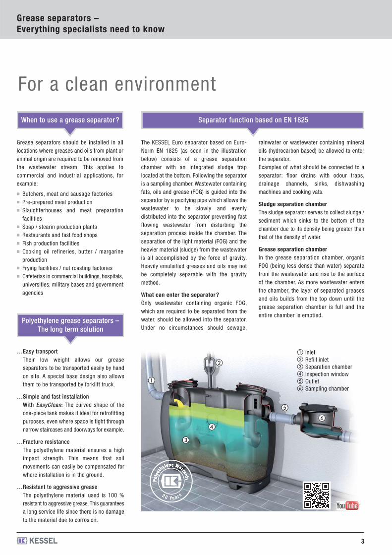
The KESSEL Euro separator based on Euro-Norm EN 1825 (as seen in the illustrationbelow) consists of a grease separationchamber with an integrated sludge traplocated at the bottom. Following the separatoris a sampling chamber. Wastewater containingfats, oils and grease (FOG) is guided into theseparator by a pacifying pipe which allows thewastewater to be slowly and evenlydistributed into the separator preventing fastflowing wastewater from disturbing theseparation process inside the chamber. Theseparation of the light material (FOG) and theheavier material (sludge) from the wastewateris all accomplished by the force of gravity.Heavily emulsified greases and oils may notbe completely separable with the gravitymethod.
What can enter the separator ?Only wastewater containing organic FOG,which are required to be separated from thewater, should be allowed into the separator.Under no circumstances should sewage,
rainwater or wastewater containing mineraloils (hydrocarbon based) be allowed to enterthe separator. Examples of what should be connected to aseparator: floor drains with odour traps,drainage channels, sinks, dishwashingmachines and cooking vats.
Sludge separation chamberThe sludge separator serves to collect sludge /sediment which sinks to the bottom of thechamber due to its density being greater thanthat of the density of water.
Grease separation chamberIn the grease separation chamber, organicFOG (being less dense than water) separatefrom the wastewater and rise to the surfaceof the chamber. As more wastewater entersthe chamber, the layer of separated greasesand oils builds from the top down until thegrease separation chamber is full and theentire chamber is emptied.
①②③④⑤⑥
InletRefill inletSeparation chamberInspection windowOutletSampling chamber
PPoollyy
eett
hhyylleennee WWaarrrraannttyy
2 0 YeY ars

4
Selection criteria
Always the right product –wastewater treatment
G D D+S D+SP M+S PV+SVersion
Products for free standing installation see page 8 / 201018 1214
�
����
���
��
�16
� ���Odour Reduced DisposalThe direct disposal grease separator connection allows thedisposal truck to vacuum out the grease separator contentswithout opening the separator covers.
Control unitThe Shredder-Mix-System, designed to homogenize theseparator contents, can be started and controlled withoutneeding direct access to the separator.
Disposal PumpIn the case that the disposal truck is too high and/or too farfrom the grease separator to allow disposal via the truck'svacuum system, the separator can be equipped its owndisposal pump system.
Odour Free DisposalThe integrated Shredder-Mix-System intakes the entireseparator contents, shreds it and then uses this homogenizedmixture to rinse and clean the interior separator walls.
Fully Automated Operation All of the pre-programmed disposal steps of theseparator's contents function fully automatically.
SELECTION CRITERIA FOR GREASE SEPARATORS
Products for underground installation see page 2627 / 28
INFORMATION
SmartSelect is an efficient tool for configuring, designing and calculating drainage
solutions. It significantly reduces planning effort.
In addition, SmartSelect provides registered users with a project management
program which can be used to request and edit saved projects. Registration at
smartselect.kessel.com is free and takes only a few minutes!
Calculation module lifting stationsCalculation module separatorsConfigurator for alternative sealing in the system
SmartSelect – simply makes planning faster
Do you require more detailed information ?Our Service Centre will be happy to help.
Complete System SolutionIn addition to individual grease- and oilseparators, KESSEL also offers completeseparator packages consisting ofseparator, properly matched lifting stationand advantageous accessories. All fromone source - KESSEL.
Lifting and pumping stations for freestanding and underground installation.Stainless steel drains and channelsfor kitchens and food processing plants.
Individual SolutionsThanks to the knowledge and possibilitiesin the field of polyethylene technologyKESSEL is not only able to manufactureseries products, but also special solutionsin accordance with project-specificrequirements.
ReferencesOver the past decades, KESSEL productshave proven themselves countless times indestinations all over the world. Scan thefollowing QR code to directly view our list ofreferences.
www.kessel.com/references
5
smartselect.kessel.com
6
KESSEL-Product informationPolyethylene grease separators
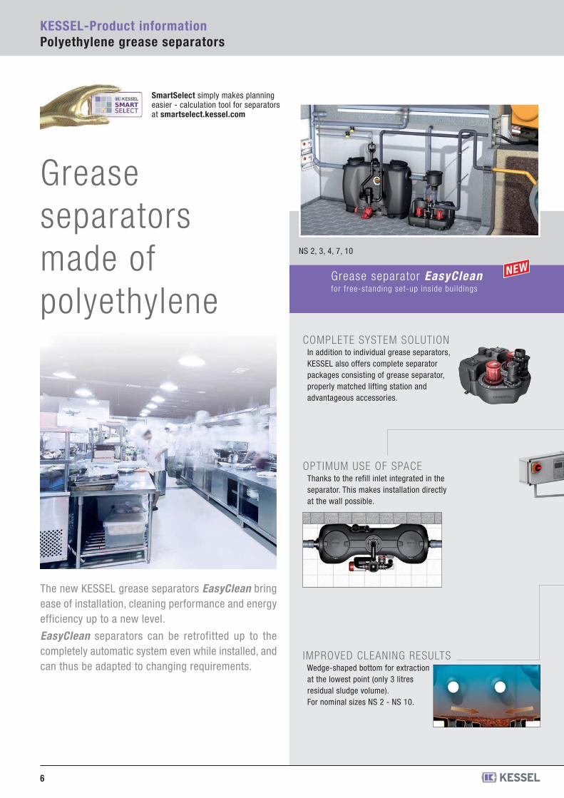
The new KESSEL grease separators EasyClean bringease of installation, cleaning performance and energyefficiency up to a new level.
EasyClean separators can be retrofitted up to thecompletely automatic system even while installed, andcan thus be adapted to changing requirements.
NS 2, 3, 4, 7, 10
Grease separator EasyCleanfor free-standing set-up inside bui ldings
SmartSelect simply makes planning easier - calculation tool for separatorsat smartselect.kessel.com
COMPLETE SYSTEM SOLUTIONIn addition to individual grease separators,KESSEL also offers complete separatorpackages consisting of grease separator,properly matched lifting station andadvantageous accessories.
OPTIMUM USE OF SPACE Thanks to the refill inlet integrated in theseparator. This makes installation directlyat the wall possible.
IMPROVED CLEANING RESULTS Wedge-shaped bottom for extractionat the lowest point (only 3 litresresidual sludge volume).For nominal sizes NS 2 - NS 10.
Grease separators made of polyethylene
7
Grease separator Euroaccording to EN 1825 and DIN 4040-100
NS 15 - NS 25 NS 1 - NS 35
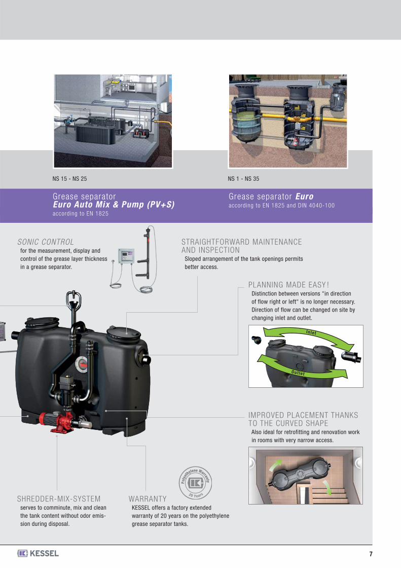
Grease separatorEuro Auto Mix & Pump (PV+S)according to EN 1825
SHREDDER-MIX-SYSTEMserves to comminute, mix and cleanthe tank content without odor emis-sion during disposal.
SONIC CONTROLfor the measurement, display andcontrol of the grease layer thicknessin a grease separator.
STRAIGHTFORWARD MAINTENANCEAND INSPECTION
Sloped arrangement of the tank openings permitsbetter access.
PLANNING MADE EASY ! Distinction between versions "in directionof flow right or left" is no longer necessary.Direction of flow can be changed on site bychanging inlet and outlet.
In let
Out let
WARRANTYKESSEL offers a factory extendedwarranty of 20 years on the polyethylenegrease separator tanks.
IMPROVED PLACEMENT THANKSTO THE CURVED SHAPE
Also ideal for retrofitting and renovation workin rooms with very narrow access.
Poly
et
hylene Warranty Poly
et
hylene Warranty
20 Years
93 002.01/PVS93 003.01/PVS93 004.01/PVS93 007.01/PVS93 010.01/PVS
without SonicControlNS 2NS 3NS 4NS 7NS 10
160 kg165 kg178 kg226 kg272 kg
93 002.02/PVS93 003.02/PVS93 004.02/PVS93 007.02/PVS93 010.02/PVS
with SonicControlNS 2NS 3NS 4NS 7NS 10
160 kg165 kg178 kg226 kg272 kg
Article description Weight Article #NS
8
Illustration
Certification: Z-54.1-474
Delivery:System completely assembled.
Accessories: Sampling chamber, lifting stations, remote control, TeleControl
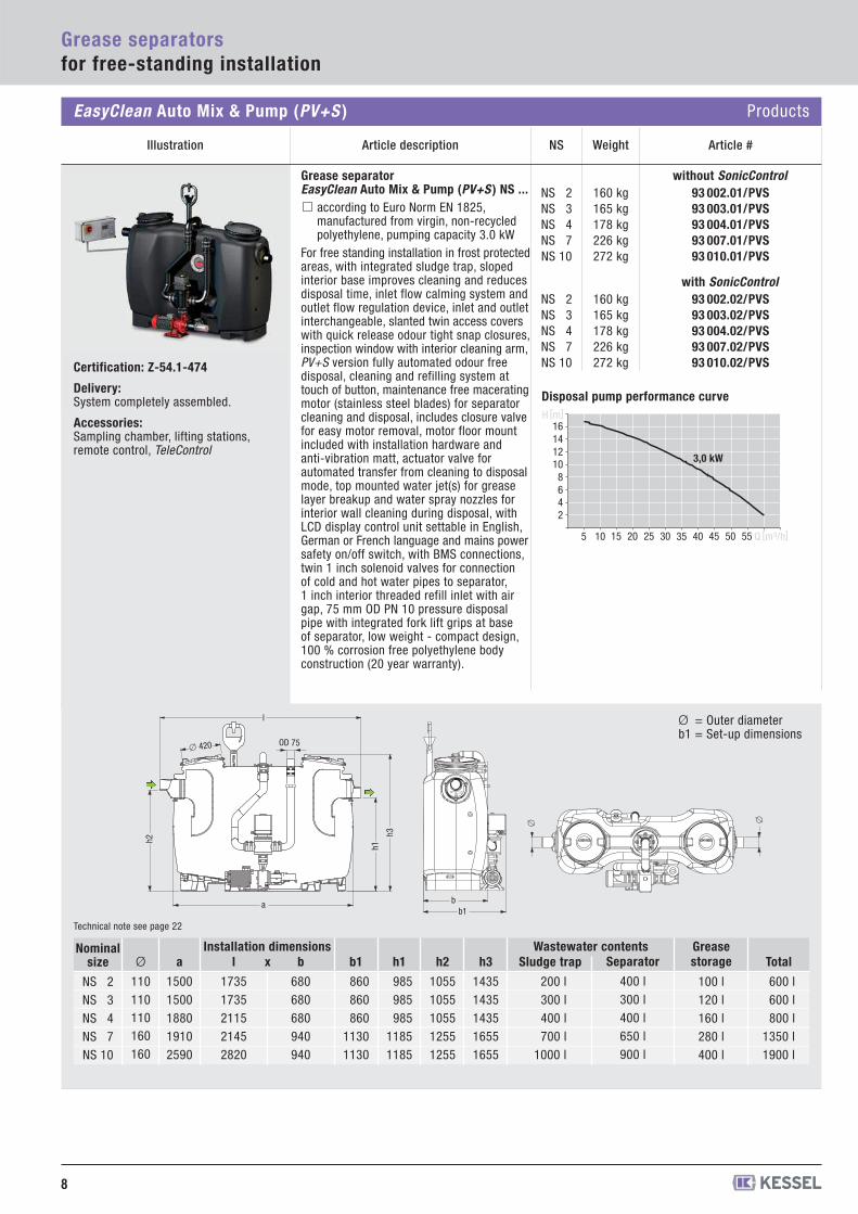
Grease separator EasyClean Auto Mix & Pump (PV+S ) NS ...
according to Euro Norm EN 1825,manufactured from virgin, non-recycledpolyethylene, pumping capacity 3.0 kW
For free standing installation in frost protectedareas, with integrated sludge trap, slopedinterior base improves cleaning and reducesdisposal time, inlet flow calming system andoutlet flow regulation device, inlet and outletinterchangeable, slanted twin access coverswith quick release odour tight snap closures,inspection window with interior cleaning arm,PV+S version fully automated odour freedisposal, cleaning and refilling system attouch of button, maintenance free maceratingmotor (stainless steel blades) for separatorcleaning and disposal, includes closure valvefor easy motor removal, motor floor mountincluded with installation hardware andanti-vibration matt, actuator valve forautomated transfer from cleaning to disposalmode, top mounted water jet(s) for greaselayer breakup and water spray nozzles forinterior wall cleaning during disposal, withLCD display control unit settable in English,German or French language and mains powersafety on/off switch, with BMS connections,twin 1 inch solenoid valves for connectionof cold and hot water pipes to separator,1 inch interior threaded refill inlet with airgap, 75 mm OD PN 10 pressure disposalpipe with integrated fork lift grips at baseof separator, low weight - compact design,100 % corrosion free polyethylene bodyconstruction (20 year warranty).
2468
10121416
10 20 30 405 15 25 35 5045 55
3,0 kW
H [m]
Q [m3/h]
Grease separatorsfor free-standing installation
EasyClean Auto Mix & Pump (PV+S ) Products
Ø = Outer diameter b1 = Set-up dimensions
b1 b
�
�
Technical note see page 22
1)
Ø
110110110160160
a
15001500188019102590
b
680680680940940
h1
985985985
11851185
h2
10551055105512551255
h3
14351435143516551655
l
17351735211521452820
Sludge trap
200 l300 l400 l700 l
1000 l
Wastewater contentsSeparator
400 l300 l400 l650 l900 l
Grease storage
100 l120 l160 l280 l400 l
Nominalsize
NS 2NS 3NS 4NS 7NS 10
b1
860860860
11301130
xInstallation dimensions
Total
600 l600 l800 l
1350 l1900 l
H [m] = Backwater height
h2
a
l
h1
h3
� 420 OD 75
Disposal pump performance curve
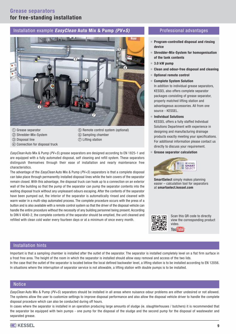
Installation example EasyClean Auto Mix & Pump (PV+S) Professional advantages
Program-controlled disposal and rinsingdevice
Shredder-Mix-System for homogenisationof the tank contents
3.0 kW pump
Clean and odour-free disposal and cleaning
Optional remote control
Complete System SolutionIn addition to individual grease separators,KESSEL also offers complete separatorpackages consisting of grease separator,properly matched lifting station andadvantageous accessories. All from onesource - KESSEL.
Individual SolutionsKESSEL offers a fully staffed IndividualSolutions Department with experience indesigning and manufacturing drainageproducts exactly meeting your specifications.For additional information please contact usdirectly to discuss your requirement.
Grease separator calculation
9
Grease separatorsfor free-standing installation
Installation hints
Important is that a sampling chamber is installed after the outlet of the separator. The separator is installed completely level on a flat firm surface ina frost free area. The height of the room in which the separator is installed should allow easy removal and access of the two lids.In the case that the outlet of the separator is located below the local defined backwater level, a lifting station is to be installed according to EN 12056.In situations where the interruption of separator service is not allowable, a lifting station with double pumps is to be installed.
Notice
EasyClean Auto Mix & Pump (PV+S ) separators should be installed in all areas where nuisance odour problems are either undesired or not allowed.The systems allow the user to customize settings to improve disposal performance and also allow the disposal vehicle driver to handle the completedisposal procedure which can also be conducted during off hours. In cases where the separator is installed in an operation producing large amounts of sludge (ie. slaughterhouses / butchers) it is recommended thatthe separator be equipped with twin pumps - one pump for the disposal of the sludge and the second pump for the disposal of wastewater andseparated grease.
EasyClean Auto Mix & Pump (PV+S ) grease separators are designed according to EN 1825-1 andare equipped with a fully automated disposal, self cleaning and refill system. These separatorsdistinguish themselves through their ease of installation and nearly maintenance freecharacteristics.The advantage of the EasyClean Auto Mix & Pump (PV+S ) separators is that a complete disposalcan take place through permanently installed disposal lines while the twin covers of the separatorremain closed. With this advantage, the disposal truck can hook up to a connection on an exteriorwall of the building so that the pump of the separator can pump the separator contents into thewaiting disposal truck without any unpleasant odours escaping. After the contents of the separatorhave been pumped out, the interior of the separator is automatically rinsed and cleaned withwarm water in a multi-step automated process. The complete procedure occurs with the press of abutton and is also available with a remote control system so that the driver of the disposal vehicle canhandle the entire procedure without the necessity of any building personnel being present. Accordingto DIN V 4040-2, the complete contents of the separator should be emptied, the unit cleaned andrefilled with clean cold water every fourteen days or at a minimum of once every month.
� �
Scan this QR code to directly view the corresponding product video.
SmartSelect simply makes planning easier – calculation tool for separators at smartselect.kessel.com
�
�
�
�
�
① Grease separator② Shredder-Mix-System ③ Disposal line ④ Connection for disposal truck
⑤ Remote control system (optional)⑥ Sampling chamber⑦ Lifting station
93 002.01/MS93 003.01/MS93 004.01/MS93 007.01/MS93 010.01/MS
without SonicControlNS 2NS 3NS 4NS 7NS 10
155 kg160 kg173 kg221 kg267 kg
93 002.02/MS93 003.02/MS93 004.02/MS93 007.02/MS93 010.02/MS
with SonicControlNS 2NS 3NS 4NS 7NS 10
155 kg160 kg173 kg221 kg267 kg
Weight Article #NS
10
Grease separatorsfor free-standing installation
Illustration Article description
Certification: Z-54.1-474
Delivery:System completely assembled.
Accessories: Sampling chamber, lifting stations, TeleControl
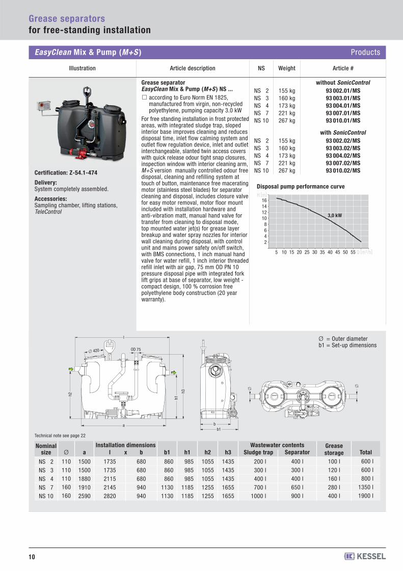
Grease separator EasyClean Mix & Pump (M+S ) NS ...
according to Euro Norm EN 1825,manufactured from virgin, non-recycledpolyethylene, pumping capacity 3.0 kW
For free standing installation in frost protectedareas, with integrated sludge trap, slopedinterior base improves cleaning and reducesdisposal time, inlet flow calming system andoutlet flow regulation device, inlet and outletinterchangeable, slanted twin access coverswith quick release odour tight snap closures,inspection window with interior cleaning arm,M+S version manually controlled odour freedisposal, cleaning and refilling system attouch of button, maintenance free maceratingmotor (stainless steel blades) for separatorcleaning and disposal, includes closure valvefor easy motor removal, motor floor mountincluded with installation hardware andanti-vibration matt, manual hand valve fortransfer from cleaning to disposal mode,top mounted water jet(s) for grease layerbreakup and water spray nozzles for interiorwall cleaning during disposal, with controlunit and mains power safety on/off switch,with BMS connections, 1 inch manual handvalve for water refill, 1 inch interior threadedrefill inlet with air gap, 75 mm OD PN 10pressure disposal pipe with integrated forklift grips at base of separator, low weight -compact design, 100 % corrosion freepolyethylene body construction (20 yearwarranty).
2468
10121416
10 20 30 405 15 25 35 5045 55
3,0 kW
H [m]
Q [m3/h]
EasyClean Mix & Pump (M+S ) Products
Ø = Outer diameter b1 = Set-up dimensions
b1 b
h2
a
l
h1
h3
� 420 OD 75
�
�
Technical note see page 22
1)
Ø
110110110160160
a
15001500188019102590
b
680680680940940
h1
985985985
11851185
h2
10551055105512551255
h3
14351435143516551655
l
17351735211521452820
Sludge trap
200 l300 l400 l700 l
1000 l
Wastewater contentsSeparator
400 l300 l400 l650 l900 l
Grease storage
100 l120 l160 l280 l400 l
Nominalsize
NS 2NS 3NS 4NS 7NS 10
b1
860860860
11301130
xInstallation dimensions
Total600 l600 l800 l
1350 l1900 l
H [m] = Backwater height
Disposal pump performance curve

Installation example EasyClean Mix & Pump (M+S ) Professional advantages
EasyClean Mix & Pump (M+S ) grease separators are designed according to EN 1825-1 and areequipped with an automated self-cleaning system as well as a pumping disposal system. Theseseparators distinguish themselves through their ease of installation and nearly maintenance freecharacteristics.The advantage of the EasyClean Mix & Pump (M+S ) separators is that disposal can take placethrough permanently installed disposal lines while the twin covers of the separator remain closed.With this advantage, the disposal truck can hook up to a connection on an exterior wall of thebuilding so that the pump of the separator can pump the separator contents into the waitingdisposal truck without any unpleasant odours escaping. After the contents of the separator havebeen pumped out, the interior of the separator is automatically rinsed and cleaned with warmwater in a multi-step process which is manually controlled from the control unit. According toDIN V 4040-2, the complete contents of the separator should be emptied, the unit cleaned andrefilled with clean cold water every fourteen days or at a minimum of once every month.
Manual disposal and rinsing device
Shredder-Mix-System for homogenisationof the tank contents
3.0 kW pump
Clean and odour-free disposal and cleaning
11
Grease separatorsfor free-standing installation
Installation hints
Important is that a sampling chamber is installed after the outlet of the separator. The separator is installed completely level on a flat firm surface ina frost free area. The height of the room in which the separator is installed should allow easy removal and access of the two lids.In the case that the outlet of the separator is located below the local defined backwater level, a lifting station is to be installed according to EN 12056.In situations where the interruption of separator service is not allowable, a lifting station with double pumps is to be installed.
Notice
EasyClean Mix & Pump (M+S ) separators should be installed in all areas where nuisance odour problems are either undesired or not allowed. In caseswhere the separator is installed in an operation producing large amounts of sludge (ie. slaughterhouses / butchers) it is recommended that the separatorbe equipped with twin pumps - one pump for the disposal of the sludge and the second pump for the disposal of wastewater and separated grease.
Scan this QR code to directly view the corresponding product video.
�
Simple control
Complete System SolutionIn addition to individual grease separators,KESSEL also offers complete separatorpackages consisting of grease separator,properly matched lifting station andadvantageous accessories. All from onesource - KESSEL.
Individual SolutionsKESSEL offers a fully staffed IndividualSolutions Department with experience indesigning and manufacturing drainageproducts exactly meeting your specifications.For additional information please contact usdirectly to discuss your requirement.
SmartSelect simply makes planning easier – calculation tool for separators at smartselect.kessel.com
Grease separator calculation
�
��
�
�
�
① Grease separator② Shredder-Mix-System ③ Disposal line ④ Connection for disposal truck
⑤ Control unit⑥ Sampling chamber⑦ Lifting station
12
Grease separatorsfor free-standing installation
EasyClean Auto Mix (D+SP ) Products
Weight Article #NSIllustration Article description
93 002.01/DSP93 003.01/DSP93 004.01/DSP93 007.01/DSP93 010.01/DSP
without SonicControlNS 2NS 3NS 4NS 7NS 10
150 kg155 kg168 kg216 kg262 kg
93 002.02/DSP93 003.02/DSP93 004.02/DSP93 007.02/DSP93 010.02/DSP
with SonicControlNS 2NS 3NS 4NS 7NS 10
150 kg155 kg168 kg216 kg262 kgCertification: Z-54.1-474
Delivery:System completely assembled.
Accessories: Sampling chamber, lifting stations, remote control, TeleControl
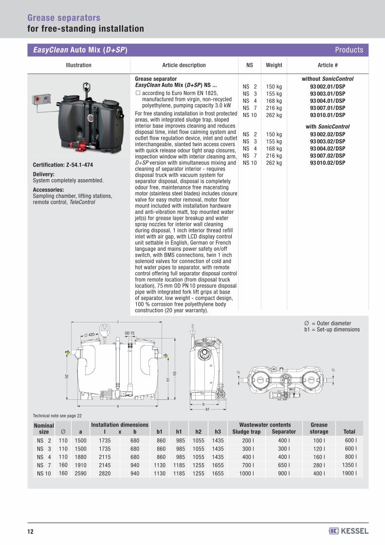
Ø = Outer diameter b1 = Set-up dimensions
Grease separator EasyClean Auto Mix (D+SP ) NS ...
according to Euro Norm EN 1825,manufactured from virgin, non-recycledpolyethylene, pumping capacity 3.0 kW
For free standing installation in frost protectedareas, with integrated sludge trap, slopedinterior base improves cleaning and reducesdisposal time, inlet flow calming system andoutlet flow regulation device, inlet and outletinterchangeable, slanted twin access coverswith quick release odour tight snap closures,inspection window with interior cleaning arm,D+SP version with simultaneous mixing andcleaning of separator interior - requiresdisposal truck with vacuum system forseparator disposal, disposal is completelyodour free, maintenance free maceratingmotor (stainless steel blades) includes closurevalve for easy motor removal, motor floormount included with installation hardwareand anti-vibration matt, top mounted waterjet(s) for grease layer breakup and waterspray nozzles for interior wall cleaningduring disposal, 1 inch interior thread refillinlet with air gap, with LCD display controlunit settable in English, German or Frenchlanguage and mains power safety on/offswitch, with BMS connections, twin 1 inchsolenoid valves for connection of cold andhot water pipes to separator, with remotecontrol offering full separator disposal controlfrom remote location (from disposal trucklocation), 75 mm OD PN 10 pressure disposalpipe with integrated fork lift grips at baseof separator, low weight - compact design,100 % corrosion free polyethylene bodyconstruction (20 year warranty).
h2
a
l
h1
h3
� 420 OD 75
b1 b
�
�
Technical note see page 22
1)
Ø
110110110160160
a
15001500188019102590
b
680680680940940
h1
985985985
11851185
h2
10551055105512551255
h3
14351435143516551655
l
17351735211521452820
Sludge trap
200 l300 l400 l700 l
1000 l
Wastewater contentsSeparator
400 l300 l400 l650 l900 l
Grease storage
100 l120 l160 l280 l400 l
Nominalsize
NS 2NS 3NS 4NS 7NS 10
b1
860860860
11301130
xInstallation dimensions
Total600 l600 l800 l
1350 l1900 l
13
Grease separatorsfor free-standing installation
Installation example EasyClean Auto Mix (D+SP ) Professional advantages
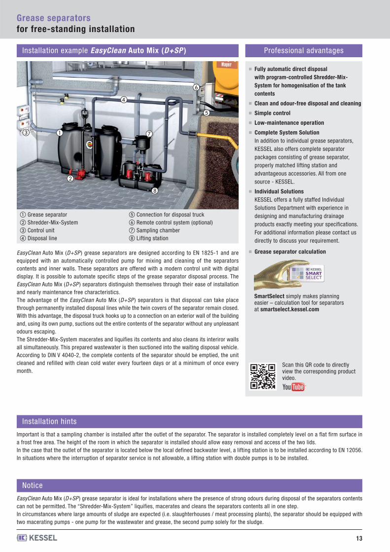
EasyClean Auto Mix (D+SP ) grease separators are designed according to EN 1825-1 and areequipped with an automatically controlled pump for mixing and cleaning of the separatorscontents and inner walls. These separators are offered with a modern control unit with digitaldisplay. It is possible to automate specific steps of the grease separator disposal process. TheEasyClean Auto Mix (D+SP ) separators distinguish themselves through their ease of installationand nearly maintenance free characteristics.The advantage of the EasyClean Auto Mix (D+SP ) separators is that disposal can take placethrough permanently installed disposal lines while the twin covers of the separator remain closed.With this advantage, the disposal truck hooks up to a connection on an exterior wall of the buildingand, using its own pump, suctions out the entire contents of the separator without any unpleasantodours escaping.The Shredder-Mix-System macerates and liquifies its contents and also cleans its interiror wallsall simultaneously. This prepared wastewater is then suctioned into the waiting disposal vehicle.According to DIN V 4040-2, the complete contents of the separator should be emptied, the unitcleaned and refilled with clean cold water every fourteen days or at a minimum of once everymonth.
Fully automatic direct disposalwith program-controlled Shredder-Mix-System for homogenisation of the tankcontents
Clean and odour-free disposal and cleaning
Simple control
Low-maintenance operation
Installation hints
Important is that a sampling chamber is installed after the outlet of the separator. The separator is installed completely level on a flat firm surface ina frost free area. The height of the room in which the separator is installed should allow easy removal and access of the two lids.In the case that the outlet of the separator is located below the local defined backwater level, a lifting station is to be installed according to EN 12056.In situations where the interruption of separator service is not allowable, a lifting station with double pumps is to be installed.
Notice
EasyClean Auto Mix (D+SP ) grease separator is ideal for installations where the presence of strong odours during disposal of the separators contentscan not be permitted. The “Shredder-Mix-System” liquifies, macerates and cleans the separators contents all in one step.In circumstances where large amounts of sludge are expected (i.e. slaughterhouses / meat processing plants), the separator should be equipped withtwo macerating pumps - one pump for the wastewater and grease, the second pump solely for the sludge.
Scan this QR code to directly view the corresponding product video.
� Complete System SolutionIn addition to individual grease separators,KESSEL also offers complete separatorpackages consisting of grease separator,properly matched lifting station andadvantageous accessories. All from onesource - KESSEL.
Individual SolutionsKESSEL offers a fully staffed IndividualSolutions Department with experience indesigning and manufacturing drainageproducts exactly meeting your specifications.For additional information please contact usdirectly to discuss your requirement.
Grease separator calculation
SmartSelect simply makes planning easier – calculation tool for separators at smartselect.kessel.com
�
�
�
�
① Grease separator② Shredder-Mix-System ③ Control unit ④ Disposal line
⑤ Connection for disposal truck ⑥ Remote control system (optional)⑦ Sampling chamber⑧ Lifting station
�
�
Weight Article #NSArticle descriptionIllustration
14
NS 2NS 3NS 4NS 7NS 10
145 kg150 kg163 kg211 kg257 kg
NS 2NS 3NS 4NS 7NS 10
145 kg150 kg163 kg211 kg257 kg
Certification: Z-54.1-474
Delivery:System completely assembled.
Accessories: Sampling chamber, lifting stations
Illustration shows Art. # 93 004.31/DS
Ø = Outer diameter b1 = Set-up dimensions
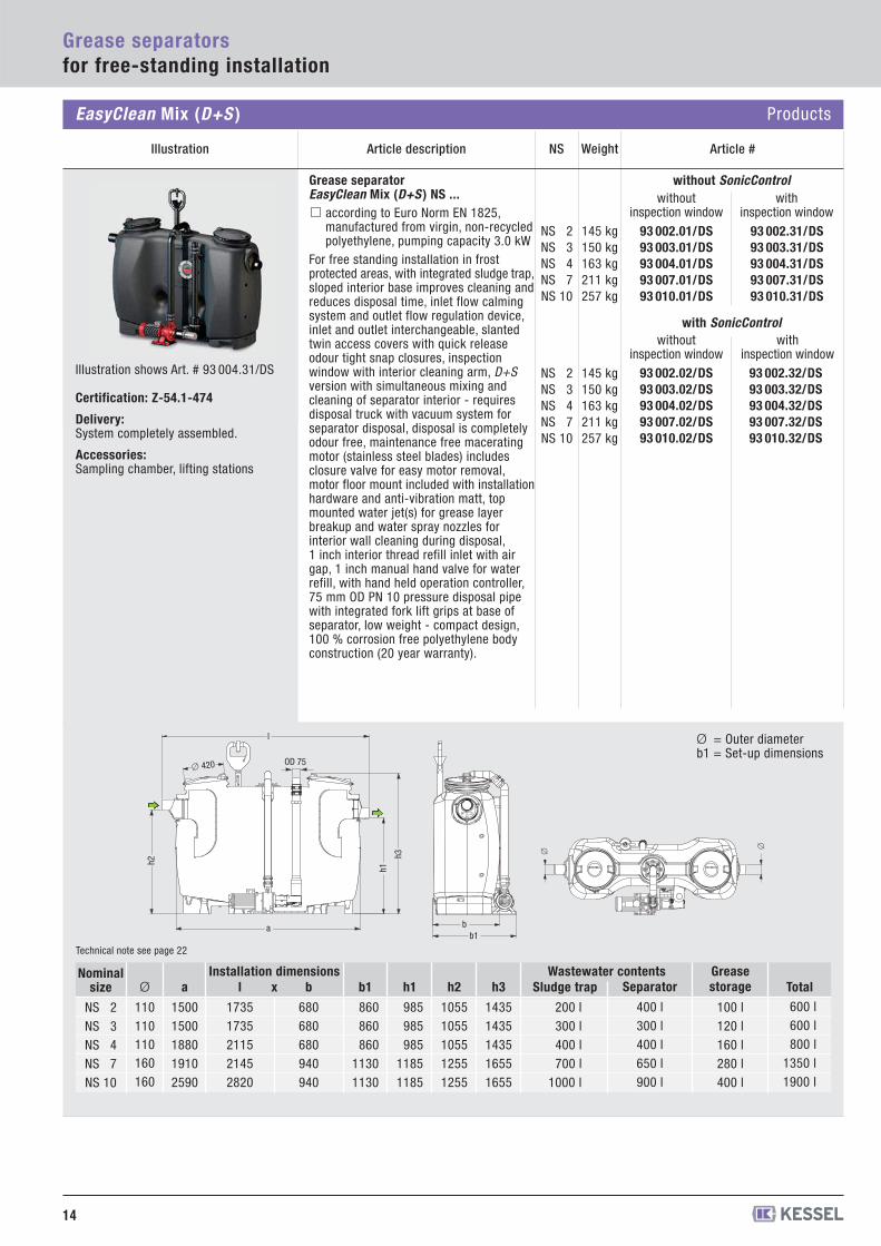
Grease separator EasyClean Mix (D+S ) NS ...
according to Euro Norm EN 1825,manufactured from virgin, non-recycledpolyethylene, pumping capacity 3.0 kW
For free standing installation in frostprotected areas, with integrated sludge trap,sloped interior base improves cleaning andreduces disposal time, inlet flow calmingsystem and outlet flow regulation device,inlet and outlet interchangeable, slantedtwin access covers with quick releaseodour tight snap closures, inspectionwindow with interior cleaning arm, D+Sversion with simultaneous mixing andcleaning of separator interior - requiresdisposal truck with vacuum system forseparator disposal, disposal is completelyodour free, maintenance free maceratingmotor (stainless steel blades) includesclosure valve for easy motor removal,motor floor mount included with installationhardware and anti-vibration matt, topmounted water jet(s) for grease layerbreakup and water spray nozzles forinterior wall cleaning during disposal,1 inch interior thread refill inlet with airgap, 1 inch manual hand valve for waterrefill, with hand held operation controller,75 mm OD PN 10 pressure disposal pipewith integrated fork lift grips at base ofseparator, low weight - compact design,100 % corrosion free polyethylene bodyconstruction (20 year warranty).
h2
a
l
h1
h3
� 420 OD 75
b1 b
�
�
Technical note see page 22
Grease separatorsfor free-standing installation
EasyClean Mix (D+S ) Products
93 002.01/DS93 003.01/DS93 004.01/DS93 007.01/DS93 010.01/DS
93 002.31/DS93 003.31/DS93 004.31/DS93 007.31/DS93 010.31/DS
without SonicControlwithout
inspection windowwith
inspection window
93 002.02/DS93 003.02/DS93 004.02/DS93 007.02/DS93 010.02/DS
93 002.32/DS93 003.32/DS93 004.32/DS93 007.32/DS93 010.32/DS
with SonicControlwithout
inspection windowwith
inspection window
1)
Ø
110110110160160
a
15001500188019102590
b
680680680940940
h1
985985985
11851185
h2
10551055105512551255
h3
14351435143516551655
l
17351735211521452820
Sludge trap
200 l300 l400 l700 l
1000 l
Wastewater contentsSeparator
400 l300 l400 l650 l900 l
Grease storage
100 l120 l160 l280 l400 l
Nominalsize
NS 2NS 3NS 4NS 7NS 10
b1
860860860
11301130
xInstallation dimensions
Total600 l600 l800 l
1350 l1900 l
15
Grease separatorsfor free-standing installation
Installation example EasyClean Mix (D+S ) Professional advantages
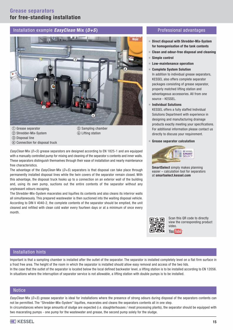
EasyClean Mix (D+S ) grease separators are designed according to EN 1825-1 and are equippedwith a manually controlled pump for mixing and cleaning of the separator s contents and inner walls.These separators distinguish themselves through their ease of installation and nearly maintenancefree characteristics. The advantage of the EasyClean Mix (D+S ) separators is that disposal can take place throughpermanently installed disposal lines while the twin covers of the separator remain closed. Withthis advantage, the disposal truck hooks up to a connection on an exterior wall of the buildingand, using its own pump, suctions out the entire contents of the separator without anyunpleasant odours escaping.The Shredder-Mix-System macerates and liquifies its contents and also cleans its interiror wallsall simultaneously. This prepared wastewater is then suctioned into the waiting disposal vehicle.According to DIN V 4040-2, the complete contents of the separator should be emptied, the unitcleaned and refilled with clean cold water every fourteen days or at a minimum of once everymonth.
Direct disposal with Shredder-Mix-Systemfor homogenisation of the tank contents
Clean and odour-free disposal and cleaning
Simple control
Low-maintenance operation
Installation hints
Important is that a sampling chamber is installed after the outlet of the separator. The separator is installed completely level on a flat firm surface ina frost free area. The height of the room in which the separator is installed should allow easy removal and access of the two lids.In the case that the outlet of the separator is located below the local defined backwater level, a lifting station is to be installed according to EN 12056.In situations where the interruption of separator service is not allowable, a lifting station with double pumps is to be installed.
Notice
EasyClean Mix (D+S ) grease separator is ideal for installations where the presence of strong odours during disposal of the separators contents cannot be permitted. The “Shredder-Mix-System” liquifies, macerates and cleans the separators contents all in one step.In circumstances where large amounts of sludge are expected (i.e. slaughterhouses / meat processing plants), the separator should be equipped withtwo macerating pumps - one pump for the wastewater and grease, the second pump solely for the sludge.
Scan this QR code to directly view the corresponding product video.
�
Complete System SolutionIn addition to individual grease separators,KESSEL also offers complete separatorpackages consisting of grease separator,properly matched lifting station andadvantageous accessories. All from onesource - KESSEL.
Individual SolutionsKESSEL offers a fully staffed IndividualSolutions Department with experience indesigning and manufacturing drainageproducts exactly meeting your specifications.For additional information please contact usdirectly to discuss your requirement.
Grease separator calculation
SmartSelect simply makes planning easier – calculation tool for separators at smartselect.kessel.com
�
�
�
�
�
① Grease separator② Shredder-Mix-System ③ Disposal line ④ Connection for disposal truck
⑤ Sampling chamber ⑥ Lifting station
Weight Article #NSArticle description
16
Grease separatorsfor free-standing installation
Illustration
NS 2NS 3NS 4NS 7NS 10
69 kg74 kg87 kg
135 kg181 kg
NS 2NS 3NS 4NS 7NS 10
69 kg74 kg87 kg
135 kg181 kg
NS 2NS 3NS 4NS 7NS 10
69 kg74 kg87 kg
135 kg181 kg
NS 2NS 3NS 4NS 7NS 10
69 kg74 kg87 kg
135 kg181 kg
Certification: Z-54.1-474
Delivery:System completely assembled.
Accessories: Sampling chamber, lifting stations
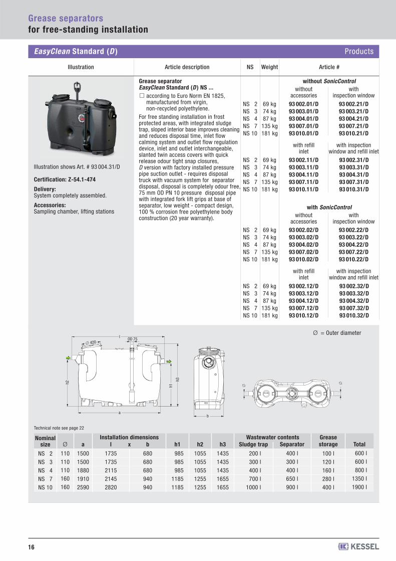
Grease separator EasyClean Standard (D ) NS ...
according to Euro Norm EN 1825,manufactured from virgin,non-recycled polyethylene.
For free standing installation in frost protected areas, with integrated sludgetrap, sloped interior base improves cleaningand reduces disposal time, inlet flowcalming system and outlet flow regulationdevice, inlet and outlet interchangeable,slanted twin access covers with quickrelease odour tight snap closures,D version with factory installed pressurepipe suction outlet - requires disposaltruck with vacuum system for separatordisposal, disposal is completely odour free,75 mm OD PN 10 pressure disposal pipewith integrated fork lift grips at base of separator, low weight - compact design,100 % corrosion free polyethylene bodyconstruction (20 year warranty).
EasyClean Standard (D ) Products
h2
a
l
h1
h3
� 420 OD 75
b
�
�
Ø = Outer diameter
Technical note see page 22
93 002.01/D93 003.01/D93 004.01/D93 007.01/D93 010.01/D
93 002.21/D93 003.21/D93 004.21/D93 007.21/D93 010.21/D
without SonicControlwithout
accessorieswith
inspection window
93 002.02/D93 003.02/D93 004.02/D93 007.02/D93 010.02/D
93 002.22/D93 003.22/D93 004.22/D93 007.22/D93 010.22/D
with SonicControlwithout
accessorieswith
inspection window
93 002.11/D93 003.11/D93 004.11/D93 007.11/D93 010.11/D
93 002.31/D93 003.31/D93 004.31/D93 007.31/D93 010.31/D
with refill inlet
with inspectionwindow and refill inlet
93 002.12/D93 003.12/D93 004.12/D93 007.12/D93 010.12/D
93 002.32/D93 003.32/D93 004.32/D93 007.32/D93 010.32/D
with refill inlet
with inspectionwindow and refill inlet
1)
Ø
110110110160160
a
15001500188019102590
b
680680680940940
h1
985985985
11851185
h2
10551055105512551255
h3
14351435143516551655
l
17351735211521452820
Sludge trap
200 l300 l400 l700 l
1000 l
Wastewater contentsSeparator
400 l300 l400 l650 l900 l
Grease storage
100 l120 l160 l280 l400 l
Nominalsize
NS 2NS 3NS 4NS 7NS 10
xInstallation dimensions
Total600 l600 l800 l
1350 l1900 l
Illustration shows Art. # 93 004.31/D
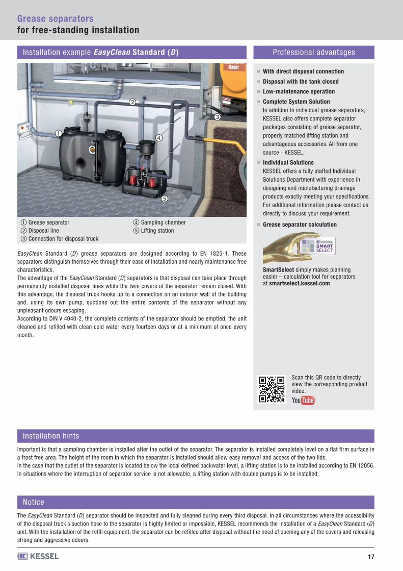
Installation example EasyClean Standard (D ) Professional advantages
EasyClean Standard (D ) grease separators are designed according to EN 1825-1. Theseseparators distinguish themselves through their ease of installation and nearly maintenance freecharacteristics. The advantage of the EasyClean Standard (D ) separators is that disposal can take place throughpermanently installed disposal lines while the twin covers of the separator remain closed. Withthis advantage, the disposal truck hooks up to a connection on an exterior wall of the buildingand, using its own pump, suctions out the entire contents of the separator without anyunpleasant odours escaping.According to DIN V 4040-2, the complete contents of the separator should be emptied, the unitcleaned and refilled with clean cold water every fourteen days or at a minimum of once everymonth.
With direct disposal connection
Disposal with the tank closed
Low-maintenance operation
17
Grease separatorsfor free-standing installation
�
�
�
�
�
Installation hints
Important is that a sampling chamber is installed after the outlet of the separator. The separator is installed completely level on a flat firm surface ina frost free area. The height of the room in which the separator is installed should allow easy removal and access of the two lids.In the case that the outlet of the separator is located below the local defined backwater level, a lifting station is to be installed according to EN 12056.In situations where the interruption of separator service is not allowable, a lifting station with double pumps is to be installed.
Notice
The EasyClean Standard (D ) separator should be inspected and fully cleaned during every third disposal. In all circumstances where the accessibilityof the disposal truck’s suction hose to the separator is highly limited or impossible, KESSEL recommends the installation of a EasyClean Standard (D )unit. With the installation of the refill equipment, the separator can be refilled after disposal without the need of opening any of the covers and releasingstrong and aggressive odours.
Scan this QR code to directly view the corresponding product video.
Complete System SolutionIn addition to individual grease separators,KESSEL also offers complete separatorpackages consisting of grease separator,properly matched lifting station andadvantageous accessories. All from onesource - KESSEL.
Individual SolutionsKESSEL offers a fully staffed IndividualSolutions Department with experience indesigning and manufacturing drainageproducts exactly meeting your specifications.For additional information please contact usdirectly to discuss your requirement.
SmartSelect simply makes planning easier – calculation tool for separators at smartselect.kessel.com
Grease separator calculation① Grease separator② Disposal line ③ Connection for disposal truck
④ Sampling chamber ⑤ Lifting station
Weight Article #NSArticle description
Illustration
18
NS 2NS 3NS 4NS 7NS 10
69 kg74 kg87 kg
135 kg181 kg
NS 2NS 3NS 4NS 7NS 10
69 kg74 kg87 kg
135 kg181 kg
NS 2NS 3NS 4NS 7NS 10
69 kg74 kg87 kg
135 kg181 kg
NS 2NS 3NS 4NS 7NS 10
69 kg74 kg87 kg
135 kg181 kg
Certification: Z-54.1-474
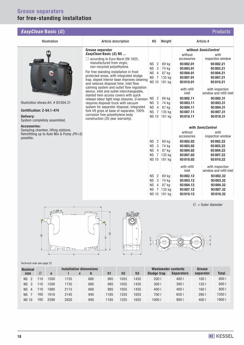
Delivery:System completely assembled.
Accessories: Sampling chamber, lifting stations.Retrofitting up to Auto Mix & Pump (PV+S)possible.
Grease separator EasyClean Basic (G ) NS ...
according to Euro Norm EN 1825,manufactured from virgin,non-recycled polyethylene.
For free standing installation in frost protected areas, with integrated sludgetrap, sloped interior base improves cleaningand reduces disposal time, inlet flowcalming system and outlet flow regulationdevice, inlet and outlet interchangeable,slanted twin access covers with quickrelease odour tight snap closures, G versionrequires disposal truck with vacuumsystem for separator disposal, integratedfork lift grips at base of separator, 100%corrosion free polyethylene bodyconstruction (20 year warranty).
EasyClean Basic (G ) Products
�
�
b
h2
a
l
h1
h3
� 420
Ø = Outer diameter
Technical note see page 22
Grease separatorsfor free-standing installation
93 002.0193 003.0193 004.0193 007.0193 010.01
93 002.2193 003.2193 004.2193 007.2193 010.21
without SonicControlwithout
accessorieswith
inspection window
93 002.0293 003.0293 004.0293 007.0293 010.02
93 002.2293 003.2293 004.2293 007.2293 010.22
with SonicControlwithout
accessorieswith
inspection window
93 002.1193 003.1193 004.1193 007.1193 010.11
93 002.3193 003.3193 004.3193 007.3193 010.31
with refill inlet
with inspectionwindow and refill inlet
93 002.1293 003.1293 004.1293 007.1293 010.12
93 002.3293 003.3293 004.3293 007.3293 010.32
with refill inlet
with inspectionwindow and refill inlet
Ø
110110110160160
a
15001500188019102590
b
680680680940940
h1
985985985
11851185
h2
10551055105512551255
h3
14351435143516551655
l
17351735211521452820
Sludge trap
200 l300 l400 l700 l
1000 l
Wastewater contentsSeparators
400 l300 l400 l650 l900 l
Grease separator
100 l120 l160 l280 l400 l
Nominalsize
NS 2NS 3NS 4NS 7NS 10
xInstallation dimensions
Total600 l600 l800 l
1350 l1900 l
Illustration shows Art. # 93 004.31
19
Grease separatorsfor free-standing installation
913 101/D
913 101/DS913 101/DS10
913 101/DSP913 101/DSP10
913 101/MS913 101/MS10
913 101/PVS913 101/PVS10
1
2
1
2
1
2
1
2
Retrofit Sets
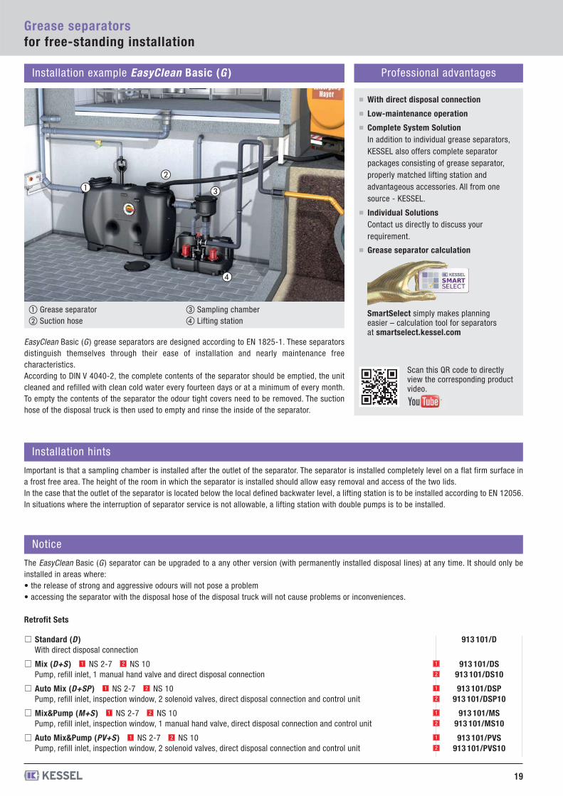
Installation example EasyClean Basic (G ) Professional advantages
EasyClean Basic (G ) grease separators are designed according to EN 1825-1. These separatorsdistinguish themselves through their ease of installation and nearly maintenance freecharacteristics.According to DIN V 4040-2, the complete contents of the separator should be emptied, the unitcleaned and refilled with clean cold water every fourteen days or at a minimum of every month.To empty the contents of the separator the odour tight covers need to be removed. The suctionhose of the disposal truck is then used to empty and rinse the inside of the separator.
With direct disposal connection
Low-maintenance operation
��
�
�
Installation hints
Important is that a sampling chamber is installed after the outlet of the separator. The separator is installed completely level on a flat firm surface ina frost free area. The height of the room in which the separator is installed should allow easy removal and access of the two lids.In the case that the outlet of the separator is located below the local defined backwater level, a lifting station is to be installed according to EN 12056.In situations where the interruption of separator service is not allowable, a lifting station with double pumps is to be installed.
Notice
The EasyClean Basic (G ) separator can be upgraded to a any other version (with permanently installed disposal lines) at any time. It should only beinstalled in areas where:• the release of strong and aggressive odours will not pose a problem• accessing the separator with the disposal hose of the disposal truck will not cause problems or inconveniences.
Scan this QR code to directly view the corresponding product video.
Complete System SolutionIn addition to individual grease separators,KESSEL also offers complete separatorpackages consisting of grease separator,properly matched lifting station andadvantageous accessories. All from onesource - KESSEL.
Individual SolutionsContact us directly to discuss yourrequirement.
SmartSelect simply makes planning easier – calculation tool for separators at smartselect.kessel.com
Standard (D )With direct disposal connection
Mix (D+S ) NS 2-7 NS 10Pump, refill inlet, 1 manual hand valve and direct disposal connection
Auto Mix (D+SP ) NS 2-7 NS 10Pump, refill inlet, inspection window, 2 solenoid valves, direct disposal connection and control unit
Mix&Pump (M+S ) NS 2-7 NS 10Pump, refill inlet, inspection window, 1 manual hand valve, direct disposal connection and control unit
Auto Mix&Pump (PV+S ) NS 2-7 NS 10Pump, refill inlet, inspection window, 2 solenoid valves, direct disposal connection and control unit
1 2
1 2
1 2
1 2
Grease separator calculation
① Grease separator② Suction hose
③ Sampling chamber ④ Lifting station
20
Grease separatorsfor free-standing installation
Euro Auto Mix & Pump (PV+S ) Products
Article description Weight Article #NSIllustration
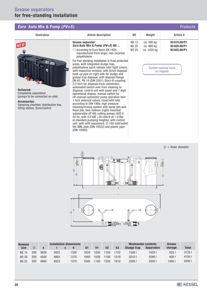
Grease separator Euro Auto Mix & Pump (PV+S ) NS ...
according to Euro Norm EN 1825,manufactured from virgin, non-recycledpolyethylene
For free standing installation in frost protectedareas, with integrated sludge trap, polyethylene quick release odor tight covers,with inspection window, with direct disposalhook up pipe on right side for sludge andgrease trap disposal, with disposal flangeDN 65, PN 10 (DIN 2501), Storz-B-coupling2.5 inch for disposal truck connection, automated switch over from cleaning to disposal, control unit with panel and 7 digitoperational display, manual switch for off-manual-automatic pump operation twin1 inch solenoid valves, rinse/refill inlet according to DIN 1988, high pressurecleaning/rinsing system with spray jets andflood jets, twin exterior (right) mounted submersible (IP 68) cutting pumps (400 V, 50 Hz, with 4.0 kW >30 cbm/h at 1.0 Bar at standard pumping heights), with controlunit, with refill equioment, Ø 160 inlet/outletfits SML pipe (DIN 19522) and plastic pipe(DIN 19560).
Ø = Outer diameter
l
h1
b1h3
h2b
a
�
�
93 015.00/P193 020.00/P193 025.00/P1
NS 15NS 20NS 25
ca. 390 kgca. 980 kg
ca. 1020 kg
Ø
200200200
a
360045004600
b
135013701370
h1
103010301180
h2
110011001250
h3
115215191619
l
392548834923
Sludge trap
1500 l2010 l2500 l
Wastewater contentsSeparators
1620 l2090 l2940 l
Grease storage
623 l800 l
1000 l
Nominalsize
NS 15NS 20NS 25
b1
162016401640
xInstallation dimensions
Total3120 l4100 l5400 l
Delivered:Completely assembled (pumps to be connected on-site)
Accessories: Sampling chamber, distribution box, lifting station, SonicControl
Further nominal sizes on request
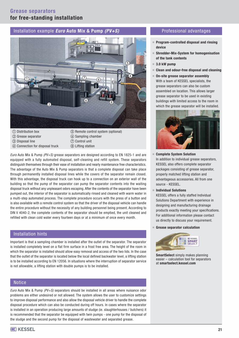
Installation example Euro Auto Mix & Pump (PV+S) Professional advantages
Program-controlled disposal and rinsingdevice
Shredder-Mix-System for homogenisationof the tank contents
3.0 kW pump
Clean and odour-free disposal and cleaning
On-site grease separator assemblyWith a team of KESSEL specialists, thegrease separators can also be customassembled on location. This allows largergrease separator to be used in existingbuildings with limited access to the room inwhich the grease separator will be installed.
Complete System SolutionIn addition to individual grease separators,KESSEL also offers complete separatorpackages consisting of grease separator,properly matched lifting station andadvantageous accessories. All from onesource - KESSEL.
Individual SolutionsKESSEL offers a fully staffed IndividualSolutions Department with experience indesigning and manufacturing drainageproducts exactly meeting your specifications.For additional information please contactus directly to discuss your requirement.
Grease separator calculation
Euro Auto Mix & Pump (PV+S) grease separators are designed according to EN 1825-1 and areequipped with a fully automated disposal, self-cleaning and refill system. These separatorsdistinguish themselves through their ease of installation and nearly maintenance free characteristics.The advantage of the Auto Mix & Pump separators is that a complete disposal can take placethrough permanently installed disposal lines while the covers of the separator remain closed.With this advantage, the disposal truck can hook up to a connection on an exterior wall of thebuilding so that the pump of the separator can pump the separator contents into the waitingdisposal truck without any unpleasant odors escaping. After the contents of the separator have beenpumped out, the interior of the separator is automatically rinsed and cleaned with warm water ina multi-step automated process. The complete procedure occurs with the press of a button andis also available with a remote control system so that the driver of the disposal vehicle can handlethe entire procedure without the necessity of any building personnel being present. According toDIN V 4040-2, the complete contents of the separator should be emptied, the unit cleaned andrefilled with clean cold water every fourteen days or at a minimum of once every month.
SmartSelect simply makes planning easier – calculation tool for separators at smartselect.kessel.com
Grease separatorsfor free-standing installation
21
Installation hints
Important is that a sampling chamber is installed after the outlet of the separator. The separatoris installed completely level on a flat firm surface in a frost free area. The height of the room inwhich the separator is installed should allow easy removal and access of the two lids. In the casethat the outlet of the separator is located below the local defined backwater level, a lifting stationis to be installed according to EN 12056. In situations where the interruption of separator serviceis not allowable, a lifting station with double pumps is to be installed.
Notice
Euro Auto Mix & Pump (PV+S) separators should be installed in all areas where nuisance odorproblems are either undesired or not allowed. The system allows the user to customize settingsto improve disposal performance and also allow the disposal vehicle driver to handle the completedisposal procedure which can also be conducted during off hours. In cases where the separatoris installed in an operation producing large amounts of sludge (ie. slaughterhouses / butchers) itis recommended that the separator be equipped with twin pumps - one pump for the disposal ofthe sludge and the second pump for the disposal of wastewater and separated grease.
① Distribution box② Grease separator ③ Disposal line ④ Connection for disposal truck
⑤ Remote control system (optional)⑥ Sampling chamber ⑦ Control unit ⑧ Lifting station
�
�
� �
�
��
�
22
Grease separatorsfor free-standing installation
Delivery:System completely assembled.
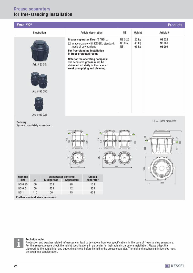
Grease separator Euro “G” NS ... in accordance with KESSEL standard,made of polyethylene
For free-standing installation in frost-protected rooms
Note for the operating company:The separated grease must be skimmed off daily in the case of weekly emptying and cleaning.
Ø = Outer diameter
93 02593 05093 001
NS 0.25NS 0.5NS 1
20 kg45 kg65 kg
710
570
520
510
540
710
570
520
510
1150
1200
1020
453500
990
�
�
Ø
5050
110
Sludge trap
25 l50 l
100 l
Separators
28 l42 l75 l
Grease separator
15 l30 l60 l
Nominalsize
NS 0.25NS 0.5NS 1
Art. # 93 001
Wastewater contents
Art. # 93 025
Art. # 93 050
Technical note:Production and weather related influences can lead to deviations from our specifications in the case of free-standing separators. For this reason, please check the height specifications in particular for their actual size before installation. Please adapt the pipework to the actual inlet and outlet dimensions before installing the grease separator. Thermal and mechanical influences must be taken into consideration.
Euro “G” Products
Illustration Article description Weight Article #NS
i
Further nominal sizes on request
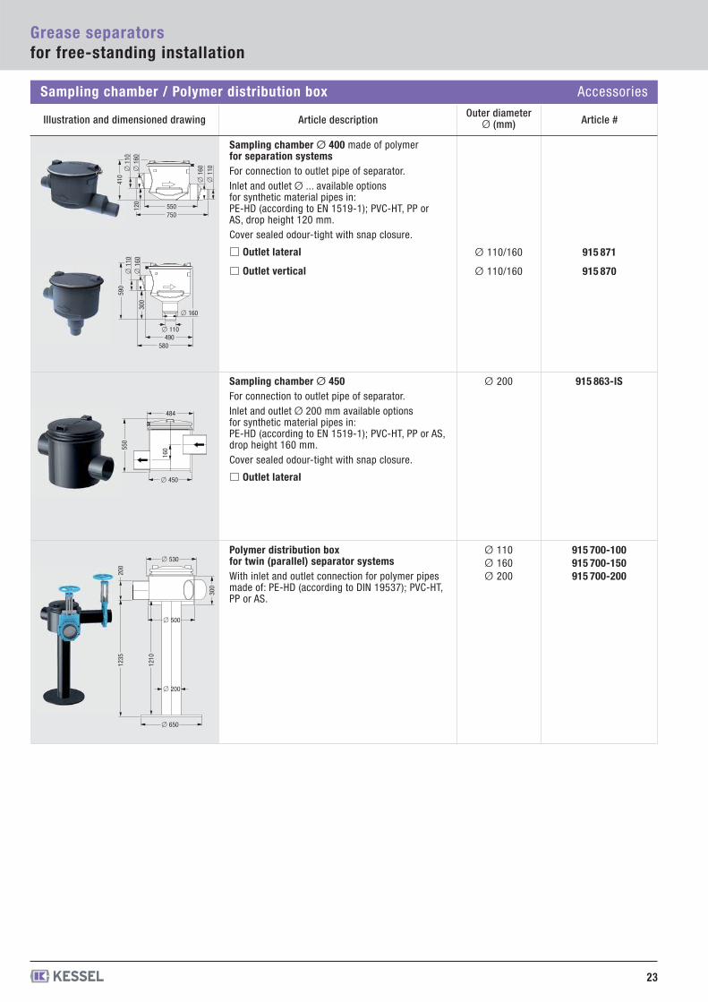
Polymer distribution boxfor twin (parallel) separator systemsWith inlet and outlet connection for polymer pipesmade of: PE-HD (according to DIN 19537); PVC-HT,PP or AS.
915 700-100915 700-150915 700-200
Ø 110Ø 160Ø 200
Sampling chamber Ø 450For connection to outlet pipe of separator. Inlet and outlet Ø 200 mm available options for synthetic material pipes in:PE-HD (according to EN 1519-1); PVC-HT, PP or AS,drop height 160 mm.Cover sealed odour-tight with snap closure.
Outlet lateral
915 863-ISØ 200
Article descriptionOuter diameter
Ø (mm) Article #
23
Grease separatorsfor free-standing installation
Illustration and dimensioned drawing
915 871
915 870
Ø 110/160
Ø 110/160
Sampling chamber Ø 400 made of polymerfor separation systemsFor connection to outlet pipe of separator. Inlet and outlet Ø ... available options for synthetic material pipes in:PE-HD (according to EN 1519-1); PVC-HT, PP orAS, drop height 120 mm.Cover sealed odour-tight with snap closure.
Outlet lateral
Outlet vertical
75055012
0
410
� 1
10�
160
� 1
10
� 1
60
580490
� 110
300
590
� 1
10�
160
� 160
� 450
550
484
160
� 650
� 530
� 500
� 200
300
1235
200
1210
Sampling chamber / Polymer distribution box Accessories
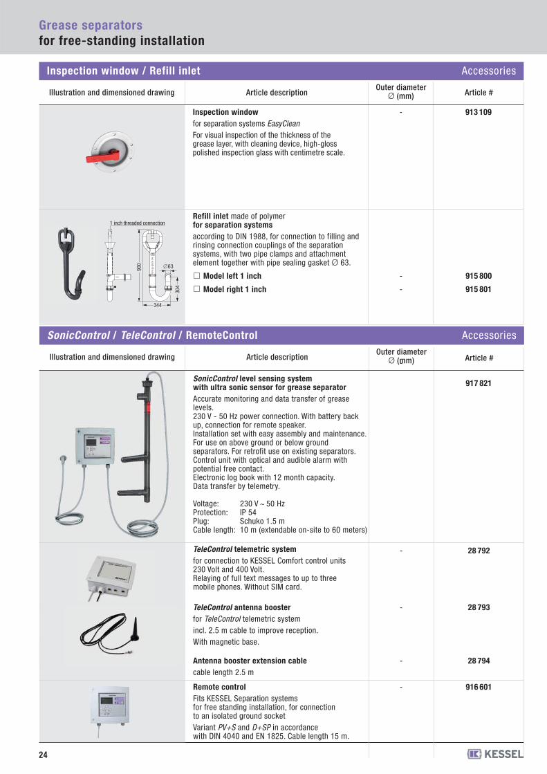
Inspection windowfor separation systems EasyCleanFor visual inspection of the thickness of the grease layer, with cleaning device, high-gloss polished inspection glass with centimetre scale.
913 109-
24
Grease separatorsfor free-standing installation
Inspection window / Refill inlet Accessories
Article descriptionOuter diameter
Ø (mm) Article #Illustration and dimensioned drawing
915 800-
915 801-
Refill inlet made of polymerfor separation systemsaccording to DIN 1988, for connection to filling andrinsing connection couplings of the separationsystems, with two pipe clamps and attachmentelement together with pipe sealing gasket Ø 63.
Model left 1 inch
Model right 1 inch
344
900
304
�63
1 inch threaded connection
28 794Antenna booster extension cablecable length 2.5 m
28 792TeleControl telemetric systemfor connection to KESSEL Comfort control units230 Volt and 400 Volt. Relaying of full text messages to up to threemobile phones. Without SIM card.
28 793
-
-
-TeleControl antenna boosterfor TeleControl telemetric systemincl. 2.5 m cable to improve reception.With magnetic base.
SonicControl level sensing system with ultra sonic sensor for grease separatorAccurate monitoring and data transfer of greaselevels. 230 V - 50 Hz power connection. With battery backup, connection for remote speaker.Installation set with easy assembly and maintenance.For use on above ground or below groundseparators. For retrofit use on existing separators.Control unit with optical and audible alarm withpotential free contact.Electronic log book with 12 month capacity.Data transfer by telemetry.
Voltage: 230 V ~ 50 Hz Protection: IP 54Plug: Schuko 1.5 mCable length: 10 m (extendable on-site to 60 meters)
917 821
-
916 601-Remote controlFits KESSEL Separation systems for free standing installation, for connection to an isolated ground socketVariant PV+S and D+SP in accordance with DIN 4040 and EN 1825. Cable length 15 m.
SonicControl / TeleControl / RemoteControl Accessories
Article descriptionOuter diameter
Ø (mm) Article #Illustration and dimensioned drawing
25
Grease seperator Euro GNS 1 - 4
Grease seperator Euro GNS 7 - 35
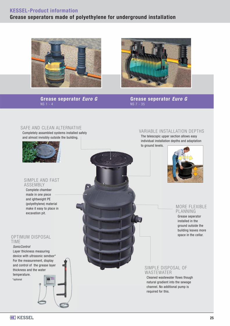
KESSEL-Product informationGrease seperators made of polyethylene for underground installation
VARIABLE INSTALLATION DEPTHSThe telescopic upper section allows easyindividual installation depths and adaptationto ground levels.
SAFE AND CLEAN ALTERNATIVECompletely assambled systems installed safelyand almost invisibly outside the building.
SIMPLE AND FASTASSEMBLY
Complete chambermade in one pieceand ightweight PE(polyethylene) materialmake it easy to place inexcavation pit.
MORE FLEXIBLEPLANNING
Grease seperatorinstalled in theground outside thebuilding leaves morespace in the cellar.
SIMPLE DISPOSAL OFWASTEWATER
Cleaned wastewater flows thoughnatural gradient into the sewagechannel. No additional pump isrequired for this.
OPTIMUM DISPOSALTIME
SonicControlLayer thickness measuringdevice with ultrasonic sendsor*For the measurement, displayand control of the grease layerthickness and the watertemperature.*optional
26
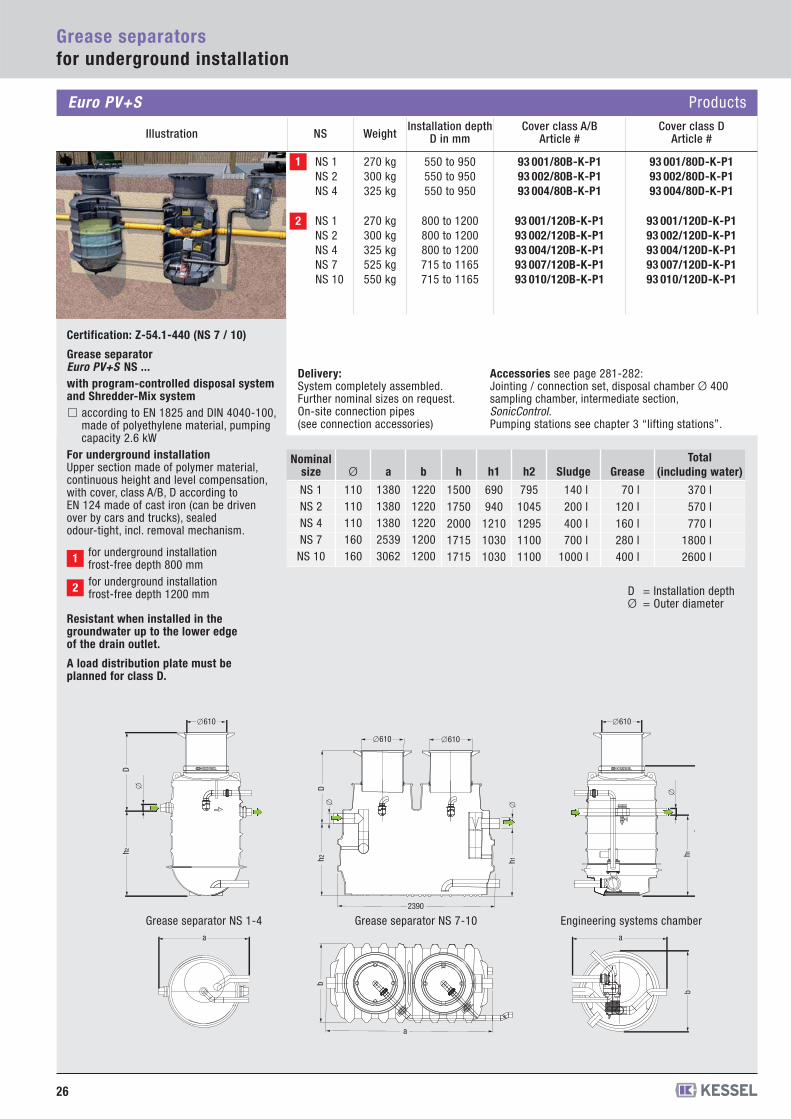
Euro PV+S Products
Grease separatorsfor underground installation
93 001/80D-K-P193 002/80D-K-P193 004/80D-K-P1
270 kg300 kg325 kg
550 to 950550 to 950550 to 950
NS 1NS 2NS 4
93 001/120B-K-P193 002/120B-K-P193 004/120B-K-P193 007/120B-K-P193 010/120B-K-P1
93 001/120D-K-P193 002/120D-K-P193 004/120D-K-P193 007/120D-K-P193 010/120D-K-P1
270 kg300 kg325 kg525 kg550 kg
800 to 1200800 to 1200800 to 1200715 to 1165715 to 1165
NS 1NS 2NS 4NS 7NS 10
Delivery:System completely assembled.Further nominal sizes on request.On-site connection pipes(see connection accessories)
Nominalsize
NS 1NS 2NS 4NS 7
NS 10
Ø
110110110160160
a
13801380138025393062
b
12201220122012001200
h
15001750200017151715
h1
690940
121010301030
h2
7951045129511001100
Sludge
140 l200 l400 l700 l
1000 l
Grease
70 l120 l160 l280 l400 l
Total (including water)
370 l570 l770 l
1800 l2600 l
D = Installation depth Ø = Outer diameter
1
2
93 001/80B-K-P193 002/80B-K-P193 004/80B-K-P1
Accessories see page 281-282:Jointing / connection set, disposal chamber Ø 400 sampling chamber, intermediate section, SonicControl.Pumping stations see chapter 3 “lifting stations”.
for underground installation frost-free depth 800 mm1
for underground installation frost-free depth 1200 mm2
Illustration NS WeightInstallation depth
D in mm Article #Cover class D
Article #Cover class A/B
Certification: Z-54.1-440 (NS 7 / 10)
Grease separator Euro PV+S NS ...with program-controlled disposal systemand Shredder-Mix system
according to EN 1825 and DIN 4040-100,made of polyethylene material, pumpingcapacity 2.6 kW
For underground installationUpper section made of polymer material,continuous height and level compensation,with cover, class A/B, D according toEN 124 made of cast iron (can be drivenover by cars and trucks), sealedodour-tight, incl. removal mechanism.
Resistant when installed in the groundwater up to the lower edge of the drain outlet.
A load distribution plate must be planned for class D.
�610
h1h
a
b
�
�610
h2D
a
� Dh2
b
h1�
a
2390
�
�610�610
Grease separator NS 1-4 Engineering systems chamberGrease separator NS 7-10
27
Grease separatorsfor underground installation
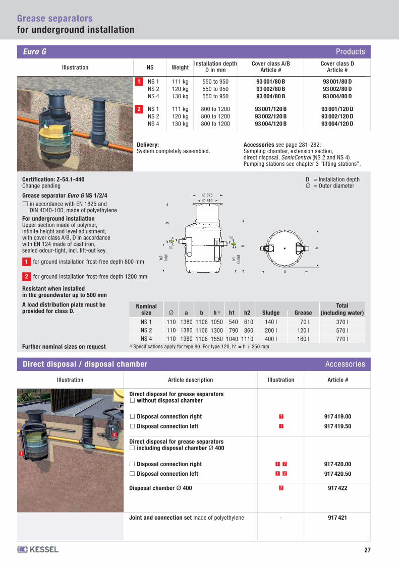
Euro G Products
1
Illustration NS WeightInstallation depth
D in mm Article #Cover class D
Article #Cover class A/B
93 001/80 B93 002/80 B93 004/80 B
93 001/120 B93 002/120 B93 004/120 B
93 001/80 D93 002/80 D93 004/80 D
93 001/120 D93 002/120 D93 004/120 D
111 kg120 kg130 kg
111 kg120 kg130 kg
550 to 950550 to 950550 to 950
800 to 1200800 to 1200800 to 1200
NS 1NS 2NS 4
NS 1NS 2NS 4
2
Delivery:System completely assembled.
Accessories see page 281-282:Sampling chamber, extension section, direct disposal, SonicControl (NS 2 and NS 4).Pumping stations see chapter 3 “lifting stations”.
� 875
h
� 610
�
h2 h1
� b
a
D = Installation depth Ø = Outer diameter
Certification: Z-54.1-440 Change pending
Grease separator Euro G NS 1/2/4 in accordance with EN 1825 andDIN 4040-100, made of polyethylene
For underground installationUpper section made of polymer, infinite height and level adjustment, with cover class A/B, D in accordance with EN 124 made of cast iron, sealed odour-tight, incl. lift-out key.
Resistant when installed in the groundwater up to 500 mm
A load distribution plate must be provided for class D.
for ground installation frost-free depth 800 mm1
for ground installation frost-free depth 1200 mm2
Inle
tD
Outle
t
Nominalsize
NS 1NS 2NS 4
Ø
110110110
a
138013801380
b
110611061106
h 1)
105013001550
h1
540790
1040
h2
610860
1110
Sludge
140 l200 l400 l
Grease
70 l120 l160 l
Total (including water)
370 l570 l770 l
1) Specifications apply for type 80. For type 120, h* = h + 250 mm.Further nominal sizes on request
Article description Illustration Article #
Illustration
917 419.00
917 419.50
Direct disposal for grease separatorswithout disposal chamber
Disposal connection right
Disposal connection left
1
1
2
1
1
2
2
Direct disposal / disposal chamber Accessories
917 421-Joint and connection set made of polyethylene
917 422Disposal chamber Ø 400
917 420.00
917 420.50
Direct disposal for grease separatorsincluding disposal chamber Ø 400
Disposal connection right
Disposal connection left
1
2
93 007/120 B93 010/120 B93 015/120 B93 020/120 B
93 925/120 B93 930/120 B93 935/120 B
93 007/120 D93 010/120 D93 015/120 D93 020/120 D
93 925/120 D93 930/120 D93 935/120 D
450 kg480 kg630 kg670 kg
765 kg765 kg765 kg
745 to 1180755 to 1190755 to 1190750 to 1185
810 to 1245810 to 1245660 to 1095
NS 7*NS 10*NS 15*NS 20*
NS 25NS 30NS 35
BL
h1h2
� �
DEC*
*UET
L max
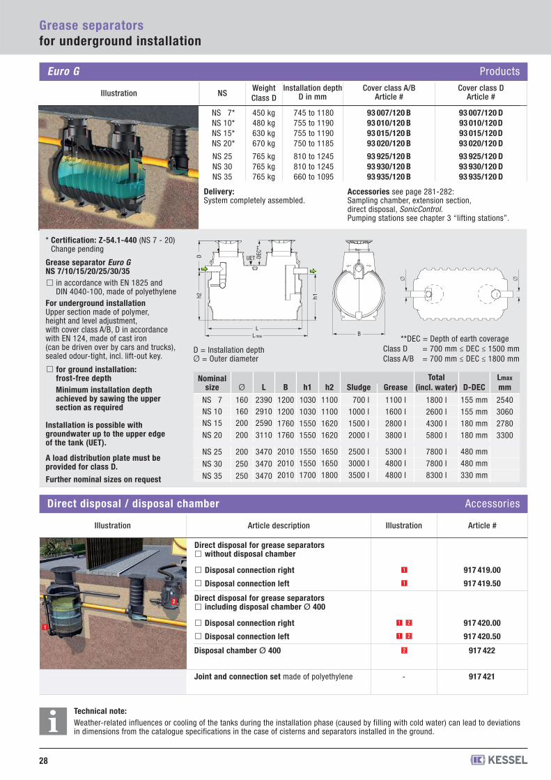
Delivery:System completely assembled.
Accessories see page 281-282:Sampling chamber, extension section, direct disposal, SonicControl. Pumping stations see chapter 3 “lifting stations”.
Nominalsize
NS 7NS 10NS 15
NS 20
NS 25
NS 30
NS 35
Ø
160160200
200
200
250
250
L
239029102590
3110
3470
3470
3470
B
1200120017601760
201020102010
h1
1030103015501550
155015501700
h2
1100110016201620
165016501800
Sludge
700 l1000 l1500 l2000 l
2500 l3000 l3500 l
Grease
1100 l1600 l2800 l3800 l
5300 l4800 l4800 l
D-DEC
155 mm155 mm180 mm180 mm
480 mm480 mm330 mm
D = Installation depth Ø = Outer diameter
**DEC = Depth of earth coverageClass D = 700 mm ≤ DEC ≤ 1500 mmClass A/B = 700 mm ≤ DEC ≤ 1800 mm
D
* Certification: Z-54.1-440 (NS 7 - 20)Change pending
Grease separator Euro GNS 7/10/15/20/25/30/35
in accordance with EN 1825 andDIN 4040-100, made of polyethylene
For underground installationUpper section made of polymer, height and level adjustment, with cover class A/B, D in accordance with EN 124, made of cast iron (can be driven over by cars and trucks), sealed odour-tight, incl. lift-out key.
for ground installation:frost-free depth Minimum installation depthachieved by sawing the uppersection as required
Installation is possible with groundwater up to the upper edge of the tank (UET).
A load distribution plate must be provided for class D.
28
Grease separatorsfor underground installation
Euro G Products
Illustration NSWeightClass D
Installation depthD in mm Article #
Cover class DArticle #
Cover class A/B
Technical note: Weather-related influences or cooling of the tanks during the installation phase (caused by filling with cold water) can lead to deviationsin dimensions from the catalogue specifications in the case of cisterns and separators installed in the ground.i
Further nominal sizes on request
Article description Illustration Article #
Illustration
917 419.00
917 419.50
Direct disposal for grease separatorswithout disposal chamber
Disposal connection right
Disposal connection left
1
1
2
1
1
2
2
Direct disposal / disposal chamber Accessories
917 421-Joint and connection set made of polyethylene
917 422Disposal chamber Ø 400
917 420.00
917 420.50
Direct disposal for grease separatorsincluding disposal chamber Ø 400
Disposal connection right
Disposal connection left 1
2
Total (incl. water)
1800 l2600 l4300 l5800 l
7800 l7800 l8300 l
Lmax
mm
2540306027803300
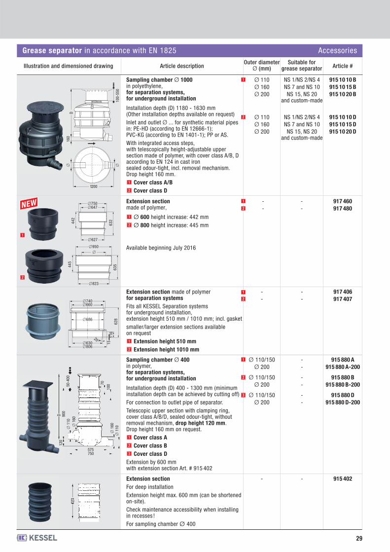
Extension section made of polymerfor separation systemsFits all KESSEL Separation systemsfor underground installation,extension height 510 mm / 1010 mm; incl. gasketsmaller/larger extension sections available on request
Extension height 510 mmExtension height 1010 mm
--
--
917 406917 407
Sampling chamber Ø 1000in polyethylene,for separation systems, for underground installation
Installation depth (D) 1180 - 1630 mm (Other installation depths available on request)Inlet and outlet Ø ... for synthetic material pipesin: PE-HD (according to EN 12666-1); PVC-KG (according to EN 1401-1); PP or AS.With integrated access steps, with telescopically height-adjustable uppersection made of polymer, with cover class A/B, D according to EN 124 in cast ironsealed odour-tight, incl. removal mechanism.Drop height 160 mm.
Cover class A/BCover class D
915 10 10 B915 10 15 B915 10 20 B
915 10 10 D915 10 15 D915 10 20 D
NS 1/NS 2/NS 4NS 7 and NS 10NS 15, NS 20
and custom-made
NS 1/NS 2/NS 4NS 7 and NS 10NS 15, NS 20
and custom-made
Ø 110Ø 160Ø 200
Ø 110Ø 160Ø 200
1
2
1
2
2
1
1
2
�660
�630�806
�686
�740
116
15
628
20°
Sampling chamber Ø 400 in polymer,for separation systems, for underground installation
Installation depth (D) 400 - 1300 mm (minimuminstallation depth can be achieved by cutting off)For connection to outlet pipe of separator.Telescopic upper section with clamping ring, cover class A/B/D, sealed odour-tight, without removal mechanism, drop height 120 mm.Drop height 160 mm on request.
Cover class ACover class BCover class D
Extension by 600 mm with extension section Art. # 915 402
Ø 110/150Ø 200
Ø 110/150Ø 200
Ø 110/150Ø 200
--
--
--
915 880 A915 880 A-200
915 880 B915 880 B-200
915 880 D915 880 D-200
Extension section For deep installationExtension height max. 600 mm (can be shortenedon-site).Check maintenance accessibility when installingin recesses !For sampling chamber Ø 400
-- 915 402
1
2
3
1
2
3
160
� �
1200
100-
550
D
575750
120
50-4
00
70
100
� 1
60�
110
900
� 1
10�
160
D
Article descriptionSuitable for
grease separatorOuter diameter
Ø (mm) Article #Illustration and dimensioned drawing
29
Grease separatorsfor underground installation
Grease separator in accordance with EN 1825 Accessories
Extension section made of polymer,
Ø 600 height increase: 442 mmØ 800 height increase: 445 mm
--
--
917 460917 480
1
2
1
2
�627
�750�647
632442
�823
�950�
63544
5
1
2
Available beginning July 2016
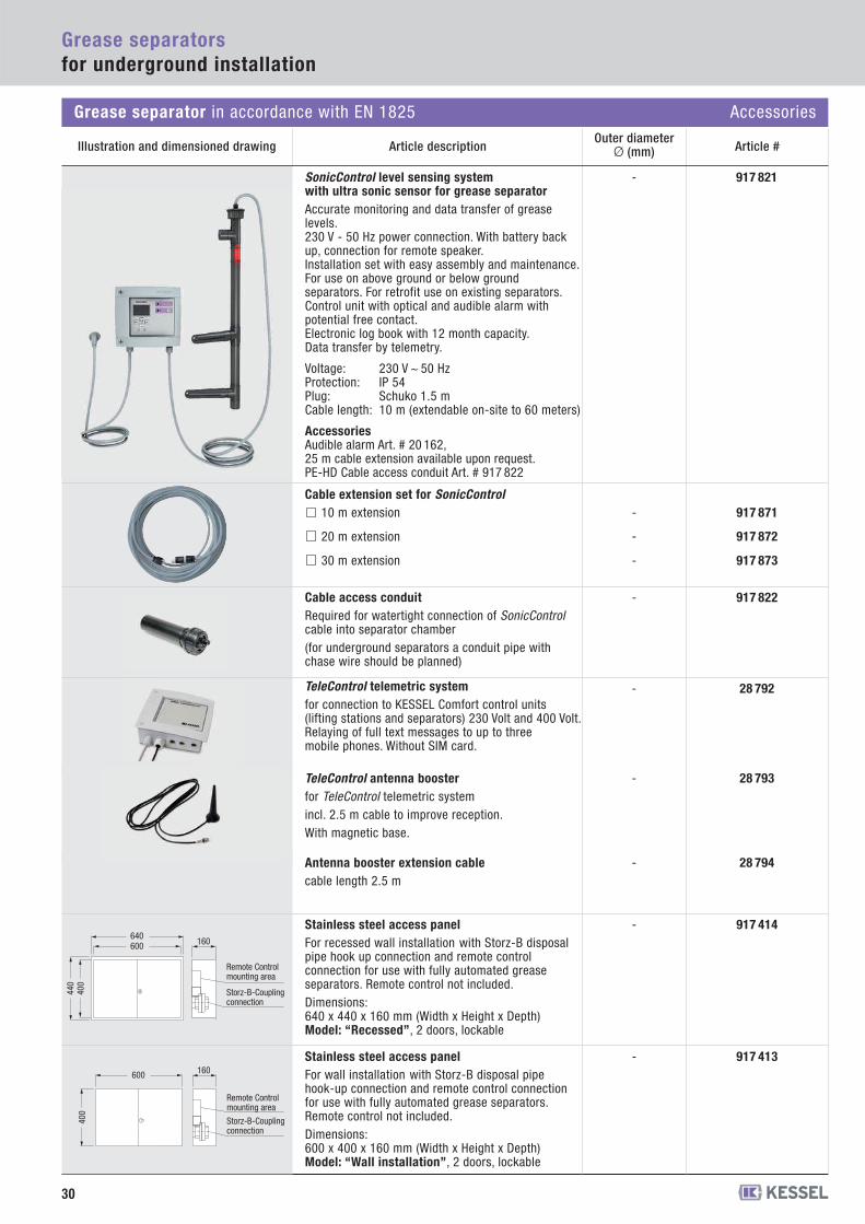
Cable extension set for SonicControl 10 m extension
20 m extension
30 m extension
- 917 871
- 917 872
- 917 873
28 794Antenna booster extension cablecable length 2.5 m
28 792TeleControl telemetric systemfor connection to KESSEL Comfort control units(lifting stations and separators) 230 Volt and 400 Volt. Relaying of full text messages to up to threemobile phones. Without SIM card.
28 793
-
-
-TeleControl antenna boosterfor TeleControl telemetric systemincl. 2.5 m cable to improve reception.With magnetic base.
917 822-Cable access conduit Required for watertight connection of SonicControlcable into separator chamber(for underground separators a conduit pipe withchase wire should be planned)
SonicControl level sensing system with ultra sonic sensor for grease separatorAccurate monitoring and data transfer of greaselevels. 230 V - 50 Hz power connection. With battery backup, connection for remote speaker.Installation set with easy assembly and maintenance.For use on above ground or below groundseparators. For retrofit use on existing separators.Control unit with optical and audible alarm withpotential free contact.Electronic log book with 12 month capacity.Data transfer by telemetry.
Voltage: 230 V ~ 50 Hz Protection: IP 54Plug: Schuko 1.5 mCable length: 10 m (extendable on-site to 60 meters)
AccessoriesAudible alarm Art. # 20 162,25 m cable extension available upon request.PE-HD Cable access conduit Art. # 917 822
917 821-
30
Grease separatorsfor underground installation
Grease separator in accordance with EN 1825 Accessories
Article descriptionOuter diameter
Ø (mm) Article #Illustration and dimensioned drawing
160
Remote Control mounting area
Storz-B-Coupling connection
640600
440
400
917 414-Stainless steel access panelFor recessed wall installation with Storz-B disposalpipe hook up connection and remote controlconnection for use with fully automated greaseseparators. Remote control not included.Dimensions: 640 x 440 x 160 mm (Width x Height x Depth)Model: “Recessed”, 2 doors, lockable
600
400
160
Remote Control mounting area
Storz-B-Coupling connection
917 413-Stainless steel access panelFor wall installation with Storz-B disposal pipehook-up connection and remote control connectionfor use with fully automated grease separators.Remote control not included.Dimensions: 600 x 400 x 160 mm (Width x Height x Depth)Model: “Wall installation”, 2 doors, lockable
31
Grease separators –Size Calculation
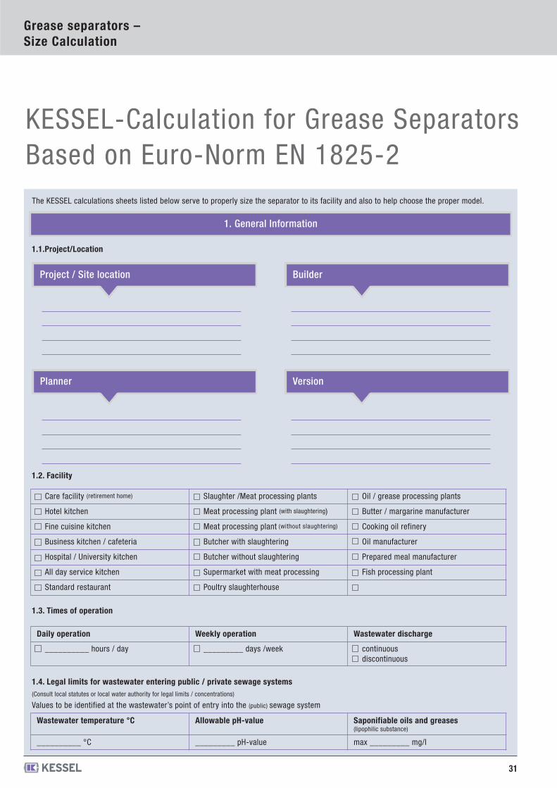
The KESSEL calculations sheets listed below serve to properly size the separator to its facility and also to help choose the proper model.
KESSEL-Calculation for Grease SeparatorsBased on Euro-Norm EN 1825-2
1. General Information
1.1.Project/Location
Version
1.2. Facility
Care facility (retirement home) Slaughter /Meat processing plants Oil / grease processing plants
Hotel kitchen Meat processing plant (with slaughtering) Butter / margarine manufacturer
Fine cuisine kitchen Meat processing plant (without slaughtering) Cooking oil refinery
Business kitchen / cafeteria Butcher with slaughtering Oil manufacturer
Hospital / University kitchen Butcher without slaughtering Prepared meal manufacturer
All day service kitchen Supermarket with meat processing Fish processing plant
Standard restaurant Poultry slaughterhouse
Project / Site location Builder
Planner
1.3. Times of operation
Daily operation Weekly operation Wastewater discharge
__________ hours / day _________ days /week continuousdiscontinuous
1.4. Legal limits for wastewater entering public / private sewage systems(Consult local statutes or local water authority for legal limits / concentrations)
Values to be identified at the wastewater’s point of entry into the (public) sewage system
Wastewater temperature °C Allowable pH-value Saponifiable oils and greases(lipophilic substance)
__________ °C _________ pH-value max _________ mg/l
32
Grease separators –Size Calculation
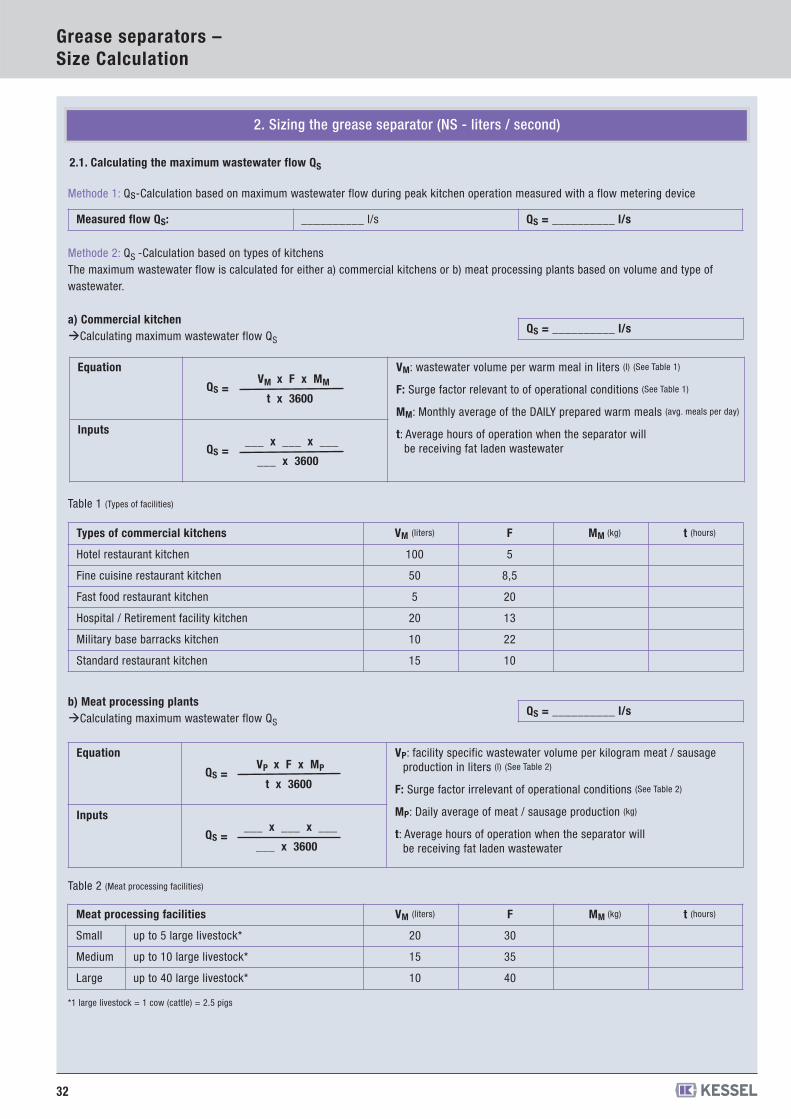
Methode 1: Qs-Calculation based on maximum wastewater flow during peak kitchen operation measured with a flow metering device
2. Sizing the grease separator (NS - liters / second)
2.1. Calculating the maximum wastewater flow QS
Measured flow QS: __________ l/s QS = __________ l/s
Methode 2: QS -Calculation based on types of kitchensThe maximum wastewater flow is calculated for either a) commercial kitchens or b) meat processing plants based on volume and type ofwastewater.
a) Commercial kitchen�Calculating maximum wastewater flow QS
Table 1 (Types of facilities)
b) Meat processing plants�Calculating maximum wastewater flow QS
Table 2 (Meat processing facilities)
*1 large livestock = 1 cow (cattle) = 2.5 pigs
QS = __________ l/s
Types of commercial kitchens VM (liters) F MM (kg) t (hours)
Hotel restaurant kitchen 100 5
Fine cuisine restaurant kitchen 50 8,5
Fast food restaurant kitchen 5 20
Hospital / Retirement facility kitchen 20 13
Military base barracks kitchen 10 22
Standard restaurant kitchen 15 10
QS = __________ l/s
Equation
QS = VP x F x MP
t x 3600
VP: facility specific wastewater volume per kilogram meat / sausageproduction in liters (l) (See Table 2)
F: Surge factor irrelevant of operational conditions (See Table 2)
MP: Daily average of meat / sausage production (kg)
t: Average hours of operation when the separator willbe receiving fat laden wastewater
Inputs
QS = ___ x ___ x ___
___ x 3600
Meat processing facilities VM (liters) F MM (kg) t (hours)
Small up to 5 large livestock* 20 30
Medium up to 10 large livestock* 15 35
Large up to 40 large livestock* 10 40
Equation
QS = VM x F x MM
t x 3600
VM: wastewater volume per warm meal in liters (l) (See Table 1)
F: Surge factor relevant to of operational conditions (See Table 1)
MM: Monthly average of the DAILY prepared warm meals (avg. meals per day)
t: Average hours of operation when the separator willbe receiving fat laden wastewater
Inputs
QS = ___ x ___ x ___
___ x 3600
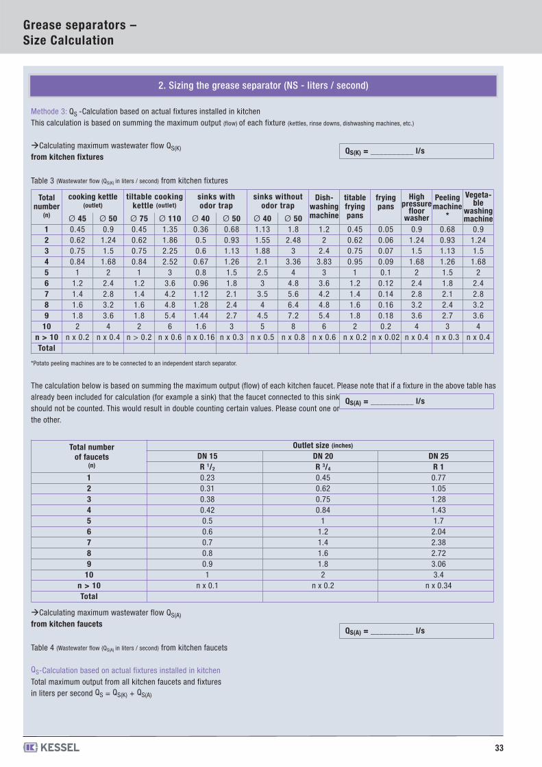
33
Grease separators –Size Calculation
Methode 3: QS -Calculation based on actual fixtures installed in kitchenThis calculation is based on summing the maximum output (flow) of each fixture (kettles, rinse downs, dishwashing machines, etc.)
�Calculating maximum wastewater flow QS(K)
from kitchen fixtures
Table 3 (Wastewater flow (QS(K) in liters / second) from kitchen fixtures
*Potato peeling machines are to be connected to an independent starch separator.
The calculation below is based on summing the maximum output (flow) of each kitchen faucet. Please note that if a fixture in the above table hasalready been included for calculation (for example a sink) that the faucet connected to this sinkshould not be counted. This would result in double counting certain values. Please count one orthe other.
�Calculating maximum wastewater flow QS(A)
from kitchen faucets
Table 4 (Wastewater flow (QS(A) in liters / second) from kitchen faucets
QS-Calculation based on actual fixtures installed in kitchenTotal maximum output from all kitchen faucets and fixturesin liters per second QS = QS(K) + QS(A)
QS(K) = __________ l/s
Totalnumber
(n)
cooking kettle(outlet)
tiltable cookingkettle (outlet)
sinks withodor trap
sinks withoutodor trap
Dish-washingmachine
titablefryingpans
fryingpans
Highpressure
floorwasher
Peelingmachine
*
Vegeta-ble
washingmachineØ 45 Ø 50 Ø 75 Ø 110 Ø 40 Ø 50 Ø 40 Ø 50
1 0.45 0.9 0.45 1.35 0.36 0.68 1.13 1.8 1.2 0.45 0.05 0.9 0.68 0.92 0.62 1.24 0.62 1.86 0.5 0.93 1.55 2.48 2 0.62 0.06 1.24 0.93 1.243 0.75 1.5 0.75 2.25 0.6 1.13 1.88 3 2.4 0.75 0.07 1.5 1.13 1.54 0.84 1.68 0.84 2.52 0.67 1.26 2.1 3.36 3.83 0.95 0.09 1.68 1.26 1.685 1 2 1 3 0.8 1.5 2.5 4 3 1 0.1 2 1.5 26 1.2 2.4 1.2 3.6 0.96 1.8 3 4.8 3.6 1.2 0.12 2.4 1.8 2.47 1.4 2.8 1.4 4.2 1.12 2.1 3.5 5.6 4.2 1.4 0.14 2.8 2.1 2.88 1.6 3.2 1.6 4.8 1.28 2.4 4 6.4 4.8 1.6 0.16 3.2 2.4 3.29 1.8 3.6 1.8 5.4 1.44 2.7 4.5 7.2 5.4 1.8 0.18 3.6 2.7 3.6
10 2 4 2 6 1.6 3 5 8 6 2 0.2 4 3 4n > 10 n x 0.2 n x 0.4 n > 0.2 n x 0.6 n x 0.16 n x 0.3 n x 0.5 n x 0.8 n x 0.6 n x 0.2 n x 0.02 n x 0.4 n x 0.3 n x 0.4Total
QS(A) = __________ l/s
Total number of faucets
(n)
Outlet size (inches)
DN 15 DN 20 DN 25R 1/2 R 3/4 R 1
1 0.23 0.45 0.772 0.31 0.62 1.053 0.38 0.75 1.284 0.42 0.84 1.435 0.5 1 1.76 0.6 1.2 2.047 0.7 1.4 2.388 0.8 1.6 2.729 0.9 1.8 3.06
10 1 2 3.4n > 10 n x 0.1 n x 0.2 n x 0.34Total
QS(A) = __________ l/s
2. Sizing the grease separator (NS - liters / second)
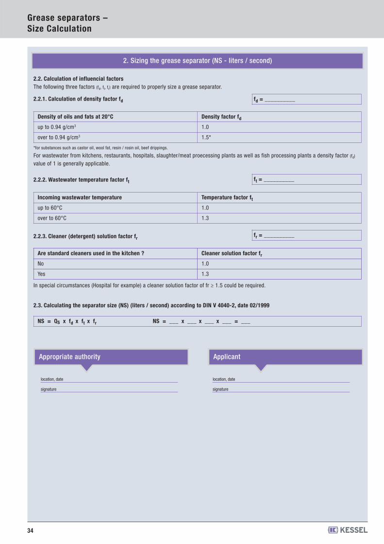
34
Grease separators –Size Calculation
2.2.1. Calculation of density factor fd
*for substances such as castor oil, wool fat, resin / rosin oil, beef drippings.
For wastewater from kitchens, restaurants, hospitals, slaughter/meat proecessing plants as well as fish processing plants a density factor (fd)
value of 1 is generally applicable.
2.2.2. Wastewater temperature factor ft
2.2.3. Cleaner (detergent) solution factor fr
In special circumstances (Hospital for example) a cleaner solution factor of fr ≥ 1.5 could be required.
2.2. Calculation of influencial factorsThe following three factors (fd, ft, fr) are required to properly size a grease separator.
Density of oils and fats at 20°C Density factor fd
up to 0.94 g/cm3 1.0
over to 0.94 g/cm3 1.5*
fd = __________
Incoming wastewater temperature Temperature factor ft
up to 60°C 1.0
over to 60°C 1.3
ft = __________
fr = __________
2.3. Calculating the separator size (NS) (liters / second) according to DIN V 4040-2, date 02/1999
NS = QS x fd x ft x fr NS = ___ x ___ x ___ x ___ = ___
location, date
signature
Appropriate authority Applicant
location, date
signature
Are standard cleaners used in the kitchen ? Cleaner solution factor fr
No 1.0
Yes 1.3
2. Sizing the grease separator (NS - liters / second)
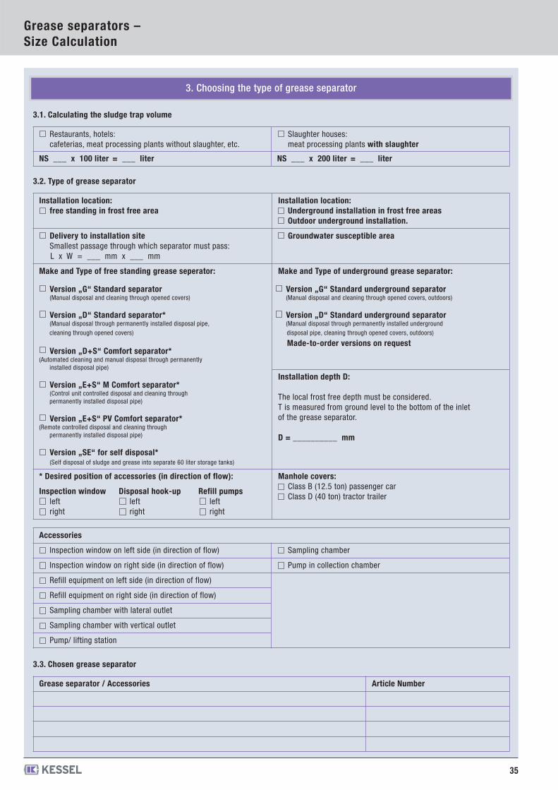
35
Grease separators –Size Calculation
3. Choosing the type of grease separator
3.1. Calculating the sludge trap volume
Restaurants, hotels:cafeterias, meat processing plants without slaughter, etc.
Slaughter houses:meat processing plants with slaughter
NS ___ x 100 liter = ___ liter NS ___ x 200 liter = ___ liter
3.2. Type of grease separator
Installation location:free standing in frost free area
Installation location:Underground installation in frost free areasOutdoor underground installation.
Delivery to installation site Smallest passage through which separator must pass: L x W = ___ mm x ___ mm
Groundwater susceptible area
Make and Type of free standing grease seperator:
Version „G“ Standard separator(Manual disposal and cleaning through opened covers)
Version „D“ Standard separator*(Manual disposal through permanently installed disposal pipe,cleaning through opened covers)
Version „D+S“ Comfort separator*(Automated cleaning and manual disposal through permanently
installed disposal pipe)
Version „E+S“ M Comfort separator*(Control unit controlled disposal and cleaning through permanently installed disposal pipe)
Version „E+S“ PV Comfort separator*(Remote controlled disposal and cleaning through
permanently installed disposal pipe)
Version „SE“ for self disposal*(Self disposal of sludge and grease into separate 60 liter storage tanks)
Make and Type of underground grease separator:
Version „G“ Standard underground separator(Manual disposal and cleaning through opened covers, outdoors)
Version „D“ Standard underground separator(Manual disposal through permanently installed undergrounddisposal pipe, cleaning through opened covers, outdoors)
Made-to-order versions on request
Installation depth D:
The local frost free depth must be considered.T is measured from ground level to the bottom of the inletof the grease separator.
D = __________ mm
* Desired position of accessories (in direction of flow): Manhole covers:Class B (12.5 ton) passenger carClass D (40 ton) tractor trailer
Inspection windowleftright
Disposal hook-upleftright
Refill pumpsleftright
Accessories
Inspection window on left side (in direction of flow) Sampling chamber
Inspection window on right side (in direction of flow) Pump in collection chamber
Refill equipment on left side (in direction of flow)
Refill equipment on right side (in direction of flow)
Sampling chamber with lateral outlet
Sampling chamber with vertical outlet
Pump/ lifting station
3.3. Chosen grease separator
Grease separator / Accessories Article Number
Coalescence separator with DIBt approval
Oil-/Fuel separator with DIBt approvalKESSEL AG
Bahnhofstrasse 31 · 85101 Lenting · Germany www.kessel.com
Rights reserved for technical changes
010-382 KA/CK 02/16
You can find your local contacton the KESSEL website: www.kessel.com/contact