Embed Size (px)
Citation preview

The response of a uniformly loaded cantileverbeam to a sudden release of constraints
Item Type text; Thesis-Reproduction (electronic)
Authors Reddington, Thomas Carlton, 1916-
Publisher The University of Arizona.
Rights Copyright © is held by the author. Digital access to this materialis made possible by the University Libraries, University of Arizona.Further transmission, reproduction or presentation (such aspublic display or performance) of protected items is prohibitedexcept with permission of the author.
Download date 11/05/2018 19:14:52
Link to Item http://hdl.handle.net/10150/551549
THE RESPONSE OF & UNIFORMLY LOADED CANTILEVER BEAM TO A SUDDEN RELEASE OF CONSTRAINTS
by
Thomas G. Reddington
A Thesis Submitted to the Faculty of theDEPARTMENT OF MECHANICAL ENGINEERING
In Partial Fulfillmeht of the Requirements For the Degree of
' MASTER OF SCIENCEIn the Graduate College
THE UNIVERSITY OF ARIZONA
STATEMENT BY AUTHOR
This thesis has been submitted in partial fulfillment of requirements for an advanced degree at The University of Arizona and is deposited in the University Library to be made available to borrowers under rules of the Library»
Brief quotations from this thesis are allowable without special permission^ provided that accurate acknowledgement of source Is made". Requests for permission for extendedquotation from or reproduction of this manuscript in whole or in part may be granted by the head of the major department or the Bean of the Graduate College when in their judgement the proposed use of the material is in the interests of scholarship c In all other instancess however$ permission must be obtained from the author.
APPROVAL BY THESIS BIREGTOR This thesis has been approved on the date shown
belowo
: wvc. ..K roger a . m d e r s q n
Professor of Mechanical Engineering
t--L; 1461sate
.v : _ABSTE&ST
',.;'\ &. theoretical ' eXperimemtal' amalysls is made ofthe response of a mniforaly loaded cantilever beam to a sudden release of constraintSo This is an idealization of the response of a rocket vehicles subjected to a steady ground windj, to the sudden release of constraints at launchingo
Elementary beam theory predicts that the flexural vibrations resulting from the sudden release of' a uniform Cantilever beam will result.in bending .stresses that may exceed the initial static bending stresses« The stress magnification will be large and is unbounded for an instantaneous release, if damping is not eonsideredo The.'iV;: ■■it- VK . '' i.:v: ' . ■■stress magnification is, not, so large for a delayed' release,' ■ io ee-s a release requiring a finite time for completion0
The experimental results are in good agreement with those predicted by the theoryo
i:
TAB1E OF CONTENTS
Chapter and Section Fage
1» INTRODUCTION « . , » .» , , . » 11.1 Basis for the Problem , , «, , 11.2 Idealization of the Problem , v ® , 1
-1f3 . listing: literature , , . , * , 11=, 4 Scope of the Problem „ 0 , , , , « , = 2
2, THEORETICAL ANAIYBIS , . , ? > , , . , ... 42.1 Natural Mode Shapes and Frequencies ® 42.2 Bending Moment and Stress « • , ? > ® 9
■ ; 2,3 Pre-Release Static Defleet ions , ,o ® e . 92<s4 Release Conditions , , , ® :® ® , , , » 10'2d5 Post-Release Response > . , , , * , 12
. 2,6 Magnification of Stresses » , , , , , 142,7 Discussion of Theoretical Analysis <, « ■ 16
3® CONDUCT OF EXPERIMENT . , .. > , 1?3ol Release Mechanism o , .» . o ® 173e2 Beam Selection , ® , o e » » 19, 3=3 Stress Measurement , = , , @ , , , , , 193®4 Estimation of.Release Time , , , , * > 21
' ' ' / : \ii . /
Ghapter-and Section ■ ’v4» COMPARISON OF THEORETICS AMD EXPERIMENTAL
RESULTS ? •* o e © © © © ©
4«1 Beam Suspension ® = , 00 o 0 ® » ° ° ® 4=2 Frequencies and Amplitudes of Vibration 4«3 Stress Magnification « 4 « '« = ... . 4 »
5® CONCLUSIONS » © 0 ,© .<3 © © © © © o o
Appendix A* SU4B0LS AND UNITS ® ° . . . .. . .■ •Agperidix B, DEVELOPMENT. OF' THE EQUATIONS OF LATERAL
VIBRATION o o o o .. .,
© O © © o o o
® p @ p @ ,e * e *
o © o
Bol Free Vibrations of Beams . • .. . .Bo2 Normal Modes of Vibration Bo3 Forced Vibrations =
' ■ Be,4 Assumptions and Their Effects <> .« Appendix C5 GRAPHICAL REPRESENTATIONS .. o . .
Graph Ij, Response of Amplitude Factors A_,... ■■ . nto Time Factor^ t^t^ <> ® = 'o d> ® >
Graph 2 Stress ■ Magnification s dk/dv versus tl/J? and t o . © <> . © . © © © © ©
Graph 3s Comparison of Theory with ExperimentReferences .©..; © . ■ © •© © . ? O © © © • © ©■ ' • o . o © © © © o ©
Page
2}
23
'24:'2526 27
30
30
32
33
34
36
37
38
39
40
iii
INTRO,DnOTIpE
lol Basis for the Problem ... .OoHsider the launching of a rocket vehicle subjected
to a steady ground wind0 If the effects of vortex shedding are neglected and the rocket is constrained at its lower endg the rocket Is subjected to a steady lateral loading0 At launch.!,, the constraints are suddenly removed and. the rocket experiences flexaral vibrations® There are indications that the bending moments experienced by the rocket may be dangerously higha .
1.2 Idealization of the Problem ’Consider an idealised problem in which the rocket
is replaced by a uniform beam of circular cross-section^ subjected .to a steadyg uniform lateral loadings and constrained as a cantilever® The bending moment response of the beam subsequent to a sudden release of constraints will be studied, .
1.3 Existing Mterature,The theoretical solution for the forced■flexural
vibrations of a beam is well known. Reference 1 presents a development of the theoretical solution<* A, reduced and
1
somewhat modified version is presented in Appendix. Bo The natural frequencies and mode shapes for the free vibrations of beams with various end conditions have been, computed and tabulated,, Reference 2 gives a typical tabulation for the first, five modes o
A number of mathematical analyses have been made of the response of beams to ,impulsive and other forms of rapid loadingo Reference 3 presents a summary and provides a good bibliography on the subject= However, the writer does not know of any publication regarding the analysis of the response of a uniformly loaded .cantilever beam to a sudden' release of constraints or of a comparison of theoretical and experimental results of this application..;
lok Scone of the ProblemIt can be expected that the rapidity of release will
have an effect on the response of the beam. Furthers, there will be some delay inherent, in any mechanical or electromechanical release mechanism. The effects of the. time .of, action of the release meohamism will be considered.
In the problem being considered^ before release the maximum stresses occur in the cantilever beam at the con= straints, When the constraints are 'released, the stored strain energy will be redistributed throughout the beam. It can be expected that there will be an increase in stress at some points along the beamo The ratio of the stresses ;
. ; \ ■■■: ;V.' . ■ 3 .
resulting from the dynamic loading (flexural vibrations) to those resulting from the statiG loading in various portions of the beam will be investigatedo . ^
The amplitudes of vibration in any structure tend to diminish with time due to structural dampings Aerodynamic forces also resist the motion and.will damp the vibrations. Quantitative effects.of damping:are not considered here1 only, the general qualitative effects are coBsidered<>
2 c . , THEORETICAL AmEISIS ' '
2ol Natural Mode.Shames and FrequenQies ;:
The fundamental equations for the forced flexural motion of a slender beam are developed in Appendix B as well as in.several textso In this developments the bending deflections in a beam are
'' ’ :( 2 - l !
where 0ft is the n-th natural mode shape and qn is a generalized coordinate giving the amplitude of the n-th mode as a function of timeo.
For an unrestrained $free-free end) beam the natural mode shapes are given by ■ :
0n (x } = eosh(0nx) 4- cos(^nx) - (sinh(G^x) 4- sin,|0nx)) (2*2)
where and 0n are characteristic of the n-th mode* Their values, appear in Table 19 belowo Further, the natural frequencies are given by
60ft - l&n) (Sl/^) (2o3 )
The nomenclature used in equations (2ol): through . {2o3) is summarized below0 Any consistent set of units may
4
5
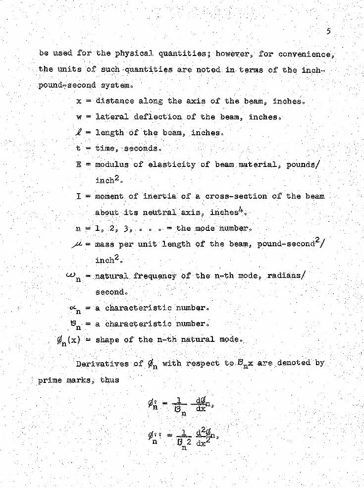
be used for the physical quantities| howevery for convenience the units of such - quantities are noted in- terns of the inch? pound?second -systemo , ; :
x = distance along the axis of the beam, incheso w = lateral deflection of the beari? inches»Jl - length of the beams, inehesv ■
' t = time., seconds = : - V V /3 - modulus of elasticity of beam materials pounds/- inch^s :I - moment of inertia of a cross-section of the beam .
, about:-its neutral 'axiss inches^? ■; - • -' ;;;:.n - 1, 2, 3S: « o o - the mode numbero
= mass per unit length of the beam, pound-second^/ inch^o
= natural frequency of the n-th mode» .radians// 'V" 'secondo." : ' ■ v -- - - ; : :'^ = a characteristic numbero
= a characteristic numbero■ n . • r ■. ^(x) = shape of the n-th natural modeo -
.Derivatives of 0n with respect to. Bmx are denoted by
prime marks$ thus
A
.0* * =
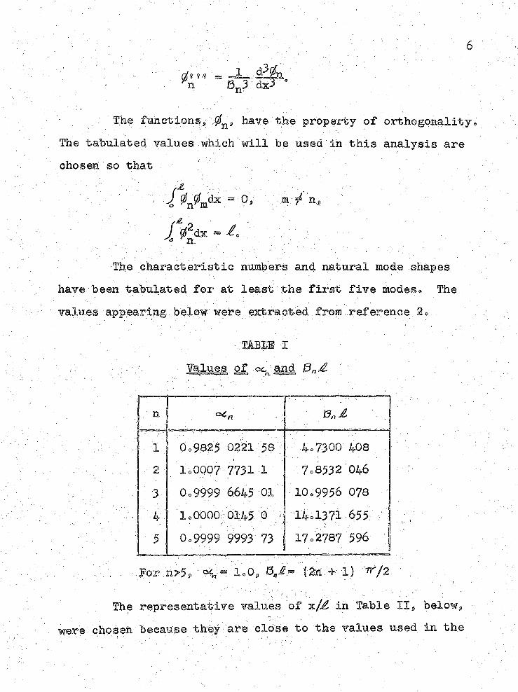
- ; : The fmnctionsp ,0nS have the property of orthogonalityThe tabulated values which will be used in this analysis are chosen so that " ..
n>
j m5 n.
The characteristic numbers and natural mode shapes have been tabulated for at least the first five modes# The values appearing bel^w were extracted,from,reference .
m s m I ': Values of oc and 6 n£
n
'1 : P c 9 8 2 5 0 2 2 1 5 $ ; 4 = 7 3 0 0 4 0 8
2 . l o O O O ? 7 7 3 1 1 7 o 8 5 3 2 0 4 6
3 O o 9 9 9 9 6645 01 . 1 0 s 9 9 5 6 0 7 8
l o O O Q O 0 1 4 5 0 0 - 1 4 o l 3 7 i 6 5 9 7
■ .5 0 . 9 9 9 9 9 9 9 3 7 3 1 7 = 2 7 8 7 5 9 6
t '1
. Por n>53 < = loOj, 8 ^ = (2n + l) ^/2 .
The representative values of x/^ in Table II, below.were chosen because they are close to the values used in the
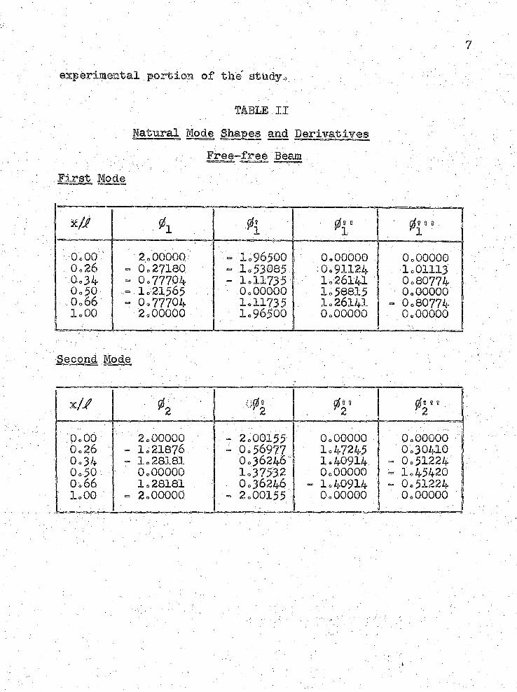
experimental.portion of the gtmdyo ■.'.
mBEE IIINatural Mode Shapes and Derivatives
Free-free Beam First Mode •
- ' ' 1■h
■ gfs 8----- -irm
■ 0*1* -;■
0,00 2.00000 - 1.96500 I 0.00000 0.000000.26 - 0.27180 - 1.53085 :0.91124 1.011130.3 4" - 0.77704 - 1.11735 1.26141 0.807740.30 --1.21565 0,00000 1.58815 0.00000, 0.66 - 0.77704 1.11735 1.26141 ■- 0.807741,00 2.00000 1.96500 0.00000 0.00000
Second Mode
x// 4 ;: | o0^ ^2
:o.oo ■ 2.00000 - 2.00155 0.00000 0.006000 .26 -1.21876 - 0.56977 • 1,47245 0.304100 .3 4 - 1.28181 0.36246 1.40914 - 0.512240 .5 0 0.00000 1.3753.2 0.00000 - 1.454200 .66 1.28181 0.36246 - 1.40914 - 0.512241 .0 0 -2.00000 - 2.00155 0.00000 0.00000. 1 ' - - '
8
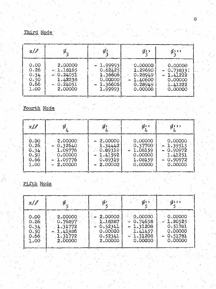
Third Mode
■ ■x// 4 4' 09 9 8
30,00 2,00000 - 1.99993 0=00000. 0=0.00000o26 1=18165 0=62425 1=29690 - 0=73833!0 ,3 4 . «= 0=24051: • 1=36606 0,28949 ' - 1=412220.50 1=42238 0=00000 - 1=40600 0=000000o66 . ■ - 0 = 24051 “ lo36606 0=28949 1=412221,00 2 = 00000. I.99993
b J -1 . -0=00000
----- -0,00000
Fourth Mod®
- J - ' 1 ■ • |x// X 4 4 '
d i n4
0=00 2,00000 4» 2 0 0.0000 0=00000 0=000000=26 ;' - 0=32640 . 1 =34442: 0=37700 1.395150=34 1=09776 : 0=89319 - 1=08159 ■ - 0 =.90972
. 0=50 0,00000 = 1=41592 0=00.000 1=412510=66 - 1=09776 0=89319 1=08159 - 0,90972.
. 1=00 - 2 = 000.00 2 = 00000 ' 0,00000 0,00000
Fifth Mode
x / y4
0.' ^5
- — . , , ;
09 8 8
/. 0=00 . 2=00000 2=00000 0=00000 0=00000! 0 = 26 .0=76897 : • I., 18287 - 0=74658 - - 1=20525
0 .3 4 . v : . . 1=31772 . . - 0.52341 - 1=31208 0=517810 = 50 - 1=41386 , 0=00000 1=41457 0=000000=66 1=31772 0 =5 2 3 4 1' - 1=31208 - 0=517811=00 2=00000
: - 1 11 - 1' ' -- - - -
2=00000~ — ...— ' —
0=00000 — — _ J
0=00000
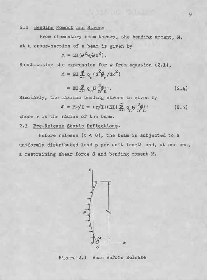
2.2 Bending Moment and StressFrom elementary beam theory, the bending moment, M,
at a cross-section of a beam is given by M = EI(<9^w/&x^).
Substituting the expression for w from equation (2.1),M - El £ q (d20 /dx2)
n=l n n
= EIS V n^A'* (2‘4)Similarly, the maximum bending stress is given by
«- = M r/I = (r/l)(EI)£ q 15 20 ‘* (2.5)/?=/ n n nwhere r is the radius of the beam.2.3 Pre-Release Static Deflections.
Before release (t < 0), the beam is subjected to a uniformly distributed load p per unit length and, at one end a restraining shear force S and bending moment M.
Figure 2.1 Beam Before Release
; ■ ■ 10
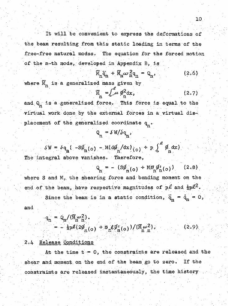
It will be eonvenient to express the deformations of the beam resulting from this static loading in terms of the free-free natural modeso The equation for the forced motion of the n-th modes developed in Appendix B, is
. ' : Bn V + = V (2.6)where M„ is a generalized mass given byn ^ f£
1 - / ^ ^ 2dxs (20 7)n ° nand % is a generalized force« This force is equal, to the
■ ■■■; : . .. ■: ■ virtual work done, by the external forces in a virtual displacement of the generalized coordinate q o1. ‘ n
® = SW/S q p• ■ -21-,.
- % ( -s%(c) - + p fThe integral above vanishes = Therefores
- (s0n(o, + Men (o)) (2.8);where S and M 9i the shearing force and bending moment on the end of the beam, have respective magnitudes of pj and |p£2». ; .
Since the beam is in a static condition, q = qn - 0S■ ■ - ■ nand . ; ; '
qn == - ip/Z(20n(o) + 0n£0*(o)}/(Mc.2), (2.9)
2o4 Release Conditions — -------— "At the time t = 0, the constraints are released and the
shear and moment, on the end of the beam go to zero = If the constraints are released instantaneously, the time history •
11
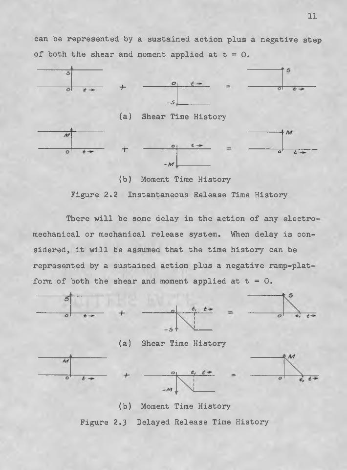
can be represented by a sustained action plus a negative step of both the shear and moment applied at t = 0.
+
-5
(a) Shear Time History
4-—M
o t
(b) Moment Time History Figure 2.2 Instantaneous Release Time History
There will be some delay in the action of any electro mechanical or mechanical release system. When delay is considered, it will be assumed that the time history can berepresented by a sustained action plus a negative ramp-plat form of both the shear and moment applied at t = 0.
(a) Shear Time History
(b) Moment Time History Figure 2.3 Delayed Release Time History
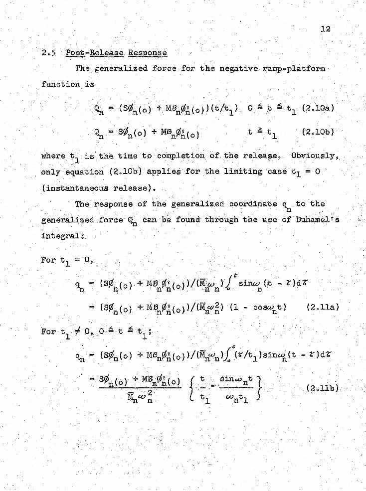
2 0.5 Fost-Belease Response ' ■The generalized foree for the negative ramp=*platfom
function is
Qq = (S|Zln(0) * 0 > t; S tl (2.10a)
- S0n (o) * M0nizl«(o) t = t- (2o10b)
where t- is the time to eoinpletion of the release» Obviouslys» only equation (B»10b) applies for the limiting ease tj = 0. (instantaneous release)e .
The;response of the generalized coordinate to the generalized force earn be found through the use of Buhamel8s integral:
For tj = 0# .
= (S0n(o) + MB 1 (o))/®n«'2) (1 - eoe^tl (2.11a)
For t f 0, 0 = t = tn ;1 1'
qn = <S0n (°) (2r/tl,sln‘nlt - r 1dZ
S4 (o) + W m%(o) f t -O'
Mn^n. *1 ‘untl(2.11b).
13
for ^ t-jj .:.'V
J4n< V f™t- rsin% (t ■L n 1+ eos<2> ft •=» t, ) 4»c6r f aina/ (t » ^)dT } n JL - a -c,; ' n _ . . . -
— S0n(o) » MBp0 (o) f l * sing(t - t ) - sina t 1 (2.1I0)
The response of the generalized coordinates is the sum of the responses to the sustained shear and moment and to the negative step or ramp^platform function of shear and moment s equations C2o8) and (2ol0)>
For t.
”
os'¥ n (o) + mbb 0* (o) C°S% t ) ,■ (2.12a)
Mn % 2
For t^ / 0 0 - t ^ t :
qn =# n 2 '
= 'ti; ■'
Ij
(2.12b)
For t^ y 0, t = t^;
, = s^n(°) ^ Mt3nfe(0) ["sin^n (t - t^) - sino^t (2.120)Mn % 2 1
It should be noted that the time dependent portion of equation . (2.12c) goes to - cos# t as t goes to ,zer©. This
14
agrees with equation .(2ol2a) aThe time dependent portion of equation (2®12c) can be
expressed in a more convenient form/
■/ sinol (t > tj)- a sim&^t: ~
wherev^sihC^t 4- ^n )> (2.13)
“ “ 1/2(1 - , 12.13a). and::: ; : v- / .v_ : ' : v
9/n = aretan(sina^tj./(1- - eos^t^)). (2.14b)A has been plotted for values of o^t/ up to 10 ir
(see Graph X? Appendix 0). • ' ’ , ■ . .
2.6 Magnification of StressesIn the pre-release eonditions the bending moment at a
point x along: the beam is given by. ' : -v
M_ ^ ip^2(l - (x/^))2. (2.15)For the dynamic responses the bending moment is given
by equation f 2.4) ® 'Substituting the values for q from equa- tions (2.12) gives
»d ” BI SlSn^n’tS^nlo) ■+ M ^ ( o ) )fn(t)/(Mn“n2) >where - .. ■' : : ■ . : ..: ■ : ..■■■■ .1 ,v, . . . ;' v ; ' ; a : - 8 ='p/s ' ■ . /
: M = |p^2s ' • :
. ; ■ r :' ’. %:(t) ; ' (ti". :oj
.15
; fn(t) |(l - 1 / * ^ } (tl V
fn(t ) " Ansl“: K % + .1 (*1 > 0, t « tl)W " /- . '
' -'<' v . ' K; : - :Rearraiiging and simplifying gives the following expression for M^g
o o
Hd = i p ^ S l
The ratio of :the dynamic bending moment to the static bending moment at a point x// is given by
(2.16)
Md = ■ 1 ^r :n==i { i s i ' S y k n(qcAf.n(t):° (2.17)
The maximum stresses in the outermost fibers of a beam are directly proportional to the bending moment, at the point»The stresses can be found by substituting the proper physical quantities into ' ' y ; - . . .
Therefore^, equation (2.17) applies equally well to the ratioof maximum dynamic to static stressess ^ ^ s°
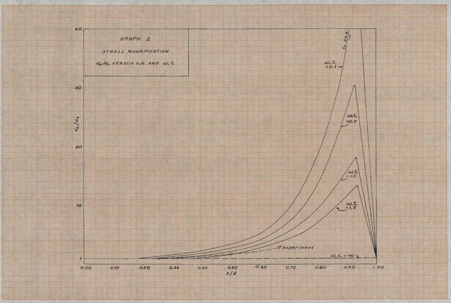
A plot of the ratio of maximum dynamic (summation of
i. . .appears in Graph 2 (Appendix 0). The minimum value of the
ratio is one.
.five modes) to maximum static stress versus .x/f and
2c.7 Bis'cusslbn of Theoretical AnalysisIn the expression for the dynamic bending moment
Mel -r
n=l v'^ ( o ) + <$i»r} d ’.’f ..
the terms in the series vary m t h n 0 The order of magnitude oT the quantities can be established!
X ( o ) » 4(0). t h ) - 1- ; "
en -n.
fn(t) 1” fcl = Oo
n(t) l/n2s tn > Oo
Thusp the order of magnitude of the terms of the series is:(Md)n ~ i/n, ; t£ * 0.
(Md)n ~l/n3. tj_ >' 0,
It may be concluded that the bending moments resulting from ah instantaneous release, t^.= 0, may become very large and may, in fact, be unboundedo For the case of a delayed release, the bending moments can be expected to be smaller and are bounded» /in examination of the results shown in ' Graph 2 bears this out e It can be seen that the stress magnification can become large, particularly near the initially free end of the beam>. Further, it Is evident that a delayed release reduces the stress magnification, A consideration of damping would serve to reduce the response further.
3 ® GONDUGT OF S3®ERI3yiENT
3°1 Release Mechanism :' It was necessary to select or devise a ■release mech
anism that would§ay Restrain a beam in a cantilevered position® b_0 Be capable of a sudden release (small value of
■ y)' ■ . ■ v, Oo ■ lot impart motion* translatory, rotational or
vibrational^ to the beamo ■do Provide uniform action through several trialso It was desirable that the constraints be in the form
of pure moment and shear« However9 if the release time were such that the higher modes would not be excited measurablyj, a pair of force constraints close together would duplicate a moment and shear constraint satisfactorilyo
The release mechanism chosen utilized two solenoids parallel wired to a standard 110 volts 60 cycle source* The solenoids are those used in the Maytag washing machine®These particular solenoids were chosen because they have a square piston action and they are sturdy enough to maintain the beam in a cantilevered positidn6
in aluminum biochi 3 x l x 0o750 inches$ was drilled
17
18
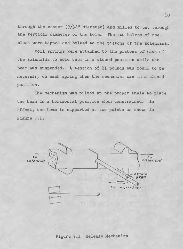
through the center (9/32” diameter) and milled to cut through the vertical diameter of the hole. The two halves of theblock were tapped and bolted to the pistons of the solenoids.
Coil springs were attached to the pistons of each of the solenoids to hold them in a closed position while the beam was suspended. A tension of Ij pounds was found to be necessary on each spring when the mechanism was in a closed position.
The mechanism was tilted at the proper angle to place the beam in a horizontal position when constrained. In effect, the beam is supported at two points as shown in Figure 3.1.
to■&o/e.no/c/
to a m yC? / / /
Figure 3.1 Release Mechanism
: ■ ■■ ■ 1 9 .
3 p2 Beam Selection : •., A. four-foot length of I.-in eh diameter aluminum rod m sehoseno The weight of the rod Was small enough to permit the use of the release,mechanism selected and the flexural rigidity was low enough to provide easily measurable strains, ■ 1 The circular eross-seetion was favorable for a sudden release since any lateral motion of the mechanism tends to move the constraining elements away from,the beam,
; ■ The dimensions, and weight of the rod were measuredcarefully. The values are shown in Appendix A,. Symbols and Units;, The modulus of -elasticity was; found froia the fundamental frequency of the rod in the cantilevered position,
3,3 Stress MeasurementSH-4 strain gages were affixed, to the rod at five
points. The x/6 ratios of these points a r e -
a, • 0,0254° ,bo Go2482, . '
: o-i 0,3365.: : ' :."f v' d, 0,5016.
e,, 0o6674oPoint a was useful only as an indicatpr of release time! the effects of flexural vibration are negligible this close to the end of the rod. The remaining four points$, h, through e^ are referred to as points 1 through 4 respectively. •
20
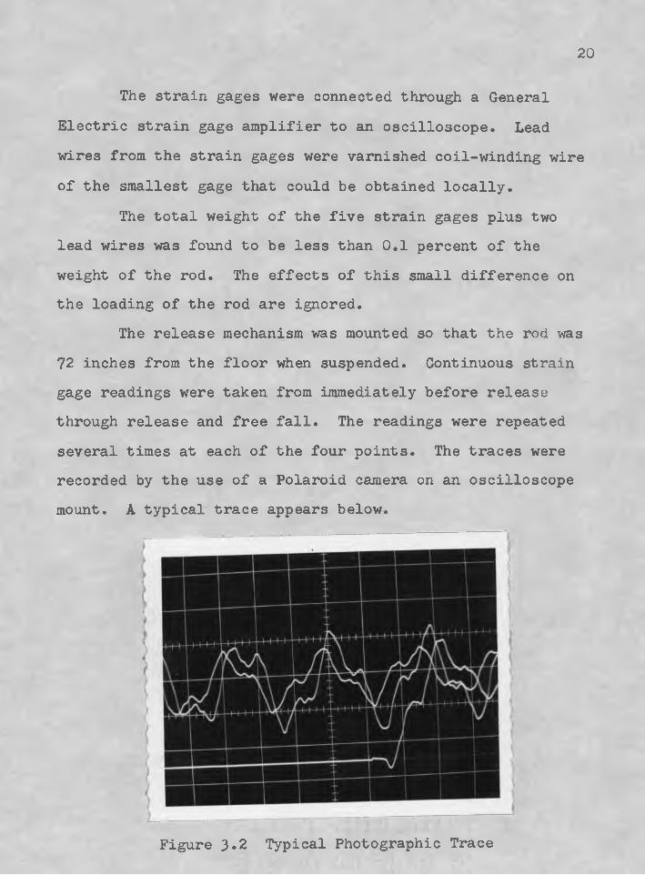
The strain gages were connected through a General Electric strain gage amplifier to an oscilloscope. Lead wires from the strain gages were varnished coil-winding wire of the smallest gage that could be obtained locally.
The total weight of the five strain gages plus two lead wires was found to be less than 0.1 percent of the weight of the rod. The effects of this small difference on the loading of the rod are ignored.
The release mechanism was mounted so that the rod was 72 inches from the floor when suspended. Continuous strain gage readings were taken from immediately before release through release and free fall. The readings were repeated several times at each of the four points. The traces were recorded by the use of a Polaroid camera on an oscilloscope mount. A typical trace appears below.
Figure 3.2 Typical Photographic Trace
22
There is a distortion of two percent over the width of the photograph due to camera, astigmatism,, Additionally^ the camera does not record the full width of the grid.There is a time blank of 0®.G25 seconds from the right edge to the, left edge of the photograph (b earn travel is from \ left to right)o . .
‘ The solenoid pistons do not begin to move immediately with the closing of the switch® There is a reaction to the initial power surge that is evident in the first minor changes in the trace of the oscillosoope beam® Time zero has been taken as the beginning of the first major change in. position rather than the initial reaction to the power ■surge®, . . 1 ' . ■ '
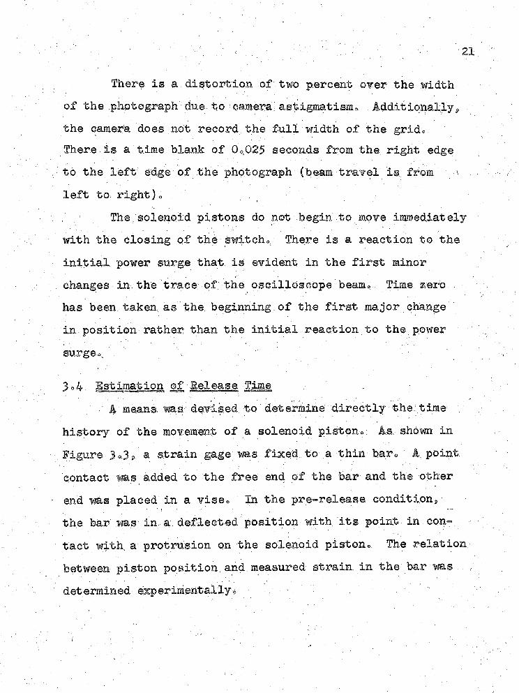
;3»4- Estimation of Release Time:: . ‘ A means, was- devised, to ' determine directly the time
history of the movement of a solenoid piston® As. shown in : Figure 3 ®.3 g a strain gage was fixed to a thin bar® A point contact was added to the free end of the bar and the other end was placed in a vise® In the pre-release conditions the bar was- in a deflected position with its point in contact with, a protrusion on the solenoid piston. The relation between piston position and.measured strain in the bar was , determined experimentally® .
22
f>— strain page
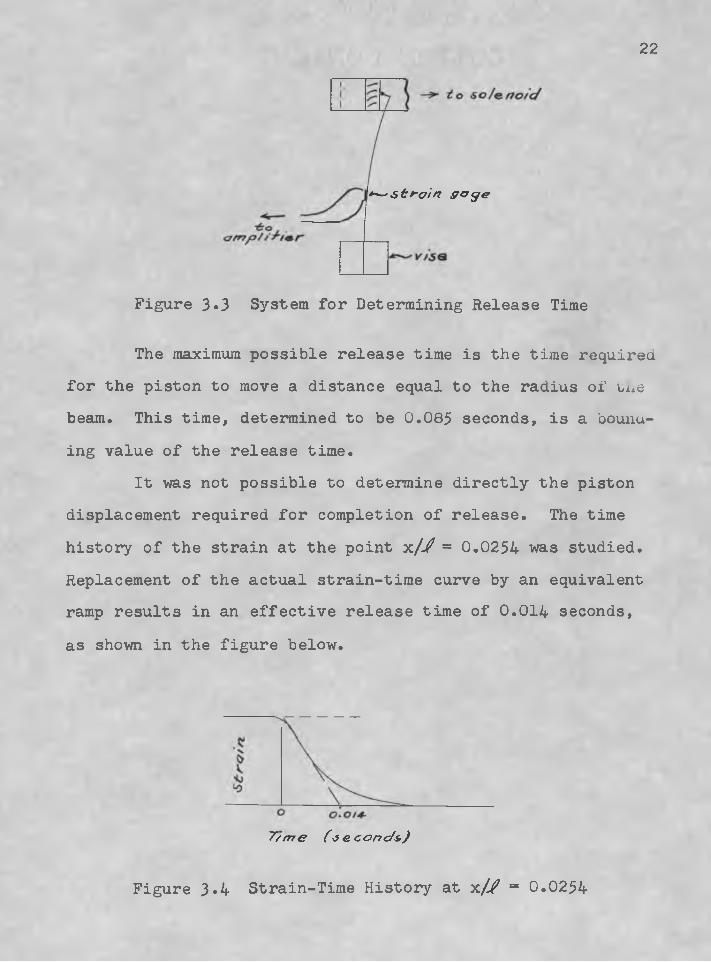
Figure 3*3 System for Determining Release Time
The maximum possible release time is the time required for the piston to move a distance equal to the radius of tne beam. This time, determined to be 0.085 seconds, is a bounding value of the release time.
It was not possible to determine directly the piston displacement required for completion of release. The time history of the strain at the point x// = 0.0254 was studied. Replacement of the actual strain-time curve by an equivalent ramp results in an effective release time of 0.014 seconds, as shown in the figure below.
7/m e (je.conc/&)
Figure 3*4 Strain-Time History at yl/j? = 0.0254
4o COMPARISON OF THEORETICAL AND EXPERMMTAL RESULTS
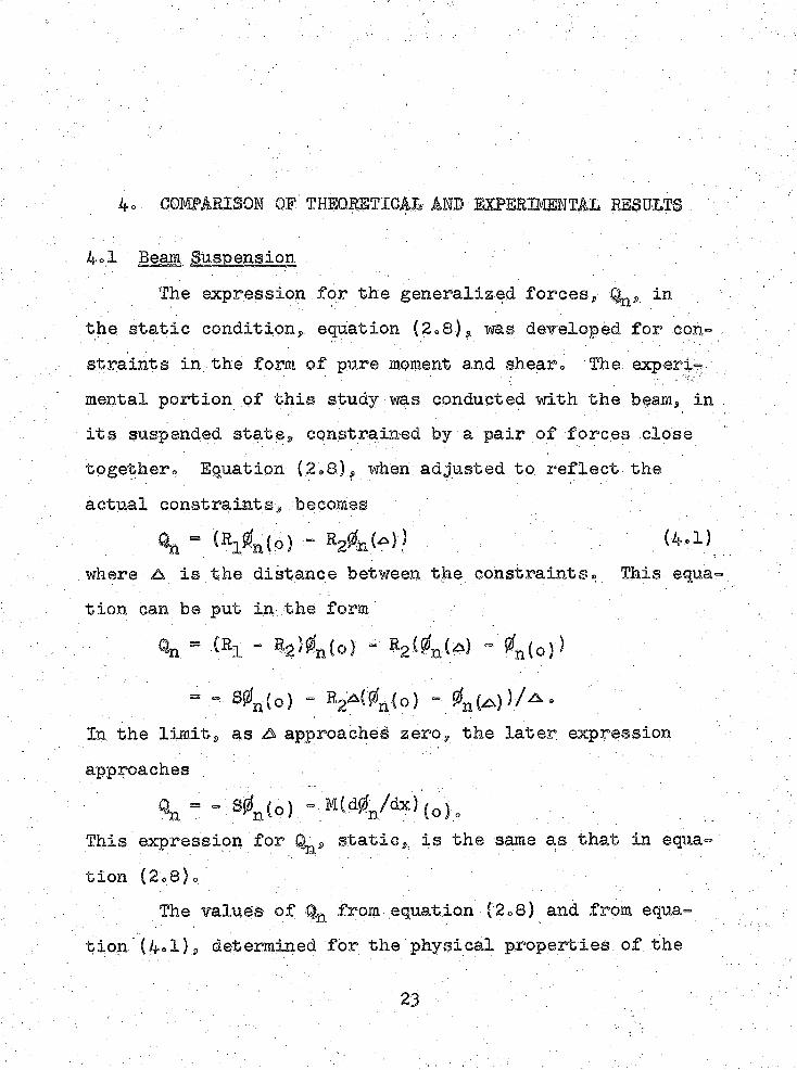
4*1 Beam SuspensionThe expression for the generalized, forces? in
the static condition,, equation (2 = 8), -was developed for constraints in the form of pure moment and shear® The experil
■ .■ . • ■ ■ ■ . . ' ' ' .y ' / - . r’V.;; ' :
mental portion qf this study was conducted with the beam, in its suspended state, constrained by a pair of forces close together. Equation (.2»8)? when adjusted to reflect the actual constraints, becomes .
Al = tBAts) - E2&<1 > . (4-.1)where A is the distance between the constraints® This- equation can be put in the form' ::
On = { % - % ) 4 ( o ) - R2(4 ( l “ ^(o)*
= - S0n.(o) - Bga(0g(o) - 0n ( ,))/•*••In the limits as A approached zero, the later expression approaches
^ “ l s0n(o) -This expression for S-s static, is the same as that in ©qua-
tion (2o8)*The values of Qn from equation (2o8) and from equa
tion (4*1), determined for the physical properties of the
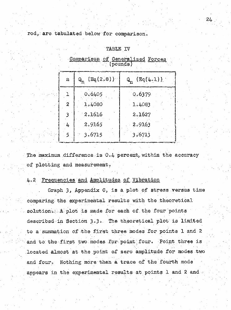
rods- are tabulated below for comparison.,.
'TABES I?Comparison .-of Generalized Forces
(pounds)
h % (Bt(2e8)) % (EqC4.1))/
■;;i : 0>6405 0,6379 .'2 1.4080 1=40833 2»16X6 2=16274 2e$165 2=9163
- ■ 5 ■ 3.6715 : v: 3.6713 ; ;
The maximum difference is 0,4 percents within the accuracy of plotting and measurement? -
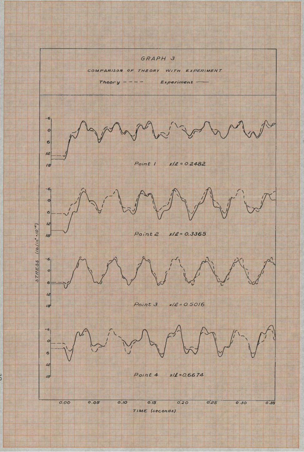
4o2 Frequencies and Amplitudes of Vibration. Graph 3 s Appendix G* is a plot of stress versus time
comparing the experimental results with the theoretical solutionw A plot is made for each of.the four points described in Section 3°3o. The theoretical plot is limited to a summation of the first three modes for points 1 and 2 and to the first two modes.for point ; four® 'Point three is ■. located almost at the point of zero amplitude for modes two and four* Nothing more than a trace of the fourth mode appears in the experimental results at points 1 and 2 and
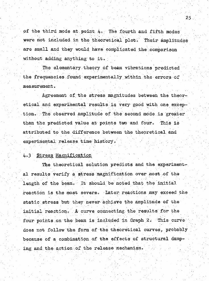
Of the third mode at/peint ,4o: The fourth and fifth modes were hot inoluded in the theoretical plot® Their amplitudes are small and they would hare complicated the comparison without adding anything to it*
The elementary theory of beam ribrations predicted the frequencies found experimentally within the•errors of measurement e ,
Agreement of the stress magnitudes between the theory etical and experimental results is rery good with one except tione The observed amplitude of the second mode.is greater than the predicted value at points two and four® This is attributed to the difference between the theoretical andexperimental: releas® t-hM history«, : - .' >, ,: ■ ;
4o3 Stress Magnification " "The theoretical solution predicts and the experiments
al results verify a stress magnification over most of the length of the beam0 It should, be: noted that the Initial reaction is the most severe«. Eater reactions may exceed the static stress but they never- achieve the amplitude of the initial reaction® A curve connecting, the results; for the four points on the beam is included in Graph 2® This curve does not follow the form of the theoretical curves, probably because of a combination.of the effects of structural damping and the action of the release mechanism®
CONGHJSIONS
Elementary bearn theory predicts that the bending stresses resulting from the sudden release of a uniformly .loaded cantilever beam may exceed the bending stresses., due to the static' loadings For'an instantaneous release, the magnification will be large and, if damping is not considered, is unboundede .For a delayed release, the magnification is reduced below that in the Instantaneous ease®Thus, a delayed release would be'desirable if it were necessary to limit the stresseso
The experimental results reinforce this conclusion® The experimental results were in good agreement with those predicted by the theoryo
26
Appendix A
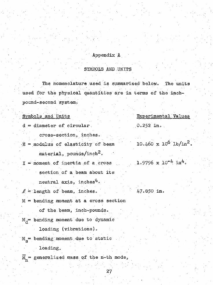
Simms AND UNITS, The nomenclature used is summarized belowo The units
used for the physical quantities are in terms of the inch™ pound-second system^
Symbols and Units N Experimental Valuesd - diameter of circuiar 0.252. in® .
oross-seetions.„ inches® .S = modulus of elasticity of beam 10o460 x 10^ Ib/in^®
materials pounds/inch^oI - moment, ©f Inertia of a .cross . .. . 1 = 9796 x 10“^ ih^®
section of a beam about its neutral axiss, inches^o .
J? ~ length of beam9 inches. . 47®850 in.M.= bending moment at a cross section
of the beam^ inch-pounds.Md= bending moment due to dynamic
loading (vibrations). .bending moment due to static . ' . ■
S ' ' " " ' ' ; ' ' . ■' . ; . ’■ ■ ■ . ■ : . - • .
loading. . ’ ■ ' ■ - ' .;M = generalized mass of the n-th modeg
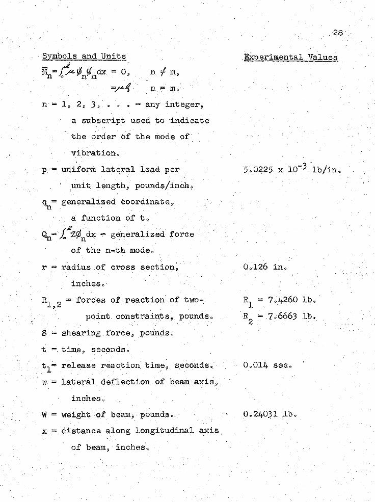
Symbols and Units= .0, n $ m 9
’ n f So- -n = 1, 2,. 3 s> ® o. » = any integer9
a subscript used to indicate the order of the mode of vibration.
p = uniform lateral load per . ' unit lengthp pounds/inch.
q^- generalized coordinate9 a function of t.
Qn- 20ndx ? generalized force of the n-.th mode,
r = radius of cross section,' inches.
R- 0 = forces of reaction of two-■ls2 " ; , .. :
point constraints, pounds.S = shearing force, pounds. t =. time, seconds«, tv® release reaction time, seconds® w = lateral deflection of beam axis,
inches®* = weight of beam, pounds, x = distance along longitudinal axis
of beam, inches® ;
,, 28
Experimental Values
5.0225 x lO^ lb/in®
■ ' ' ' 1 , ,•
0.126 in.
R- = 7.4260 lb® l ;•R2 = 7.6663 lb.
0.014 see.. /
0.24031 db.
29
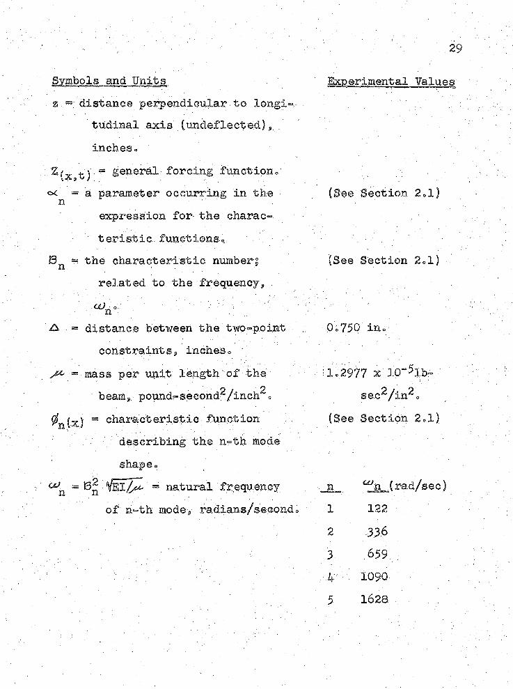
Symbols and Units% distanoe ^erpendioular. to longi=-.
tudinal axis (undeflected.) $ . inches®
Experimental Values
Z(x$t j = general forcing functionso< = a parameter occurring in the n ;
expression for the eharae-(See Section 2ol)
' teristic.functions*;=r the characteristic number;n- ‘1 . ■" . ■■ . .
(See Section 2*1)related to the frequency^a/,® ' \ v'-: \ ' ' n V; ■ ■ -
A = distance between the two=-point constraihtSp inches® v
0,750 in®-
-■ mass per unit length"of the - beams pound™second^/inch^ e
:1®2977 x 10-5lb-se.e^/in^o
0n (x} ~ characteristic function; describing the n«=th mode
(Bee Section 2«1)
shape®o0n ^ = natural frequency
of n-th mod6$, radians/secondo■ n. 00n (rad/sec)1 122 ' •
2 3363 .659 .r 10905 1628;
Appendix B
DEVELOPMENT OF THE EQUATIONS OF LATERAL VIBRATION
B.l Free Vibrations of Beams.The development that appears below is essentially the
same as that in reference 1, pages 331-333•
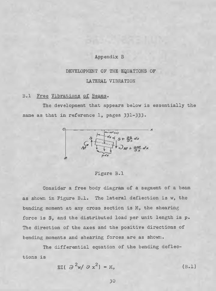
Figure B.l
Consider a free body diagram of a segment of a beam as shown in Figure B.l. The lateral deflection is w, the bending moment at any cross section is M, the shearing force is S, and the distributed load per unit length is p. The direction of the axes and the positive directions of bending moments and shearing forces are as shown.
The differential equation of the bending deflec
tions isEI( 92w/ 5> x2) = M, (B.l)
30
where E is the modulus of elasticity,. I is the cross-*" sectional moment of inertia and the product 11 is the flexural rigidityo •
A consideration of the equilibrium of the beam segmentleads to : , ; . ' ■ \ ' - '
(a/sx) ) = 5>My4>x - - g [Bo2)V ('Sp/siz '} (Ela^wy^x2) = = <9S/o?x — p (B»3 )
Applying l $Alembert8s principle, the inertia force per unit length is given by
p = '' ■where/^is the mass of the beam per unit lengths
Substituting equation fB<,4) for p into equation (Bo3) s, the general equation for the free vibration of the beam becomes
(<92y^x2) i(El>>?wyfe>x ) = > ^ d 2w/9t2o (Bo5)This is the well-known Bernoulli-Euler equation0
In the particular case of a uniform beam, SI is constant along the length of the beam and equation |B0 5) becomes
ElArykxk 4 te>2w/<9t2- Q,
' or ■ '■; ' . :■ ’ / - \ ■ • . / /- " :-t a^t^w/at^) = 0, fBo6)
in which ■ ,a2 =^/(El)
32
B.o2 Normal Modes of. Vibration -When a beam performs a normal mode of vibration, the
defleetion at. any location varies harmonically with time andcan be represented as follows §
w = 0(4eGs<ut 4- Bslntot). - (Bo?)where 0 is a function of the coordinate x and represents the shape of the normal mode under consideration j u> is the natural frequency eorresponding to the particular mode shape® Substituting equation, ('Bo?) into -equation |Bo6) $ we obtain,..
= Oo (BoS)By using the notation
’, ; . . a2 ==z 2/(EI),; = k4y • ■ (B+9),it can. be shown that sin kx, cos kx, sink, kx and cosh kx will be solutions of equation CBo8) o. The general solutionof this equatioh. will be ;; ' : ' ; f0 ~ S^sin kx + GgCos kx 4- G^sinh kx 4* G^cosh kx, (Bo 10)
in which 0^, Cg, 0^ and are constants to be determined in a particular case from the conditions at the ends of thebeamo Applications of the four end or boundary conditionspermit the determination of the relative magnitudes of the arbitrary constants of the .general solution (Bo.10). and the frequency equation in k hr The modes of natural- vibra- /■,. -; tion and their frequencies will then be established^ By superimposing all possible normal vibrations, the general
expression for free.lateral vibrations becomes
w = -^-^n^n008^ * (Bell)
Bo3. Forced VibrationsIt is convenient to express the forced motion of a
beam as a superposition of the motion in the normal modes 0^2 each having an amplitude gni;referred to as a generalized coordinate =
: ■ C O . : >
' ’ w ” f' : : (Bo 12)' n=l ' . ; ■ ■ .where 0^ Is a function of x and qn is a' function of to ■
The differential equation for forced vibrations is (d^/sx^) (Sl^w/^x^) = Zg (Be 13)
, where ,'S: is a ' function ;Qf.x and, t Substituting the value .for w from equation (Bo12) into this expression, we obtain
: a y E^ ' ) - * v # „ % > z , ( B a awhere the primes indicate derivatives with respect to x and the dots indicate derivatives with respect to te
From the homogeneous portion of equation (B014), by • separation of variables,.; we get . . , :
' . T 0, ' . ' . . ; ■( $ # « ) " -^«?n0n = 0.
Making use of the later identityi- equation (B.14) can be written in the form . . ' .
Multiplying both sides by 0m and. integrating" with respect to
x from zero, to/givesrJ£
x (B»15)The functions representing the normal moies of vibra
tion are orthogonal= The values of $ as tabulated in various references are chosen to give9. for a uniform beams
/ = 0 n /■ m
n = m s
All values.of the summation reduce to zero when n is not equal to m0 For n equal to m,. Equation. (Bol5) becomes
“ 'm’l m / ^ 4 d x + qm />« d x = / z 0 mdxor ' : . ■' ■ ; . ' : " ■■ ' • ■ '
= ' (Bel6)where
, ' ' ‘ '• ■' ■■■ _ . ■ >■ : ■ . ' ' .: Mm. ”^ S£'0radx ~ generalized mass?
g^bdx = generalised force*
Bo4 Assumptions and Their Effects -The expressions for bending moments and stresses
resulting from flexural vibration developed in the preceding sections are,based on the usual assumptions of elementary beam theoryo. These assumptions have proven valid for most engineering applications* They arer
a® The deflections are small®bo The effect of shearing force is negligible®
. Co The effect of rotary inertia is negligible? 'One of. the two implications of small deflections, is
that the slopes are smallo The bending moment at a cross section bn the beam is then proportional to the radius of curtature at that point»
The second implication of small deflections is that the stresses are below, the elastic limit and that no plastic deformation occursrthe material obeys Hookers law® If the stresses exceed the elastic limits the energy losses will be
high and the predicted mode shapes and frequencies will not be valid® ' „
'Gorrections.for shearing.force and rotary inertia of elements of the beam become important in studying the modes of higher frequencies® At the higher frequencies the beam is divided by nodal cross sections into comparatively short.portions® . . •
The assumptions listed above are well within the accuracies of.this study and mo corrections have been made for plastic deformation^ shearing forces $ or .rotary inertia®

Appendix 0
m m m m rspeesentations
36;
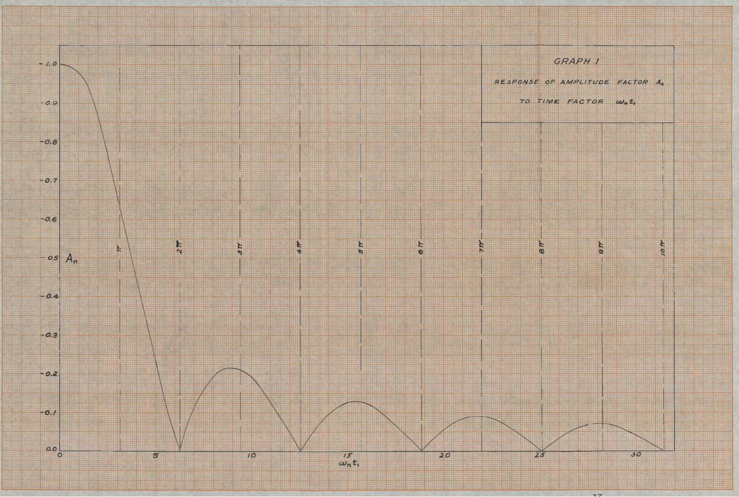
GRAPH /
R E S P O N S E O F A M P L I T U D E F A C T O R A,
T O t i m e f a c t o r- 0.9
- 0.5
-r
<r/d
S T R E S S M A G N I F I C A T I O N
tXdte* S/ERSUS X/£. A N D OJ, T,
= /.O
experiment
Uf,t, = oo-t0.90 /.OOO.SO0.700.40
6TVt'f'xStS
(lb/in’ */0"
G R A P H 3
C O M P A R I S O N O F T H E O R Y W I T H E X P E R I M E N T
x M $ O.2 4 & ZPoint /
P o / a t <2
Point \3 x/jZ* 0.50/6
x/jZ-O.66 74-Point 4-
o.oo 0.20 0.30
T I M E (second*)
References
1. Timoshenko, n Vibration Problems in Engineering:,-Bo Fan No strand Goe s 1937» Second Edit ion $ Sections
. 54-58e - ; . ■ : ' - ■ , :• .2o Youngs Be, and Pelgar* ■.R». Tables of Characteristic
• Functions Representing Normal Modes of Fibration of Beams, University of Texass Engineering'Research Series Number 44» 1949« ' v
3o Leonards, Robert ¥= j, 0n Solutions for the TransientResponse of Beams, NASA Technical Report R - 2 1 1959 =
A. ; ..
m